

Page 1

ACCES I/O PRODUCTS INC
10623 Roselle Street, San Diego, CA 92121
TEL (858)550-9559 FAX (858)550-7322
Wireless Serial Modem
WM-01
USER MANUAL
FILE: MWireless Serial Modem.wpd
Page 2

Notice
The information in this document is provided for reference only. ACCES does not assume any
liability arising out of the application or use of the information or products described herein. This
document may contain or reference information and products protected by copyrights or patents
and does not convey any license under the patent rights of ACCES, nor the rights of others.
IBM PC, PC/XT, and PC/AT are registered trademarks of the International Business Machines
Corporation.
Printed in USA. Copyright 2004 by ACCES I/O Products Inc, 10623 Roselle Street, San Diego, CA
92121. All rights reserved.
WARNING!!
ALWAYS CONNECT AND DISCONNECT YOUR FIELD CABLING WITH
THE COMPUTER POWER OFF. ALWAYS TURN COMPUTER POWER
OFF BEFORE INSTALLING A CARD. CONNECTING AND
DISCONNECTING CABLES, OR INSTALLING CARDS INTO A SYSTEM
WITH THE COMPUTER OR FIELD POWER ON MAY CAUSE DAMAGE
TO THE I/O CARD AND WILL VOID ALL WARRANTIES, IMPLIED OR
EXPRESSED.
Page ii
Page 3

Warranty
Prior to shipment, ACCES equipment is thoroughly inspected and tested to applicable
specifications. However, should equipment failure occur, ACCES assures its customers that
prompt service and support will be available. All equipment originally manufactured by ACCES
which is found to be defective will be repaired or replaced subject to the following considerations.
Terms and Conditions
If a unit is suspected of failure, contact ACCES' Customer Service department. Be prepared to give
the unit model number, serial number, and a description of the failure symptom(s). We may
suggest some simple tests to confirm the failure. We will assign a Return Material Authorization
(RMA) number which must appear on the outer label of the return package. All units/components
should be properly packed for handling and returned with freight prepaid to the ACCES designated
Service Center, and will be returned to the customer's/user's site freight prepaid and invoiced.
Coverage
First Three Years: Returned unit/part will be repaired and/or replaced at ACCES option with no
charge for labor or parts not excluded by warranty. Warranty commences with equipment
shipment.
Following Years: Throughout your equipment's lifetime, ACCES stands ready to provide on-site
or in-plant service at reasonable rates similar to those of other manufacturers in the industry.
Equipment Not Manufactured by ACCES
Equipment provided but not manufactured by ACCES is warranted and will be repaired according
to the terms and conditions of the respective equipment manufacturer's warranty.
General
Under this Warranty, liability of ACCES is limited to replacing, repairing or issuing credit (at ACCES
discretion) for any products which are proved to be defective during the warranty period. In no
case is ACCES liable for consequential or special damage arriving from use or misuse of our
product. The customer is responsible for all charges caused by modifications or additions to
ACCES equipment not approved in writing by ACCES or, if in ACCES opinion the equipment has
been subjected to abnormal use. "Abnormal use" for purposes of this warranty is defined as any
use to which the equipment is exposed other than that use specified or intended as evidenced by
purchase or sales representation. Other than the above, no other warranty, expressed or implied,
shall apply to any and all such equipment furnished or sold by ACCES.
Page iii
Page 4

Table of Contents
Chapter 1: Introduction ..............................................1-1
Input Power ......................................................... 1-1
Serial Connections ...................................................... 1-1
Termination & Bias ...................................................... 1-1
Specifications .......................................................... 1-2
Chapter 2: Installation ...............................................1-4
List of Figures
Figure 1-1 Wireless Serial Modem Block Diagram ............................Page 1-3
List of Tables
Table 1-1: Base Station Specs ............................................Page 1-2
Table 1-2: 900 MHz Radio Specification ....................................Page 1-2
Table 1-3: 2.4 GHz Radio Specification .....................................Page 1-2
.....................................................................Page 1-2
Page iv
Page 5

Chapter 1: Introduction
The Wireless Serial Modems are capable of providing seamless dependable serial communications via
radio transmission. This unit can be used together with other Wireless Serial Modems or paired up with
our distributed I/O REMOTE ACCES products with a radio modem integrated in to it.
These units consists of two boards, a radio modem and a serial interface board. The interface board can
be either RS232, or RS485/422 compatible. The radio is a frequency hopping module that uses a standard
asynchronous serial data stream.
Input Power
The unit requires a externally supplied power and has two options to select from (regulated +5VDC or
unregulated +12VDC). Three terminals labeled +5V, GND, and +12V are provided.
5 Volts DC Regulated
The +5V is not regulated and is fed directly to the VCC circuit. Therefore if +5VDC is supplied to
power the module it must be from a regulated source.
12 Volts DC Unregulated
The +12VDC input has a range of +7V to +18V with an on-board 5V regulator in series with the
line. A optional DC to DC converter is available for lower power consumption when battery
savings or heat dissipation considerations are important.
Warning: The Wireless Modem requires that you supply only +5VDC or +12VDC, but never both.
Serial Connections
RS-232:
If wired “one to one” the DB-9 cable connection follows the standard for RS-232, 9 pin
connections. The connection should be wired as shown in Table 1. A female DB-9 cable should
mate directly to any standard RS-232 host mating connector.
RS-422 full duplex:
The HOST serial connection signal pinouts may vary from one manufacturer to another. The Host
Serial signals should be wired as above in Table 1. RS-422 protocol is provided on the board via
jumper selection (install a jumper in the RS422 position on the 485/422 jumper selection).
RS-485 (two wire) half duplex:
The HOST serial connection signal pinouts may vary from one manufacturer to another. The Host
Serial signals should be wired as above in Table 1. The HOST serial transmit and receive signals
are connected together via jumpers on the board (install jumpers on the RS-485+, RS-485-, and in
the RS485 position on the 485/422 jumper selection).
Termination & Bias
In order to avoid noise and reflections in long lines, a cable with a characteristic impedance of 120S
should be selected and the line should be terminated on both ends with 120S resistors. Termination is
provided on the board via jumper selection (TERM). For short lines (when the propagation of the signal is
less than 4% of the time to transmit a bit), the termination might not be needed
Manual MWireless Serial Modem.wpd
Page 1-1
Page 6
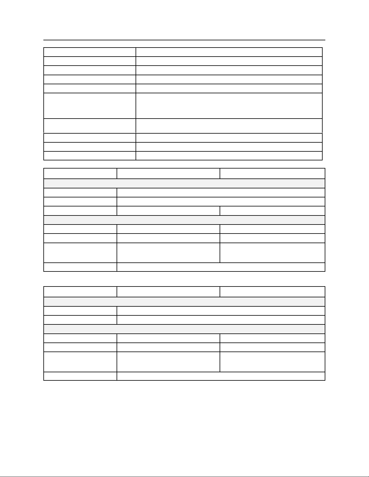
Specifications
External Regulated Power:
Alternate Unregulated Power:
Connections:
Baud Rate serial port to the modem:
Baud Rate over the air:
Serial Data Format:
Radio Data Buffers
Operating Temperature Range
Storage Temperature Range
Humidity
900MHz model
General
Frequency range
Type
Throughput
Performance
Transmit output power
Rx Sensitivity
Range
Interference Rejection
902 to 928 MHz, Unlicensed ISM Band
Frequency Hopping Spread Spectrum Transceiver
9600 bps 19200 bps
100mW 100mW
-110dBm -107dBm
Indoor: 600' to 1500'
Outdoor: 7 mi. with dipole,
over 20 mi with a high gain antenna
70dB at Pager and Cellular Phone Frequencies
+5 VDC +/-5%
+7 VDC to +18V
All connections made by removable screw terminal block
1200 to 57.6K Baud between wireless module and serial port
Factory selectable 9600 or 19.2K Baud transmission data rates
8 Character, No Parity, 1 Stop Bit
7 Character, Even Parity, 1 Stop Bit
7 Character, Odd Parity, 1 Stop Bit
7 Character, No Parity, 2 Stop Bits
132 Byte Data Input
132 Byte Data Output
-45 to +85 C
-50 to +120 C
5% to 95% Non-condensing
Table 1-1: Base Station Specs
9600 bps throughput 19200 bps throughput
Indoor: 425' to 1060'
Outdoor: 5 mi. with dipole,
over 14 mi with a high gain antenna
Table 1-2: 900 MHz Radio Specification
2.4GHz model
General
Frequency range
Type
Performance
Transmit output power
Rx Sensitivity
Range
Interference Rejection
Page 1-2
9600 bps throughput 19200 bps throughput
2.40 to 2.4835 GHz, Unlicensed ISM Band
Frequency Hopping Spread Spectrum Transceiver
50mW 50mW
-104dBm -101dBm
Indoor: 150' to 375'
Outdoor: 1.4 mi. with dipole,
over 12 mi with a high gain antenna
70dB at Pager and Cellular Phone Frequencies
Indoor: 106' to 265'
Outdoor: 1 mi. with dipole,
over 8.5 mi with a high gain antenna
Table 1-3: 2.4 GHz Radio Specification
Page 7
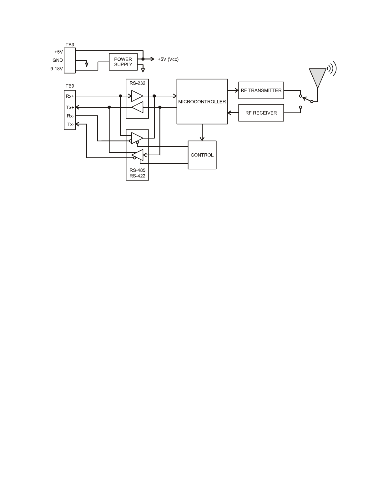
Figure 1-1 Wireless Serial Modem Block Diagram
Manual MWireless Serial Modem.wpd
Page 1-3
Page 8

Chapter 2: Installation
1. Configure the interface board jumpers
a. RS-232 requires no jumper settings
b. See Option Selection Section for RS-422 and RS-485 settings
2. Wire the serial port connection according to the connection table
3. Wire power connection according to the connection table
a. When using a regulated +5VDC
i. Connect +5VDC to TB4-3
ii.Connect ground to TB4-2
b. When using a Unregulated +12VDC
i. Connect +5VDC to TB4-3
ii.Connect ground to TB4-2
4. Check that your serial port settings are one of the following data configurations.
a. Baud Rate:
i.Default is 9600 baud for the 9600 baud module
ii. Default is 19.2K baud for the 19.2K baud module
b. Serial Data Format: 8 Character, No Parity, 1 Stop Bit
7 Character, Even Parity, 1 Stop Bit
7 Character, Odd Parity, 1 Stop Bit
7 Character, No Parity, 2 Stop Bits
Optional steps: To check operation of the wireless serial modem follow steps 3-5.
5. Locate and run ACCES’ WINRISC.EXE application program (easy-to-use serial communication
terminal program)
a. CD-ROM provided at :\disks\Tools.win\WIN32\.
6. WINRISC settings should be as follows:
Port: Set to the serial port that the Wireless Modem is connected to (COM1, COM2, etc.).
Baud: 9600
Parity: Even
Data Bits: 7
Stop Bits:1
7. Click the “Connect” button to connect the application to the Wireless Modem
8. Click the cursor into the large “data” area of the WINRISC screen.
9. If talking to a REMOTE ACCES Pod with a integrated wireless module send the ? command to
receive a response from your pod by typing ? and entering a carriage return.
10. If talking to another Wireless Modem, set that modem up following these steps on another system
or second serial port on the same system, and type anything at the keyboard to see the data
appear on the other system.
Page 1-4
Page 9

RS-232 Cable RS-422 Cable RS-485 Cable
HOST
RS-232
Signals
DCD
RXD
TXD
DTR
GND
DSR
RTS
CTS
RI+
TB-9
1
2
3
4
5
6
7
8
9
HOST
RS-422
Signals
Rec-(RX-)
Trans+(TX+)
Trans+(TX-)
GND
Rec+(RX+)
TB-9
3
2
7
5
6
HOST
RS-485 Signals
Trans+(TX+)
Trans+(TX-)
GND
TB-9
2
3
5
Manual MWireless Serial Modem.wpd
Page 1-5
Page 10

 Loading...