

Page 1
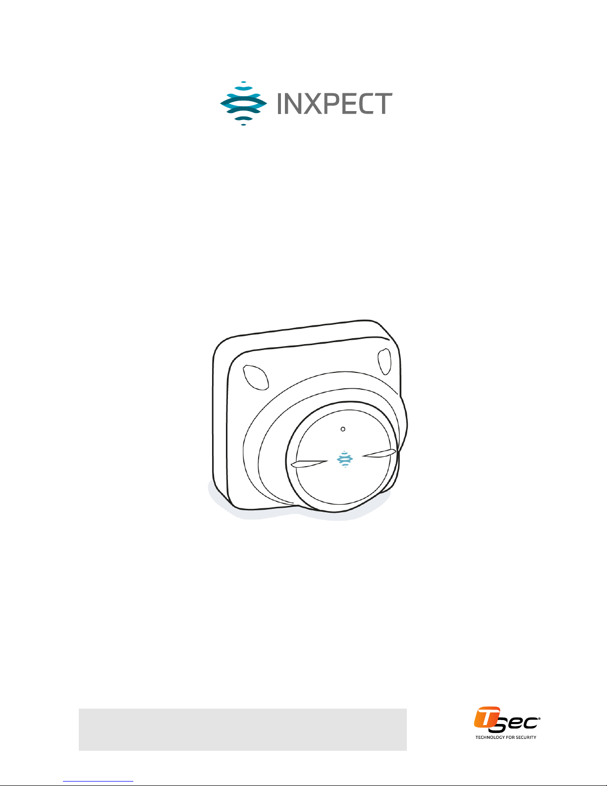
MSK-101
Carefully read this manual in its entirety.
You will find useful information to take full advantage of the product's potential, use it
safely and obtain the best results.
Installation instructions
v1.0 - EN
Intelligent motion sensor
Exclusive distributorforEurope
Page 2

Copyright © 2017-2018, Inxpect SpA
All rights reserved in all countries.
Any distribution, alteration, translation or reproduction, partial or total, of this
document is strictly prohibited unless with prior authorization in writing from
Inxpect SpA, with the exception of the following actions:
l Printing the document in its original format, totally or partially.
l Transferring the document on websites or other electronic systems.
l Copying contents without any modification and stating Inxpect SpA as
copyright owner.
Inxpect SpA reserves the right to make modifications or improvements to the
relative documentation without prior notice.
Requests for authorization, additional copies of this manual or technical
information on the latter, must be addressed to:
Inxpect SpA
Via del Serpente, 89
25131 Brescia (BS)
Italy
[email protected]
+39 030 254 0300
Page 3
Contents
Get to know MSK-101 4
MSK-101 4
Applications 4
Barrier configuration 5
Field of vision 6
Interferences 7
Installation and use procedures 8
Installation and configuration 8
Appendix 14
Technical data 14
Disposal 14
Conformity and restrictions 14
Service and warranty 15
Download 15
MSK-101| Installation instructions v1.0 FEB 2018 |msk-101_instructions_en_wo v1.0|© 2017-2018 Inxpect SpA
iii
Provided documentation
Document Code Date Distribution format
Installation instructions (this manual) msk-101_instructions_en_wo v1.0 FEB 2018
PDF online
Advanced configuration manual msk-101_advanced-config_en_wo v1.2 FEB 2018 online manual
PDF online
Page 4
4
MSK-101| Installation instructions v1.0 FEB 2018 |msk-101 _i nstructions_en_wo v1.0|© 2017-2018 Inxpect SpA
1
Get to know MSK-101
MSK-101
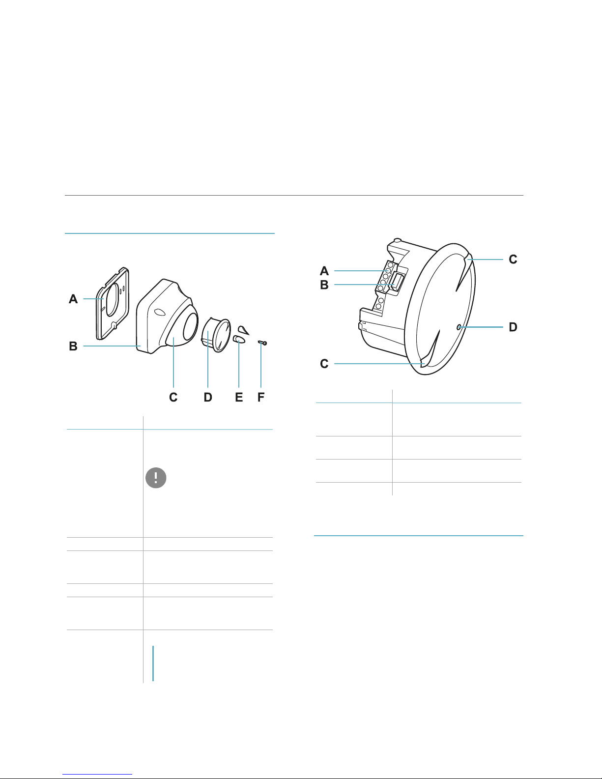
Main components
Part Description
A Perforated housing base for
adaptation to the main
junction boxes
IMPORTANT: the base of
the container is, together
with the two fastening
screws (not provided),
an integral partof the
sensor anti-removal and
anti-tear system.
B Sensor housing
C Adjustable support for the
sensor with integrated
fastening screws
D Sensor
E Caps to cover the fastening
screws of the adjustable
support
F Box-base fastening screw
Note: the container-base
fastening screw is not a part of
the sensor anti-removal and
anti-tear system.
Sensor
Part Description
A Terminal block for
connecting power supply and
four relays
B Connector for connecting the
dongle
C Sensor plane indicators
(horizontal or vertical)
D LED
Applications
Types of applications
The sensor is suitable for indoor and outdoor
installations and can be mounted on the wall or
ceiling.
According to the direction, the sensor can be:
l a volumetric sensor to monitor a large area
(horizontal direction).
l barrier sensor to monitor a perimeter area,
creating a protective barrier against access
along a wall or gate (vertical direction).
Page 5
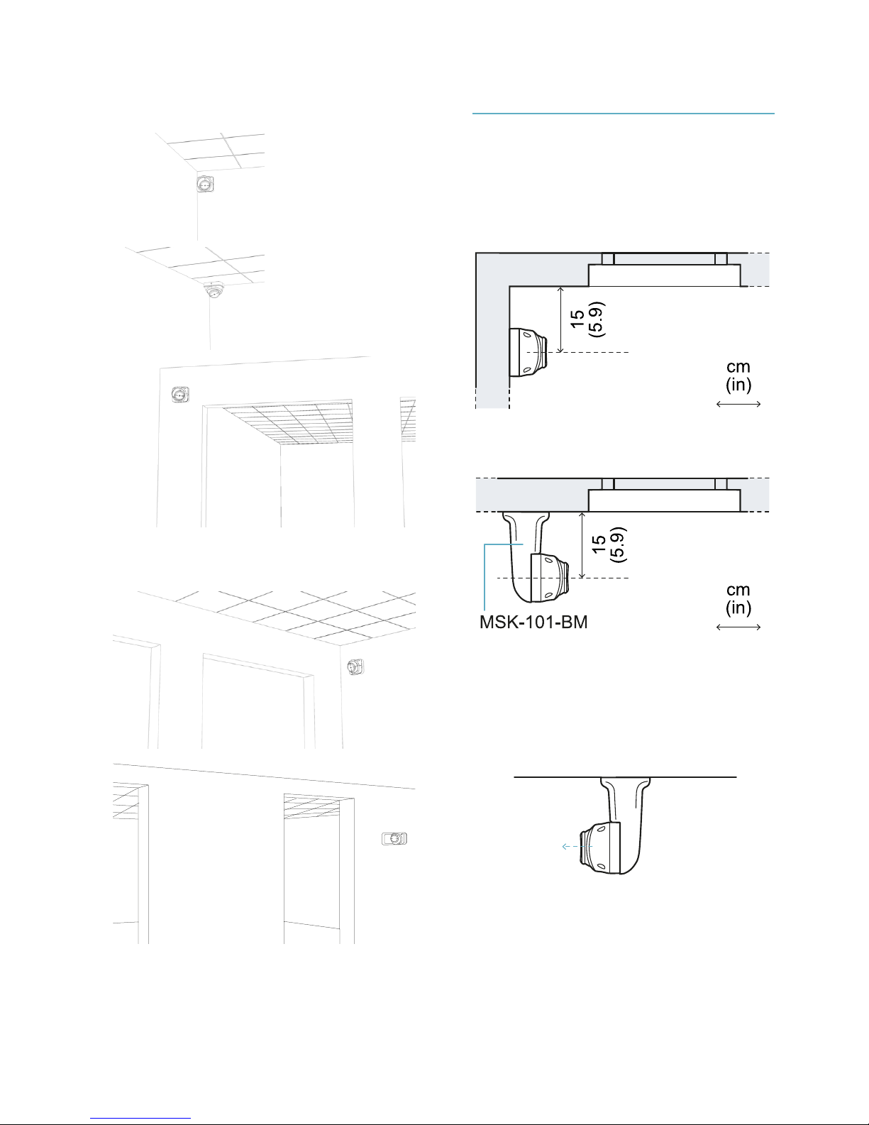
Examples of volumetric sensor
installation
Examples of barrier sensor
installation
Barrier configuration
Adapter for barrier assembly
Barrier installation for protection of a wall or
window requires the sensor to be installed at
approximately 15 cm (5.9 in) from the same wall.
If other adequate supports are not available, an
adapter is necessary for assembling the barrier
(product code: MSK-101-BM.
Figure 1- Example of installation without adapter.
Figure 2- Example of installation with MSK-101-BM adapter.
Sensor direction
The MSK-101-BM adapter, according to the
installation method, allows directing the sensor
to the right or the left.
Figure 3- Sensor directed towards the right.
Get to know MSK-101
MSK-101| Installation instructions v1.0 FEB 2018 |msk-101_instructions_en_wo v1.0|© 2017-2018 Inxpect SpA
5
Page 6
6
MSK-101| Installation instructions v1.0 FEB 2018 |msk-101 _i nstructions_en_wo v1.0|© 2017-2018 Inxpect SpA
Get to know MSK-101
Figure 4- Sensor directed towards the left.
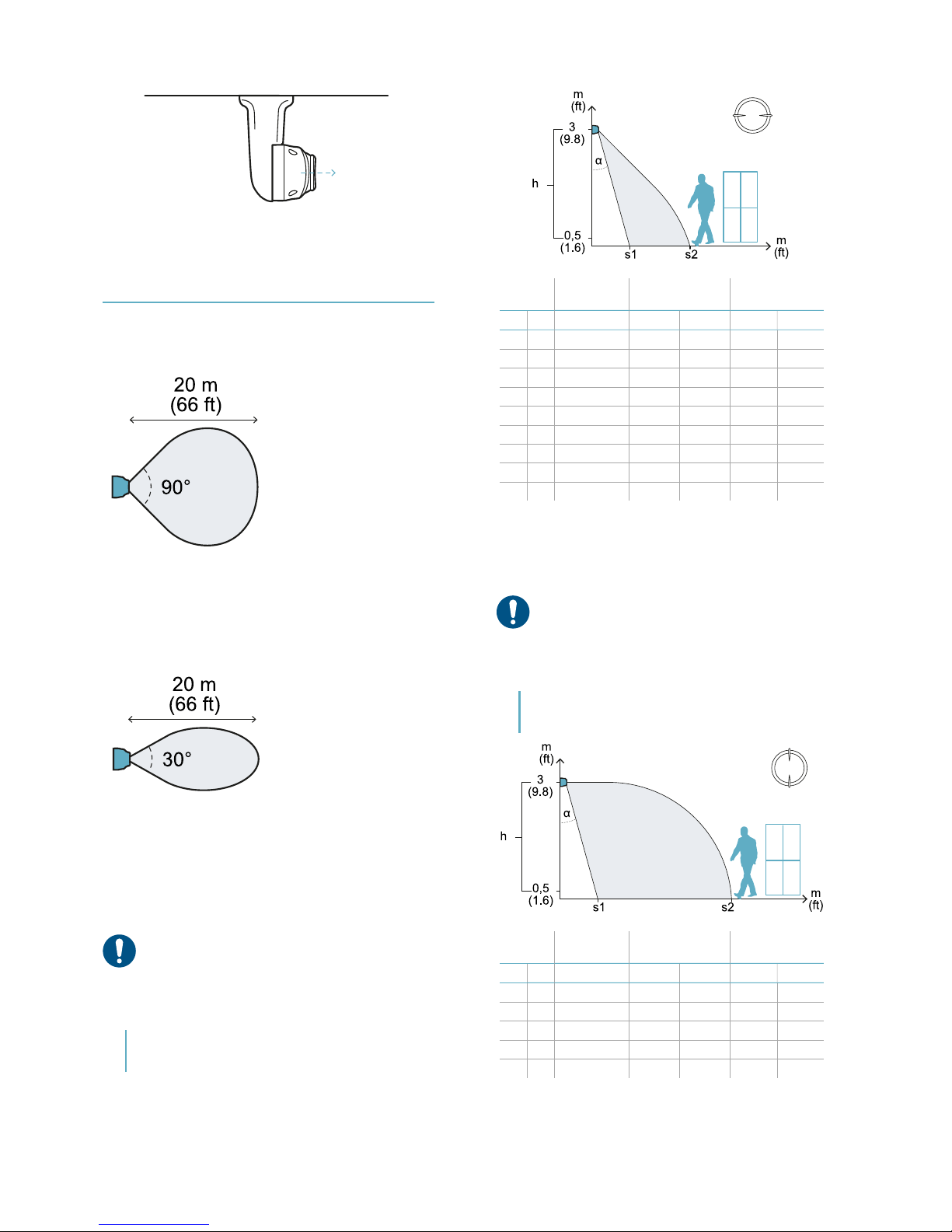
Field of vision
Range of the field with horizontal
sensor direction (volumetric)
Figure 5- Seen from top view.
Range of the field with vertical
sensor direction (barrier)
Figure 6- Seen from top view.
Examples of the field of vision
with horizontal sensor direction
(volumetric)
NOTICE: the detection start and end values do not
guarantee detection of a standing person. The
reported values may slightly vary based on the
installation conditions. Check the effective
monitored area through the application during
configuration.
Note: only some heights are reported, but every
intermediate value is allowed and guarantees optimum
performance.
Height
(h)
Inclination
(α)
Start detection
(s1)
End detection
(s2)
m ft m ft m ft
1 3.2 0° 0.5 1.6 20 65
1.5 4.9 0° 0.5 1.6 20 65
2 6.5 -15° 2.5 8.2 16 52
2 6.5 -30° 2 6.5 10 32
2.5 8.2 -15° 3 9.8 17 55
2.5 8.2 -30° 2.5 8.2 10 32
2.5 8.2 -45° 2 6.5 6.5 21
3 10 -30° 2.5 8.2 10 32
3 10 -45° 2 6.5 6.5 21
Examples of the field of vision
with vertical sensor direction
(barrier)
NOTICE: the detection start and end values do not
guarantee detection of a standing person. The
reported values may slightly vary based on the
installation conditions. Check the effective
monitored area through the application during
configuration.
Note: only some heights are reported, but every
intermediate value is allowed and guarantees optimum
performance.
Height
(h)
Inclination
(α)
Start detection
(s1)
End detection
(s2)
m ft m ft m ft
1 3.2 0° 0.5 1.6 20 65
1.5 4.9 0° 0.5 1.6 20 65
2 6.5 -15° 2 6.5 20 65
2 6.5 -30° 1 3.2 16 52.5
2.5 8.2 -15° 2 6.5 20 65
Page 7
Height
(h)
Inclination
(α)
Start detection
(s1)
End detection
(s2)
m ft m ft m ft
2.5 8.2 -30° 1 3.2 20 65
2.5 8.2 -45° 1 3.2 18 59
3 10 -15° 2 6.5 20 65
3 10 -30° 1 3.2 20 65
3 10 -45° 1 3.2 15 49
Interferences
Introduction
The MSK-101 sensor is different from other
traditional motion sensors. It is important to
know what factors interfere in its correct
functioning, to properly install, configure it, and
to obtain optimum performance; for detailed
information see Advanced configuration manual.
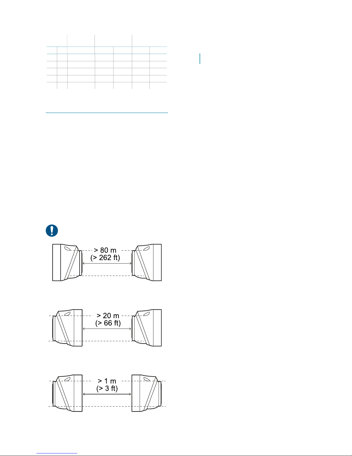
How to install several sensors
Three possible combinations of sensor
installation and the minimum distances to
maintain between the sensors with the sensors
aligned are presented as follows. Respecting
these distances guarantees the performance
levels indicated in section "Field of vision" on the
previous page.
NOTICE: other combinations are possible, but their
performance must be validated in the field.
Figure 7- Front-front combination
Figure 8- Front-back combination
Figure 9- Back-back combination
Note: the blind spot created in this combination is very
wide. If possible, use the back-front configuration.
Get to know MSK-101
MSK-101| Installation instructions v1.0 FEB 2018 |msk-101_instructions_en_wo v1.0|© 2017-2018 Inxpect SpA
7
Page 8
8
MSK-101| Installation instructions v1.0 FEB 2018 |msk-101 _i nstructions_en_wo v1.0|© 2017-2018 Inxpect SpA
2
Installation and use procedures
Installation and
configuration
Necessary components and tools
l Wi-Fi dongle (product code: WSYNC-RJ-WIFI or
WSYNC-RJ-WIFI-US).
l Android or iOS device with Wi-Fi enabled and
the Inxpect Security application installed, see
"MSK-101" on page4.
IMPORTANT: to ensure correct functioning,
allow all requested permissions for the
application.
l Only for barrier applications and if necessary,
adapter for assembly (product code: MSK-101BM) (see "Barrier configuration" on page5).
l Screwdriver, wire stripper and fastening tools
not provided.
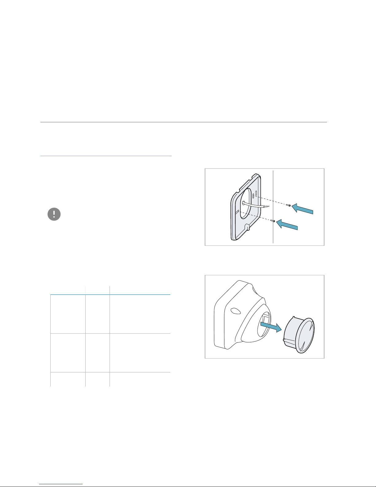
Install MSK-101
1. Assemble the sensor:
For... And... See...
barrier
applications
with
adapter
MSK-101BM
sensor
directed
to the
left
"Assemble the sensor
with the MSK-101-BM
adapter (sensor
directed to the left)"
on the next page
barrier
applications
with
adapter
MSK-101BM
sensor
directed
to the
right
"Assemble the sensor
with the MSK-101-BM
adapter (sensor
directed to the left)"
on the next page
all other
cases
- "Assemble the
sensor" below
2. "Connect the sensor to the alarm control unit"
on page11.
3. "Direct and configure the sensor" on page11.
4. "Fasten the sensor" on page13.
Assemble the sensor
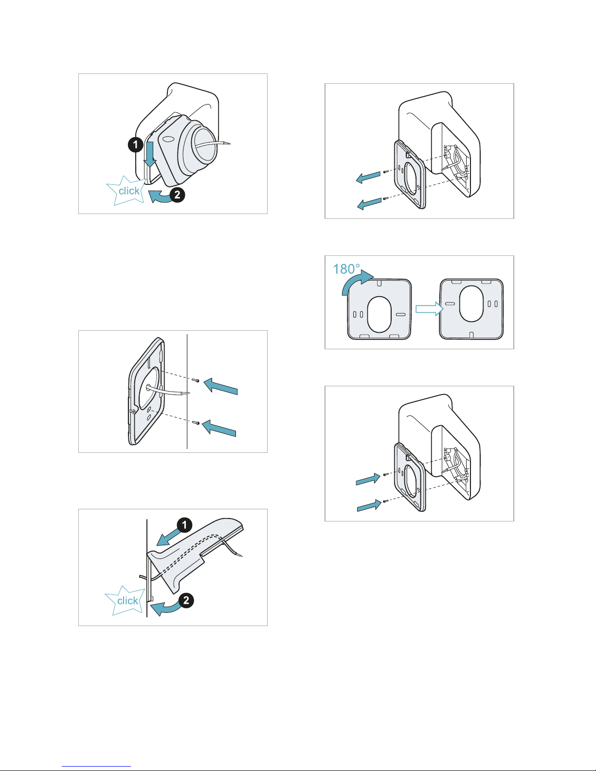
1. Using the prepared holes, fasten the base to
the wall or to the junction box with two screws
(not provided).
2. Extract the sensor from the adjustable
support.
Page 9
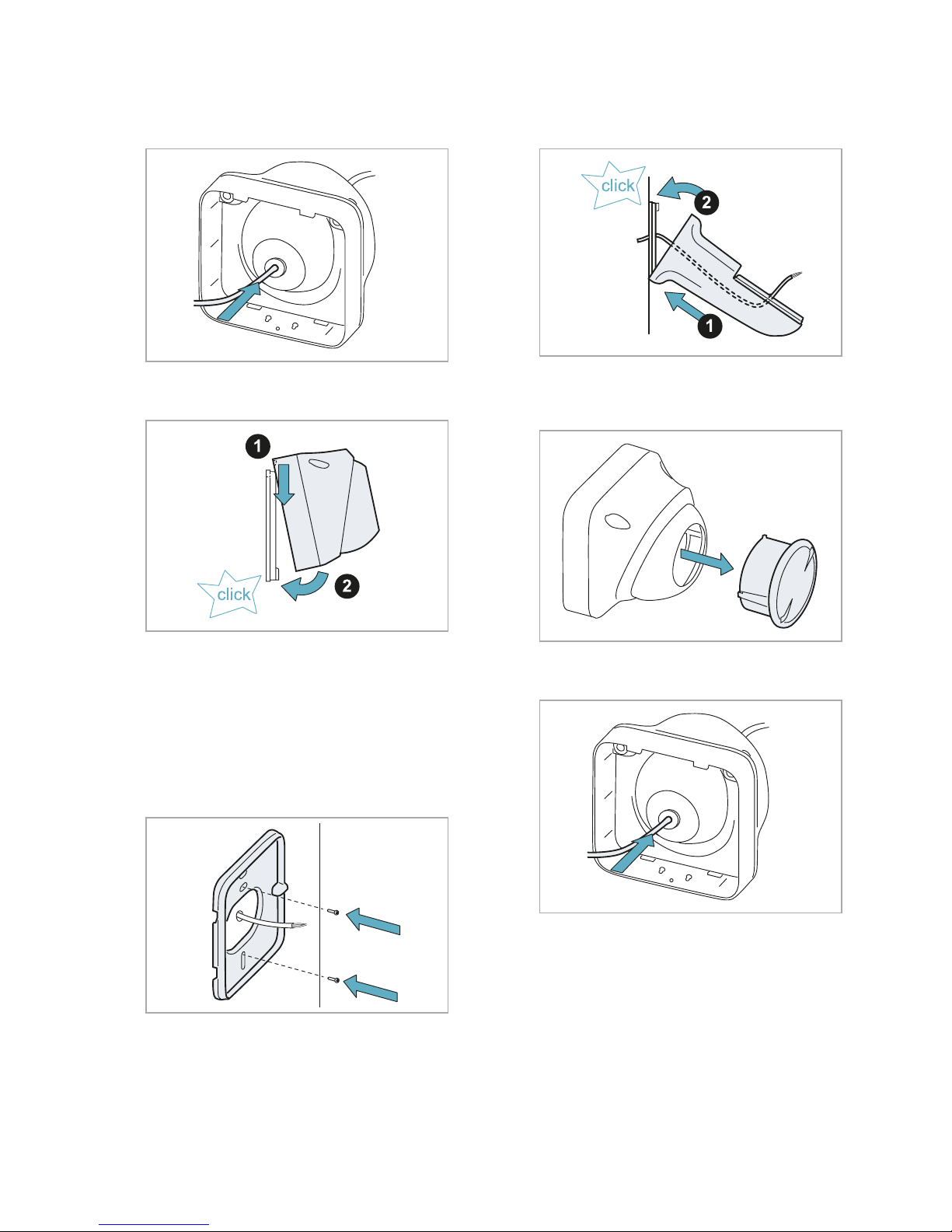
3. Pass the cable with the wires coming out of
the alarm control unit into the sensor
housing.
4. Fasten the sensor housing to the base.
Assemble the sensor with the
MSK-101-BM adapter (sensor
directed to the left)
1. Using the prepared holes, direct the base of
the sensor as shown in the figure and fasten it
to the wall or to the junction box with two
screws (not provided).
2. Assemble the adapter to the base, passing the
cable with the wires coming out of the alarm
control unit into the adapter.
3. Extract the sensor from the adjustable
support.
4. Pass the cable into the sensor housing.
Installation and use procedures
MSK-101| Installation instructions v1.0 FEB 2018 |msk-101_instructions_en_wo v1.0|© 2017-2018 Inxpect SpA
9
Page 10
10
MSK-101| Installation instructions v1.0 FEB 2018 |msk-101 _i nstructions_en_wo v1.0|© 2017-2018 Inxpect SpA
Installation and use procedures
5. Assemble the sensor housing to the adapter.
Assemble the sensor with the
MSK-101-BM adapter (sensor
directed to the right)
1. Using the prepared holes, direct the base of
the sensor as shown in the figure and fasten it
to the wall or to the junction box with two
screws (not provided).
2. Assemble the adapter to the base, passing the
cable with the wires coming out of the alarm
control unit into the adapter.
3. Unscrew the fastening screws on the preassembled base of the adapter.
4. Turn the base 180°.
5. Tighten the screws.
Page 11
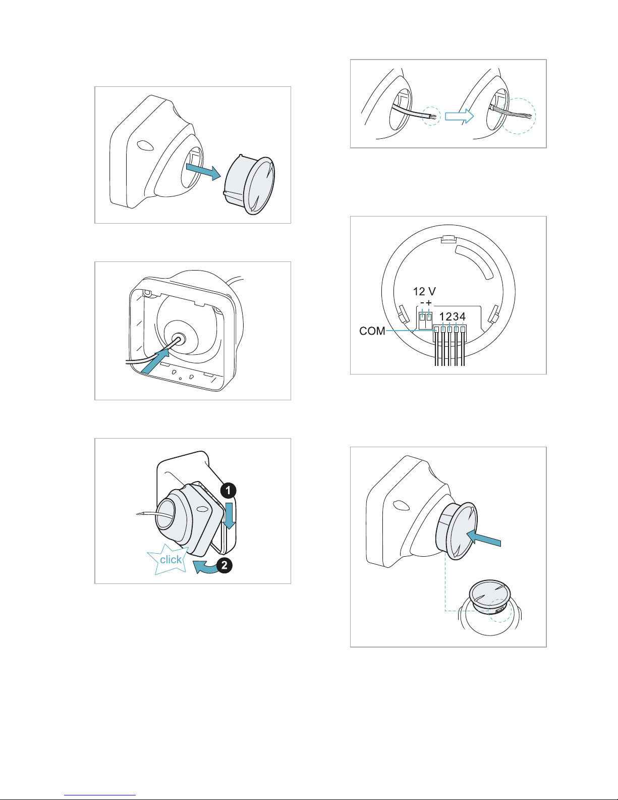
6. Extract the sensor from the adjustable
support.
7. Pass the cable into the sensor housing.
8. Assemble the sensor housing to the adapter.
Connect the sensor to the alarm
control unit
1. Remove the sheath and the hose by at least 5
cm (2 in).
2. Connect the power supply and relay outputs.
It is recommended to connect relay 3
(tampering) and 4 (fault) to a 24 h line from
the alarm control unit.
Direct and configure the sensor
1. Insert the sensor into the adjustable support,
leaving the connector in sight.
Installation and use procedures
MSK-101| Installation instructions v1.0 FEB 2018 |msk-101_instructions_en_wo v1.0|© 2017-2018 Inxpect SpA
11
Page 12
12
MSK-101| Installation instructions v1.0 FEB 2018 |msk-101 _i nstructions_en_wo v1.0|© 2017-2018 Inxpect SpA
Installation and use procedures
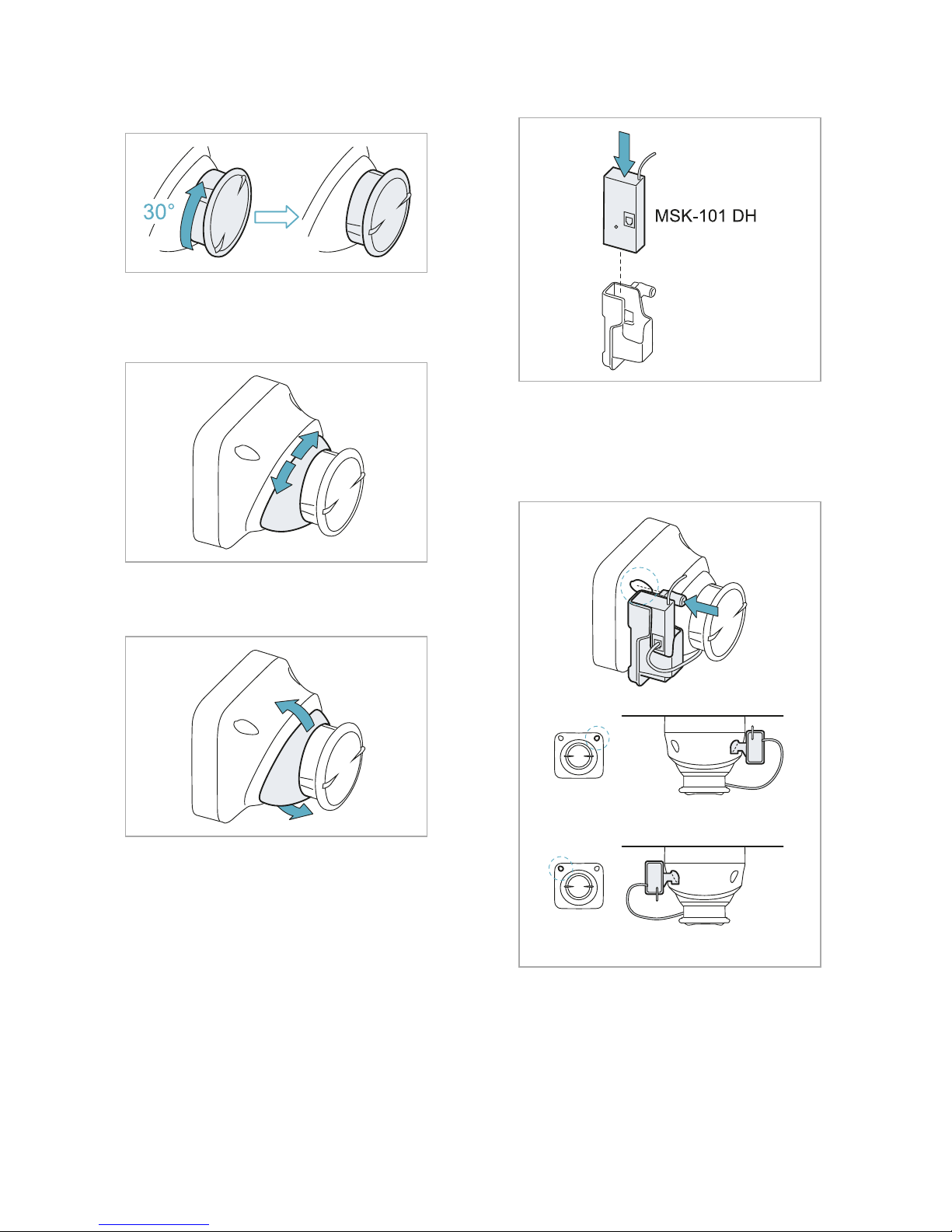
2. Turn the sensor to lock it into the adjustable
support.
3. Turn the adjustable support to arrange the
sensor direction vertically (barrier application)
or horizontally (volumetric application).
4. Tilt down the adjustable support to reach the
desired sensor inclination.
5. Insert the dongle into its caddy.
6. Connect the dongle and fasten it to the
sensor. For 45° sensor inclinations
downwards, see "45° downward inclination" on
the facing page It can be fastened to the right
or left of the sensor.
Page 13
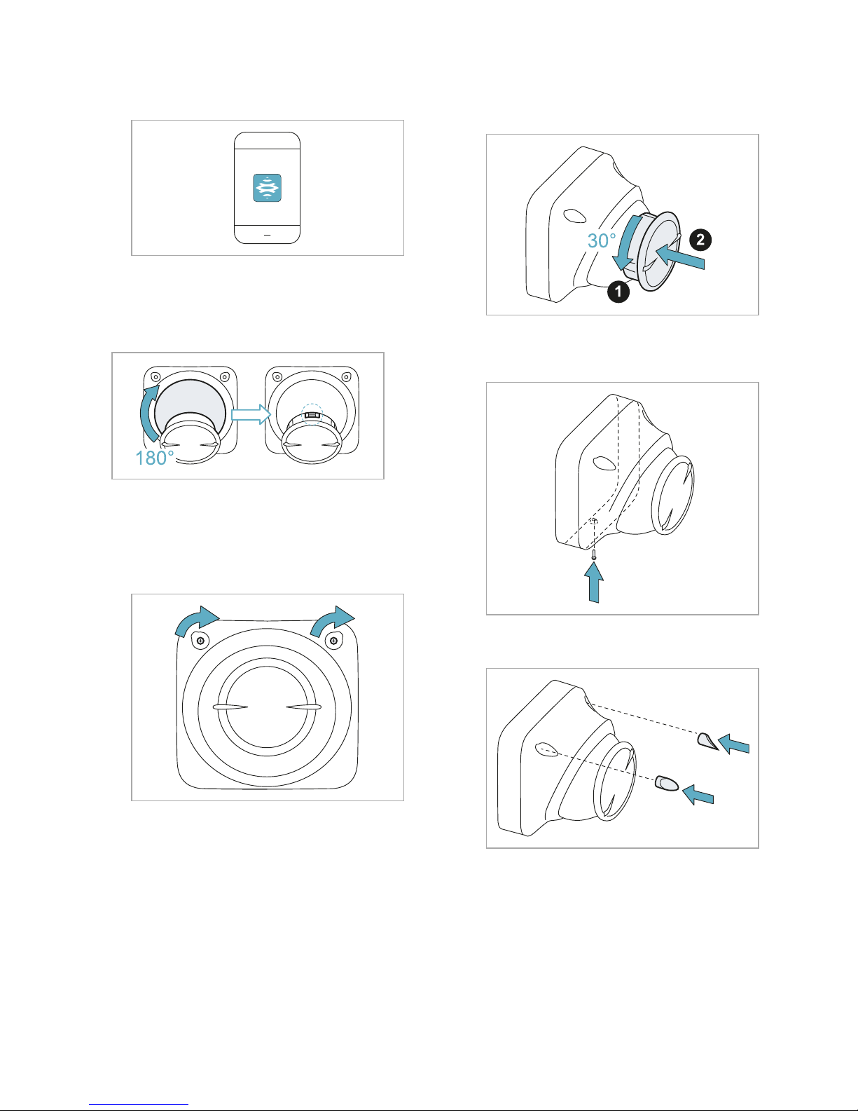
7. Use the Inxpect Security application to
configure the sensor.
45° downward inclination
To make the connector for connecting the dongle
accessible, turn the adjustable support by 180°.
Fasten the sensor
1. Tighten the screws to fasten the adjustable
support. Check in the application that the
adjustable support has not moved.
2. Disconnect the dongle. Hold the adjustable
support firmly and completely insert the
sensor.
3. Fasten the body of the sensor to the base
using the provided screw.
4. Insert the provided caps.
Installation and use procedures
MSK-101| Installation instructions v1.0 FEB 2018 |msk-101_instructions_en_wo v1.0|© 2017-2018 Inxpect SpA
13
Page 14
14
MSK-101| Installation instructions v1.0 FEB 2018 |msk-101 _i nstructions_en_wo v1.0|© 2017-2018 Inxpect SpA
3
Appendix
Technical data
Detection
method
Inxpect movement detection
motor based on FMCW radar
Frequency Working band: 24–24.25 GHz
Transmission power: ≤ 13 dBm
Modulation: FMCW
Detection
interval
From 0.5 to 20 m (from 2 to 66
ft), depending on the installation
conditions. Configurable in 30 cm
(1 ft) increments.
Field of
vision
Sensor horizontal plane: 90°
Sensor vertical plane: 30°
Height: from 0.5 to 3 m (from 1.6
to 10 ft)
Detection
speed
> 0.05 ms (2 in/s)
Relays 4 solid state relays, each max.
400 mA, 60 V dc (NO or NC
configurable, default NC)
Power supply 12 V dc ± 25% *
Absorption max. 100 mA
Electrical
protections
Inverted polarity
Overcurrent through integrated
fuse (max. 5 s @ 3 A)
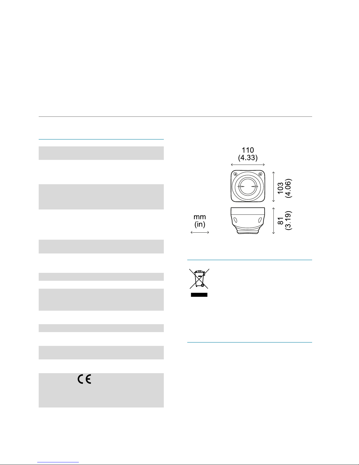
Dimensions 103 x 110 x 81 mm (4.06 x 4.33 x
3.19 in)
Material Technopolymer
Operating
temperature
From -40 to +70 °C (from -40 to
+158 °F)
Degree of
protection
IP67
Cable
diameter
4–7 mm (0.16–0.27 in)
Approvals
Contains FCC ID: UXS-SMR-3X4
Compatible with EN50131-2-3
class IV grade 3 and UL639
Note *: the device has been designed to be
supplied by an external power supply unit for
alarm systems, internally protected by a shortcircuit.
Disposal
The product must be disposed of at
the relative recycling centers specified
by the government or local public
authorities.
Correct disposal and recycling will
contribute to the prevention of
potentially harmful consequences to
the environment and population.
Conformity and restrictions
Consultation of certifications
All updated certifications are available on the
website:www.inxpect.com/security/documents.
EC declaration of conformity
The manufacturer, Inxpect SpA, declares that the
type of radio equipment MSK-101 complies with
the directive 2014/53/EU. The full EU declaration
of conformity text is available on the following
website: www.inxpect.com/security/documents.
Page 15
FCC Certification
MSK-101 complies with FCC CFR Title 47 Part 15
Subpart B. It contains FCC ID UXS-SMR-3X4.
Operation is subject to the following two
conditions:
l this device may not cause harmful
interference, and
l this device must accept any interference
received, including interference that may cause
undesired operation.
NOTICE: changes or modifications made to this
equipment and not explicitly approved by Inxpect
SpA may void the FCC authorization to operate this
equipment.
National restrictions
MSK-101 is a short range device in class 2 in
accordance with the directive 2014/53/EU (RED Radio equipment and telecommunications
terminal equipment) and is subject to the
following restrictions:
UK FR
Restrictions in UK: it is strictly forbidden to use
MSK-101 in United Kingdom, because the
national allocation of frequencies does not allow
the free use of the whole band 24-24.25 GHz.
Restrictions en FR: il est strictement interdit
d'utiliser MSK-101 en France, car la répartition
nationale des fréquences ne permet pas la libre
utilisation de la bande entière 24-24,25 GHz.
Service and warranty
Customer service
TSec SpA
Traversa di via Gavardina, 74
25081 Bedizzole (BS) - Italy
Tel: +39 030 57 85 302
Fax: +39 012 3456789
e-mail: [email protected]
website: www.tsec.it
How to return the product
If necessary, pay to ship the product in its
original packaging to the area distributor, or
directly to the exclusive distributor.
Area distributor
Exclusive distributor for
Europe
Note distributor information
here:
TSec SpA
Traversa di via
Gavardina, 74
25081 Bedizzole (BS)
Italy
T. +39 030 57 85 302
F. +39 012 3456789
[email protected]
www.tsec.it
Service and warranty
To find out about the terms of the warranty,
exclusions and cancellation of the warranty, refer
to the website https://www.tsec.it/it/condizionidi-vendita.php.
Download
Download the application
www.inxpect.com/stores.php
Appendix
MSK-101| Installation instructions v1.0 FEB 2018 |msk-101_instructions_en_wo v1.0|© 2017-2018 Inxpect SpA
15
Page 16

MSK-101
Installation instructions v1.0
FEB 2018
msk-101_instructions_en_wo v1.0
Copyright © 2017-2018 Inxpect SpA
Exclusive distributor for Europe:
TSec SpA
Traversa di via Gavardina, 74
25081 Bedizzole (BS)
Italy
www.tsec.it
+39 030 57 85 302
Manufacturer:
Inxpect SpA
Via del Serpente, 89
25131 Brescia (BS)
Italy
www.inxpect.com
+39 030 254 0300
 Loading...