

MSK-101-MM
Intelligent motion sensor
Installation instructions
v1.7 - EN
Carefully read this manual in its entirety.
You will find useful information to take full advantage of the product's potential, use it safely and obtain the best results.

Copyright © 2017-2018, Inxpect SpA
All rights reserved in all countries.
Any distribution, alteration, translation or reproduction, partial or total, of this
document is strictly prohibited unless with prior authorization in writing from
Inxpect SpA, with the exception of the following actions:
l Printing the document in its original format, totally or partially.
l Transferring the document on websites or other electronic systems.
l Copying contents without any modification and stating Inxpect SpA as
copyright owner.
Inxpect SpA reserves the right to make modifications or improvements to the
relative documentation without prior notice.
Requests for authorization, additional copies of this manual or technical
information on the latter, must be addressed to:
Inxpect SpA
Via del Serpente, 91
25131 Brescia (BS)
Italy
security@inxpect.com
+39 030 5785105
Contents
Get to know MSK-101-MM 5
MSK-101-MM 5
Applications 5
Barrier configuration 7
Field of vision 8
Interferences 9
Installation and use 11
Before installation 11
Install and configure the sensor 12
Appendix 18
Technical data 18
Disposal 18
Conformity and restrictions 19
Service and warranty 19
Download 19
Useful conventions for requesting assistance 20
Perforated base dimensions 21
MSK-101-MM| Installation i nstructions v1.7 OCT 2018 |msk-101-mm_instructions_en_us v1.7|© 2017-2018 Inxpect SpA
iii
Instruction updates
Publication
date
OCT 2018 msk-101-mm_instructions_en_
us v1.7
AUG 2018 msk-101_advanced_config_en_
us v1.6
MAY 2018 msk-101_advanced_config_en_
us v1.5
APR 2018 msk-101_instructions_en_us
v1.4
MAR 2018 msk-101_instructions_en_us
v1.3
FEB 2018 msk-101_instructions_en_us
v1.2
JAN 2018 msk-101_instructions_en_us
v1.0
Code Updates
Modified United Kingdom and France national restrictions
Integrated examples of field of vision with animal tolerance
limit
Corrected field of vision corner dimensions
Added list of interfering materials
Integrated calibration (automatic and manual)
Other minor changes
UL certification
Modified dongle connection illustration
Modified relay voltage
Specified interference with neon tubes
Corrected illustrations of examples of the field of vision
Specified need for shielded cable
Modified and completed application illustrations
Added chapter "Useful conventions for requesting
assistance" on page20
Added perforated base dimensions
Added barrier assembly accessory (MSK-101-BM)
Added Dongle caddy accessory (MSK-101-DH)
First publication
Provided documentation
Document Code Date
Installation instructions (this
manual)
Advanced configuration manual msk-101-mm_advanced-config_en_us
msk-101-mm_instructions_en_us v1.7 OCT
v1.7
2018
OCT
2018
Distribution
format
PDF online
online manual
PDF online
iv
MSK-101-MM| Installation i nstructions v1.7 OCT 2018 |msk-101-mm_instructions_en_us v1.7|© 2017-2018 Inxpect SpA
1
Get to know MSK-101-MM
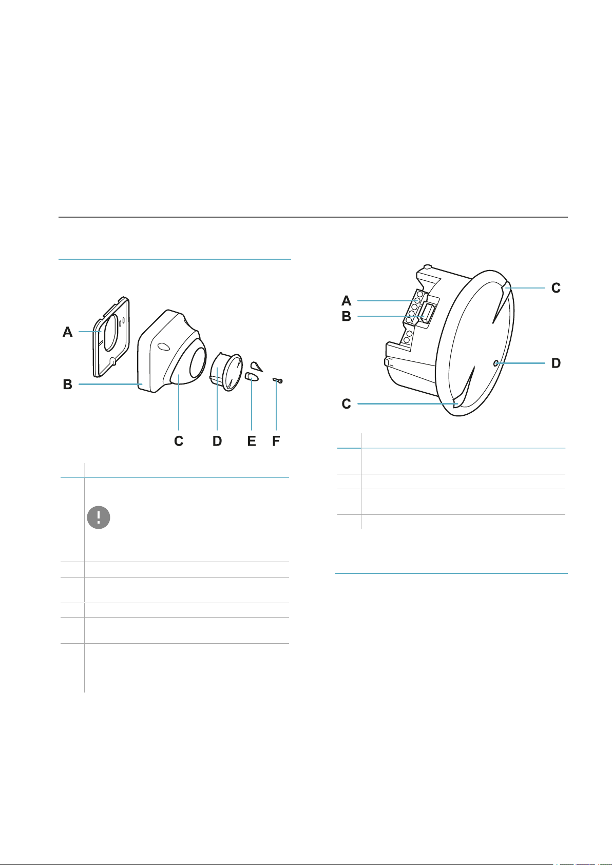
MSK-101-MM
Main components
Part Description
A Perforated housing base for adaptation to
the main junction boxes
IMPORTANT: the base of the
container is, together with the two
fastening screws (not provided), an
integral part of the sensor antiremoval and anti-tear system.
B Sensor housing
C Adjustable support for the sensor with
integrated fastening screws
D Sensor
E Caps to cover the fastening screws of the
adjustable support
F Box-base fastening screw
Note: the container-base fastening screw is not
a part of the sensor anti-removal and anti-tear
system.
Sensor
Part Description
A Terminal block for connecting power
supply and four relays
B Connector for connecting the dongle
C Sensor plane indicators (horizontal or
vertical)
D LED
Applications
Types of applications
The sensor is suitable for indoor and outdoor
installations and can be mounted on the wall or
ceiling.
According to the direction, the sensor can be:
l a volumetric sensor to monitor a large area
(horizontal direction).
l barrier sensor to monitor a perimeter area,
creating a protective barrier against access
along a wall or gate (vertical direction).
MSK-101-MM| Installation i nstructions v1.7 OCT 2018 |msk-101-mm_instructions_en_us v1.7|© 2017-2018 Inxpect SpA
5
Get to know MSK-101-MM
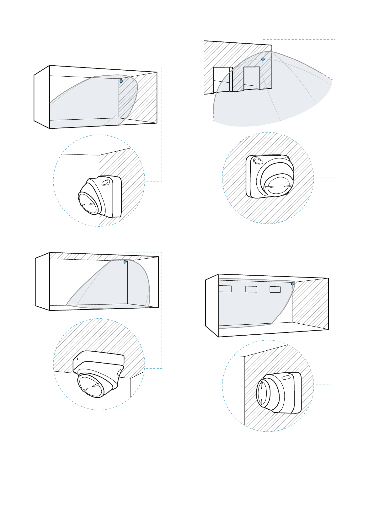
Examples of volumetric sensor
installation
Indoor wall installation.
Outdoor installation.
Examples of barrier sensor
installation
Indoor ceiling installation.
6
MSK-101-MM| Installation i nstructions v1.7 OCT 2018 |msk-101-mm_instructions_en_us v1.7|© 2017-2018 Inxpect SpA
Indoor wall installation.
Get to know MSK-101-MM
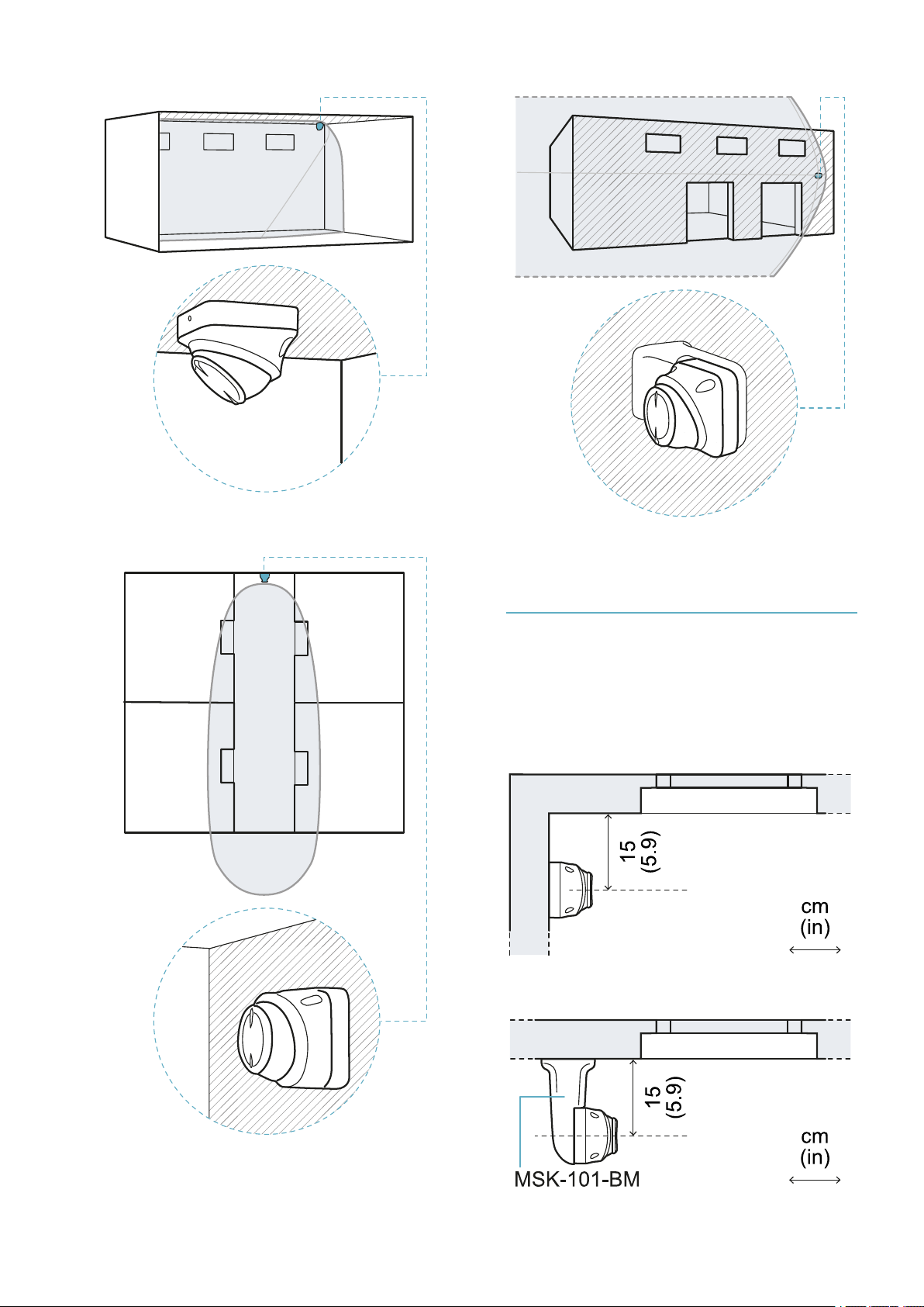
Indoor ceiling installation.
Outdoor installation with adapter.
Barrier configuration
Adapter for barrier assembly
Barrier installation for protection of a wall or
window requires the sensor to be installed at
approximately 15 cm (5.9 in) from the same wall.
If other adequate supports are not available, an
adapter is necessary for assembling the barrier
(product code: MSK-101-BM.
Example of installation without adapter.
Indoor hallway installation.
MSK-101-MM| Installation i nstructions v1.7 OCT 2018 |msk-101-mm_instructions_en_us v1.7|© 2017-2018 Inxpect SpA
7

Get to know MSK-101-MM
Example of installation with MSK-101-BM adapter.
Sensor direction
The MSK-101-BM adapter, according to the
installation method, allows directing the sensor to
the left or the right.
Sensor directed towards the left.
Side view.
Range of the field with vertical
sensor direction (barrier)
Top view.
Sensor directed towards the right.
Field of vision
Range of the field with horizontal
sensor direction (volumetric)
Top view.
Side view.
Calculation of the field of vision
The actual field of vision of the sensor (detection
start and end - s1e s3) depends on:
l sensor installation height (h)
l sensor direction (horizontal or vertical)
l sensor inclination (α)
Within the field of vision, discernment of animals is
guaranteed up to a certain distance from the
sensor (s2). Per dettagli sulla discriminazione
degli animali, fare riferimento al manuale di
configurazione avanzata.
Based on a specific installation height, there are
direction and inclination combinations that
guarantee optimum performance. Some
examples to better explain the effects of height
and inclination are presented as follows.
8
MSK-101-MM| Installation i nstructions v1.7 OCT 2018 |msk-101-mm_instructions_en_us v1.7|© 2017-2018 Inxpect SpA

Get to know MSK-101-MM
Examples of the field of vision with
horizontal sensor direction
(volumetric)
NOTICE: the detection start and end values do not
guarantee detection of a standing person. The
reported values may slightly vary based on the
installation conditions.
Note: only some heights are reported, but every
intermediate value is allowed and guarantees optimum
performance.
The dimensions of the field of vision expressed in
meters and feet are as follows.
h (m) α (°)
1 0 0.5 * 20
1.5 0 0.5 20 20
2 -15 2.5 16 16
2 -30 2 7.5 10
2.5 -15 3 17 17
2.5 -30 2.5 7 10
2.5 -45 2 6.5 6.5
3 -30 2.5 7 10
3 -45 2 4.5 6.5
s1(m) s2(m) s3(m)
h (m) α (°)
2 -15 2 20 20
2 -30 1 16 16
2.5 -15 2 20 20
2.5 -30 1 20 20
2.5 -45 1 16 18
3 -15 2 20 20
3 -30 1 20 20
3 -45 1 12 15
h (ft) α (°)
3.2 0 1.6 * 65
4.9 0 1.6 20 65
6.5 -15 6.5 20 65
6.5 -30 3.2 16 52
8.2 -15 6.5 20 65
8.2 -30 3.2 20 65
8.2 -45 3.2 16 59
10 -15 6.5 20 65
10 -30 3.2 20 65
10 -45 3.2 12 49
s1(m) s2(m) s3(m)
s1(ft) s2(ft) s3(ft)
h (ft) α (°)
3.2 0 1.6 * 65
4.9 0 1.6 65 65
6.5 -15 8.2 52 52
6.5 -30 6.5 25 32
8.2 -15 9.8 55 55
8.2 -30 8.2 23 32
8.2 -45 6.5 21 21
10 -30 8.2 23 32
10 -45 6.5 15 21
Note *: discernment of animals is not guaranteed in the
entire field of vision.
s1(ft) s2(ft) s3(ft)
Examples of the field of vision with
vertical sensor direction (barrier)
NOTICE: the detection start and end values do not
guarantee detection of a standing person. The
reported values may slightly vary based on the
installation conditions.
Note: only some heights are reported, but every
intermediate value is allowed and guarantees optimum
performance.
The dimensions of the field of vision expressed in
meters and feet are as follows.
Note *: discernment of animals is not guaranteed in the
entire field of vision.
Interferences
Introduction
The MSK-101-MM sensor is different from other
traditional motion sensors. It is important to know
what factors interfere in its correct functioning, to
properly install, configure it and to obtain
optimum performance, per informazioni
dettagliate vedi Manuale di configurazione
avanzata.
Interference with neon tubes
In the presence of neon tubes, respect the
minimum sensor inclination indicated so that the
tube does not interfere with the sensor:
Sensor direction Minimum inclination (α)*
Horizontal - 15°
Vertical - 30°
Note *: see "Examples of the field of vision with
horizontal sensor direction (volumetric)" above and
"Examples of the field of vision with vertical sensor
direction (barrier)" above.
h (m) α (°)
1 0 0.5 * 20
1.5 0 0.5 20 20
MSK-101-MM| Installation i nstructions v1.7 OCT 2018 |msk-101-mm_instructions_en_us v1.7|© 2017-2018 Inxpect SpA
s1(m) s2(m) s3(m)
9

Get to know MSK-101-MM
Interfering materials
Below is a list of materials that could impact the
sensor performance if they hide it:
l surfaces having metal-based paints or
carbon-based paints
l tinted windows
l surfaces having EMI/RFI glasses or mirrors
l surfaces with water pipes, cables
l tiles having metal-based glaze including
blue cobalt
l metal screen foil
l foil-backed insulation materials (e.g. foil)
l foil moist materials (e.g. cork)
How to install several sensors
Three possible combinations of sensor
installation and the minimum distances to
maintain between the sensors with the sensors
aligned are presented as follows. Respecting
these distances guarantees the performance
levels indicated in section "Field of vision" on
page8.
NOTICE: other combinations are possible, but their
performance must be validated in the field.
Front-front combination
Front-back combination
Back-back combination
Note: the blind spot created in this combination is very
wide. If possible, use the back-front configuration.
10
MSK-101-MM| Installation i nstructions v1.7 OCT 2018 |msk-101-mm_instructions_en_us v1.7|© 2017-2018 Inxpect SpA

Installation and use
2
Before installation
Necessary components and tools
l Wi-Fi dongle (product code: WSYNC-RJ-
WIFI or WSYNC-RJ-WIFI-US).
l Android or iOS device with Wi-Fi enabled
and the Inxpect Security application
installed (see "MSK-101-MM" on page5).
IMPORTANT: to ensure correct
functioning, allow all requested
permissions for the application.
l Only for barrier applications and if
necessary, adapter for assembly (product
code: MSK-101-BM) (see "Barrier
configuration" on page7).
l Two screws up to M4 (No.6) for fastening to
the wall or to the junction box.
l Screwdriver, wire stripper and fastening
tools not provided.
Prepare for installation
NOTICE: to ensure effective functioning, the
sensor must be installed in the best possible
position and configured correctly. Carefully follow
the instructions below.
Before installing the sensor, perform the following
operations:
1. Define the sensor application type (see
"Applications" on page5).
2. Define the installation position, considering
possible interferences (see "Interferences" on
page9).
3. Define the height of installation for the sensor
to obtain the desired field of vision (see "Field
of vision" on page8).
4. Run a shielded cable with the necessary
conductors from the alarm control unit to
connect the sensor (power supply and relay
outputs).
5. Only for installations with MSK-101-BM
adapter, define the direction of the sensor
(see "Barrier configuration" on page7).
Install MSK-101-MM
1. Assemble the sensor:
For... And... See...
barrier
applications
with
adapter
MSK-101BM
barrier
applications
with
adapter
MSK-101BM
all other
cases
2. "Connect the sensor to the alarm control unit"
on page14.
3. "Direct the sensor" on page15.
4. " Connect the dongle and configure the
sensor" on page15 .
5. "Fasten the sensor" on page16.
sensor
directed
to the
right
sensor
directed
to the
left
- "Assemble the
"Assemble the
sensor with the MSK101-BM adapter
(sensor directed to
the right)" on the next
page
"Assemble the
sensor with the MSK101-BM adapter
(sensor directed to
the left)" on page13
sensor" on the next
page
Warnings
NOTICE: damage to the device. Do not let dust or
water near the sensor during installation.
MSK-101-MM| Installation i nstructions v1.7 OCT 2018 |msk-101-mm_instructions_en_us v1.7|© 2017-2018 Inxpect SpA
11

Installation and use
Install and configure the sensor
Assemble the sensor
1. Using the prepared holes, fasten the base to
the wall or to the junction box with two screws
(not provided). See "Perforated base
dimensions" on page21.
2. Extract the sensor from the adjustable
support.
4. Fasten the sensor housing to the base.
Assemble the sensor with the
MSK-101-BM adapter (sensor
directed to the right)
1. Using the prepared holes, direct the base of
the sensor as shown in the figure and fasten it
to the wall or to the junction box with two
screws (not provided). See "Perforated base
dimensions" on page21.
3. Pass the cable with the wires coming out of
the alarm control unit into the sensor
housing.
2. Assemble the adapter to the base, passing the
cable with the wires coming out of the alarm
control unit into the adapter.
12
MSK-101-MM| Installation i nstructions v1.7 OCT 2018 |msk-101-mm_instructions_en_us v1.7|© 2017-2018 Inxpect SpA

Installation and use
3. Extract the sensor from the adjustable
support.
4. Pass the cable into the sensor housing.
Assemble the sensor with the
MSK-101-BM adapter (sensor
directed to the left)
1. Using the prepared holes, direct the base of
the sensor as shown in the figure and fasten it
to the wall or to the junction box with two
screws (not provided). See "Perforated base
dimensions" on page21.
2. Assemble the adapter to the base, passing the
cable with the wires coming out of the alarm
control unit into the adapter.
5. Assemble the sensor housing to the adapter.
3. Unscrew the fastening screws on the preassembled base of the adapter.
MSK-101-MM| Installation i nstructions v1.7 OCT 2018 |msk-101-mm_instructions_en_us v1.7|© 2017-2018 Inxpect SpA
13

Installation and use
4. Turn the base 180°.
5. Tighten the screws.
8. Assemble the sensor housing to the adapter.
Connect the sensor to the alarm
control unit
1. Remove the sheath and the hose by at least 5
cm (2 in).
6. Extract the sensor from the adjustable
support.
7. Pass the cable into the sensor housing.
2. Connect the power supply and relay outputs.
It is recommended to connect relay 3
(tampering) and 4 (fault) to a 24 h line from
the alarm control unit.
14
MSK-101-MM| Installation i nstructions v1.7 OCT 2018 |msk-101-mm_instructions_en_us v1.7|© 2017-2018 Inxpect SpA

Installation and use
Direct the sensor
1. Insert the sensor into the adjustable support,
leaving the connector in sight.
2. Turn the sensor to lock it into the adjustable
support.
4. Tilt down the adjustable support to reach the
desired sensor inclination.
Connect the dongle and configure
the sensor
1. Insert the dongle into its caddy.
3. Turn the adjustable support to orient the
sensor direction vertically (barrier application)
or horizontally (volumetric application).
MSK-101-MM| Installation i nstructions v1.7 OCT 2018 |msk-101-mm_instructions_en_us v1.7|© 2017-2018 Inxpect SpA
15

Installation and use
2. Connect the dongle and fasten it to the
sensor. For 45° sensor inclinations
downwards, see "45° downward inclination"
below. It can be fastened to the right or leftof
the sensor.
Fasten the sensor
1. Tighten the screws to fasten the adjustable
support. Check in the application that the
adjustable support has not moved.
2. Disconnect the dongle. Hold the adjustable
support firmly and completely insert the
sensor.
3. Use the Inxpect Security application to
configure the sensor.
45° downward inclination
To make the connector for connecting the dongle
accessible, turn the adjustable support by 180°.
3. Turn the sensor to bring it back to the
horizontal/vertical position.
16
MSK-101-MM| Installation i nstructions v1.7 OCT 2018 |msk-101-mm_instructions_en_us v1.7|© 2017-2018 Inxpect SpA

4. Fasten the body of the sensor to the base
using the provided screw.
5. Insert the provided caps.
Installation and use
MSK-101-MM| Installation i nstructions v1.7 OCT 2018 |msk-101-mm_instructions_en_us v1.7|© 2017-2018 Inxpect SpA
17

Appendix
Technical data
General specifications
Detection
method
Frequency Working band: 24–24.25 GHz
Detection
interval
Field of
vision
Detection
speed
Relays 4 solid state relays, each max.
Power supply 12 V dc *
Absorption max. 100 mA
Electrical
protections
Dimensions 103 x 110 x 81 mm (4.06 x 4.33 x
Material Technopolymer
Operating
temperature
Degree of
protection
Cable
diameter
Approvals
Inxpect motion detection motor
based on FMCW radar
Transmission power: ≤ 13 dBm
Modulation: FMCW
From 0.5 to 20 m (from 2 to 66 ft),
depending on the installation
conditions. Configurable in 30 cm
(1 ft) increments.
Sensor horizontal plane: 90°
Sensor vertical plane: 30°
Height: from 0.5 to 3 m (from 1.6
to 10 ft)
> 0.05 ms (2 in/s)
400 mA, 40 V dc(NO or NC
configurable, default NC)
Inverted polarity
Overcurrent through integrated
fuse (max. 5 s @ 3 A)
3.19 in)
From -40 to +70 °C (from -40 to
+158 °F)
IP66 and IP68
4–7 mm (0.16–0.27 in)
3
Note *: the device has been designed to be supplied by
an external power supply unit for alarm systems,
internally protected by a short-circuit.
Note**: the instructions presented in this manual are
sufficient for meeting the requirements of standard
UL639. Installations not consistent with these
instructions could also comply with the standard.
MSK-101-MM dimensions
Perforated base dimensions
See "Perforated base dimensions" on page21.
Disposal
MSK-101-MM contains electrical parts.
Dispose separately using the relative
recycling centers specified by the
government or local public authorities.
Correct disposal and recycling will
contribute to the prevention of potentially
harmful consequences to the
environment and population.
18
Contains FCC ID: UXS-SMR-3X4
Compatible with EN50131-2-3
class IV grade 3**
MSK-101-MM| Installation i nstructions v1.7 OCT 2018 |msk-101-mm_instructions_en_us v1.7|© 2017-2018 Inxpect SpA

Appendix
Conformity and restrictions
Declaration of conformity and
certifications
The manufacturer, Inxpect SpA, declares that the
type of radio equipment MSK-101-MM complies
with the directive 2014/53/EU. The full EU
declaration of conformity text is available on the
company's website at the address
www.inxpect.com.
At the same address all updated certifications are
available for download.
FCC Certification
MSK-101-MM complies with FCC CFR title 47, part
15, subpart B. It contains FCC ID: UXS-SMR-3X4.
Operation is subject to the following two
conditions:
l this device may not cause harmful
interference, and
l this device must accept any interference
received, including interference that may
cause undesired operation
NOTICE: changes or modifications made to this
equipment and not explicitly approved by Inxpect
SpA may void the FCC authorization to operate this
equipment.
Service and warranty
Customer service
MAGNASPHERE Corp.
N14 W23777 Stone Ridge Dr., Suite 160
Waukesha, WI 53188
Tel: (262) 347-0711
Fax: 262.347.0710
e-mail: info@magnasphere.com
website: www.magnasphere.com
How to return the product
If necessary, pay to ship the product in its
original packaging to the area distributor, or
directly to the exclusive distributor.
Area distributor
Note distributor
information here:
Exclusive distributor
for North America
MAGNASPHERE Corp.
N14 W23777 Stone
Ridge Dr., Suite 160
Waukesha, WI 53188
T. (262) 347-0711
F. 262.347.0710
info@magnasphere.
com
www.magnasphere.c
om
National restrictions
MSK-101-MM is a short range device in class 2 in
accordance with the directive 2014/53/EU (RED Radio equipment) and is subject to the following
restrictions:
UK FR
In Regno Unito e in Francia, l'allocazione nazionale
delle frequenze non permette il libero uso
dell'intera banda 24-24,25 GHz. Impostare
correttamente il paese nell'applicazione Inxpect
Security e la banda autorizzata verrà
automaticamente selezionata.
Restrictions in UK. In the United Kingdom, the
national allocation of frequencies does not allow
the free use of the whole band 24-24.25 GHz. Set
the country correctly in the Inxpect Security
application and the authorized band will be
automatically selected.
Restrictions en FR. En France, la répartition
nationale des fréquences ne permet pas la libre
utilisation de la bande entière 24-24,25 GHz.
Définissez le pays correctement dans l’application
Inxpect Security et la bande autorisée sera
automatiquement sélectionnée.
Service and warranty
To find out about the terms of the warranty,
exclusions and cancellation of the warranty, refer
to the website www.tsec.it.
Download
Download the application
www.inxpect.com/stores.php
MSK-101-MM| Installation i nstructions v1.7 OCT 2018 |msk-101-mm_instructions_en_us v1.7|© 2017-2018 Inxpect SpA
19

Appendix
Useful conventions for requesting assistance
Conventions
Some useful conventions to communicate with
Inxpect SpA technical assistance are provided
below.
Type of application
Spatial direction
Legend
Icon Description
Wall installation
Ceiling installation
20
MSK-101-MM| Installation i nstructions v1.7 OCT 2018 |msk-101-mm_instructions_en_us v1.7|© 2017-2018 Inxpect SpA

Perforated base dimensions
Appendix
MSK-101-MM| Installation i nstructions v1.7 OCT 2018 |msk-101-mm_instructions_en_us v1.7|© 2017-2018 Inxpect SpA
21

MSK-101-MM
Installation instructions v1.7
OCT 2018
msk-101-mm_instructions_en_us v1.7
Copyright © 2017-2018 Inxpect SpA
Exclusive distributor for North America:
MAGNASPHERE Corp.
N14 W23777 Stone Ridge Dr., Suite 160,
Waukesha, WI 53188
www.magnasphere.com
info@magnasphere.com
(262) 347-0711
Manufacturer:
Inxpect SpA
Via del Serpente, 91
25131 Brescia (BS)
Italy
www.inxpect.com
security@inxpect.com
+39 030 5785105
 Loading...