

In Win Premium Basic Series, Premium Basic PB-850W, Premium Basic PB-750W, Premium Basic PB-650W User Manual
Page 1
User Manual
Page 2

The all new PB Series is an 80 PLUS® Gold certied
gaming power supply. Gamers can adjust the colors
of the built-in RGB LED fan to match personal
preferences.
Produce a light show in your gaming rig!
Product Story
▪
RGB Intensity Unleashed
▪
Sync Lighting Effects
▪
Fan Hibernation Mode
▪
80 PLUS® Gold Certified
▪
5V and 3.3V DC to DC Design
▪
Highly Reliable Japanese Aluminum Electrolytic
Capacitors
▪
Fully Modular Cables for Quick and Easy Installation
▪
5-Year Warranty
PB Series Features
Page 3

Specications
Model PB-650W PB-750W PB-850W
Part Number 650W 750W 850W
Total Power
IW-PB650-RGB IW-PB750-RGB IW-PB850-RGB
Material SECC
Type ATX12V V2.4/EPS12V V2.92
Cable Management Fully Modular
PFC Active PFC ( >0.9)
Eciency 80 PLUS Gold (Up to 90%)
MTBF (Hours) >100,000 hrs.
AC Input 100 - 240Vac. 50-60Hz
Fan
135mm FDB Fan
(RGB Lighting)
Typical Load Fan Noise(dBA)
(50% Loading)
<25dBA
Operating Temperature Range (° C) 0~40 ° C
Full Protection OCP/OVP/UVP/SCP/OTP/OPP
Safety Certications cTUVus/TUV/CB /BSMI/CE/FCC/EAC/CCC/RCM
Dimensions (L x W x H) 160 x 150 x 86mm
Package Dimensions 210 x 325 x 100mm
(L x W x H) 2.35kg 2.46kg 2.64kg
Net Weight 2.81kg 2.92kg 3.12kg
Gross Weight 5 Years
Connectors
20+4 Pin Motherboard 1 1 1
8 (4+4) Pin CPU 1 2 2
8 (6+2) Pin PCI-E 4 4 6
4 Pin Peripheral 4 4 4
SATA (90 Degree) 9 12 12
Floppy 1 1 1
RGB LED
Connector
Modular Cable
Lighting 1 1 1
RGB LED
Controller
1 1 1
* InWin products comply with RoHS regulations
* Specications may vary based on dierent regions
Model
AC INPUT 100-240Vac. 50-60Hz
DC OUTPUT +12V +5V +3.3V -12V +5VSB Total Power
PB-650W
Max. Output Current 54.2A 22A 22A 0.3A 3.0A
6 5 0 W
Max. Combined Power 650W 120W 3.6W 15W
PB-750W
Max. Output Current 62.5A 22A 22A 0.3A
750W
Max. Combined Power 750W 120W 3.6W 15W
PB-850W
Max. Output Current 70.9A 22A 22A 0.3A
850W
Max. Combined Power 650W 120W 3.6W 15W
Page 4
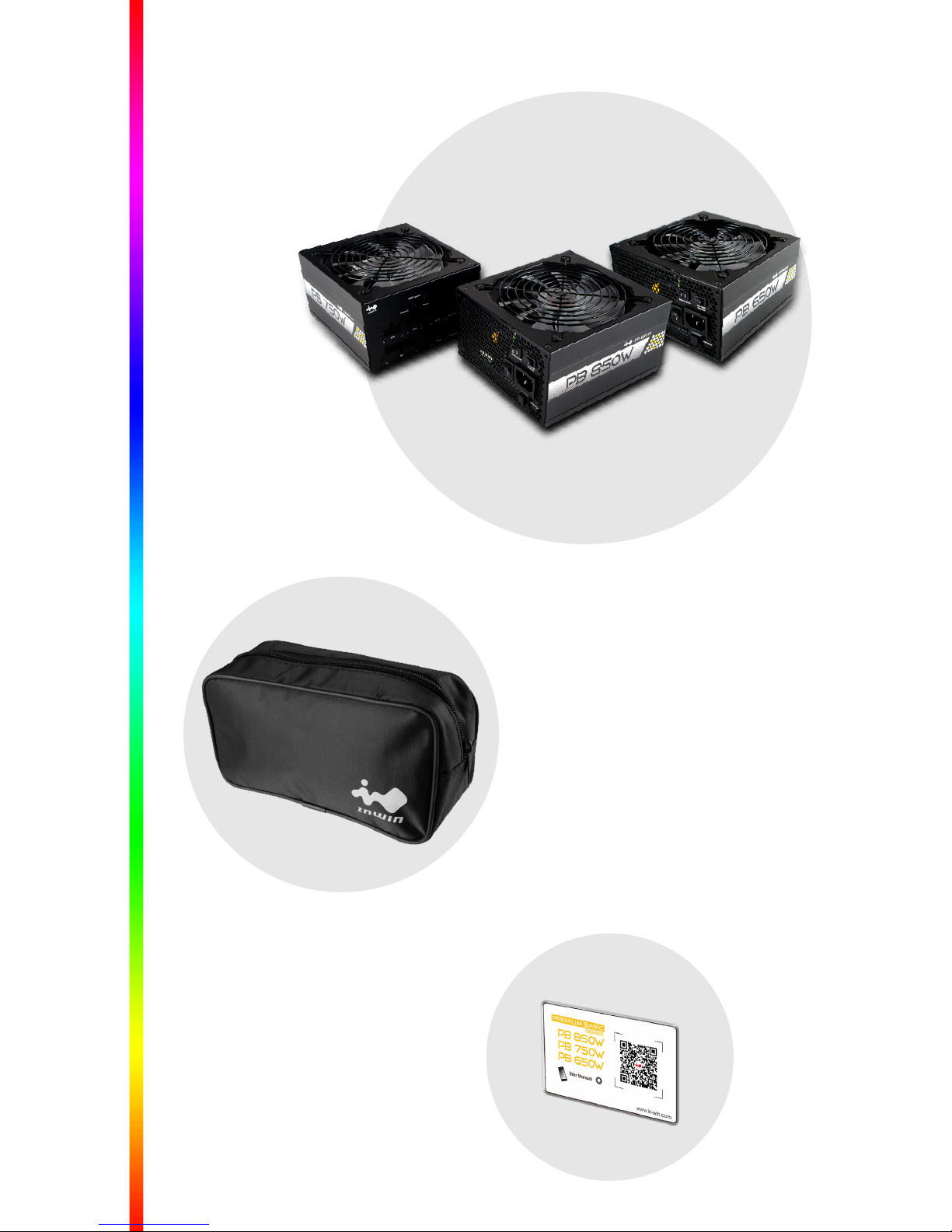
Package Contents
Package Contents
QR code card x1
Modularized Cables bag x1
- Power Cord x1
- Mounting Screws x4
- Cable Ties x8
PB Series Power Supply Unit x1
(PB-650W / PB-750W / PB-850W)
Page 5

Modularized Cables
Package Contents
X8
RGB LED Connector
Modular Cable
Cable tie
Power Cable
Screw
SATA (90 Degree)
Connector
Floppy
Connector
8 (6+2) Pin PCI-E
Connector
4 Pin Peripheral
Connector
20+4 Pin Motherboard
Connector
8 (4+4) Pin CPU
Connector
X1
X1
X1
X4
X1
X1X1
X3 X3
X1
PB-850WX3
PB-750WX2
PB-650WX2
PB-650W
PB-650W
PB-850W
PB-750W
PB-850W
PB-750W
Page 6

Cable Information
650mm
600mm
100mm
550mm
100mm100mm100mm
550mm
100mm100mm
550mm
100mm
150mm
570mm
8
0
m
m
Cable Information
650mm
100mm
650mm
8 (4+4) Pin CPU PB-650W
20+4 Pin Motherboard
8 (4+4) Pin CPU PB-750W PB-850W
SATA (90 Degree) PB-750W PB-850W
Floppy
8 (6+2) Pin PCI-E
4 Pin Peripheral
RGB LED Connector Modular Cable
SATA (90 Degree) PB-650W
Page 7

Installation
Installation
1. Make sure the power supply's AC power
cable is not connected before installation.
2. Place the power supply unit into the space
provided in the case and secure the power
supply unit with the screws.
3. Connect 24-pin power to the 24-pin socket
on the motherboard.
4. Connect the 8-pin + 12V cable to the
motherboard.
A.If your motherboard has an 8-pin + 12V
socket, connect the 8-pin cable directly
to your motherboard.
B.If your motherboard has a 4-pin socket,
detach the 4-pin from the 8-pin cable,
and plug the 4-pin cable directly to your
motherboard.
5. Connect the peripheral cables, PCI-Express
cables, and the SATA cables to the appropriate
socket.
6. Make sure all the cables are tightly connected
and save any unused modular cables for
future usage.
7. Connect the AC power cord to the power
supply and turn it on by switching the
power button to the "I" position.
Page 8

Troubleshooting
Switch Operation Instructions
1. Power Button
- O: Turns o the power
- l : Turns on the power
2. Silence Mode:
- ON: The uid dynamic bearing (FDB)
135mm fan will switch to hibernation
mode automatically once the system's
load is lower than 20%. This will maintain
the power supply's stability and noise
levels. The fan will begin to rotate when
the system's load is over 20% at a silent
18dBA output.
- OFF: Turn o the fan silence mode and
keep working.
3. M/B RGB Override:
- O: The PB Series is capable of syncing with
other RGB sync-ready components by
using the 4-pin RGB headers (such as
RGB fan and LED strip).
- l : Compatible with RGB-supported
motherboards (4-pin, 12V). Simply
activate the motherboard software and
the power supply's RGB LEDs will perfectly
complement your gaming rig.
Page 9

Installation
570mm
8
0
m
m
570mm
8
0
m
m
RGB Control
- PSU (out): Use the provided 4-pin (12V) header to connect
the PSU RGB Control port if your motherboard doesn't
support the RGB function or if you don't need to sync
RGB motherboard together. Please turn o the M/B
RGB override button (switch to "O" status).
- M/B(in): Use the provided 4-pin (12V) header to connect
the Motherboard RGB Control port to sync RGB omponents
together using the motherboard's software. Please turn
on the M/B RGB override button (switch to "I" status),
If you opt to use the Motherboard RGB Control port, the
PSU RGB Control port will be disabled.
4. RGB Mode: This mode provides eight options: Red,
green, dark blue, yellow, purple, light blue, white and
a breathing eect. Completely match the theme of
your rig! The power supply also features a built-in memory
function to save the applied color, insuring the same
selected color appears every time you boot your PC.
Please turn o the M/B RGB override button (switch to
"O" status) to manually switch the colors or activate
the breathing eect.
Compatible with other RGB sync-ready components. Please do not connect
with any motherboard or power in by SATA connector to avoid any damages.
Compatible with other RGB sync-ready components.
Page 10

Notices and Warranty
Troubleshooting
These troubleshooting points will help you
diagnose and solve problems with your power
supply if the unit fails to operate properly:
1. Please make sure the power supply and
power cord are connected properly.
2. Please make sure the power cord is
plugged into the power socket.
3. Please make sure the power supply I/O
button is switched to the "I" position.
4. Please check if all the connectors
(motherboard and peripheral) are connected
properly.
5. Please allow a 5-second interval before
turning the power on again when power
supply is switched o manually.
6. If you are still experiencing diculties,
please contact your local distributor for
RMA support.
Page 11

Installation
■
Notices
1. Please use the anti-static precautions while installing the
components to prevent damage and injury.
2. Install in accordance with the user manual's instructions
and safety warnings.
3. High voltages are present in the power supply. Do not open
the power supply case. Any modications may damage
the product and may place the user at risk.
4. Do not use the power supply if it has been wet or damaged
to avoid electric shock or injury.
5. Do not install the power supply near any heat sources such as:
radiators, heat registers, or other apparatus that produces heat.
6. Do not insert any objects into the open ventilation or fan
grill area.
7. Use only InWin supplied cables. Other cables might not
be compatible and could cause serious damage to your
system and power supply.
8. Do not modify the cables and/or connectors included with
the power supply.
■
Warranty
1. InWin provides a 5-year warranty toward the product. The
warranty covers malfunctions or aws before customer
use. The warranty starts from your initial purchase (according
to the date on your receipt). Please note that we do not
honor the warranty for the product if it is not purchased
personally or if it is purchased through an unauthorized
distribution channel.
2. This limited warranty shall not apply if the defect was caused
through any of the following:
1) Abuse and misuse, 2) Operation outside of product
specication, 3) Unauthorized service or modication, 4)
Any and all alteration of the product.
3. For more detailed warranty information, please visit the
InWin retail website at www.in-win.com.
4. The actual product is subject to change without prior
notice. In Win Development Inc. reserves the right to
make nal modications.
Notices and Warranty
Page 12

Copyright © 2018 In Win Development Inc. All Rights Reserved.
 Loading...