

Page 1
IW-RS316-03
User’s Manual
Page 2

- 1 -
Table of Content
PREFACE
P.3
SAFETY INFORMATION
P.3
SPECIFICATIONS
P.5
1 Product Introduction
1.1 Box Content P.6
1.2 General Information P.7
1.2.1 Front Panel Controls and Indicators P.8
1.2.2 Rear Panel Configuration P.9
2 Hardware Installation
2.1 Removing and Installing a Hard Drive P.10
2.1.1 Installing a Hard Drive P.10
2.1.2 Removing a Hard Drive P.10
2.2 Removing and Installing Top Cover P.11
2.3 Removing and Installing a Fan Module P.12
2.3.1 Removing a Fan Module P.12
2.3.2 Installing a Fan Module P.12
2.4 Removing and Installing a PSU Module P.13
2.4.1 Removing a PSU Module P.13
2.4.2 Installing a PSU Module P.14
2.5 Installing Slide Rail P.14
2.5.1 Identifying the slide Rail P.14
2.5.2 Take out the inner rail and slide the intermediate rail back P.14
2.5.3 Attach the inner rail to the chassis P.15
2.5.4 Mount the rail bracket to the cabinet P.15
2.5.5 Insert the chassis to the cabinet P.16
2.6 Installing Motherboard P.17
2.7 Connecting Cable P.18
3 Backplane Introduction
P.19
4 Expander Board Introduction
P.20
4.1 Key Features P.21
4.2 UART Usage P.22
4.2.1 UART configuration P.22
4.2.2 System Revision P.23
4.2.3 System Monitoring P.24
Page 3

- 2 -
4.2.4 Disk PHY Status P.25
4.2.5 Firmware Update P.26
4.2.5.1 SAS Expander Operation Firmware Update P.26
4.2.5.2 SAS Expander MFG CFG Binary Update P.28
5 Compatibility Lists
P.29
6 Q&A
P.29
7 Technical Support
P.32
Page 4

- 3 -
Page 5

- 4 -
PREFACE
Thank you for choosing In Win IW-RS316-03. This manual is written for system technicians who are
responsible for installation, troubleshooting, managing, and repairing this server chassis. This
document provides the overview of all the features of the chassis, a list of accessories or other
components you may need to finish the installation, troubleshooting methods, and instructions of
adding and removing components on the In Win IW-RS316-03. For the latest version of this manual,
you may visit In Win’s server website to download the latest updated version.
SAFETY INFORMATION
To ensure safe and smooth operation of your In Win IW-RS316-03, it is essential that you choose an
appropriate location for the system, provide an appropriate operating environment, and adequate
power for all components of the system. As you plan for installation, follow the guidelines below to
ensure that the system and its environment are safely and appropriately positioned for efficient
operation and service. Your system should be installed and serviced only by technically qualified
persons.
Environment selection: The system is designed to operate in a typical office environment. The location
should be a clean, dry, and free of airborne particles; a well-ventilated room and away from sources of
heat including direct sunlight and radiators; it should keep the sources of vibration or physical shock
away; the space should be with a properly grounded wall outlet, and with sufficient space to access the
power supply cords. The operation environment temperature should be around 0°C to 40°C (32°F to
104°F).
Heed safety instructions: Before working with In Win IPC/Storage server/ System products, we strongly
recommend you are using this guide as a reference and follow the safety instructions. The instructions
in this manual will help you ensure and maintain compliance with existing product certifications and
approvals. Follow the described, regulated components mentioned in this manual. Use of non UL
listing products or other regulatory did not approvals will make non-compliance with product
regulations in the region(s) in which the product is sold.
System power on/off: The power button DOES NOT totally turn off the system AC power. To remove
the power of system, you have to unplug the AC power cord from the outlet or system’s power supply
units. Make sure the power cord is unplugged before you open the chassis, add, or remove any
components.
Page 6
- 5 -
Hazardous conditions, devices and cables: Hazardous electrical conditions usually present on power
supply units, and communication cables. Disconnect the power cord, and any other device which
attached to the server before opening the case. Otherwise, it will raise the risk of personal injury or
equipment damage.
Electrostatic discharge (ESD) and ESD protection: In most cases, ESD damages disk drives, electronic
boards, and other parts. We recommend that you work the installation only at an ESD free space. If the
situation does not allow, perform ESD protection actions by wearing an anti-static wrist strap attached
to ground any unpainted metal surface on your server during your operation.
Installing or removing jumpers: A jumper is a short length of conductor used to close, open or bypass
part of an electronic circuit. Jumpers on In Win backplane have a small tab on top that you can pick up
with your fingertips. Grip the jumper carefully, and plug the jumper to cover the jumper pins on the
backplane. Once you need to remove the jumper, gripping the jumper, and carefully pull out without
squeezing.
CAUTION
To avoid damage and prove your safety, please notice and following the terms listed below:
1. No to populate hard drives and turn on the power before the system is settle down.
2. Tighten or loosen all the screws, please use screw driver to operate.
3. Apply the correct screws which packed in the accessories box.
4. For your safety, it requires at least two persons lift, and place the unit.
5. Before mounting the unit to the cabinet, make sure the rail is installed correctly.
6. When installing and removing any module or parts, please operate by the handles.
Page 7

- 6 -
SPECIFICATIONS
Model Name IW-RS316-03
Standard EIA-RS310D
M/B Form Factor ATX (12” x 9.6”); ATX(12” x10”); EEB(12” x 13”)
Dimensions (D x W x H) 660.4 x 482.6 x 131 mm (26" x 19" x 5.25")
Drive Bay
External: Hot Swap 3.5” x 16
Internal: 2.5” HDD x 2
or Rear 2.5" Hot-Swap for OS (SSD 7mm) x 2 (Optional)
Power Supply
Supports
▪ Form Factor: Platinum CRPS Redundant
▪ Watt: 800W
Indicator Power LED, LAN1/LAN2/LAN3/LAN4 LED, System LED, ID LED
Front Control Panel Power on/off, Reset, NMI, ID SW, USB3.0 x1, Mute button
Backplane MINI SAS HD /12Gb/s with expander
Cooling Fan
Supports 8038mm PWM Fan x3; another 8038mm Fan for PCI-e, (Optional)
Modularize design with anti-vibration
Expansion Slot Full height PCI Slot x 7
SAS 12G Expander
support
LSI Expander support
Material
Material: SGCC
Thickness: 1.0 mm
Slide Rail 20" & 28" King slide Rail for 438 chassis, Ball-bearing, Support Screw less
Page 8
- 7 -
1 Product Introduction
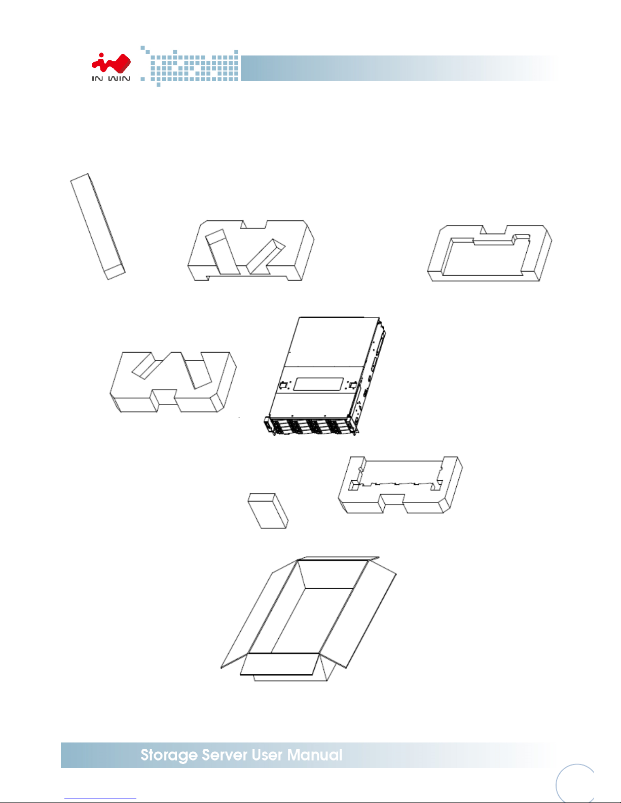
1.1 Box Content
Page 9
- 8 -
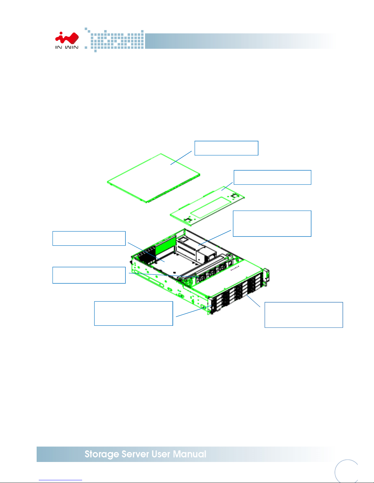
1.2 General Information
When you open the chassis should be like the diagram shows.
Rear top cover
CRPS Redundant or Single
module power supply
Middle top cover
16 x 3.5” tool-less HDD
slots
Max. PWM Fan (3pcs)
ATX or EEB M/B
Front Controls and
indicators
Page 10
- 9 -
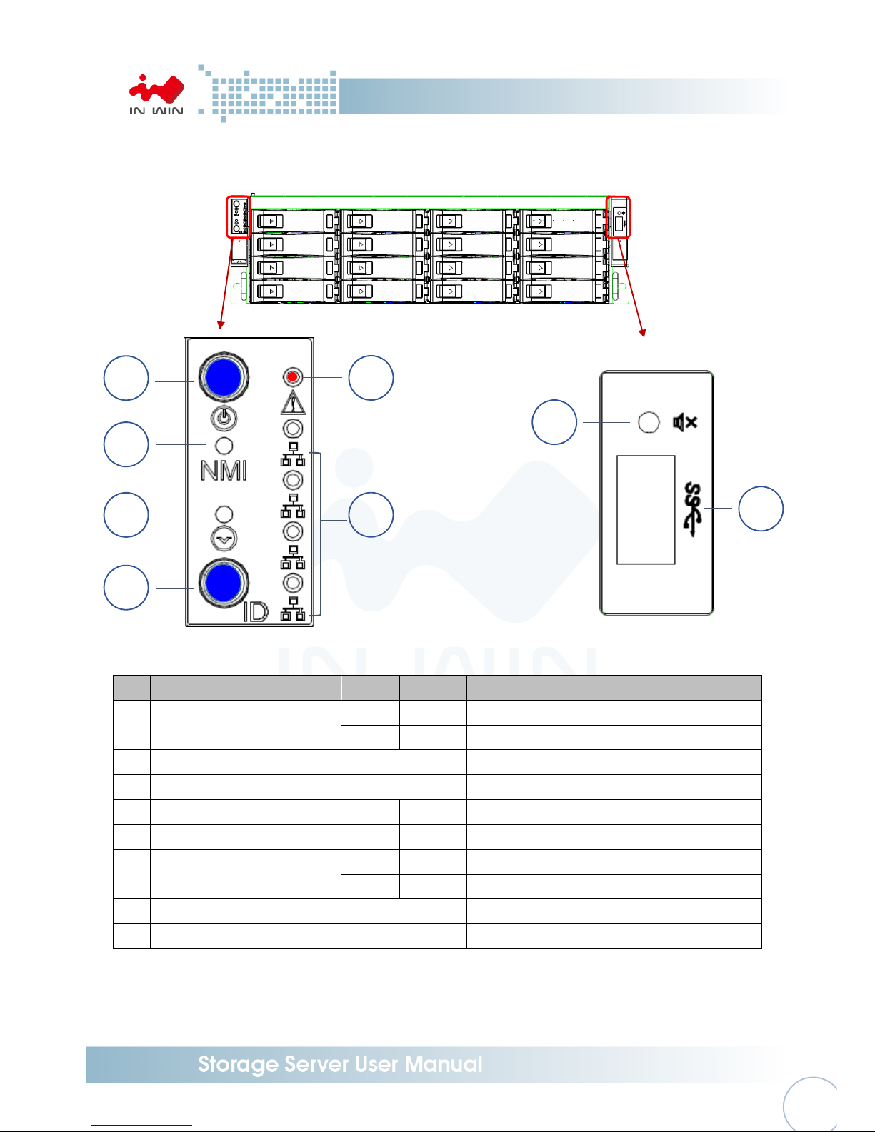
1.2.1 Front Panel Controls and Indicators
No.
Name Color Status Description
1 Power ON/OFF Button with LED
Blue Solid on System is powered on
N/A Off System is not powered on
2 NMI Button N/A Press the button to activate user define
3 System Reset Button N/A Press the button to activate system reset
4 Chassis ID Button with LED Blue Solid on Press the button to activate system identification
5 System Fail LED Red Solid on System Fault (Beeper)
6
LAN LED (From top to bottom
ranked LAN1 - LAN4)
Amber
Blink Link between system and network
N/A Off No date transmission or receiving is occurring
7 Mute Button N/A Press the button to activate beeper mute
8 USB3 Connector N/A USB devices connection
1
2
3
4
5
6
7
8
Page 11

- 10
-
1.2.2 Rear Panel Configuration
No.
Name Description
1 Power Module 1 Default primary power supply module
2 Power Module 2 Backup power supply module
3
System I/O (depend on
M/B specification)
The I/O shield should come with motherboard or provided by motherboard
vendors
4 7 Full Height PCI E Slot
The slot support 120mm high profile cards. The bracket should be removed
before using.
5 OS HDD
This slot is for In Win OS disk backup module (option), which support two
2.5” 7mm SSD and hot swap function.
6 Phone Jack for RS232
1
2
3 4
5
6
Page 12

- 11
-
2 Hardware Installation
2.1 Removing and Installing a Hard Drive
In Win IW-RS316-03 is featured tray-less disk population, users do not need to use screw to
mount disks, and be able to perform quick hard disks replacement.
2.1.1 Installing a Hard Drive
Step 1: Press the release button then pull outward the handle
Step 2: Insert the hard drive to the slot
Step 3: Push back the lever until it clicks
Step 1 Step 2
Step 3
2.1.2 Removing a Hard Drive
Step 1: Press the release button then pull outward the handle
Step 2: Pull out the hard drive
Step 1
Press
Pull
Insert the HDD
Page 13

- 12
-
Step 2
2.2 Removing and placing Top Cover
Step 1: Press inward the button then lift the middle top cover up
Step 2: Loosen the screws of the rear top cover on the both sides, pull back the cover and lift to
remove.
Step 3: To place the cover, mount the rear cover and push it to the fitted location. Screw up to fix
the rear cover.
Step 4: Put down the middle cover and make sure the clip clicks.
Step 1 Step 2
Step 3
Pull
Press
Pull
Page 14

- 13
-
2.3 Removing and Installing a Fan Module
2.3.1 Removing a Fan Module
Step 1: Release the thumb screw then remove the fan bar
Step 2: Unplug the fans’ power cable from the motherboard if necessary
Step 3: Hold and lift the fan module from the chassis
Step 1
Step 2 Step 3
2.3.2 Installing a Fan Module
Step 1: Hold and put the fan into the fan slot
Step 2: Stake on the fan bar to fix the fan module
Step 3: Tight up thumb screw
Step 1 Step 2
Page 15

- 14
-
Step 3
2.4 Removing and Installing a PSU Module
In Win IW-RS316-03 built-in a redundant power supply module. With this function, system is
capable to keep working whether as one power supply unit is failure. To replace it, user only
need to release the failure one then insert a good one.
2.4.1 Removing a PSU Module
Step 1: Press the release tab on the back of power supply unit
Step 2: Pull the power supply unit out using the handle
Step 1
Step 2
Press
Pull
Page 16

- 15
-
2.4.2 Installing a PSU Module
Step 1: Make sure the label faces up, and push the power supply module into the cage until
you hear a click.
NOTE : 1. The unit supports In Win PSU module only, please do not insert other brands of PSU.
2. The two PSU modules’ output wattage must be the same.
Step 1
2.5 Installing Slide Rail
In Win IW-RS316-03 is a rackmount model, which support EIA-RS310D standard cabinet and
chassis rack. In Win provides standard slide rail to let users mount the chassis on to the cabinet.
2.5.1 Identifying the slide Rail
The slide rail by your order might be different. You can reference the quick installation guide
inside the slide rail package and follow the instruction to mount the rail on to your cabinet or
chassis rack.
2.5.2 Take out the inner rail and slide the intermediate rail back
Step 1: Pull out the inner rail until it hits the terminal, then pull the blue release tab to
unlock.
Step 2: Continue pulling the inner rail to the second stop, pull the white tab to release the
inner rail.
Step 3: Pull the latch on the medium rail and push back the medium rail back.
Insert
Press
Label
Page 17

- 16
-
2.5.3 Attach the inner rail to the chassis
Step 1: Install the inner rail onto the chassis. Make sure the key holes and the standoff are
well locked which you will hear a click.
Step 2: Repeat the same action to the other side.
Step 3: When removing the inner rail, pulling the latch upward and release the keyhole from
standoff to detach the inner rail. (Action and in the figure)
2.5.4 Mount the rail bracket to the cabinet
Step 1: Extend the bracket over the rear rack of the cabinet.
Step 2: Pull back to and push bracket’s standoff into the screw holes on the rack, if your
action is correct, you will hear a click.
Step 3: Extend the opposite side of bracket to the front rack of the cabinet.
Step 4: Pull the bracket to let the standoff over the screw holes on the front rack until you
hear a click.
Step 5: The other side of rail is symmetrical, repeat the installation Step 1-4.
Step 6: Once you would like to detach the bracket, pull the release tab on the rear bracket
and Pull the latch on the front bracket to release the bracket. Repeat the same action
to the other side.
Step 1 Step 2
Step 3
Step 1 Step 2
Step 3
Page 18

- 17
-
2.5.5 Insert the chassis to the cabinet
Step 1: Pull out the medium rail to the stop position.
Step 2: Let the ball bearing retainer is at e front end of the middle rail, you will hear a click if
the action is correct.
Step 3: Insert the inner rail on the both side of chassis, into the middle rail.
Step 4: Push the chassis to the terminal position, then pull the blue release tab to continue.
Step 5: When reaching the second stop position, pull the blue release tab again to continue.
Step 6: Pull the chassis into rack completely, and make sure the front end of the chassis align
with the edge of the rack to complete the installation.
Page 19

- 18
-
SAS connectors
2.6 Installing motherboard
Before installing the motherboard, please find the IO shield form your motherboard package, and
install it to the system IO window 1.2.2 shows. If you cannot find the IO shield, please check with
your motherboard vendor, or contact In Win for IO shield OEM service.
Step 1: Measure the motherboard location and removing the plastic dots to appear the holes.
Step 2: Install the steel pillars, which you can find in the accessories box to the holes matching
the motherboard’s mounting holes, you may use a flathead screw driver.
Step 3: Place the motherboard down to the chassis, and make sure the pillars’ threaded holes are
matching the mounting holes on the motherboard.
Step 4: Use hex screws from the accessories box to fix the motherboard in the chassis.
2.7 Connection Cable
2.7.1 Connecting expander through SAS connectors
In Win IW-RS316-03 needs SAS 8643 cable to connect the expander to your motherboard. By
the difference of spec, you will need different type of cable. You can purchase the cable from
In Win, or source any SAS 8643 cable which meets STA standard by yourselves.
Port 2 and 3 are for connecting to motherboard or RAID controller; port 1 is for cascade.
1 2 3
Page 20

- 19
-
2.7.2 Connecting LED, front control panel and front USB IO ports
As 1.2.1 descripts, In Win IW-RS316-03 built-in a set of front control panel and USB access
ports. You need to cover the connectors to the pins on the motherboard to active the
functions. The pin function and location you can find from your motherboard’s user guide.
Connector Name Abbreviation Color Front IO Indication
Power Switch PWR SW Brown Power ON/OFF Button with LED
Power LED PWR LED Purple Power ON/OFF Button with LED
NMI Switch NMI SW Yellow NMI Button
Reset Switch RST SW Orange System Reset Button
ID Switch ID SW Blue Chassis ID Button with LED
ID LED ID LED Green Chassis ID Button with LED
Alarm LED ALM LED Red System Fail LED
LAN 1 LED LAN1 LED Gray LAN LED
LAN 2 LED LAN2 LED Gray LAN LED
LAN 3 LED LAN3 LED Gray LAN LED
LAN 4 LED LAN4 LED Gray LAN LED
USB 3.0 Connector None Black Flat USB 3.0
Mute Switch Mute White Mute Switch
USB 3.0
LED Connector
Page 21

- 20
-
3 Backplane Introduction
Location Description
CN01-CN16 SAS Receptacle Connector (SAS 12Gb/s 3.5”HDD Connector)
Dxx1 HDD Power LED
Dxx2 HDD Access/Fault LED
CEN1 Primary SAS Expander Slot
CEN2 Secondary SAS Expander Slot
JD1-JD3 MCU Programming(Factory only)
FPC1 Front Switch FPC/IO Board Connector
FPC2 Front Switch FPC/IO Board Connector(Factory only)
PW1 ATX 2x7P 5V Power Connector
PW2 ATX 2x8P12VPower Connector
JT1 HW LED Test(Factory only)
JT2 HW Test(Factory only)
J1 Server Mute SW Connector
JM1 Server/JBOD Select
JM2 HDD LED Behavior Select
JC1 PDB Control Connector
JC2 PMBUS(Factory only)
Page 22

- 21
-
4 Expander Board Introduction
Location Description
GF1 BP Golden Finger Connector
GF2 IO Board Golden Finger Connector
EFN1 Expander FAN Connector
JM1
Single/Dual Power Module Select:
Single: Jumper 1-2; Dual: Jumper 2-3
JD1 ICE Debug Port
JD2 Smart Console
JD3 Debug Port
Page 23

- 22
-
4.1 Key features
Reliable High Data Rate support (up to 12Gbps)
SAS 12Gbps support and SATA3 6Gbps support to provide a reliable high
performance data rate.
HDDs hot-swap-able
HDD is hot-swap-able. No need to shutdown system for HDD installation and/or
replacement while there is HDD failure happens or intend to add new HDD to the
system.
Cascading
There is a cascading port on Expander for cascading to another Expander for
expanding disk space.
Page 24

- 23
-
4.2 UART Usage
4.2.1 UART configuration
RS-232 UART port on Expander module provides a serial connection for users to manage
with terminal application such as Tera Term, Hyper Term…etc.
To manage Expander through UART port, the settings below have to be properly configured
to make it work.
Baud Rate : 115200
Data : 8 bit
Parity : None
Stop Bit : 1 bit
Flow Control : None
When connected, there is a prompt display on terminal then users can start typing CLI
commands
Page 25

- 24
-
4.2.2 System Revision
To check the Expander revision, typing “rev” and “sys rev” to get the expander information
such as Vendor ID, Firmware Version, SAS Address, …etc.
Page 26

- 25
-
4.2.3 System Monitoring
To monitor the enclosure sensor status such as temperature and DC power amplitude by
command “sys” in the UART
Page 27

- 26
-
4.2.4 Disk PHY Status
To monitor the SAS PHY status, typing “Phyinfo” or “sys hdd” to check. Users can check the
disk link status by using these commands.
Page 28

- 27
-
4.2.5 Firmware Update
In some occasions, when required, users can update expander firmware through UART port
via Xmodem protocol.
* Firmware upgrade is risky and is not recommended to conduct by users unless there is
technical support people onsite.
There are 2 firmware for expander. Be sure these binary files are available in the host before
conducting firmware update.
1. SAS Expander Operation Firmware
2. SAS Expander MFG CFG binary
The updated firmware does not take effect until a reset (either system reboot or reset
expander via CLI command – “reset”).
4.2.5.1 SAS Expander Operation Firmware Update
A. “fwdl” command on terminal
B. Type “y” to commit firmware upgrade.
C. Select xmodem as the protocol to transfer file.
Page 29

- 28
-
D. Select the correct SAS Expander firmware file.
E. Click on “Open” to start the selected firmware transferring to SAS Expander.
F. Terminal would then start firmware transfer.
Page 30

- 29
-
G. After firmware transfer completed, typing ‘reset’ command in terminal or power
cycling system to activate new firmware.
4.2.5.2 SAS Expander MFG CFG Binary Update
A. Similar to operation firmware upgrade, typing “mfgdl” on console.
B. Type “y” to commit MFG file upgrade.
C. Select xmodem as the file transfer protocol.
D. Select the correct MFG CFG file from file browser.
E. Click “Open” to start file transfer.
F. Terminal would then start file transfer.
G. After firmware transfer completed, typing ‘reset’ command in terminal or power
cycling system to activate new firmware.
Page 31

- 30
-
5 Compatibility Lists
To reach best performance and avoid system failure, In Win strongly recommend users choosing the
components from In Win’s compatibility list. All the components are tested in In Win’s lab and assured
the components are working well with In Win’s chassis.
You can download the latest updated device compatibility list from In Win’s website:
https://www.in-win.com/en/ipc-server
6 Q&A
Section 1: Expander
1. What is the In Win Expander’s function?
A: The expansion the capacity, the expander can manage more SAS drives via one SAS cable in
the JBOD.
2. Why IW-RS series storage server chassis are built-in expander board, and IW-RJ series JBOD
enclosures uses expander module?
A: IW-RS chassis needs a motherboard to compose a system, the expander board can work
seamlessly with motherboard to manager the drives. Different from the chassis, IW-RJ JBOD
enclosure use hot swap expander modules to satisfy the requirement of both capacity
expansion and JBOD redundancy.
3. Why IW-RJ JBOD enclosure needs 2 expander modules?
A: It is for redundancy. If user does not need this function, single expander module also works
out.
4. What are the functions of the three connector ports on the expander module?
A: SAS 0 is the connecting port to Server 0/ RAID or HBA 0, SAS 1/ RAID or HBA 1 is to Server 1;
EXP is the port to cascade another JBOD to expand the capacity.
5. Can I add more ports to the expander module?
A: First of all, we have to understand that the ports are for cable connecting. Second, as only as
the Phy quantity of the expander chip set allows, technically, this configuration works out. Yet,
we also need to consider about the technical alignment. For example, an expander with a 3x36R
chipset has totally 36 Phy, and each ports consumes 4 Phy; thus, we can design a 9-port
expander (36/4 = 9) to connect 9 cable. However, once we use out all the Phy for connecting, we
have no remaining Phy to connect HDD, this design will goes meaningless.
Page 32

- 31
-
6. Once I find the expander is failure, what can I do?
A: IW-RS series: Power off the system, and make sure the system is totally shut down. Unplug
the SAS cable to replace the expander board.
IW-RJ series: Remove the failure expander module, and replace a new expander module.
Section 2: Hard Disk
7. What is the different between SAS and SATA disk, and how to choose?
A: SATA has only one throughput channel for data transmission, SAS has two. Once the system is
designed with redundant function, SAS disk provides performance and reliability. SATA provide a
choice of cost selective option.
8. Are SAS and SATA disks are compatible with both In Win IW-RS series and IW-RJ series?
A: Yes, In Win IW-RS and IW-RJ support both SAS and SATA disks.
9. Can I populate 2.5” disks to the 3.5” tray-less slots?
A: 3.5” tray-less slot does not support 2.5” disks at this moment, if this requirement is
mandatory, please contact In Win sales for OEM service.
10. Is the storage server or JBOD must be full populated to work?
A: No, you can populate partial bays and start the system. Once you need more storage space in
the future, then add more disks.
11. Can I populate both SAS and SATA disks in an enclosure?
A: Yes, it works. However, you may need to consider about the alignment issue.
12. If my system drive is failure, can I replace the drive without shutting down the system?
A: In default, IW-RS series’ two internal disks doesn’t support hot-swap feature. You can order
an optional 2bay hot-swap system disk module to reach your purpose.
Section 3: RAID/ Cascade
13. Is RAID card a requirement component for composing a RAID system?
A: If your motherboard featured on-board RAID function, or your OS support software RAID, you
do not need a RAID card. For technical details, please contact your motherboard or software
vendor.
14. How many units can IW-RJ series JBOD cascade?
A: In maximum, a daisy chain can stripe 48 disks.
Page 33

- 32
-
15. If I would like to cascade the JBOD, what components do I need?
A: You will need a SFF-8644 to SFF-8644 SAS cable, which meets T10 standard. And the length
we suggest less than 3M to reach the best performance.
16. If I only have an internal RAID controller card, and I would like to expand the capacity, how to
add more disks?
A: IW-RJ series JBOD is for this purpose. If your RAID controller card does not have external
connecting port, you can use a SFF-8643 to SFF-8644 adaptor cable to connect the JBOB
enclosure.
Section 4: Others
17. Why PSU has two modules? What are these two modules for?
A: Two PSU modules are for redundancy, if you need this function, PSU with two modules is
required.
18. Can I add or reduce the quantity of fans?
A: The quantity of fan is related to the radiating efficiency. Usually, the quantity of fans depends
on the system loading and the heat generation. Unless you have tested, or we strong
recommend not to change the default fans quantity.
19. Which parts support hot-swap feature.
A: IW-RS storage server: Fans, PSU, HDD
IW-RJ JBOD enclosure: Fans, PSU, Expander Modules, HDD
20. Can 12Gb SAS ports compatible with 6Gb SAS or 6Gb SATA ports? Any adaptor can convert?
A: 12Gb SAS does not align with 6Gb SAS, so In Win does not have adaptor for this case.
21. If the arm or handle is broken, how can I fix or replace it?
A: Please contact your local In Win partner, or support contact for replacing and repair service.
22. If I would like to modify the GUI, how can I access.
A: The copyright of the GUI is belonging to In Win. If you would like to amend anything of the
GUI, please contact In Win sales for ODM service.
Page 34

- 33
-
7 Technical Support
If you need help on installation or troubleshooting, you can contact your local In Win partner, or send
email to In Win’s local contact for technical assistance.
 Loading...