

Page 1

IW-RN224-03
User Manual
Page 2
Table of Contents
PREFACE ....................................................................................................................................... 1
SAFETY INFORMATION ................................................................................................................. 1
CAUTION ...................................................................................................................................... 2
SPECIFICATIONS ............................................................................................................................ 3
1 Product Introduction ............................................................................................................. 4
1.1 Box Contents ............................................................................................................................ 4
1.2 General Information ................................................................................................................. 5
1.2.1 Front Panel Controls and Indicators .......................................................................................................... 6
1.2.2 Rear Panel Configuration ........................................................................................................................... 7
2 Hardware Installation ........................................................................................................... 8
2.1 Removing and Installing a Hard Drive ........................................................................................ 8
2.1.1 Installing a Hard Drive ................................................................................................................................ 8
2.1.2 Removing a Hard Drive .............................................................................................................................. 9
2.2 Removing and Placing the M/B Node ........................................................................................ 9
2.3 Removing and Installing the Fan Module................................................................................. 10
2.3.1 Removing the Fan Module ....................................................................................................................... 10
2.3.2 Installing the Fan Module ........................................................................................................................ 10
2.4 Removing and Installing the PSU Module ................................................................................ 11
2.4.1 Removing the PSU Module ...................................................................................................................... 11
2.4.2 Installing the PSU Module ........................................................................................................................ 11
2.5 Installing the Motherboard ..................................................................................................... 12
2.6 Connecting Cables .................................................................................................................. 12
2.6.1 Connecting Expander Through SAS Connectors ...................................................................................... 12
2.6.2 Connecting LEDs, Front Control Panel and Front USB ............................................................................. 13
2.7 Installing the Slide Rail ............................................................................................................ 14
2.7.1 Identifying the Slide Rail .......................................................................................................................... 14
2.7.2 Removing the Inner Rail and Sliding the Intermediate Rail Back ........................................................... 14
2.7.3 Attaching the Inner Rail to the Chassis .................................................................................................... 14
2.7.4 Attaching the Inner Rail to the Chassis .................................................................................................... 15
2.7.5 Inserting the Chassis to the Cabinet ........................................................................................................ 16
3 Backplane Introduction ....................................................................................................... 17
Page 3

4 Expander Board Introduction .............................................................................................. 18
4.1 Key Features ........................................................................................................................... 18
4.2 UART Usage ............................................................................................................................ 19
4.2.1 UART configuration .................................................................................................................................. 19
4.2.2 System Revision ........................................................................................................................................ 20
4.2.3 System Monitoring ................................................................................................................................... 21
4.2.4 Disk PHY Status ......................................................................................................................................... 22
4.2.5 Firmware Update ...................................................................................................................................... 23
5 Compatibility Lists .............................................................................................................. 26
6 Q&A .................................................................................................................................... 26
7 Technical Support ................................................................................................................ 27
Page 4
1
PREFACE
Thank you for choosing the InWin IW-RN224-03. This manual is written for system technicians who
are responsible for installation, troubleshooting, managing and repairing this server chassis. This
document provides the overview of all the features of the chassis, a list of accessories or other
components you may need to finish the installation, troubleshooting methods and instructions on
adding and removing components on the InWin IW-RN224-03. For the latest version of this
manual, you may visit InWin’s server website to download the latest updated version.
SAFETY INFORMATION
To ensure a safe and smooth operation of your InWin IW-RN224-03, it is essential that you choose
an appropriate location for the system, provide an appropriate operating environment and supply
an adequate amount of power for all components of the system. As you plan for installation, follow
the guidelines below to ensure that the system and its environment are safely and appropriately
positioned for efficient operation and service. Your system should be installed and serviced only by
a qualified technician.
Environment selection: The system is designed to operate in a typical office environment:
• The location should be clean, dry and free of airborne particles.
• It should be situated in a well-ventilated room, and away from sources of heat including direct
sunlight and radiators.
• It should be kept away from sources of vibration or physical shock.
• The space should be accommodated with a properly grounded wall outlet, and with sufficient
space to access the power supply cords.
• The operating environment temperature should be around 0°C to 40°C (32°F to 104°F).
Heed safety instructions: Before working with InWin’s server/storage products, we strongly
recommend you use this guide as a reference and follow the safety instructions. The instructions in
this manual will help you ensure and maintain compliance with existing product certifications and
approvals. Follow the described, regulated components mentioned in this manual. Use of non-UL
listed products, or products from alternative regulators, may not comply with product regulations
in the region(s) in which this product is sold.
System power on/off: The power button DOES NOT totally turn off the system AC power. To
remove the system’s power, you must unplug the AC power cord from the outlet or the system’s
power supply units. Make sure the power cord is unplugged before you open the chassis to
add/remove any components.
Hazardous conditions, devices and cables: Hazardous electrical conditions can be present on/in
power supply units and their cables. Disconnect the power cord and any other device attached to
the server before opening the case. Failure to follow safety procedures will increase the risk of
personal injury or equipment damage.
Page 5
2
Electrostatic discharge (ESD) and ESD protection: In most cases, ESD may damage disk drives,
electronic boards and other parts. We recommend that you conduct installation only at an ESD
free space. If not possible, perform ESD protection protocol by wearing an anti-static wrist/ankle
straps attached to the ground on any unpainted metal surface on your server during operation.
Installing or removing jumpers: A jumper is a short length conductor used to close, open or bypass
part of an electronic circuit. Jumpers on InWin backplanes have a small tab on top that you can
pick up with your fingertips. Grip the jumper carefully, and plug the jumper to cover the jumper
pins on the backplane. Once you need to remove the jumper, grip the jumper and carefully pull
without squeezing.
CAUTION
To avoid damage and maintain your safety, please read the following terms listed below:
1. Do not populate hard drives and turn on the power until the system has
secured.
Make sure hard drives and other components are properly connected before
turning on the system.
2. Tighten or loosen all screws with a screwdriver.
3. Apply the correct screws included within the accessory box.
4. For your safety, please have at least two people lift and place the unit in its
designated area.
5. Before mounting the unit to the cabinet, make sure the rail is installed correctly.
6. When installing and removing any module or part, please use the provided
handles.
Page 6
3
SPECIFICATIONS
Model Name
IW-RN224-03
Standard
EIA-RS310D
M/B Form Factor
ATX (12" x 9.6"), ATX (12" x 10"), EEB (12" x 13")
Dimensions (D x W x H)
w/o Front Door
660.4 x 482.6 x 87 mm (26" x 19" x 3.5")
Drive Bay
External: Hot-swap 2.5" x 24
Internal: 2.5" HDD (7mm thickness) x 2 for each node
Power Supply
Supports
▪ Form Factor: Platinum CRPS redundant with PDB cable
management
▪ Watt: 1200W
Front Control Panel/
per Node
Button: Power On/Off, NMI, Reset, ID SW
Indicator: Power LED, ID LED, System LED, LAN1/LAN2/LAN3/LAN4
LED
Cooling Fan/
per Node
▪ 4028mm PWM fan x 5
▪ Modular design with anti-vibration
Expansion Slot/
per Node
▪ Low-profile PCI slot x 1
▪ Full height PCI slot x1
Backplane
Mini SAS HD / 12Gb/s with expander
SAS 12G Expander /
per Node
Supports LSI 3 x 36R expander
Material
Material: SGCC
Thickness: 1.0 mm
Rail Kit
Supports 20" or 28" tool-less & ball-bearing slide rail
* The actual product is subject to change without prior notice. In Win Development Inc. reserves the
right to make any final modifications.
Page 7
4
1 Product Introduction
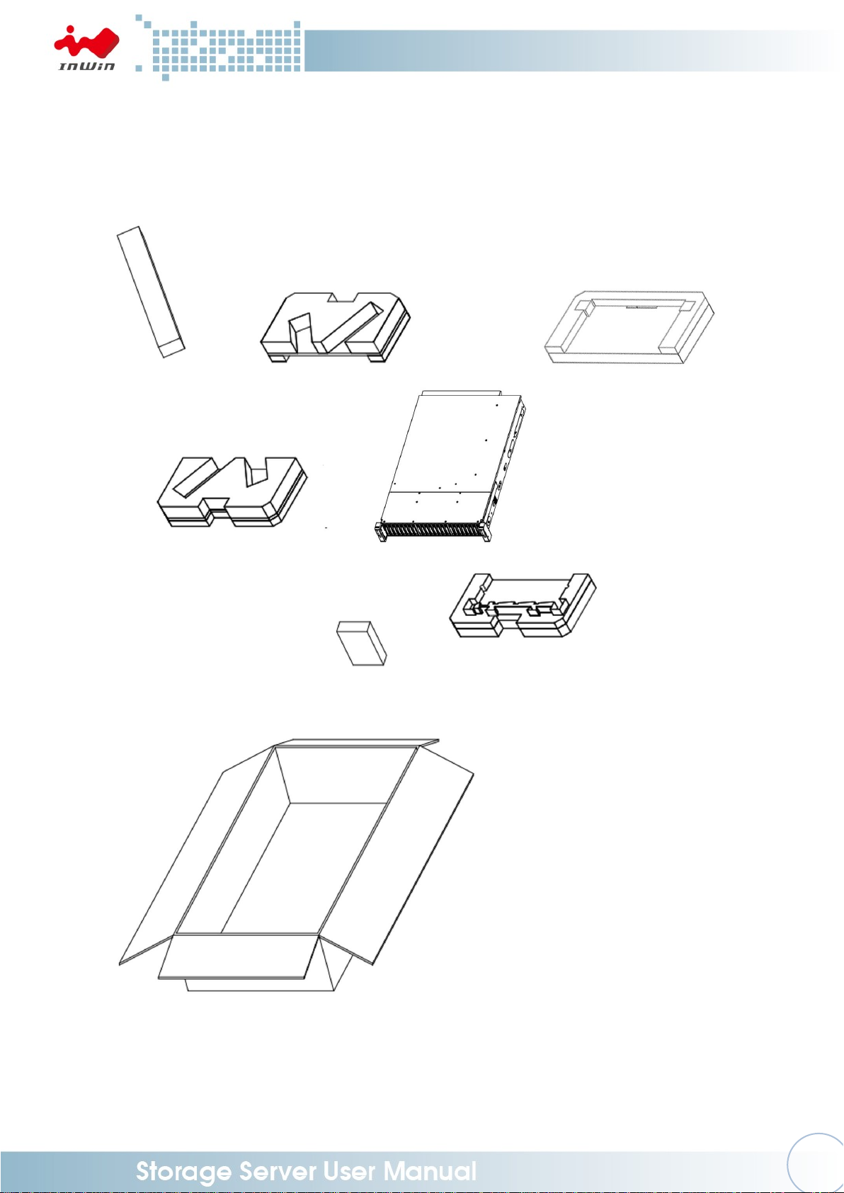
1.1 Box Contents
Page 8
5
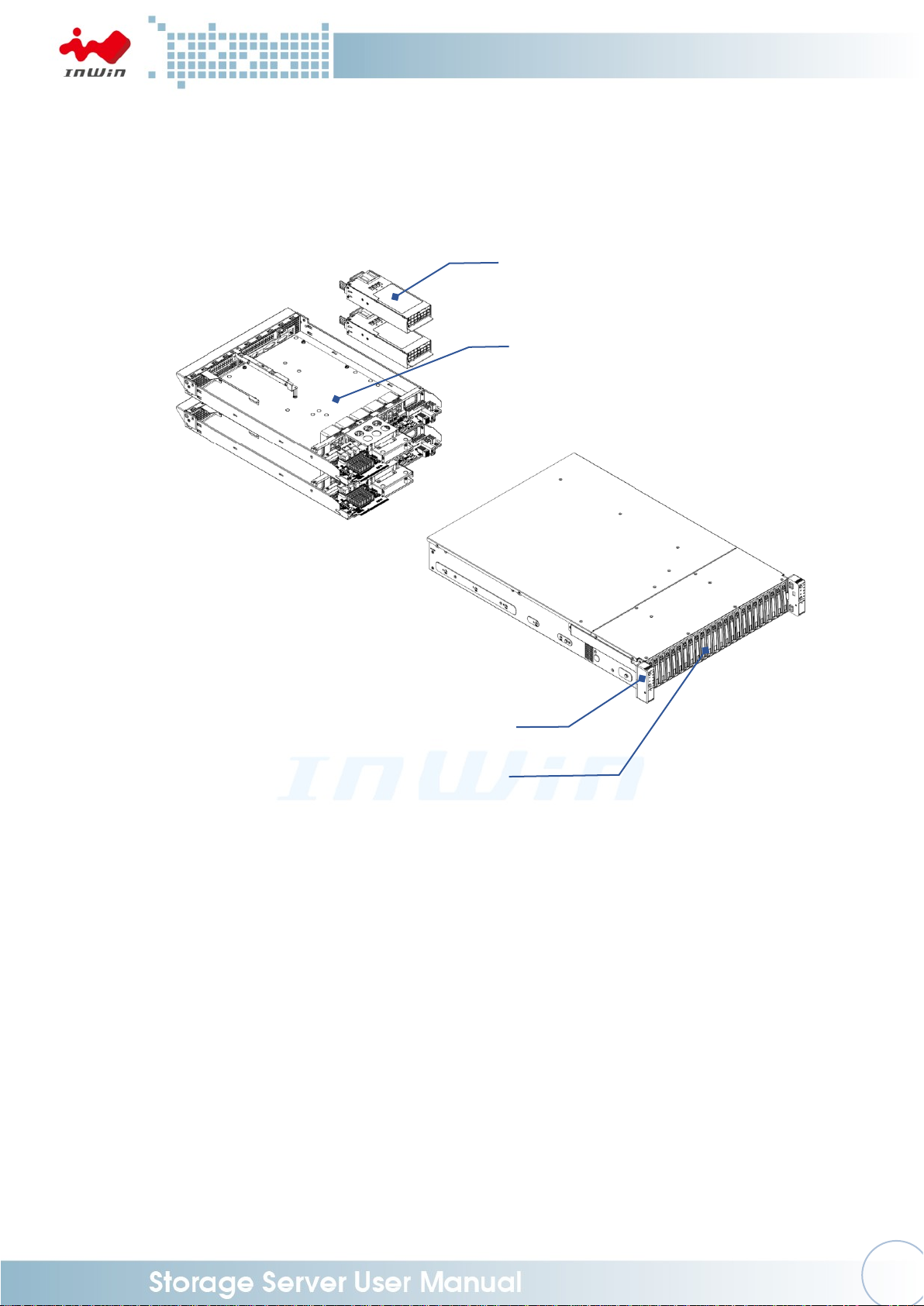
1.2 General Information
The diagram below reflects the chassis opened.
ATX or EEB M/B node x 2
CRPS redundant power supply x 2
Front controls and indicators (Left & Right)
24 x 2.5” tool-less HDD slots
Page 9
6
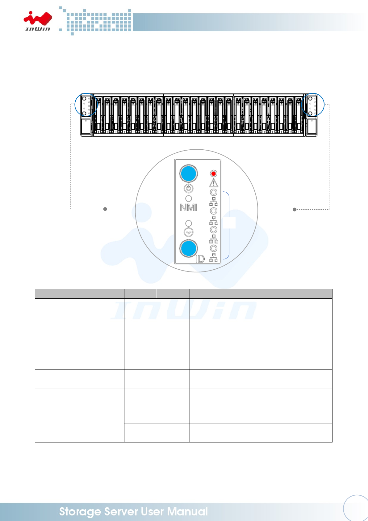
1.2.1 Front Panel Controls and Indicators
The front panel includes control buttons and LED indicators.
Name
Color
Status
Description
1
Power On/Off Button
with LED
Blue
Solid on
System is powered on
N/A
Off
System is off
2
NMI Button
N/A
Press the button to activate user define
3
System Reset Button
N/A
Press the button to activate system reset
4
Chassis ID Button
with LED
Blue
Solid on
Press the button to activate system
identification
5
System Fail LED
Red
Solid on
Indicates system failure (Beeper)
6
LAN LED (From top to
bottom ranked LAN1 LAN4)
Amber
Blinks
Link between system and network
N/A
Off
No data transmission or receiving is
occurring
❶
❷
❸
❹ ❺ ❻
Page 10

7
1.2.2 Rear Panel Configuration
No.
Name
Description
1
Power Module 1
Default primary power supply module.
2
Power Module 2
Backup power supply module.
3
1 Full Height PCI E Slot
The slot supports full height cards. The bracket should be
removed before using.
4
1 Low Profile PCI E Slot
The slot supports low profile cards. The bracket should be
removed before using.
5
Phone Jack for RS232
It connects to expander via RS232 port, which support
monitor expander status.
3
5
4
2
1
3
4
5
Page 11

8
2 Hardware Installation
2.1 Removing and Installing a Hard Drive
The IW-RN224-03’s Dual Node Storage Server features tool-less trays. Users no longer
need to use screws to mount disks, and can swap drives faster.
2.1.1 Installing a Hard Drive
Step 1: Press the release button then pull outward on the handle.
Step 2: Place the 2.5" HDD into the tray.
Step 3: Insert the HDD tray to the slot.
Step 4: Push back the tray cover until it clicks.
Step 1
Step 2
Step 3
Step 4
Pull
Push
Press
Press
Page 12

9
2.1.2 Removing a Hard Drive
Step 1: Press the release button then pull outward on the handle.
Step 2: Pull out the hard drive.
Step 1
Step 2
2.2 Removing and Placing the M/B Node
Step1: Loosen the M/B tray thumb screw.
Step2: Pull down the M/B tray handle.
Step3: Pull out the M/B tray and replace M/B.
Step 1
Step 2
Step 3
Press
Pull
Press
Pull
Pull
Page 13

10
2.3 Removing and Installing the Fan Module
The IW-RN224-03’s built-in fan modules feature a tool-less design, which makes it easy
to maintain.
2.3.1 Removing the Fan Module
Step 1: Pull out the fan module from the fan slot on the motherboard tray.
Step 1
2.3.2 Installing the Fan Module
Step 1: Hold and put the fan module into the fan slot.
Step 2: Connect the fan to the motherboard.
Step 1
Step 2
Pull
Page 14

11
2.4 Removing and Installing the PSU Module
The IW-RN224-03 features a built-in redundant power supply unit. With this function,
the system is capable of still operating if one of the modules fail. To replace it, the user
only needs to release the failed module, then insert a functional module.
2.4.1 Removing the PSU Module
Step 1: Press the release tab at the back of the power supply unit’s module.
Step 2: Pull the module out using the handle.
Step 1
Step 2
2.4.2 Installing the PSU Module
Step 1: Make sure the label is facing upward, and push the power supply module
into the cage until it clicks.
Step 1
NOTE: 1. The unit supports InWin PSU modules only, please do not attempt to insert any
other module brands.
2. The two PSU modules’ output wattage must be the same.
Press
Press
Pull
Push
Press
Press
Press
Page 15

12
2.5 Installing the Motherboard
Step 1: Remove the plastic dots that are covering the motherboard mounting holes.
Step 2: Secure the standoffs on the M/B tray which match with the M/B fixed points.
Step 3: Align the motherboard down to the chassis.
Step 4: Fasten the screws to secure the motherboard in the chassis.
2.6 Connecting Cables
2.6.1 Connecting Expander Through SAS Connectors
Use the SAS 8643 cable to connect the expander to the motherboard.
Use ports 2 and 3 to connect the motherboard or RAID controller, and port 1 for
cascading.
Page 16

13
2.6.2 Connecting LEDs, Front Control Panel and Front USB
Refer to your motherboard user guide for pin functions and locations, then plug
the connectors to the pins on the motherboard to activate the functions.
Connector Name
Abbreviation
Color
Front I/O Indication
Power Switch
PWR SW
Brown
Power ON/OFF Button with LED
Power LED
PWR LED
Purple
Power ON/OFF Button with LED
NMI Switch
NMI SW
Yellow
NMI Button
Reset Switch
RST SW
Orange
System Reset Button
ID Switch
ID SW
Blue
Chassis ID Button with LED
ID LED
ID LED
Green
Chassis ID Button with LED
Alarm LED
ALM LED
Red
System Failure LED
LAN 1 LED
LAN1 LED
Gray
LAN LED
LAN 2 LED
LAN2 LED
Gray
LAN LED
LAN 3 LED
LAN3 LED
Gray
LAN LED
LAN 4 LED
LAN4 LED
Gray
LAN LED
USB 3.0 Connector
None
Black Flat
USB 3.0
Mute Switch
Mute
White
Mute Switch
LED Connector
USB 3.0
Page 17

14
2.7 Installing the Slide Rail
The IW-RN224-03 is a rackmount model, which support EIA-RS310D standard cabinets
and chassis racks. InWin provides standard slide rails for mounting the RN224-03 Node
storage chassis to cabinets.
2.7.1 Identifying the Slide Rail
The slide rail you order might be different. Follow the quick installation guide
inside the slide rail package and follow the instructions to mount the rail on to
your cabinet or chassis rack.
2.7.2 Removing the Inner Rail and Sliding the Intermediate Rail Back
Step 1: Pull out the inner rail until it reaches the stop. Release the blue slide tab to
unlock.
Step 2: Continue pulling the inner rail until the second stops. Release the white
slide tab to remove the inner rail.
Step 3: Pull the latch on the middle rail upward and retract the middle rail back.
Step 1 ~ 2
Step 3
2.7.3 Attaching the Inner Rail to the Chassis
Step 1: Align the chassis sidewall standoffs to the inner rail keyholes. Slide the
inner rail toward the front until the standoff snaps into place, securing the
rail to the chassis.
Step 2: Repeat the same action on the other side.
Step 3: When removing the inner rail:
Pull up the latch and slide the inner rail forward. Remove the keyhole from
the standoff to detach the inner rail. (Action and in the figure)
Step 1 ~ 2
Page 18

15
Step 3
2.7.4 Attaching the Inner Rail to the Chassis
Step 1: Extend the rail bracket over the rear rack of the cabinet.
Step 2: Pull out the rear hook on the end of the outer rail, align and push the rail
bracket pins into the post holes on the rack. Then, pull back the hook on
the end of the outer rail.
Step 3: Extend the opposite side of the rail bracket to the front rack of the cabinet.
Step 4: Hang the front hooks of the outer rail at the front of the rack post holes.
Pull the rail bracket pins that go into the front post holes on the rack until
they click.
Step 5: The other side of the rail is symmetrical, repeat the installation steps 1-4.
Step 6: Once you would like to detach the bracket, pull outward on the front and
rear hooks of the outer rail to release the bracket. Repeat the same action
to the other side.
Step 1 ~ 5
Step 6
Page 19

16
2.7.5 Inserting the Chassis to the Cabinet
Step 1: Pull out the middle rail to the stop position.
Step 2: Move the ball bearing retainer to the front end of the middle rail, it should
click into the locked position.
Step 3: Insert the inner rails of the chassis into the middle rails on the both sides of
the rack.
Step 4: Push the chassis to the stop position, then release the blue slide tab (by
either pulling the tab forward or pushing the tab back) to continue.
Step 5: Release the blue slide tab again to continue until reaching the second stop
position.
Step 6: Push the chassis into position on the rack completely. Make sure that the
front end of the chassis is aligned with the edge of the rack to complete
the installation.
Page 20

17
3 Backplane Introduction
Location
Description
CN01-CN12
SAS Receptacle Connector (SAS 12Gb/s 3.5" HDD Connector)
Dxx1
HDD Power LED
Dxx2
HDD Access/Fault LED
CNE1
Primary SAS Expander Slot
CNE2
Secondary SAS Expander Slot
FPC1
Front Switch FPC/IO Board Connector
PW1
ATX 2x7P 5V Power Connector
PW2
ATX 2x8P 12V Power Connector
J1
Server Mute SW Connector
JM1
Server/JBOD (Pin 1-2: JBOD / Pin 2-3: Server)
JM2
HDD LED Behavior (Pin 1-2: Default / Pin 2-3: Proprietary)
JC1
PDB Control Connector
B1
Global Fail Warning
Page 21

18
4 Expander Board Introduction
4.1 Key Features
■ Reliable High Data Rate Support (up to 12Gbps)
- SAS 12Gbps support and SATA3 6Gbps support to provide a reliable, highperformance data rate.
■ Hot-swappable HDDs
- Quickly swap your HDDs. No need to shut down your system for HDD installation
and/or replacement while an HDD failure is present or while adding a new HDD to
the system.
■ Cascading
- There is a cascading port on the Expander for cascading to another Expander for
expanding disk space.
Page 22

19
4.2 UART Usage
4.2.1 UART configuration
The RS-232 UART port on the expander module provides a serial connection for
users to manage terminal applications such as: Tera Term, Hyper Term…etc.
To manage Expander through the UART port, the settings below must be properly
configured to function.
Baud Rate : 115200
Data : 8 bit
Parity : None
Stop Bit : 1 bit
Flow Control : None
When connected, there is a prompt display on the terminal, then users can start typing
CLI commands.
Page 23

20
4.2.2 System Revision
To check the Expander revision, type “rev” and “sys rev” to get the expander
information such as Vendor ID, Firmware Version, SAS Address, …etc.
Page 24

21
4.2.3 System Monitoring
To monitor the enclosure sensor status, such as temperature and DC power
amplitude, type command “sys” in the UART.
Page 25

22
4.2.4 Disk PHY Status
To monitor the SAS PHY status, type “Phyinfo” or “sys hdd” to check. Users can
check the disk link status by using these commands.
Page 26

23
4.2.5 Firmware Update
In some occasions, when required, users can update expander firmware through
UART port via Xmodem protocol.
* A power interruption or failure during firmware upgrade will cause damage to
the device or unrecoverable data errors.
There are 2 firmwares for expander. Be sure these binary files are available in the
host before conducting firmware updates.
1. SAS Expander Operation Firmware
2. SAS Expander MFG CFG binary
The updated firmware does not take effect until a reset (either system reboot or
reset expander via CLI command – “reset”).
4.2.5.1 SAS Expander Operation Firmware Update
A. “fwdl” command on terminal.
B. Type “y” to commit firmware upgrade.
C. Select Xmodem as the protocol to transfer file.
D. Select the correct SAS Expander firmware file.
Page 27

24
E. Click on “Open” to start the selected firmware transferring to SAS
Expander.
F. Terminal would then start firmware transfer.
G. After firmware transfer is completed, type the ‘reset’ command in the
terminal or power cycling system to activate the new firmware.
Page 28

25
4.2.5.2 SAS Expander MFG CFG Binary Update
A. Similar to operation firmware upgrade, type “mfgdl” on console.
B. Type “y” to commit MFG file upgrade.
C. Select Xmodem as the file transfer protocol.
D. Select the correct MFG, CFG file from the file browser.
E. Click “Open” to start file transfer.
F. Terminal should then start file transfer.
G. After the firmware transfer is completed, type the ‘reset’ command in the
terminal or power cycling system to activate the new firmware.
Page 29

26
5 Compatibility Lists
To reach the best performance and avoid system failure, InWin strongly recommends users to
choose the components from InWin’s compatibility list. All the components are tested in
InWin’s lab, and assured the components are complementary with InWin’s chassis.
You can download the latest updated device compatibility list from InWin’s website:
https://www.in-win.com/en/ipc-server
6 Q&A
Section 1: Expander
1. What is the InWin expander’s function?
A: Expanded capacity, the expander can manage more SAS drives through a SAS cable.
2. Why is the IW-RN series storage server chassis built-in expander boards, and the IW-RJ
series JBOD enclosures using expander modules?
A: The IW-RN chassis needs a motherboard to compose a system, the expander board
can work seamlessly with the motherboard to manage the drives. The IW-RJ JBOD
enclosures use hot-swappable expander modules to satisfy the requirements of both
capacity expansion and JBOD redundancy.
3. Once I find that the expander is failing, what can I do?
A: Power off the system, and make sure the system is completely shut down. Unplug the
SAS cable to replace the expander board.
Section 2: Hard Disk
4. What is the difference between SAS and SATA disk, and how to choose?
A: SATA has only one throughput channel for data transmission, SAS has two. Once the
system is designed with redundant functionality, SAS disk provides performance and
reliability. SATA provides a cost selective option.
5. Are SAS and SATA disks compatible with InWin IW-RN series?
A: Yes, InWin IW-RN series support both SAS and SATA disks.
6. Can I mount 2.5” disks to 3.5” tool-less slots?
A: The 3.5” tool-less slots do not support 2.5” disks at this moment. If this requirement is
mandatory, please contact InWin sales for OEM service.
7. If my system drive fails, can I replace the drive without shutting down the system?
A: By default, the IW-RN series’ two internal disks don’t support hot-swap feature. You
can order an optional 2-bay hot-swap system disk module to reach your purpose.
Page 30

27
Section 3: Two nodes
8. Does the Dual Node Rackmount Storage Server Support a hot-swappable function?
A: Yes, it supports a hot-swappable function.
9. Does the Dual Node Rackmount Storage Server have independent power on and shut
down the system?
A: Yes, it can have independent power on and shut down the system.
10. Does the Dual Node Rackmount Storage Server support single node operation?
A: Yes, it can support single node operation.
Section 4: Other
11. Why does the PSU have two modules? What are these two modules for?
A: Two PSU modules are used for redundancy. If you need this function, a PSU with two
modules are required.
12. Can I add or reduce the quantity of fans?
A: The quantity of fans are related to the radiating efficiency. Usually, the quantity of fans
depends on the system loading and the heat generation. Unless you have already tested,
we strongly recommend not to change the default fans quantity.
13. Which parts support the hot-swap feature?
A: The IW-RN storage server uses this feature for the following parts: Fans, PSUs and
HDDs.
14. If the arm or handle is broken, how can I repair or replace it?
A: Please contact your local InWin partner, or contact support for replacement and repair
services.
7 Technical Support
If you need help with installation or troubleshooting, you can contact your local InWin partner,
or send an e-mail to InWin’s local contacts for technical assistance.
 Loading...