

Page 1

IW-RJ448-05
User Manual
Page 2

Table of Contents
PREFACE ....................................................................................................................................... 1
SAFETY INFORMATION ................................................................................................................. 1
CAUTION ...................................................................................................................................... 2
SPECIFICATIONS ............................................................................................................................ 3
1 Product Introduction ............................................................................................................. 4
1.1 Box Contents ............................................................................................................................ 4
1.2 General Information ................................................................................................................. 5
1.2.1 Front Panel Controls and Indicators ......................................................................................................... 6
1.2.2 Rear Panel Configuration .......................................................................................................................... 7
1.2.2.1 Expander (Host) Configuration ................................................................................................................. 8
2 Hardware Installation ........................................................................................................... 9
2.1 Removing and Installing a Hard Drive ........................................................................................ 9
2.1.1 Open the HDD Drawer .............................................................................................................................. 9
2.1.2 Close the HDD Drawer .............................................................................................................................. 9
2.1.3 Installing a Hard Drive .............................................................................................................................. 9
2.1.4 Removing a Hard Drive ........................................................................................................................... 11
2.2 Removing and Installing the Fan Module................................................................................. 11
2.2.1 Removing the Fan Module ..................................................................................................................... 11
2.2.2 Installing the Fan Module ....................................................................................................................... 12
2.3 Removing and Installing the PSU+FAN Module ........................................................................ 13
2.3.1 Removing the PSU+FAN Module ............................................................................................................ 13
2.3.2 Installing the PSU+FAN Module .............................................................................................................. 13
2.4 Removing and Installing the Host & Disk Expander Module .................................................... 14
2.4.1 Removing the Host Expander Module ................................................................................................... 14
2.4.2 Installing the Host Expander Module ..................................................................................................... 15
2.4.3 Removing the Disk Expander Module .................................................................................................... 15
2.4.4 Installing the Disk Expander Module ..................................................................................................... 17
2.5 Rail Installation ....................................................................................................................... 18
2.5.1 The Type of Rail Kit ................................................................................................................................. 18
2.5.2 Fixed Rail Blade ....................................................................................................................................... 18
2.5.2.1 Installing the Fixed Rail Blade to the Rack ............................................................................................. 18
2.5.2.2 Insert the Enclosure to the Rack............................................................................................................. 18
Page 3

3 Expander Board Introduction (Host & Disk) ......................................................................... 21
3.1 Expander Board (Host) ............................................................................................................ 21
3.2 Expander Board (Disk) ............................................................................................................ 22
4 User Interface Introduction ................................................................................................. 23
4.1 Overview ................................................................................................................................ 23
4.2 Key Features ........................................................................................................................... 23
4.3 Software Management ........................................................................................................... 24
4.3.1 System Management Structure .............................................................................................................. 24
4.3.2 Serial Port Management ......................................................................................................................... 25
4.3.3 Network Management ........................................................................................................................... 28
4.3.4 Version Information ................................................................................................................................ 34
4.3.5 System Status .......................................................................................................................................... 35
4.3.6 Network Settings .................................................................................................................................... 37
4.3.7 Disk Information ..................................................................................................................................... 38
4.3.8 Zone Setting ............................................................................................................................................ 39
4.3.9 Firmware Upgrade .................................................................................................................................. 42
4.3.10 Web Console ........................................................................................................................................... 48
4.3.11 Advanced Configuration ......................................................................................................................... 49
4.4 Appendix A ............................................................................................................................. 52
4.5 Appendix B ............................................................................................................................. 52
5 Compatibility Lists .............................................................................................................. 54
6 Technical Support ................................................................................................................ 54
Page 4

1
PREFACE
Thank you for choosing the InWin IW-RJ448-05. This manual is written for system technicians who
are responsible for installation, troubleshooting, managing and repairing this server chassis. This
document provides the overview of all the features of the chassis, a list of accessories or other
components you may need to finish the installation, troubleshooting methods and instructions on
adding and removing components on the InWin IW-RJ448-05. For the latest version of this manual,
you may visit InWin’s server website to download the latest updated version.
SAFETY INFORMATION
To ensure a safe and smooth operation of your InWin IW-RJ448-05, it is essential that you choose
an appropriate location for the system, provide an appropriate operating environment and supply
an adequate amount power for all components of the system. As you plan for installation, follow
the guidelines below to ensure that the system and its environment are safely and appropriately
positioned for efficient operation and service. Your system should be installed and serviced only by
a qualified technician.
Environment selection: The system is designed to operate in a typical office environment:
• The location should be clean, dry and free of airborne particles.
• It should be situated in a well-ventilated room, and away from sources of heat including direct
sunlight and radiators.
• It should be kept away from sources of vibration or physical shock.
• The space should be accommodated with a properly grounded wall outlet, and with sufficient
space to access the power supply cords.
• The operating environment temperature should be around 0°C to 40°C (32°F to 104°F).
Heed safety instructions: Before working with InWin IPC/Storage server products, we strongly
recommend you use this guide as a reference and follow the safety instructions. The instructions in
this manual will help you ensure and maintain compliance with existing product certifications and
approvals. Follow the described, regulated components mentioned in this manual. Use of non-UL
listing products or other regulators may not comply with product regulations in the region(s) in
which the product is sold.
System power on/off: The power button DOES NOT totally turn off the system AC power. To
remove the power of the system, you must unplug the AC power cord from the outlet or the
system’s power supply units. Make sure the power cord is unplugged before you open the chassis
or add/remove any components.
Hazardous conditions, devices and cables: Hazardous electrical conditions can be present on/in
power supply units and their cables. Disconnect the power cord and any other device attached to
the server before opening the case. Failing to follow safety procedures will increase the risk of
personal injury or equipment damage.
Page 5
2
1. Do not populate hard drives and turn on the power until the system has
stabilized.
Make sure hard drives and other components are properly connected before
turning on the system.
2. Tighten or loosen all screws with a screwdriver.
3. Apply the correct screws packed in the accessory box.
4. For your safety, please have at least two people lift and place the unit in its
designated area.
5. Before mounting the unit to the cabinet, make sure the rail is installed correctly.
6. When installing and removing any module or part, please use the handles.
Electrostatic discharge (ESD) and ESD protection: In most cases, ESD may damage disk drives,
electronic boards and other parts. We recommend that you conduct installation only at an ESD
free space. If not possible, perform ESD protection protocol by wearing an anti-static wrist straps
attached to the ground on any unpainted metal surface on your server during operation.
Installing or removing jumpers: A jumper is a short length conductor used to close, open or bypass
part of an electronic circuit. Jumpers on InWin backplanes have a small tab on top that you can
pick up with your fingertips. Grip the jumper carefully and plug the jumper to cover the jumper
pins on the backplane. Once you need to remove the jumper, grip the jumper and carefully pull
without squeezing.
CAUTION
To avoid damage and maintain your safety, please read the following terms listed below:
Page 6
3
Model Name
IW-RJ448-05
Standard
EIA-RS310D
Dimensions (D x W x H)
w/o Front Door
736.6 x 482.6 x 176 mm
(29" x 19" x 7")
Storage
External: Hot-swap 3.5" x 48 (SAS 12Gbps)
Power Supply
(PSU+FAN Modules)
Supports
▪ Form Factor: High efficiency redundant PSU
▪ Watt: 1100W
Cooling Fan
(PSU+FAN Modules)
80 x 38 mm PWM x 6
12G Expander Module
1 or 2
Host/Expansion Port
6 x Mini SAS HD (SFF-8644) for each 12G expander module
Management
Smart fan, thermal monitor, HDD monitor, voltage monitor, alarm
warning
SES
Supports SES-2 (SCSI Enclosure Service)
Maintenance
Supports management by Ethernet (Optional) and RS-232
HDD Power Management
HDD sequential power on
Temperature
0ºC to 35ºC
Material
Material: SGCC
Thickness: 1.6 mm
Rail Kit
Fixed rail blade
SPECIFICATIONS
* The actual product is subject to change without prior notice. In Win Development Inc. reserves the
right to make any final modifications.
Page 7
4
1 Product Introduction
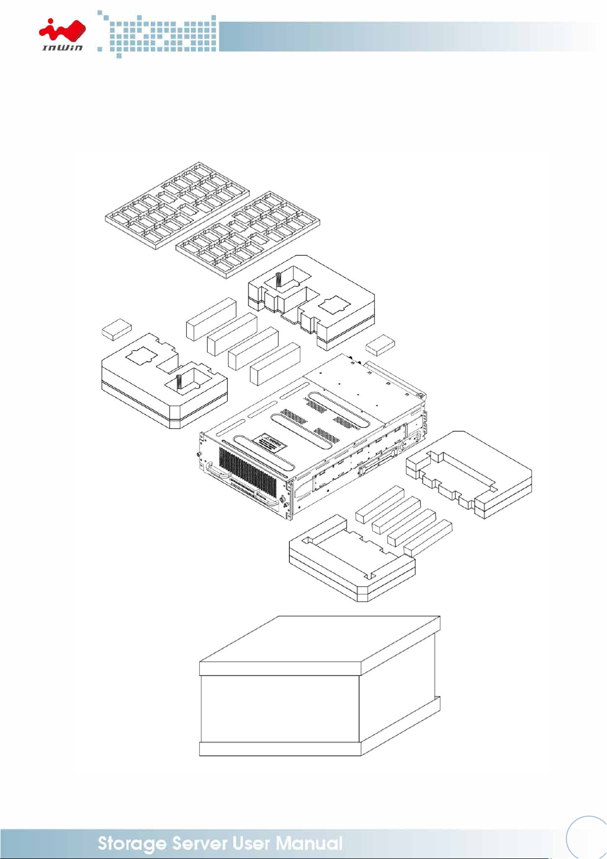
1.1 Box Contents
Page 8
5
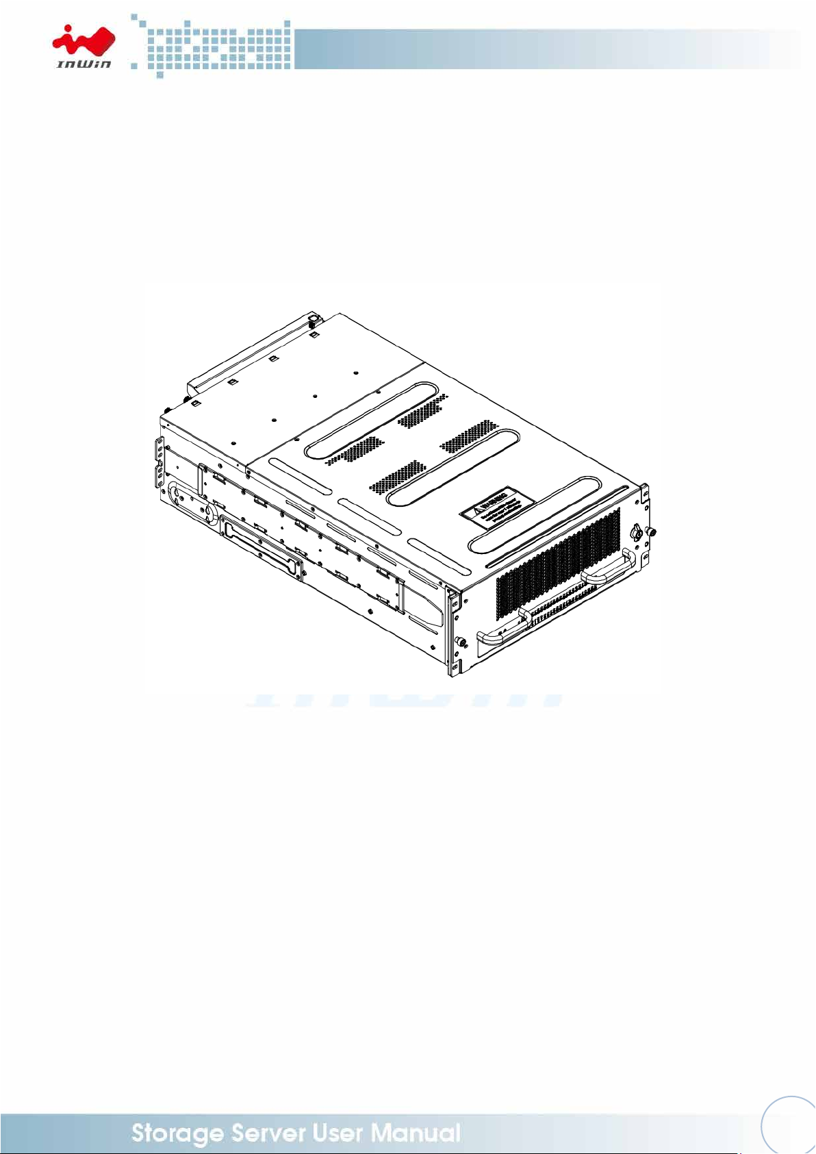
1.2 General Information
Designed for high scalability and high availability in storage applications, the IW-RJ448-05 JBOD
enclosure is a high density 4U rackmount storage chassis with 48 tool-less bays. It features dual
hot-swap SAS 12G expander modules, six Mini-SAS HD (SFF-8644) for each 12G expander
module, six PSU +Fan module fans, dual redundant 1100W power + fan module, and GUI
supports via Ethernet board (Optional).
Page 9
6
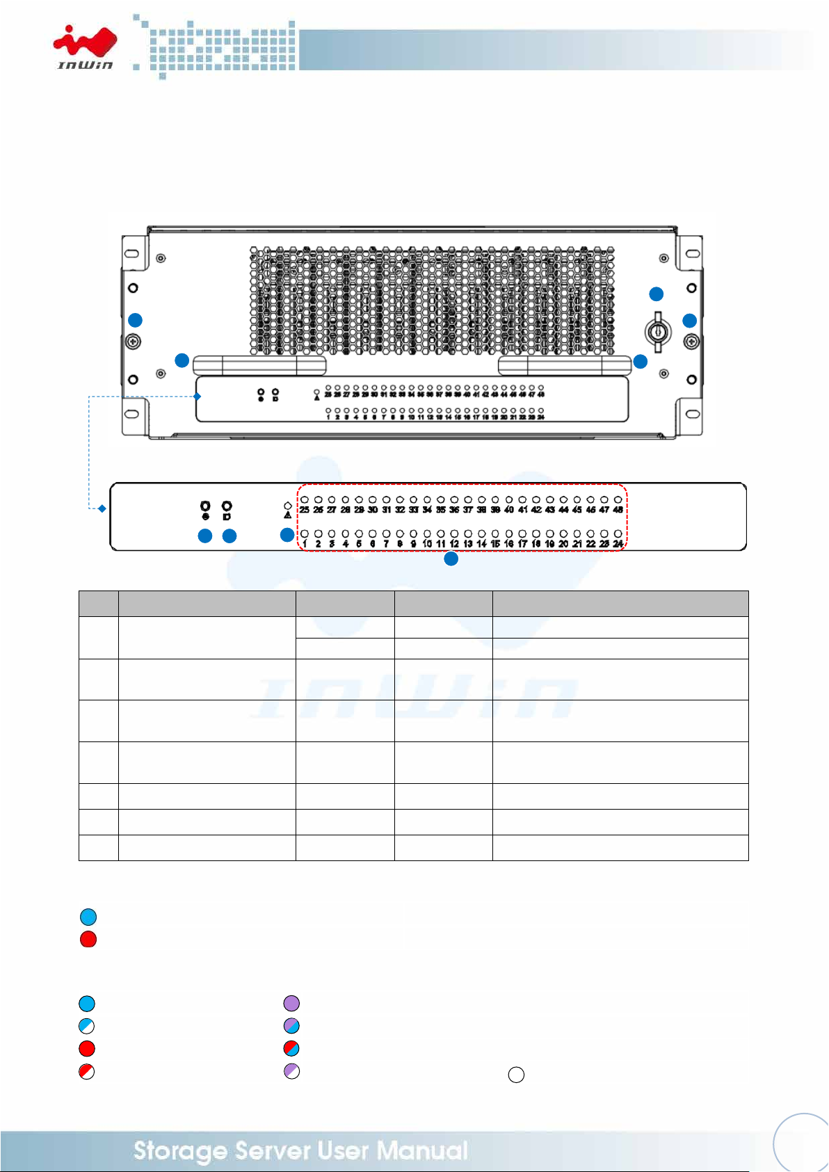
No.
Name
Color
Status
Description
1
Power On/Off Button
with LED
Blue
Solid on
System is powered on
N/A
Off
System is off
2
Chassis ID Button with
LED
Blue
Solid on
Press the button to activate chassis
identification
3
Status LED
Red
Solid on
System maintenance (PSU, fan
malfunction)
4
Drives Status LEDs for
Bays 1-48
Follow the
table below
5
Drawer Lock
6
Drawer Thumbs Screw
7
Drawer Handle
System Healthy
System Maintenance (PSU, fan malfunction)
(Solid) Drive Online
(Solid) RAID Drive
(Blink) Drive Activity
(Blinking Purple on Solid Blue) RAID Active / Rebuild
(Solid) Drive Failed
(Alternating Blink) Drive Faulty / RAID Failure
(Blink) Drive Missing
(Blink) Drive Locate
Drive Offline / Removed
1
2 3 4 5 6 6 7
7
1.2.1 Front Panel Controls and Indicators
The front panel includes control buttons and LED indicators.
Status LED:
Drive Status LED:
Page 10
7
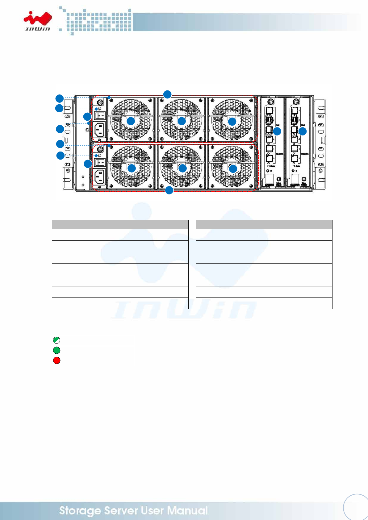
No.
Item
No.
Item
1
Power Module 1 (PSU+FAN Module)
8
Fan Module 6 (PSU+FAN Module)
2
Power Module 2 (PSU+FAN Module)
9
Primary Expander Module
3
Fan Module 1 (PSU+FAN Module)
10
Secondary Expander Module
4
Fan Module 2 (PSU+FAN Module)
11
Power Module Handle
5
Fan Module 3 (PSU+FAN Module)
12
Power Switch
6
Fan Module 4 (PSU+FAN Module)
13
PSU Alarm Mute Button
7
Fan Module 5 (PSU+FAN Module)
14
PSU Status LED
Power Standby
Power On
Loss of Power
3
5
7
4
6
8
9
10 2 1
11
12
13
12
14
14
11
1.2.2 Rear Panel Configuration
PSU Status LED:
Page 11
8
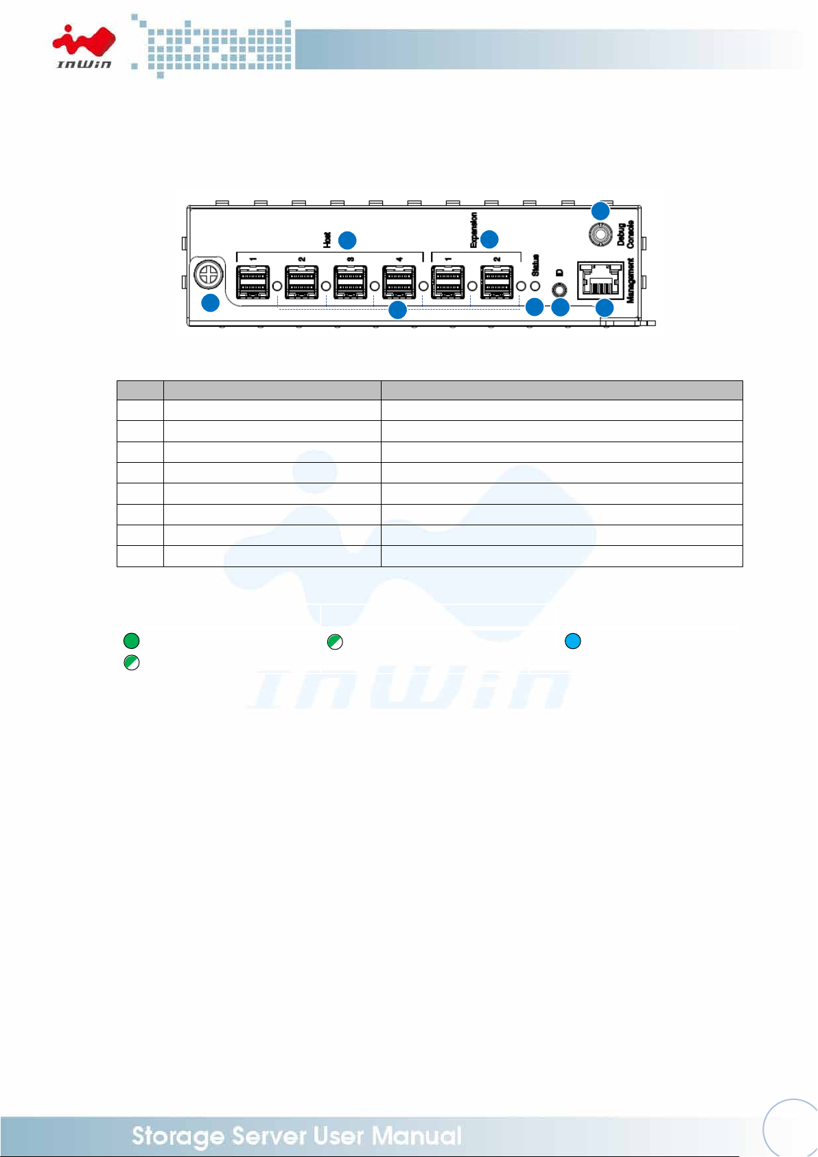
No.
Name
Description
1
SAS Port LEDs
Host HBA/RAID card connection
2
SAS Host Ports
External Uplink, Connect to HBA/RAID card
3
SAS Expansion Ports
External Downlink, Connect to cascading JBOD
4
Expander Module Status LED
Heartbeat
5
ID LED / Button
Press the button to activate chassis identification
6
Expander Serial Port (RS-232)
RS-232 Support
7
Network Management Port
Connect to Ethernet remote monitoring
8
Expander Module Handle
SAS Port LEDs:
Expander Module Status LED:
ID LED:
SAS Connection On
Heartbeat
ID on
SAS Activity
4 7 5 6 2 3 1
8
1.2.2.1 Expander (Host) Configuration
Page 12

9
Step 1:
Step 2:
Step 1:
Step 2:
Pull
Push
2 Hardware Installation
2.1 Removing and Installing a Hard Drive
The IW-RJ448-05 JBOD features tool-less trays, users can easily swap drives without any
screws.
NOTE: Do not leave the HDD drawer open for more than 1 minute to prevent overheating.
2.1.1 Open the HDD Drawer
Step 1: Loosen the keylock and the thumbscrews of the drawer.
Step 2: Pull the HDD drawer outward.
2.1.2 Close the HDD Drawer
Step 1: Push the drawer back.
Step 2: Lock the keylock and tighten the thumbscrews.
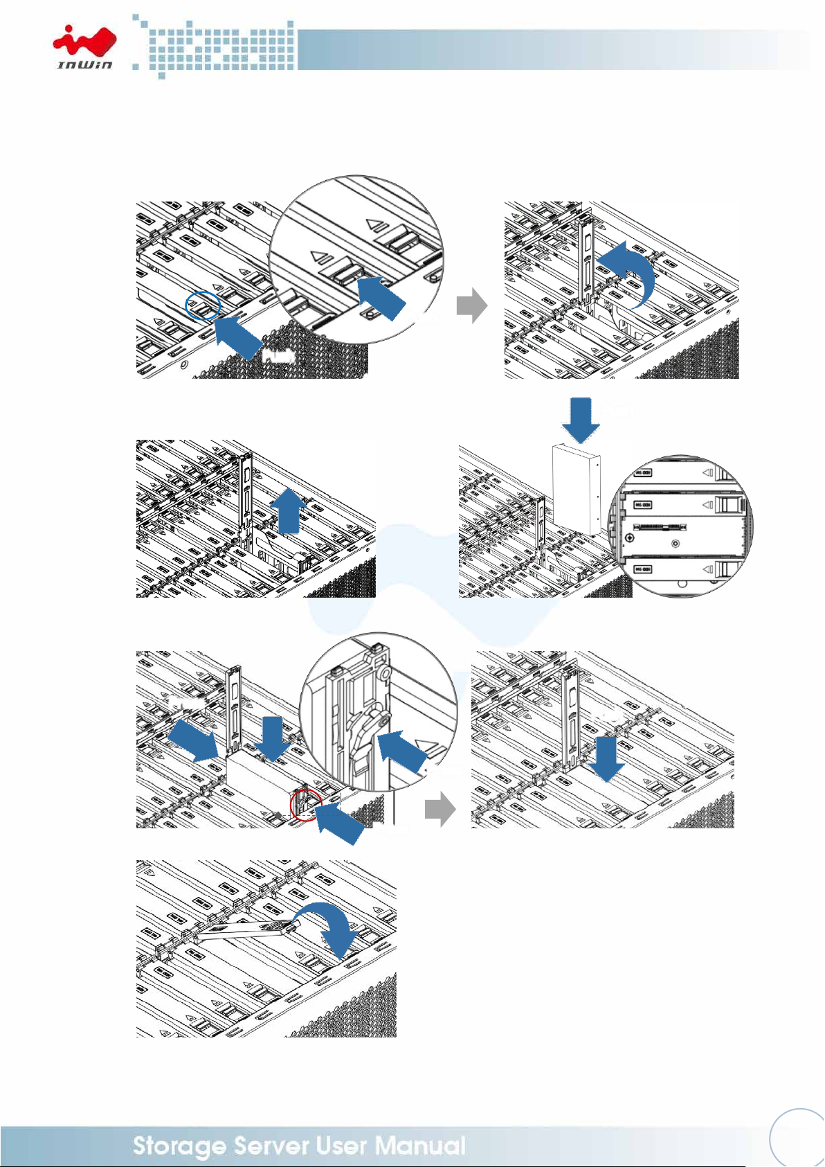
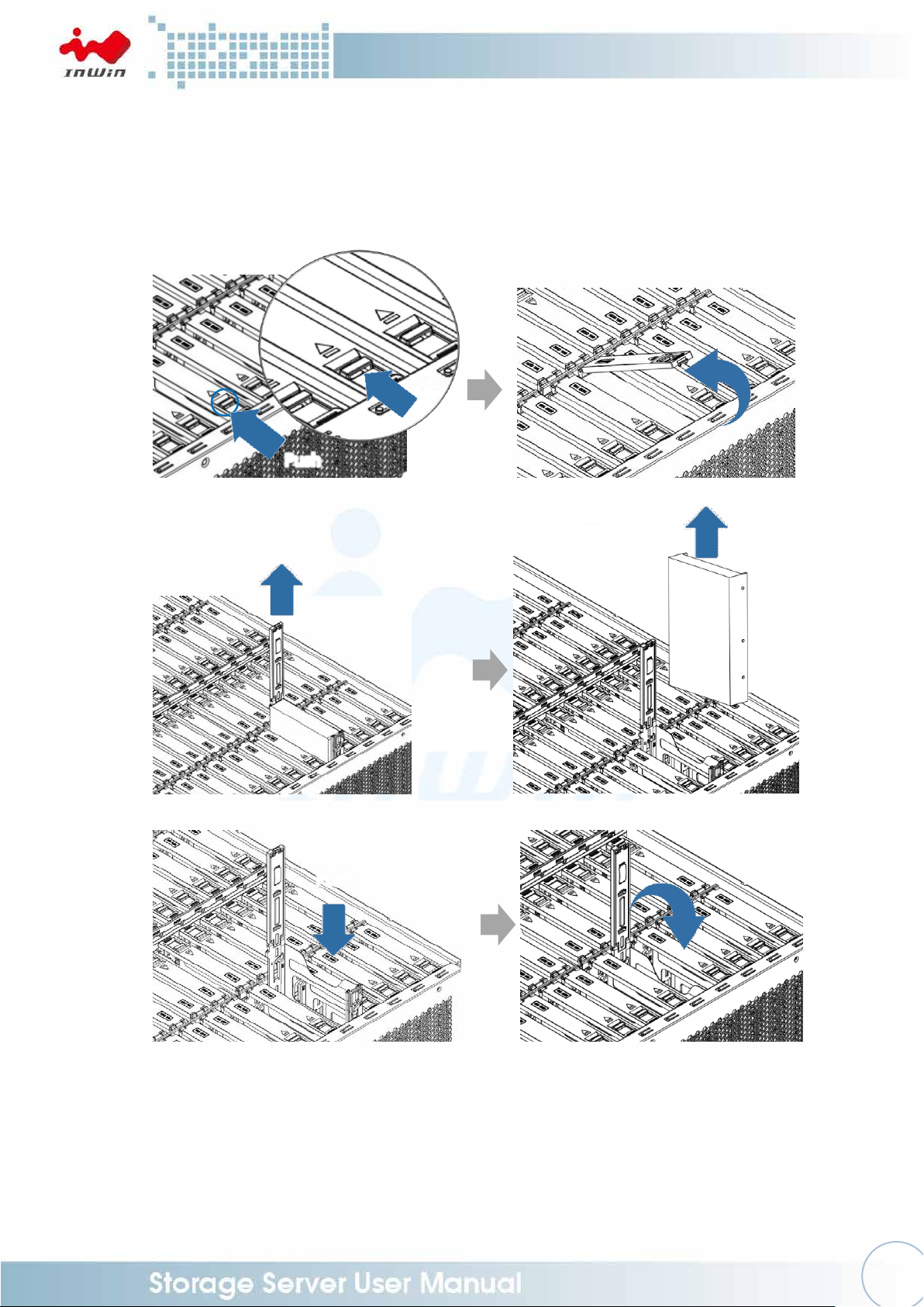
2.1.3 Installing a Hard Drive
Step 1: Release the latch in the direction of the arrow on the tray.
Open the disk tray cover and pull it outward as a handle.
Step 2: Pull up the tray until it clicks.
Step 3: Fully insert the HDD into the tray from the correct disk port orientation.
Page 13
10
Push
Pull
Push
Press
Press
Push
Press
Push
Push
Step 4: Align the HDD screw holes and plug in the pins on the side of the tray.
Keep the tray pins against the HDD screw holes and push the disk tray back
to the location.
Step 5: Release the latch to close the cover to lock.
Step 1:
Step 2 Step 3
Step 4
Step 5
Page 14
11
Pull
Pull
Push
Push
Push
2.1.4 Removing a Hard Drive
Step 1: Release the latch in the direction of the arrow on the tray.
Open the disk tray cover and pull it outward as a handle.
Step 2: Pull up the tray until it clicks.
Step 3: Pull the hard drive out carefully.
Step 4: Lower the disk tray back. Release the latch to close the cover to lock.
Step 1
Step 2 Step 3
Step 4
2.2 Removing and Installing the Fan Module
The IW-RJ448-05 JBOD has built-in fan modules that support hot-swappable and
redundant features, which are easy to maintain with the tool-less design.
2.2.1 Removing the Fan Module
Page 15
12
Pull
Push
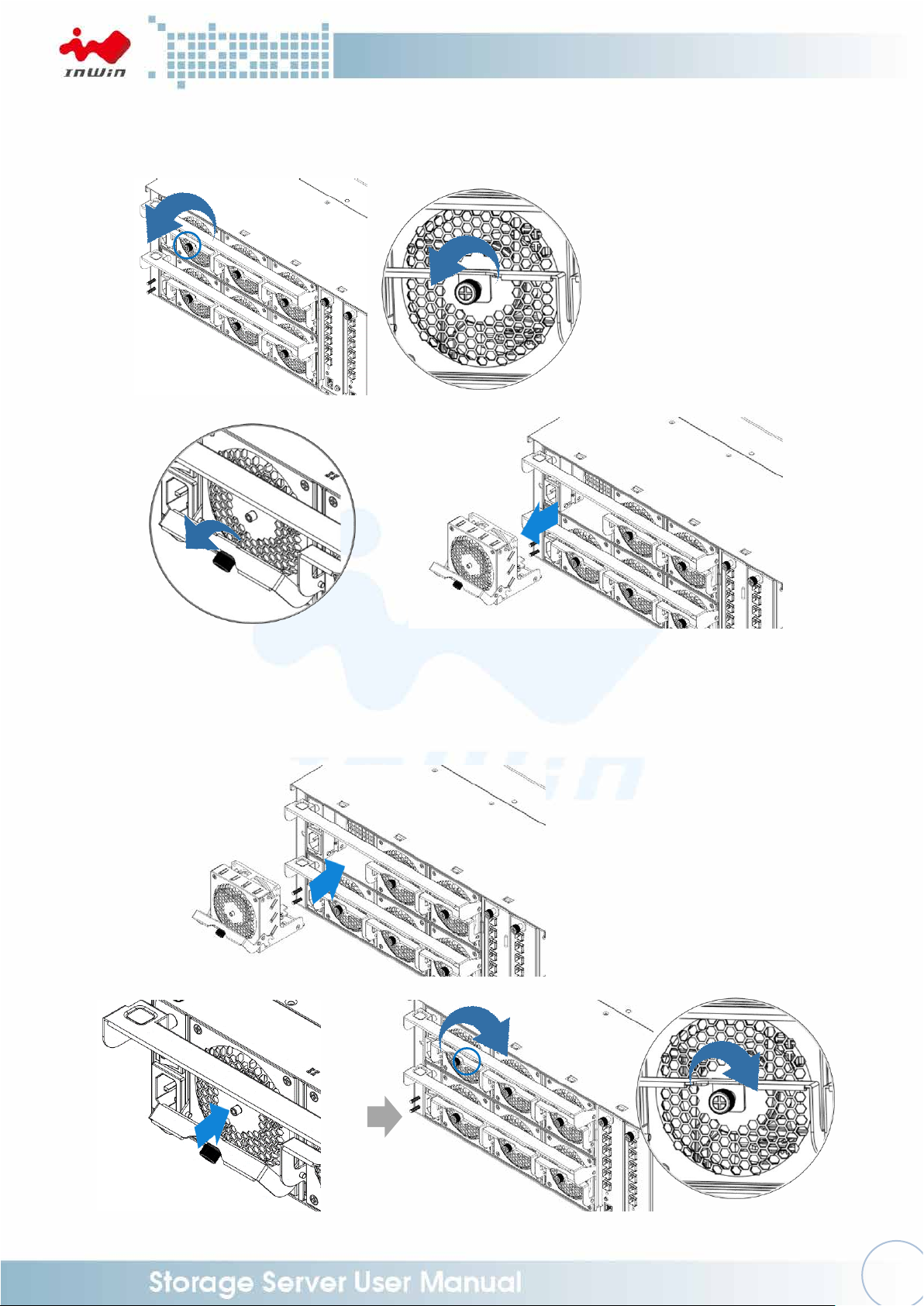
Step 1: Loosen the thumbscrew of the fan module.
Step 2: Press the handle and pull out the fan module with the slot to separate it
from the PSU+FAN module.
Step 1
Step 2
2.2.2 Installing the Fan Module
Step 1: Push the fan module back into the slot until it clicks.
Step 2: Secure the thumbscrews in place and tighten.
Step 3: Connect the fan to the backplane.
Step 1
Step 2
Page 16
13
Push
Pull
PSU
Fan
2.3 Removing and Installing the PSU+FAN Module
The IW-RJ448-05 hosts dual built-in redundant 1100W PSU+FAN modules. Each module
cage contains one 1100W power supply and three fan modules. With this function, the
system is capable of still functioning if one of the modules fail. To replace it, the user
only needs to release the failed module, then insert a functional module.
NOTE: The two PSU modules’ output wattage must be the same.
To ensure the stability of use, if the PSU module fails, it is recommended to replace
the PSU with the fan modules together.
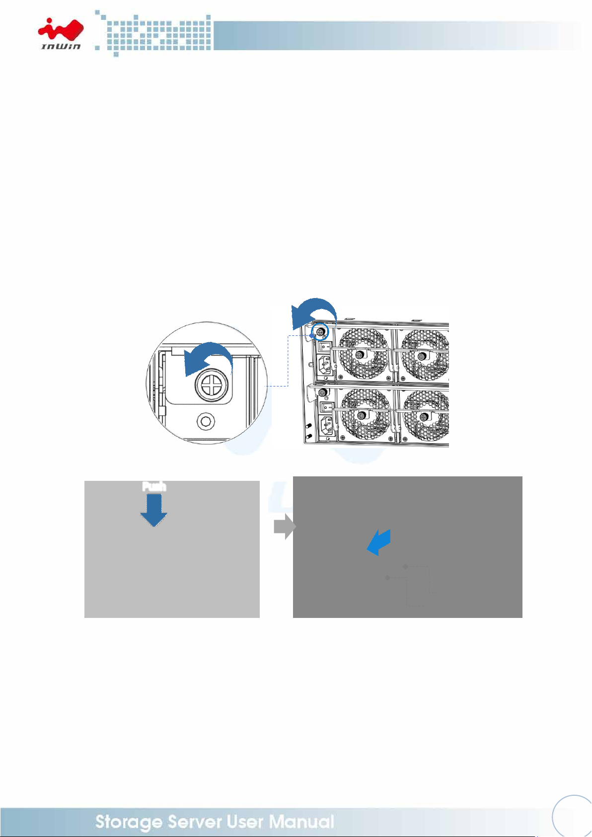
2.3.1 Removing the PSU+FAN Module
Step 1: Loosen the thumbscrew of the PSU+FAN module cage at the back.
Step 2: Push down the handle and use the handle to pull out the cage. Separate
the PSU+FAN module from the enclosure.
Step 1
Step 2
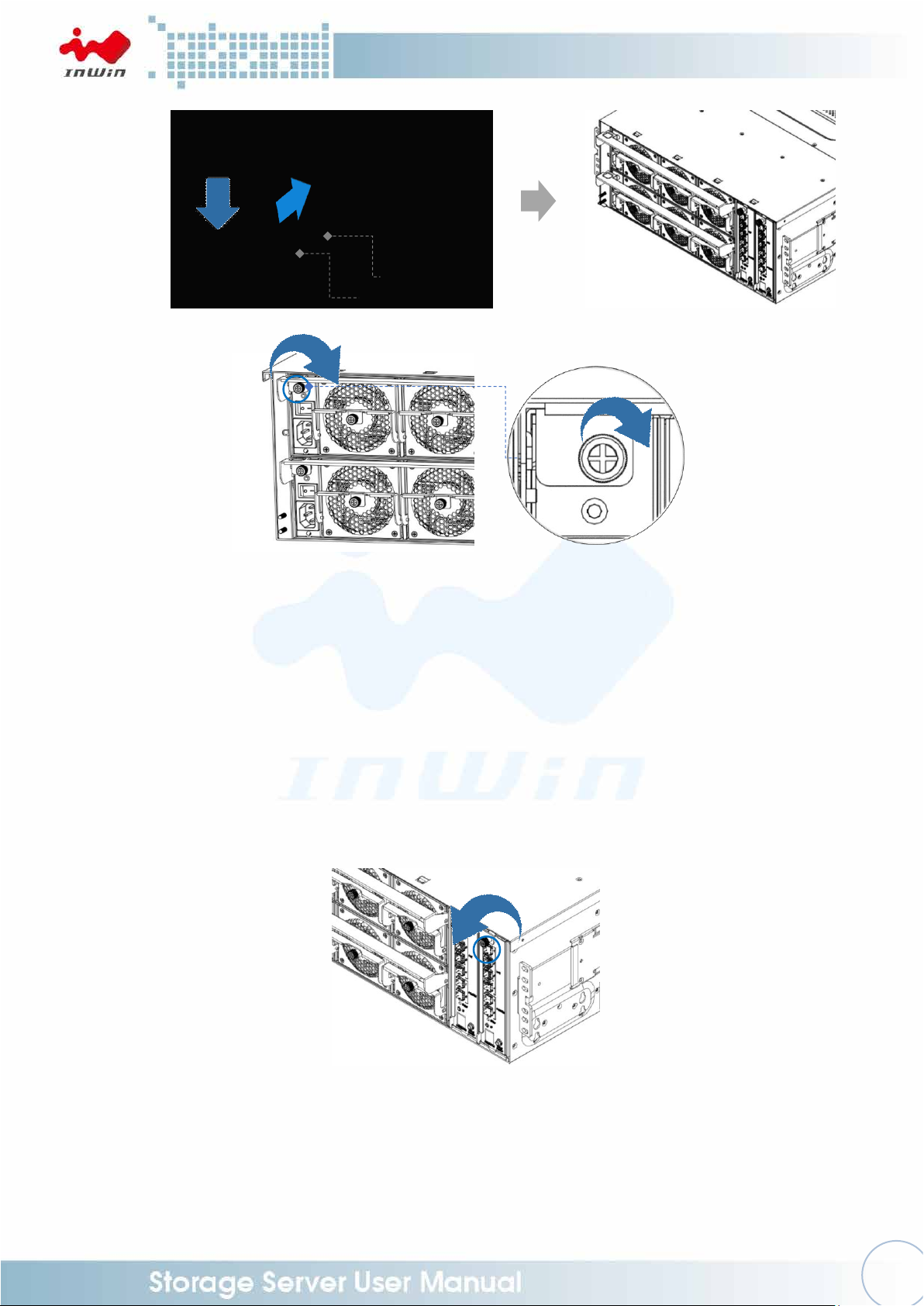
2.3.2 Installing the PSU+FAN Module
Step 1: Push the 1100W PSU+FAN module into the cage until it clicks back the
original location.
Step 2: Tighten the thumbscrew to secure the cage.
Page 17
14
Push
PSU
Fan
Step 1
Step 2
2.4 Removing and Installing the Host & Disk Expander Module
The IW-RJ448-05 JBOD is accommodated with pre-installed dual redundant host
expander and four redundant disk expander modules. The internal expander is primary,
and the external expander will be the secondary. The host expander module includes an
Ethernet management module, which allows users to monitor and maintain the system.
Also, the redundant module can minimize downtime should any of the expanders fail.
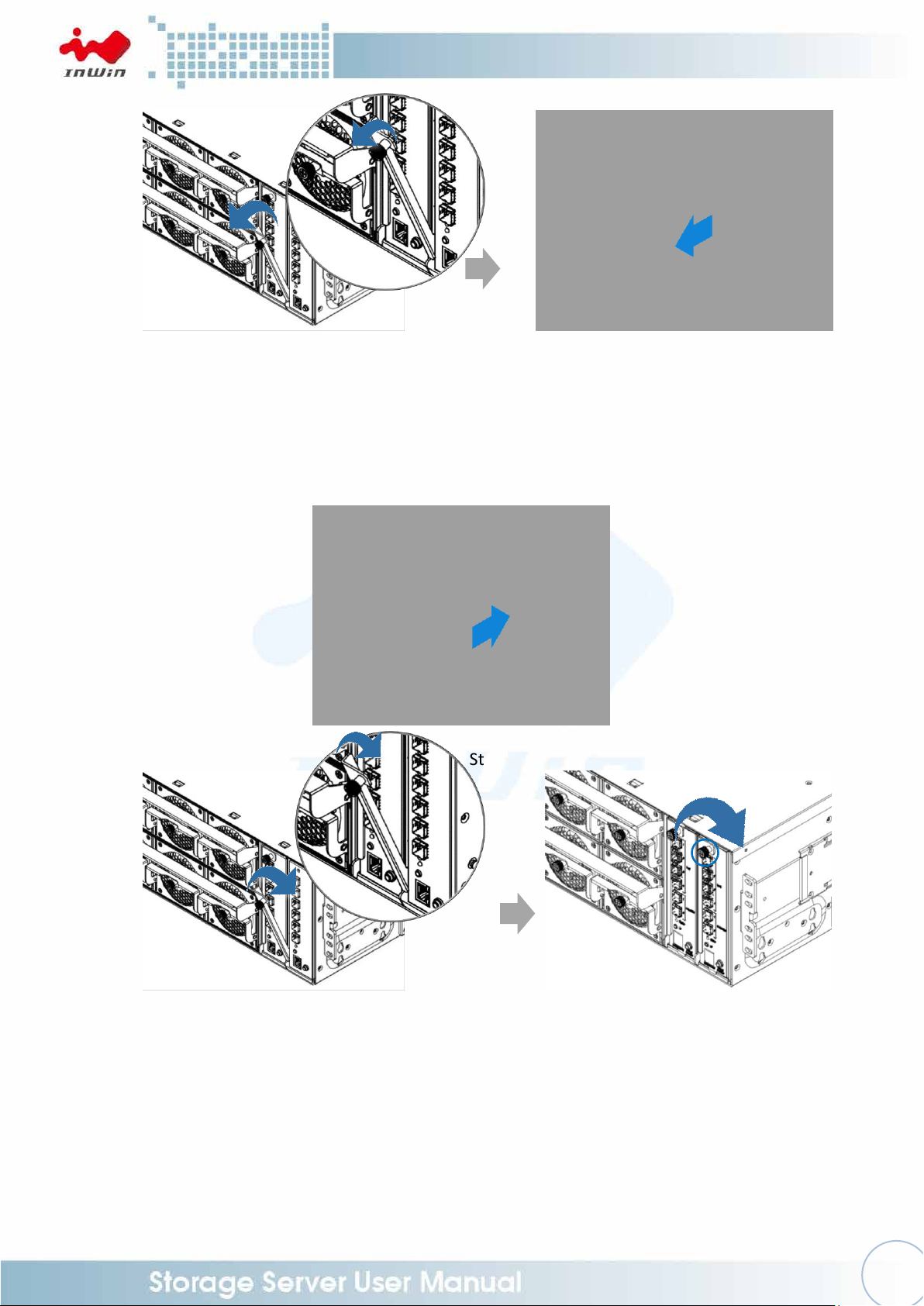
2.4.1 Removing the Host Expander Module
Step 1: Loosen the thumbscrew of the host expander module.
Step 2: Rotate the expander module lever outward.
Step 3: Pull out the expander module.
Step 1
Page 18
15
Step 2
Step 3
Pull
Push
Step 2 Step 3
2.4.2 Installing the Host Expander Module
Step 1: Push the expander module into the cage until it clicks back to the original
location.
Step 2: Rotate the lever back into position.
Step 3: Tighten the thumbscrew.
Step 1
2.4.3 Removing the Disk Expander Module
NOTE: Do not leave the HDD drawer open for more than 1 minute to prevent
overheating.
Step 1: Open the HDD drawer. (Please refer to 2.1.1)
Step 2: Loosen the thumbscrews and side screws of the enclosure, then remove
the cable management cover.
Step 3: Remove the cable from the disk expander module.
Page 19

16
Step 2
Step 3
Step 4
Step 5
Unplug
the Cables
Pull
Step 4: Loosen the thumbscrew of the module.
Step 5: Rotate the disk expander module handle outward.
Step 6: Pull out the disk expander module.
Step 6
Page 20

17
Step 2
Step 3
Push
Connects
the Cables
Push
Step 1
2.4.4 Installing the Disk Expander Module
NOTE: Do not leave the HDD drawer open for more than 1 minute to prevent
overheating.
Step 1: Place the disk expander module into the cage until it clicks.
Step 2: Align the thumbscrew into position and tighten the thumbscrew.
Step 3: Connect the cable to the disk expander module.
Step 4: Push the cable management cover back to original position.
Tighten the thumbscrews and side screws of the enclosure.
Step 5: Close the HDD drawer. (Please refer to 2.1.2)
Step 4
Page 21

18
Install the Inner Rails of Fixed Rail Blade to the Rack
Front
Rear
Rear
Front
2.5 Rail Installation
The IW-RJ448-05 JBOD is a high density 4U rackmount storage model, which supports
EIA-RS310D standard cabinets and chassis racks. InWin provides standard fixed rail
blades for mounting the RJ448-05 JBOD chassis to cabinets.
2.5.1 The Type of Rail Kit
Please follow the instructions to install the rails on the cabinet or chassis rack
according to the rail type you ordered.
2.5.2 Fixed Rail Blade
2.5.2.1 Installing the Fixed Rail Blade to the Rack
Step 1: Prepare the rack posts with square nuts (yellow squares).
Step 2: Adjust the fixed rail blade to match the rack depth. Secure with
M4x6L screws (yellow circles).
Place the fixed rail blade to the rack and align the post holes on the
rack. Secure with M5x10L screws.
2.5.2.2 Insert the Enclosure to the Rack
Step 1: Place the removable handle rivets into the holes and move
upward until it locks. Secure with the thumbscrews.
Page 22

19
NOTE: Heavy! Handle with Care!
Use and secure the removable handle rivets before transporting.
At least two people are required for the following operation:
Front
Rear
Rear
Front
Step 2: Place the unit into the rack carefully.
Align the fixed rail blade to the rail bracket and push the chassis
towards the rear of the cabinet.
Step 3: Tighten the front ears (circled in red) to the front of the rack with
four screws.
Step 1
Page 23

20
Front
Rear
Rear
Front
Front
Rear
Rear
Front
Step 2
Step 3
Page 24

21
Location
Description
JS1-JS4
(HOST) External Uplink
MINI SAS HD Connector
JS5-JS6
(Expansion)External Downlink
MINI SAS HD Connector
LED1-LED6
PHY LINK LED
LED7
Status LED
CN1
Programming (Factory Only)
SW1
ID SW/LED
SW2
System Reset (Factory Only)
SW3
Flash Burn-In Test (Factory Only)
CON2
Management LAN Port
JD1
EXP Smart Console Mode
JD2
EXP Debug Console Mode
JD4
System Debug Console Mode
EFN1
Expander Fan
BT2
RTC Battery
3 Expander Board Introduction (Host & Disk)
3.1 Expander Board (Host)
Page 25

22
Location
Description
JD1
Programming (Factory Only)
JD2
Console Debug Mode
JD3
Console Smart Mode
JC1
MB Fan Control
JC2
PMBUS
JC3
Front Panel Signal Connector
EFN1
Expander Fan Connector
LED11/12/13
(LED11-13) JS1-JS3 PHY LED
LED01
Expander Heartbeat LED
JS1-JS3
JS1-JS2: Internal Mini-SAS HD Uplink
JS3: Internal Mini-SAS HD Downlink
JM1
Power Mode Select
3.2 Expander Board (Disk)
Page 26

23
4 User Interface Introduction
4.1 Overview
InWin’s JBOD System is a high performance, reliable storage system with sensors to
monitor system health.
We provide state-of-the-art management functionality for users to monitor and manage
JBOD systems efficiently and flexibly.
Users can manage JBOD systems through serial port and/or Ethernet according to the
system configuration on the system. We support a variety of network protocols for
network management including Telnet, SSH, Web-GUI, SNMP and SMTP. We also
support active system alert functions by sending information to email addresses
specified in the system, so the users can be informed of any system changes in a timely
manner.
This users’ manual is for all series of InWin JBOD systems including RJ-212, RJ-224, RJ316, RJ-424, RJ-448, RJ-460 and RJ-472. It provides the information and instructions of
frequently used functions. Please refer to the table of contents to find the topics you are
interested in.
InWin High Density 4U JBOD system shares the same expander user interface. Please
use the following image of RJ-472-05 as an example. The actual product's model will
appear when the program is executed.
4.2 Key Features
•Reliable High Data Rate Support (up to 12Gbps)
SAS 12Gbps support and SATA3 6Gbps support to provide a reliable high-performance
data rate.
•Dual Expanders Support
System can accommodate dual expanders to support data redundancy capability.
•Power Redundancy
System can accommodate 2 sets of power modules as redundancy. Either power
module could work independently while the peer is out of order or not installed.
•Hot-swappable Power Module
The PSUs are hot-swappable. No need to shut down the system for PSU replacement
when required.
•Hot-swappable Fan Modules
The fan modules are hot-swappable. No need to shut down the system for fan module
replacement when required.
•Faulty System Alarm
The Faulty System red LED indicator on the front panel illuminates along with a
beeping sound while there is faulty part(s) in the system.
Page 27

24
The beeping sound can be muted by pressing the mute button on the front or rear
panel.
•Hot-swappable HDDs
The HDDs are hot-swappable. No need to shut down the system for HDD installation
and/or replacement when needed.
•Smart Fan Control
The fan modules possess a smart control feature set by the firmware to provide seven
levels of speed RPM according to the detected system temperature.
•Zoning
This system support feature divides disk drives into two or more different groups
depending on the system preference. Each group can own users-configurable number
of HDDs independently. This feature enables single JBOD to serve multiple hosts.
•Cascading
There are cascading ports on the Expander for cascading another JBOD system to
expand disk space when more space is required.
4.3 Software Management
4.3.1 System Management Structure
InWin’s JBOD Systems supports an out-of-band Network Management feature,
which enables a rich set of protocols and a flexible way for SAS Expander
management anytime from anywhere.
4.3.1.1 Ethernet Management
The Bridge Expander is equipped with a network management port
allowing users to manage JBOD systems from a remote location.
With a proper IP address setting, users can manage the system through
Telnet, SSH, Web-GUI and SNMP remotely.
Page 28

25
The rich set of network protocols are leveraged for flexible remote
management. The supported protocols including Telnet, SSH, Web-GUI,
SNMP and SMTP enables various ways to manage the system.
Please be sure the IP address of the system is correctly configured to
enable network access. Our system’s supports are Static IP address or
DHCP dynamic IP address as per users’ configuration.
4.3.1.2 Serial Port Management
A 3.5mm audio jack serial port (RS-232) on the Expander module enables
users to manage the system through terminal console applications such
as Tera Term, Putty, etc. Users need to prepare a DB9 RS-232 adapter on
host and connect to a serial cable shipped along with the system to gain
access to the serial port management. Use CLI commands to manage the
system through serial console.
4.3.2 Serial Port Management
The RS-232 port on the Expander module provides a serial connection for users to
manage the JBOD system with terminal application such as Tera Term, Hyper
Term…etc. To manage the JBOD system through the serial port, configure the
terminal console as per the settings below to connect it.
Baud Rate : 115200
Data : 8 bit
Parity : None
Stop Bit : 1 bit
Flow Control : None
Page 29

26
4.3.2.1 CLI Commands
Some useful CLI commands are listed below
■ Network Management Layer
The “/mgmt.s#” prompts in the Console Terminal, which means the
system is now in the network management level. Under this level, users
can manage the network setting such as configuring the IP address and
enabling/disabling services.
The “list” command displays all the Ethernet layer commands the system
supports.
The “help” command lists the description of the commands.
Type command without argument to display the current status.
Type command with “?” to display the usage of the command.
Type command with argument to configure the setting of the command.
Page 30

27
Any changes that have been made only available until system reboot. Please be
sure to type ‘save’ command to store the configuration so the changes will be
kept for next system boot.
Note:
■ Expander Management Layer
The “cd expander0” or “console 0” changes the directory for bridge
expander management. In this layer, users can manage SAS Expander
settings “cd ..” or “CTRL-X” to change the directory back to the upper
layer. It’s typically used for jumping back to the network management
layer from expander management layer.
The “?” or “help” displays the CLI commands for the SAS Expander.
Type “command” to display the current status of the command.
Page 31

28
Please jump back to “mgmt.s” layer by typing “cd ..” or “CTRL X” every time
before you can jump to another expander management layer.
Type “? <command>” to display usage of the command.
As the design, there are three internal expanders inside the chassis
expanded from the bridge expander. Users can also get into the internal
expander management when required.
Type “cd expander1” or “console 1” to manage 1st expander.
Type “cd expander2” or “console 2” to manage 2nd expander.
Type “cd expander3” or “console 3” to manage 3rd expander.
Note:
4.3.3 Network Management
The Ethernet port on Expander module is to provide Network Management in
various protocols such as Telnet, SSH, Web-GUI and SNMP. It also provides an
email notification while an alarm is in effect by properly configuring the SMTP
information.
The default settings of the network information are as listed below:
IP Address : 192.168.100.1 (Static IP Address)
Subnet Mask : 255.255.255.0
Gateway : 192.168.100.254
Username : admin
Password : default
* Please be sure the system IP network is reachable by the management host.
* Users can make changes of the settings to meet the network environment.
* For security reasons, we strongly recommend users to change the password
immediately before the system is put online.
Page 32

29
The factory default IP address is static address 192.168.100.1. If there is a DHCP server
in the IP network, users can simply change the IP address on web GUI or through serial
console.
In serial console, type “dhcp 1” in “mgmt.s” layer to enable dynamic IP address for the
system. Type “save” so the setting is kept for the next system boot.
Note:
4.3.3.1 Telnet
■ The Telnet service is enabled by default. It shares the same level of CLI
commands as it is through the serial console terminal.
Users can disable the Telnet support on web GUI or with CLI commands if
there are security concerns.
In CLI, in “mgmt.s” layer type “service telnet 0” to disable telnet service.
■ The difference compared with serial console is that Telnet sessions
require a Credential (Username and Password) to gain access to it.
Refer to the above session for the default credential information.
■ Below is a reference capture of a tenet session.
4.3.3.2 SSH
■ The SSH service is enabled by default. It provides the same level of CLI
commands as it is through serial console or Telnet session.
■ SSH provides a secure connection between host and the JBOD system. It
is enabled by default on most Linux OSes. There are some freeware SSH
tools for Windows such as Putty, Tera Term, …etc.
■ Below is the Tera Term example to establish the SSH session.
Page 33

30
Page 34

31
4.3.3.3 Web-GUI
■ The Web-GUI is the easiest way to manage the JBOD system. It is enabled
by default on this system.
■ Users can simply open the web browser and give the JBOD management
IP address in the URL address field to start managing.
Page 35

32
Login Page
Version Page
Page 36

33
inwin-jnm.mib
System Page.
4.3.3.4 SNMP
■ The SNMP is a popular network device management protocol that is
widely used by IT people to manage mass amounts of systems, devices
and equipment which are embedded with a SNMP agent.
■ The InWin JBOD system’s management module is implemented by a
SNMP agent with v1 and v2c support.
■ Users need to configure the same read and write community string in the
JBOD system as the SNMP manager so the system can be managed by the
SNMP Manager.
■ An InWin proprietary MIB, which defines system information, is required
for the SNMP Manager so the OID is accessible.
Below is the proprietary MIB file:
■ SNMP Settings on the System
Users can change the SNMP settings through CLI and Web-GUI.
‧Check and configure via CLI
‧Check and configure via Web
Page 37

34
■ SNMP Manager
Any SNMP Managers can be used to manage the system by properly
configuring the system settings including IP address, read community
string and write community string to match the settings in the system.
Compiling the InWin JBOD MIB file to the SNMP manager is necessary.
Below is an example to browse the system MIB with a free SNMP
Manager tool.
4.3.4 Version Information
Users can check the system hardware and firmware version through various ways
with CLI commands, Web GUI and SNMP.
Page 38

35
4.3.4.1 CLI (UART, Telnet and SSH)
■Type the “version” command on “mgmt.s” Layer to display all the version
information including Ethernet firmware version, Expander firmware
version and MFG CFG file version.
4.3.4.2 Web-GUI
■ Type system IP address on Web Browser URL address field to gain access to the
system. After logging in, click “Version” on the left pane to view the system
version information on the right pane. Scroll down to view all information if the
display is out of page.
4.3.5 System Status
The System Status is to display the status of the system sensors including
temperature, voltage, fan speed and power supply. All the SAS Expander modules
are equipped with sensors to monitor system health and control environmental
cooling systems accordingly.
Page 39

36
4.3.5.1 CLI (UART, Telnet and SSH)
■ Type “encl sensor” command in “mgmt.s/expander0” layer to display the
System sensors’ readings and their status.
■ Please note that the Expander temperature sensors “Exp Die” is the
silicon core temperature and the temperature sensors “BPx-Sensor x” are
on the backplanes.
■ There are mechanisms communicating between primary and secondary
domain expander modules so the peer side module sensors information
can be exposed at the same screen.
4.3.5.2 Web-GUI
■ Type the system IP address on the web browser URL filed to gain access to
the system. After logging in, click “System” on the left panel to view the
system status information on the right panel. Scroll down to view all
information if the display is out of page.
Page 40

37
4.3.6 Network Settings
The Network settings is for configuring system network information such as
DHCP/Static IP Address selection, Network Services, Mail configuration and SNMP
configuration.
4.3.6.1 CLI (UART, Telnet and SSH with Ethernet Board)
4.3.6.2 Web-GUI
■ There are a couple network setting commands on ”mgmt.s” layer such as
“ipaddr”, “gateway”, “netmask”, …etc. to view and configure the settings
respectively.
■ Please be sure to apply the “save” command so the settings are saved for the
next system reboot.
■ Type the system IP address on the web browser URL field to gain access to the
system. After logging in, click the “Network” button on the left panel to view the
network information on the right panel. Scroll down to view all information if
the display is out of page.
Page 41

38
4.3.7 Disk Information
The disk information is to show the disk drives’ status on the system, including Bay
id, Phy id, SAS Address, Link speed and current status.
4.3.7.1 CLI (UART, Telnet and SSH)
■ Type the “phyinfox -s” command on “mgmt.s/expander0” layer to display
the system hard disk drives’ status on the system.
Page 42

39
4.3.7.2 Web-GUI
■ Type the system IP address on the web browser URL field to gain access to
the system. After logging in, click the “Disk” button on the left panel to
view the disk drives information on the right panel. Scroll down to view all
information if the display is out of page.
4.3.8 Zone Setting
The Zoning feature supports the function to divide disk arrays into multiple groups.
Once the zoning feature is enabled, the specific-wide port is hard-coded and
designed to join the specific group as the access port of the specific group.
RJ-212, RJ-316, RJ-224 support 2-group zoning.
RJ-448 supports up to 4-group zoning – mode 2 and 4
RJ-472 supports up to 6-group zoning – mode 2, mode 3 and mode 4.
RJ-460 does not support zoning.
Note: Zoning Mode Definition
Mode 2: Configure JBOD system disks into 2 groups
Mode 3: Configure JBOD system disks into 3 groups
Mode 4: Configure JBOD system disks into 4 groups
Mode 6: Configure JBOD system disks into 6 groups
4.3.8.1 CLI
■ For RJ-472-05 and RJ-448-05 systems,
Type “ucfg.zone” command in “mgmt.s/expander0” layer to show the
zoning status.
Type “ucfg.zone + n” command in “mgmt.s/expander0” layer to enable
the zoning setting where n= 2, 3, 4 or 6.
Type “ucfg.zone - ” command in “mgmt.s/expander0” layer to disable the
zoning setting.
Please refer to below the capture for details of the configuration.
Page 43

40
■ For RJ-212-03, RJ-316-03 and RJ-424-03 systems,
Type “c.zone” command in “mgmt.s/primary” and “mgmt/secondary”
layer to show the zoning status.
Type “c.zone enable” to enable zoning feature.
Type “c.zone disable” to disable zoning feature.
Please refer to below the capture for details.
Page 44

41
Zoning configuration with CLI in serial console or Telnet session requires a system reboot
to take effect.
In Web-GUI, Expanders would be reset when applied.
Zoning configuration needs to be set on both domains manually to make them work
consistently.
Note:
4.3.8.2 Web-GUI
Web GUI provide a more user friendly way for configuring and checking
zoning for JBOD systems.
■ For RJ-472-05 and RJ-448-05
Type the system IP address on the web browser URL field to gain access
to the system. After logging in, click the “Zone” button on the left panel to
view and configure the zoning setting of the system on the right panel of
the page.
Select zoning mode on the right panel of Zone page by clicking on the
radio button. After configuration is selected, click “Apply” button to reset
the Expanders to take effect.
Page 45

42
■ For RJ-212, RJ-316, RJ-224 and RJ-424
Type the system IP address on the web browser URL field to gain access
to the system. After logging in, click the “Zone” button on the left panel to
view and configure the zoning setting of the system on the right panel of
the page.
Select zoning mode on the right panel of Zone page by clicking on the
radio button. After configuration is selected, click “Apply” button to reset
the Expanders to take effect.
These JBOD systems support flexible zoning configuration meaning that
each disk is allowed to configure to either Group1 or Group2.
4.3.9 Firmware Upgrade
The firmware upgrade function provides a way to update system firmware when
necessary.
Page 46

43
Be careful NOT to power off the system when conducting system firmware upgrade.
Power loss during firmware upgrade would somehow crash system firmware.
In case firmware crash occurs, call help from technical support.
There are 3 firmware for the InWin JBOD system:
1. Network Management Firmware
2. SAS Expander Firmware
3. SAS Expander MFG CFG file
There are a couple of ways to upgrade the system firmware according to the HW
configurations. Please note that the upgraded firmware won’t take effect until a
system reboot
Note:
4.3.9.1 CLI (Telnet or SSH)
Users are able to upgrade management firmware, SAS Expander firmware
and MFG CFG file through TFTP or Xmodem when using CLI commands.
Below the examples are with TFTP server.
All sorts of firmware upgrades going through TFTP would be intelligently
upgraded to the right hardware. More conveniently, all Expanders
(including Bridge Expander and internal expanders, they are sharing the
same firmware and MFG file) can be upgraded at the same time when
upgrade command is applied and committed.
To upgrade through TFTP, open a TFTP server on your console host and
specify the path in TFTP server to the directory where the firmware is
stored. Please be sure the TFTP server is reachable to the JBOD system.
Page 47

44
■ Management Firmware upgrade
Type “upgrade <tftp_server_ip> <filename>” command to start
Management Firmware upgrade.
■ SAS Expander Firmware
It’s the same as for Management firmware by using the Expander
Firmware filename instead in command.
“upgrade <tftp_server_ip> <filename>”
Page 48

45
■ SAS Expander MFG CFG file
Same as Management firmware by using the Expander MFG CFG file
filename in command.
“upgrade <tftp_server_ip> <filename>”
Page 49

46
4.3.9.2 Web-GUI
■ Upgrade system firmware through Web-GUI is much easier than other
ways. Just simply select the firmware by file browser and click ‘Apply’ to
start.
All the firmware including Network Management firmware, SAS Expander
firmware and MFG CFG file apply the same way to upgrade.
After system upgrade, be sure to reboot system to take effect the new
firmware which has been upgraded to the hardware.
■ Click the “Tool” button on the left panel and scroll down to “Software
Upgrade,” the session is on the right panel.
Click the “Choose File” button to select the firmware being upgraded
from file browser and click “Open” to commit.
The firmware can be management firmware, SAS Expander firmware or
SAS Expander MFG CFG file. The system would intelligently detect the
firmware type and upgrade to the right hardware.
Page 50

47
Click the “Upgrade” button to start the firmware upgrade.
Web would direct to a page telling the firmware is upgrading.
After upgrade is done, Web will direct to the Login page.
Page 51

48
A system reboot is require to take effect.
4.3.10 Web Console
Web console provides an easy way for users to apply CLI commands to a specific
SAS Expander without needing a console terminal.
4.3.10.1 Utilize Web Console
■ Login into Web-GUI then click “Console” on the left panel.
Then, on the right panel, select the SAS expander that you would like to
apply the command to and fill the command to the rightest square.
Click “RUN” to apply commit the command to expander.
The output of the command would appear on the lower square.
To clear the console output, click the “Clear” button.
Page 52

49
4.3.11 Advanced Configuration
There are some other advanced configurations that the users might want to
configure to the non-factory-default settings.
Warning:
Changing factory default setting is not encouraged. Please be sure you have
consult our technical staffs before making these changes.
Be cautious to the risks of the changes you have made.
4.3.11.1 Cooling Policy
■ The factory default system cooling mode is set to regular cooling mode
which might cover most system thermal requirement cases. However, the
JOBD systems designed to allow users configuring to other modes for
some applications.
■ Uers can then configure the system cooling mode in console CLI.
For RJ-472-05 and RJ-448-05:
Command “ucfg cool” under “mgmt.s\console 0” layer to show the
current cooling mode.
Command “ucfg” under “mgmt.s\console 0” to show cooling mode
allowed to set.
Command “ucfg cool <CoolMode> under “mgmt.s\console 0” layer to
change cooling mode. eg. “ucfg cool ac” will turn cooling mode into
aggressive mode.
Be sure to configure the same on both domains and reset system to take
effect the settings.
For RJ-212, RJ-316, RJ-224 and RJ-424:
Command “? c.syscfg” under “mgmt.s\primary” or “mgmt.s\secondary”
layer to show the cooling mode allowed to set.
Page 53

50
Command “c.syscfg cool <CoolMode>” under “mgmt.s\primary” or
“mgmt.s\secondary” layer to set the cooling mode. Eg. “c.syscfg cool ac”
to turn into aggressive mode.
Be sure to configure the same on both domain and reboot system to take
effect.
4.3.11.2 EDFB Configuration
■ EDFB is a feature of Avago expander chip to boost the IO performance for
the higher speed device to lower speed device by store-and-forward
technology. The EDFB mode is default disabled for RJ-472-05 and RJ-44805 JBOD systems and default enabled for RJ-212, RJ-316, RJ-224 and RJ424 JBOD systems.
■ Users is allowed to enable or disable the feature in console CLI when
required.
Note: as per Avago, EDFB has disk compatibility risk that might casue
some SATA HDDs not detected once enabled. So, please disable the
feature in case the disk compatibility issue is encountered.
For RJ-472-05 and RJ-448-05:
Command “ucfg” under “mgmt.s\console 0” layer to show the command
usage.
Command “ucfg edfb” under “mgmt.s\console 0” layer to show the
current EDFB status.
Command “ucfg edfb <EefbMode>” “mgmt.s\console 0” layer to enable
EDFB mode. Eg. “ucfg edfb en1” to enable EDFB mode for SATA drives.
Please be sure to reboot system to take effect after configuration.
Page 54

51
For RJ-212, RJ-316, RJ-224 and RJ424:
Command “? c.syscfg” under “mgmt.s\primary” or “mgmt.s\secondary”
layer to show the command usage.
Command “c.syscfg <EdfbMode>” under “mgmt.s\primary” or
“mgmt.s\secondary” layer to enable or disable EDFB mode.
Eg. “c.syscfg edfb dis” to disable EDFB mode. Please be sure to reboot
system to take effect after configuration.
Page 55

52
Function
Command
cd
changes control path to management board or expander control path
date
display or set current date/time
dhcp
display or set DHCP client
dns
display or set DNS server
gateway
display or set router (example: 192.168.100.254)
ipaddr
display or set Ethernet IP address (example: 192.168.100.100)
list
list path commands or control path
mail
display or set send mail parameters
netmask
display or set Ethernet IP netmask (default: 255.255.255.0)
passwd
change password
reboot
reboot management board
save
save configuration to NVRAM
service
display or set service (Telnet/SSH/WEB/SNMP)
upgrade
upgrade management board or expander software
useradd
add new user account
userdel
delete a user account
userlist
list user account
version
display management board's information
Function
Command
Enclosure Info
encl [Info-Type]
- Info-Type:
rev : Show H/W & S/W revision
sensor : Show enclosure sensor state
pd : Show disk phy state
pmon : phy signal monitoring
(Omit Info-Type to dump all)
cmfg : Show MFG embeded in FW
Zone Configuration
ucfg.zone < [state] | enable | disable >
When enabled:
-- Disks are divided into 2 zones
-- Each BRC exposes disks in one zone
(Primary: Zone #1 ; Secondary: Zone #2)
4.4 Appendix A
Management Firmware CLI Commands
4.5 Appendix B
SAS Expander Firmware Useful CLI Commands
Page 56

53
Function
Command
Console Select
con [ 0 .. 2 | 'n' | 'p' | '?' ]
'n', 'p': switch to next/previous console,
'?' : display current console ID
(Omit parameter to select 1st console)
Show/Set the current
date [ set <newdate(*)> |
Date and Time
send [<SasAddrHi(H)> <SasAddrLow(H)>] |
recv [<SasAddrHi(H)> <SasAddrLow(H)>] ]
- no arguments, output local expander date/time and
uptime
- 'set <newdate(*)>' Set local expander date/time using
format for <newdate> of YYYYMMDDHHMMSS
- 'send [sas_addr]' If sas_addr set then set the remote
expander's clock using the local expander's current clock
value. If sas_addr not specified then set clock for all
expanders in the domain.
- 'recv [sas_addr]' If sas_addr set then fetch the remote
expander's current clock and output the result. If
sas_addr not specified then get and output the current
clock for all expanders in the domain.
Reset the Expander
reset [watchdog]
Display phy info.
phyinfox [ -i [(1 .. NumBpc] ] | -s
-i : show phy info of BPC expander
-s : show SES Array Device info of CSE BRC
(bridge console only)
Configuration Update
mfgdl
Download and Update MFG configuration.
(feed it with 'MFG image file')
Firmware Update
fwdl
Download and update firmware
Display info for all phys
phyinfo [help|edfb|power|cable]
[up|<PhyNum(D)>]
- no arguments displays default output
- 'help' displays detailed help information
- 'edfb' subcommand displays EDFB info
- 'power' subcommand displays power mgmt info
- 'up' filters to display connected phys only
- 'cable' subcommand displays cable mgmt info
- <PhyNum> is a valid phy index and filters the output to
display info about that phy
Page 57

54
Function
Command
Display or Reset All
counters [config|event|reset]
- no arguments displays phy error counters and generic
broadcast counters
phy counters
- 'config' subcommand displays phy event configuration
- 'event' subcommand displays phy event counters
- 'reset' subcommand resets all phy counters
Display Expander
sasaddr [-d]
SAS Address
('-d': also show virtural ports address)
Show POST info
showpost
Show MFG Revision
showmfg
Show firmware revision
rev
5 Compatibility Lists
To reach the best performance and avoid system failure, InWin strongly recommends users to
choose the components from InWin’s compatibility list. All the components are tested in
InWin’s lab, and assured the components are complementary with InWin’s chassis.
You can download the latest updated device compatibility list from InWin’s website:
https://www.in-win.com/en/ipc-server
6 Technical Support
If you need help with installation or troubleshooting, you can contact your local InWin partner,
or send an e-mail to InWin’s local contacts for technical assistance.
 Loading...