

Page 1
- 0 -
IW-RJ224-03
User’s Manual
Page 2
- 1 -
Table of Content
PREFACE
P.4
SAFETY INFORMATION
P.5
SPECIFICATIONS
P.6
1 Product Introduction
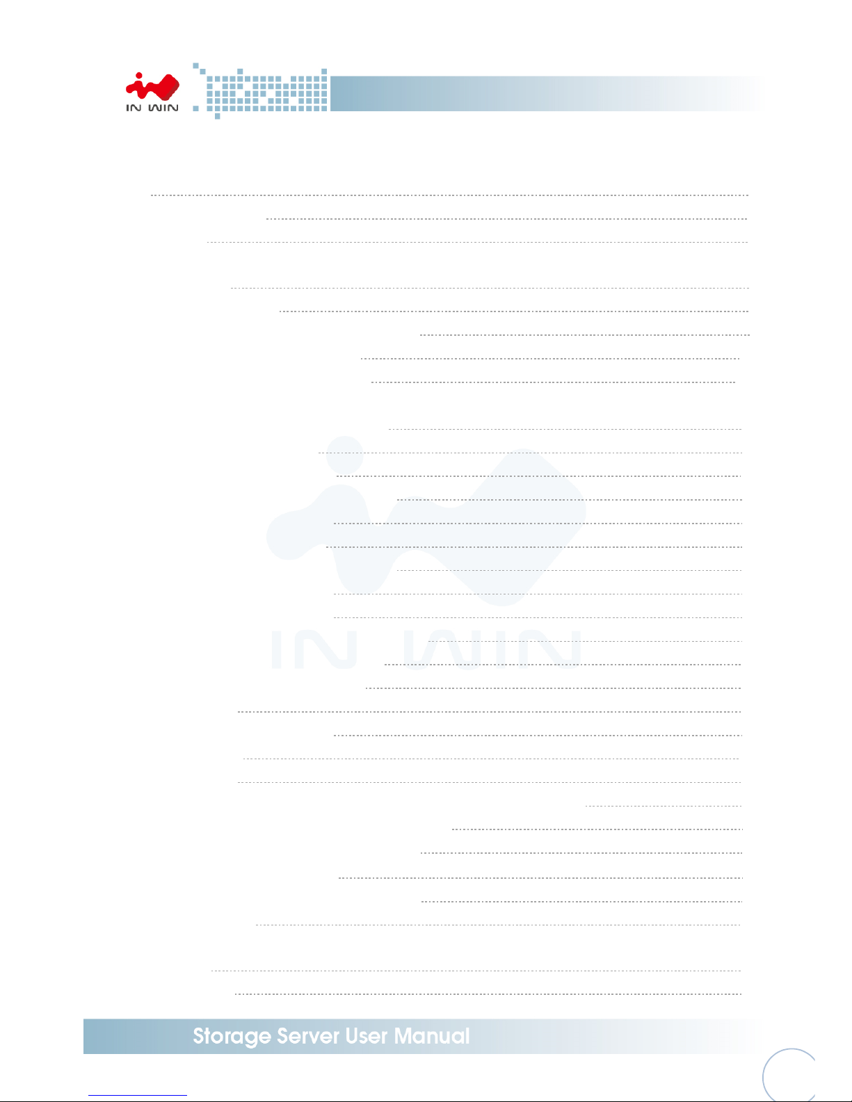
1.1 Box Content P.7
1.2 General Information P.8
1.2.1 Front Panel Controls and Indicators P.9
1.2.2 Rear Panel Configuration P.10
1.2.2.1 Expander Configuration P. 1 0
2 Hardware Installation
2.1 Removing and Installing a Hard Drive P.11
2.1.1 Installing a Hard Drive P.11
2.1.2 Removing a Hard Drive P.11
2.2 Removing and Installing a Fan Module P.12
2.2.1 Removing a Fan Module P.12
2.2.2 Installing a Fan Module P.13
2.3 Removing and Installing a PSU Module P.13
2.3.1 Removing a PSU Module P.13
2.3.2 Installing a PSU Module P.14
2.4 Removing and Installing a Expander Module P.14
2.4.1 Removing a Expander Module P.14
2.4.2 Installing a Expander Module P.15
2.5 Installing Rail P.15
2.5.1 Identifying the slide Rail P.15
2.5.2 Fixed Rail P.16
2.5.3 Slide Rail P.16
2.5.3.1 Take out the inner rail and slide the intermediate rail back P.16
2.5.3.2 Mount the rail bracket to the cabinet P.17
2.5.3.3 Insert the chassis to the cabinet P.18
3 Expander Board Introduction
P.19
4 Ethernet Management Card Introduction
P.20
5 Compatibility Lists
P.21
6 User Interface Introduction
6.1 Overview P.21
6.2 Key Features P.21
Page 3

- 2 -
6.3 Software Management P.22
6.3.1 System Management Structure P.22
6.3.1.1 With Ethernet Management P.22
6.3.1.2 Without Ethernet Management P.23
6.3.1.3 Network Protocols Support P.24
6.3.1.4 Operation Modes P.24
6.3.2 Serial Port Management P.27
6.3.2.1 CLI P.28
6.3.2.1.1 Scenario 1: Expander with Ethernet board P.28
6.3.2.1.2 Scenario 2: Expander w/o Ethernet board P.31
6.3.3 Network Management P.32
6.3.3.1 Telnet P.33
6.3.3.2 SSH P.33
6.3.3.3 Web-GUI P.36
6.3.3.4 SNMP P.38
6.3.4 Version Information P.41
6.3.4.1 CLI (UART without Ethernet Board) P.41
6.3.4.2 CLI (UART, Telnet and SSH with Ethernet Board) P.42
6.3.4.3 Web-GUI P.44
6.3.5 System Status P.44
6.3.5.1 CLI (UART without Ethernet Board) P.44
6.3.5.2 CLI (UART, Telnet and SSH with Ethernet Board) P.46
6.3.5.3 Web-GUI P.47
6.3.6 Network Settings P.48
6.3.6.1 CLI (UART, Telnet and SSH with Ethernet Board) P.48
6.3.6.2 Web-GUI P.49
6.3.7 Disk Information P.50
6.3.7.1 CLI (UART without Ethernet Board) P.50
6.3.7.2 CLI (UART, Telnet and SSH with Ethernet Board) P.50
6.3.7.3 Web-GUI P.52
6.3.8 Zone Setting P.53
6.3.8.1 CLI (UART without Ethernet Board) P.53
6.3.8.2 CLI(UART, Telnet and SSH with Ethernet Board) P.53
6.3.8.3 Web-GUI P.52
6.3.9 Firmware Upgrade P.56
6.3.9.1 CLI (UART without Ethernet Board) P.56
6.3.9.2 CLI (Telnet or SSH with Ethernet board) P.60
6.3.9.3 Web-GUI (with Ethernet board) P.64
Page 4

- 3 -
6.3.10 Firmware Upgrade P.67
6.3.10.1 CLI (UART without Ethernet Board) P.67
6.3.10.2 CLI (UART, Telnet, SSH with Ethernet Board) P.70
6.3.10.3 Web-GUI (With Ethernet Board) P.71
7 Q&A
P.72
8 Technical Support
P.75
Page 5

- 4 -
PREFACE
Thank you for choosing In Win IW-RJ224-03. This manual is written for system technicians who are
responsible for installation, troubleshooting, managing, and repairing this server chassis. This
document provides the overview of all the features of the chassis, a list of accessories or other
components you may need to finish the installation, troubleshooting methods, and instructions of
adding and removing components on the In Win IW-RJ224-03. For the latest version of this manual,
you may visit In Win’s server website to download the latest updated version.
SAFETY INFORMATION
To ensure safe and smooth operation of your In Win IW-RJ224-03, it is essential that you choose an
appropriate location for the system, provide an appropriate operating environment, and adequate
power for all components of the system. As you plan for installation, follow the guidelines below to
ensure that the system and its environment are safely and appropriately positioned for efficient
operation and service. Your system should be installed and serviced only by technically qualified
persons.
Environment selection: The system is designed to operate in a typical office environment. The location
should be a clean, dry, and free of airborne particles; a well-ventilated room and away from sources of
heat including direct sunlight and radiators; it should keep the sources of vibration or physical shock
away; the space should be with a properly grounded wall outlet, and with sufficient space to access the
power supply cords. The operation environment temperature should be around 0°C to 40°C (32°F to
104°F).
Heed safety instructions: Before working with In Win IPC/Storage server/ System products, we strongly
recommend you are using this guide as a reference and follow the safety instructions. The instructions
in this manual will help you ensure and maintain compliance with existing product certifications and
approvals. Follow the described, regulated components mentioned in this manual. Use of non UL
listing products or other regulatory did not approvals will make non-compliance with product
regulations in the region(s) in which the product is sold.
System power on/off: The power button DOES NOT totally turn off the system AC power. To remove
the power of system, you have to unplug the AC power cord from the outlet or system’s power supply
units. Make sure the power cord is unplugged before you open the chassis, add, or remove any
components.
Page 6

- 5 -
Hazardous conditions, devices and cables: Hazardous electrical conditions usually present on power
supply units, and communication cables. Disconnect the power cord, and any other device which
attached to the server before opening the case. Otherwise, it will raise the risk of personal injury or
equipment damage.
Electrostatic discharge (ESD) and ESD protection: In most cases, ESD damages disk drives, electronic
boards, and other parts. We recommend that you work the installation only at an ESD free space. If the
situation does not allow, perform ESD protection actions by wearing an anti-static wrist strap attached
to ground any unpainted metal surface on your server during your operation.
Installing or removing jumpers: A jumper is a short length of conductor used to close, open or bypass
part of an electronic circuit. Jumpers on In Win backplane have a small tab on top that you can pick up
with your fingertips. Grip the jumper carefully, and plug the jumper to cover the jumper pins on the
backplane. Once you need to remove the jumper, gripping the jumper, and carefully pull out without
squeezing.
CAUTION
To avoid damage and prove your safety, please notice and following the terms listed below:
1. No to populate hard drives and turn on the power before the system is settle down.
2. Tighten or loosen all the screws, please use screw driver to operate.
3. Apply the correct screws which packed in the accessories box.
4. For your safety, it requires at least two persons lift, and place the unit.
5. Before mounting the unit to the cabinet, make sure the rail is installed correctly.
6. When installing and removing any module or parts, please operate by the handles.
Page 7

- 6 -
SPECIFICATIONS
Model Name IW-RJ224-03
Standard EIA-RS310D
Dimensions (D x W x H) 520.7 x 482.6 x 87 mm (20.5" x 19" x 3.5")
Storage External: Hot Swap 2.5” x 24 SAS 12Gbps
Maximum Capacity
(per enclosure)
Cascading to 3 enclosures 72 PCS HDDs including Host Server
Power Supply
Supports
▪ Form Factor: Platinum CRPS Redundant
▪ Watt: 550W
Cooling Fan Supports Up to 8038mm x4
12G Expender module 1 or 2
Connection 2 sets of 3 x 12Gbps port
Management Smart Fan, Thermal Monitor, HDD Monitor, Voltage Monitor, Alarm warming
Host/Expansion port 3 x Mini SAS HD (SFF-8644)
SES support Supports SES-2 (SCSI Enclosure Service)
Maintenance support Maintenance and management by Ethernet(option) and RS-232
HDD Power
management
HDD sequential power on
Temperature 0ºC to 35ºC
Material
Material: SGCC
Thickness: 1.0 mm
Slide Rail
Support 20" screwless slide rail, Ball-bearing
or Fixed rail
Page 8
- 7 -
1 Product Introduction
1.1 Box Content
Page 9
- 8 -
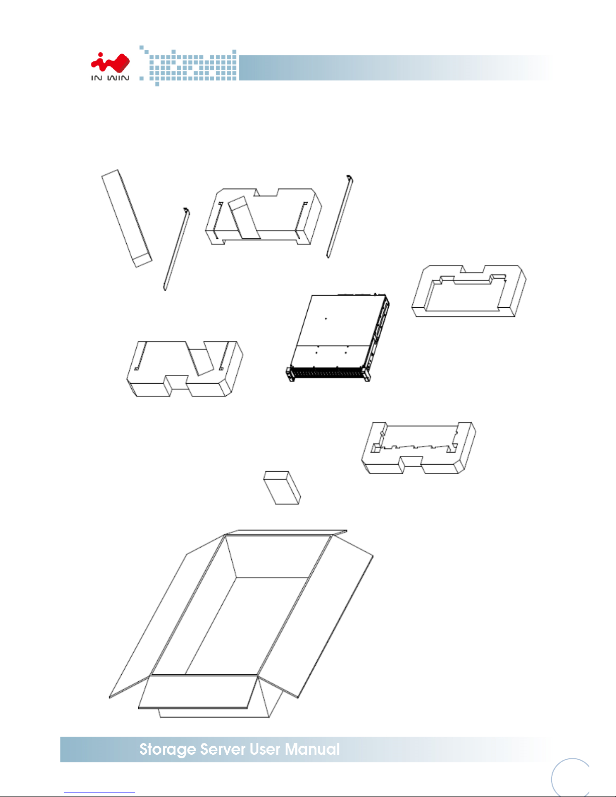
1.2 General Information
In Win IW-RJ224-03 JBOD Enclosure is a 2U rackmount storage chassis with 24 bays, dual
expander module, dual fan module, and redundant 550W power supply. IW-RJ224-03 is capable
to provide excellent performance and allowing users cascade the capacity with three more In
Win IW-RJ series JBOD enclosure.
Page 10
- 9 -
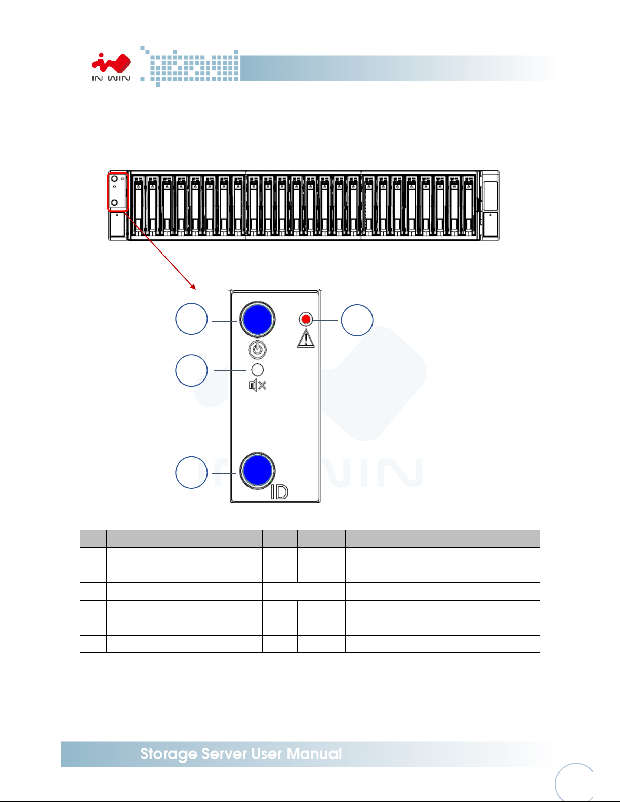
1.2.1 Front Panel
The front panel allocated on the upper left handle. The panel contains control buttons and
LED indicators.
No.
Name Color Status Description
1
Power ON/OFF Button with
LED
Blue Solid on System is powered on
N/A
Off System is not powered on
2 Mute Button N/A Press the button to turn off the beeper
3 Chassis ID Button with LED Blue Solid on Press the button to activate system
identification
4 System Fail LED Red Solid on System Fault (Beeper)
1
2
3
4
Page 11

- 10
-
1.2.2 Rear Panel Configuration
No. Name No. Name
1 Power Supply Module 1 4 Fan Module 2
2 Power Module 2 5 Secondary Expander Module
3 Fan Module 1 6 Primary Expander Module
1.2.2.1 Expander Configuration
No.
Name Color Status Description
1
Chassis ID button with LED Blue Solid on Press the button to activate system identification
2
Uplink SAS Port
N/A Host HBA/RAID card connection
3 Downlink Expander Port N/A
External cascading
4 Expander Module Status LED
Blue Blink Normal
Blue No Blinking Abnormal
5 RS-232 Port N/A Debug console connection
6 LAN
N/A
Ethernet remote monitoring (optional)
1
2
3 4
5
6
1
2
3
4 5 6
Page 12
- 11
-
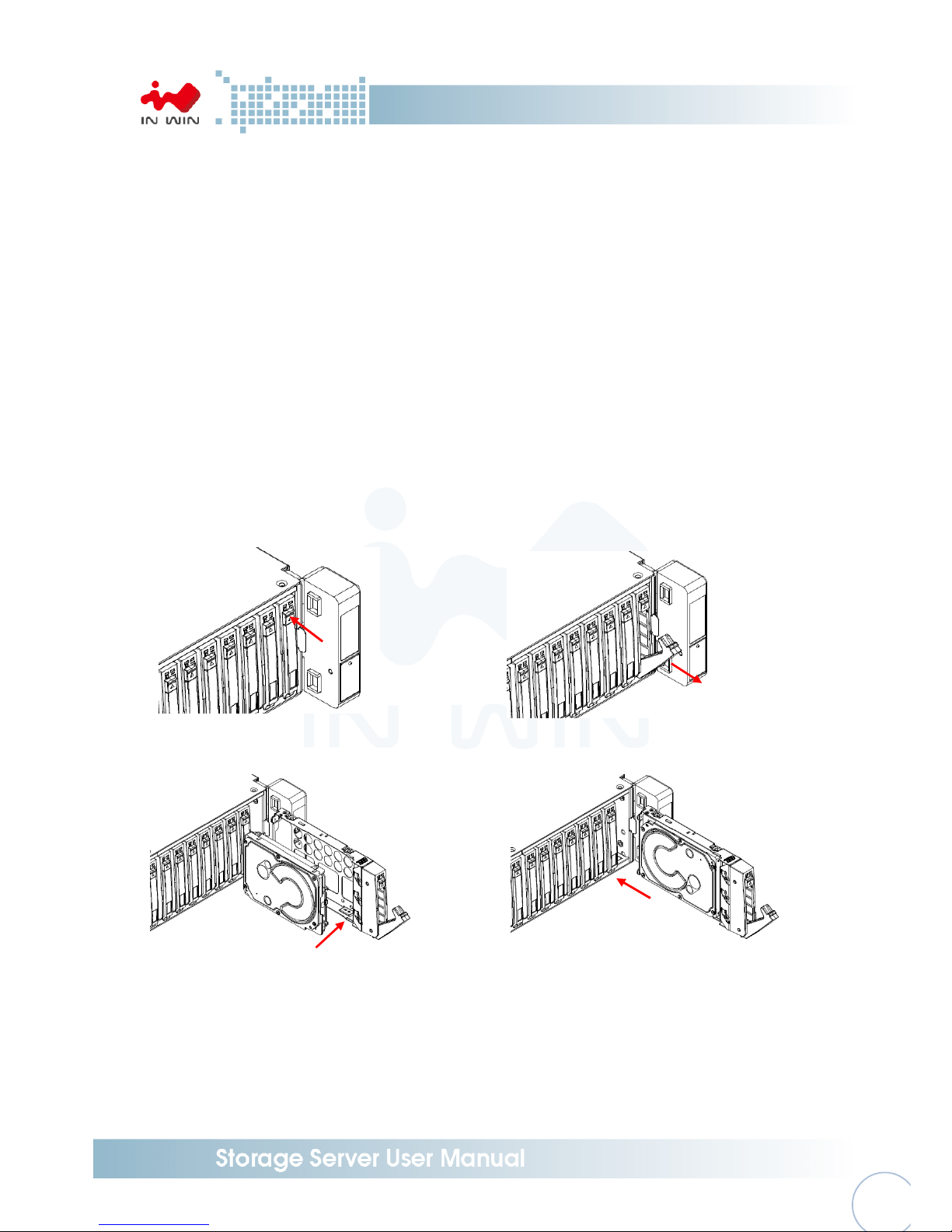
2 Hardware Installation
2.1 Removing and Installing a Hard Drive
In Win IW-RJ series JBOD is featured tray-less disk population, users do not need to use screw to
mount disks, and be able to perform quick hard disks replacement.
2.1.1 Installing a Hard Drive
Step 1: Press the release button then pull outward the handle
Step 2: Pull the handle outward to release the disk tray
Step 3: Place your hard drive on the disk tray, and make sure the connector is in rear window
Step 4: Flip over the tray, use the 4 HDD screws from the accessory box to mount the hard
drive
Step 5: Put back the disk tray with hard drive to the chassis’ terminal
Step 6: Push back the handle to the original point to complete the installation
Step 1 Step 2
Step 3 & 4 Step 5 & 6
Press
Pull
Insert
Page 13
- 12
-
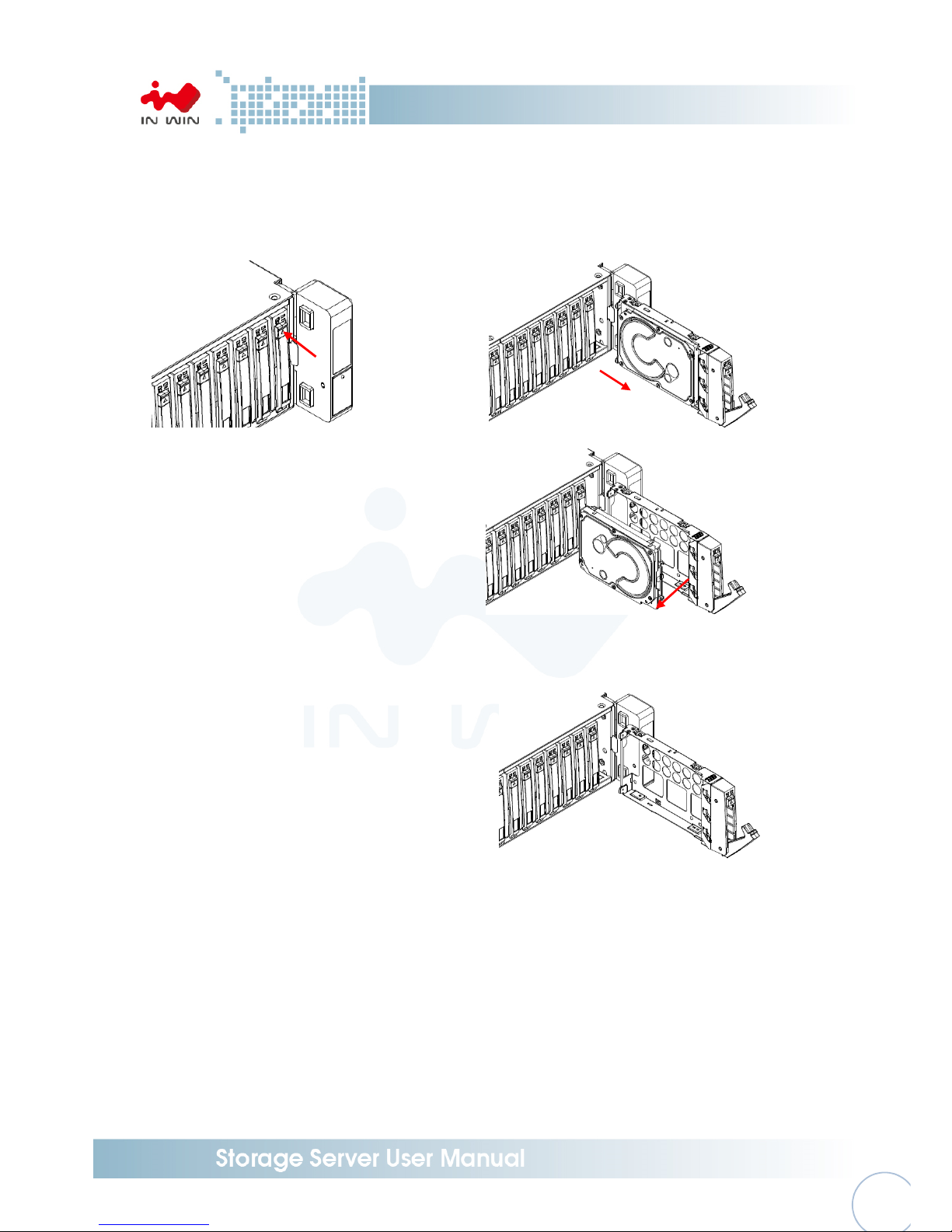
2.1.2 Removing a Hard Drive
Step 1: Press the release button then pull outward the handle to release the disk tray
Step 2: Press the clip on the right side and hold to pull out the hard drive
Step 1 Step 2
Press
Pull
Pull
Page 14
- 13
-
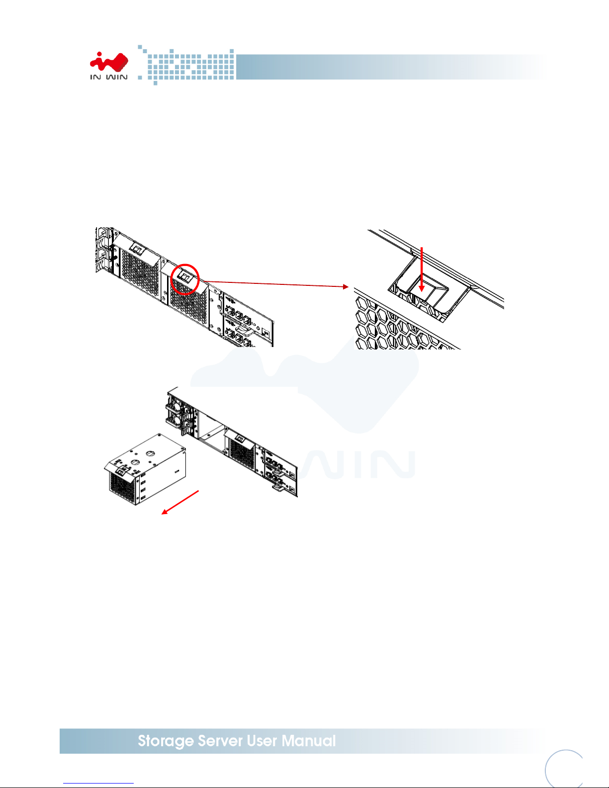
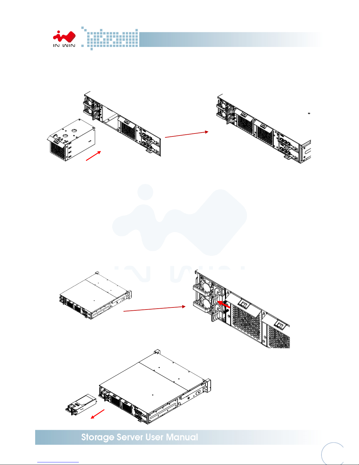
2.2 Removing and Installing a Fan Module
In Win IW-RJ series JBOD is equipped a pair of fan module. These fan modules support hot swap
and redundancy. Once any of the fan fails, user can easily replace and maintain the system.
2.2.1 Removing a Fan Module
Step 1: Press the clip as Step 1 shows
Step 2: Pull out the fan module
Step1
Step2
Press
Pull
Page 15
- 14
-
2.2.2 Installing a Fan Module
Step 1: Push the fan module into the cage until hearing “click”
Step 1
2.3 Removing and Installing a PSU Module
In Win IW-RJ series JBOD built-in a redundant power supply module. With this function, system is
capable to keep working whether as one power supply unit is failure. To replace it, user only
need to release the failure one then insert a good one.
2.3.1 Removing a PSU Module
Step 1: Press the release tab on the back of power supply unit.
Step 2: Pull the power supply unit out using the handle.
Step 1
Step 2
Insert
Press
Pull
Page 16
- 15
-
2.3.2 Installing a PSU Module
Step 1: Push the power supply into the cage until you hear a click.
Step 1
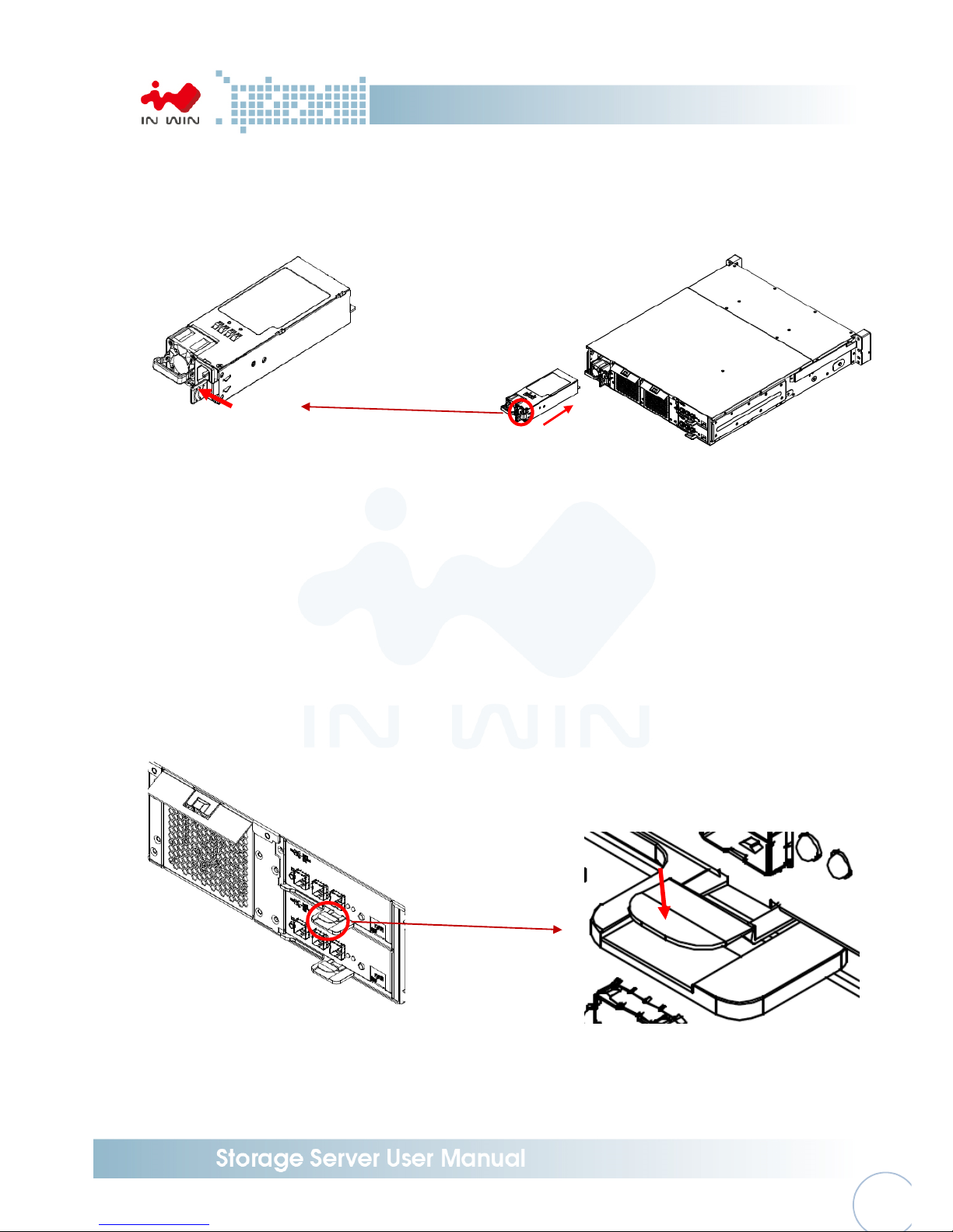
2.4 Removing and Installing a Expander Module
In Win IW-RJ series JBOD contains a set of redundant expander module. The bottom one is the
primary expander and the upper one is the secondary. The primary expander module includes an
Ethernet management module, which allow user monitor and manage the system through
Ethernet. Also the redundant module can miniature the down time once any on the expander is
fail.
2.4.1 Removing a Expander Module
Step 1: Press the clip and pull the arm as Step 1 shows
Step 2: Pull out the expander module
Step 1
Insert
Press
Press
Page 17

- 16
-
Step 2
2.4.2 Installing a Expander Module
Step 1: Push the expander module into the cage until you hear a click, and push the arm
back the original location.
Step 1
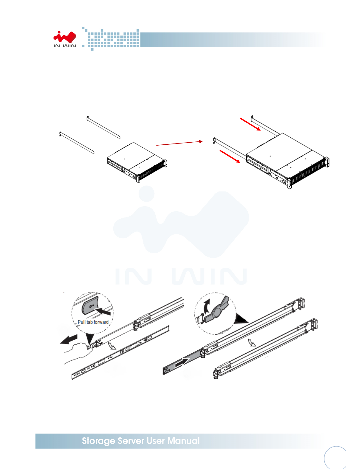
2.5 Installing Rail
In Win IW-RJ series JBOD is a rackmount model, which support EIA-RS310D standard cabinet and
chassis rack. In Win provides standard fixed slide rail to let users mount the JBOD enclosure on to
the cabinet.
2.5.1 Identifying the slide Rail
The slide rail by your order might be different. You can reference the quick installation guide
inside the slide rail package and follow the instruction to mount the rail on to your cabinet or
chassis rack.
Pull
Insert
Press
Page 18
- 17
-
2.5.2 Fixed Rail
Step 1: Insert the fixed rail from the rear side of chassis, and make sure the rail goes through
the space between chassis and the bracket. Conduct the same action to the other side.
Step 2: Use the screws in the accessory box to fix the rail and chassis on the cabinet.
Step 1
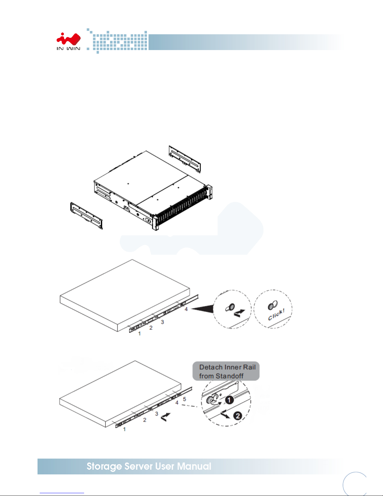
2.5.3 Slide Rail
Make sure you have a pair of slide rail, each rail has inner and rail case.
2.5.3.1 Take out the inner rail and slide the intermediate rail back
Step 1: Pull out the inner rail until it hits the terminal, then pull the release tab to
unlock.
Step 2: Pull the latch on the medium rail and push back the medium rail back.
Step 1 Step 2
Insert
Page 19
- 18
-
2.5.3.2 Attach the inner rail to the chassis
Step 1: Removing the bracket of the both sides to reveal the standoff.
Step 2: Install the inner rail onto the chassis. Make sure the key holes and the standoff
are well locked which you will hear a click.
Step 3: Repeat the same action to the other side.
Step 4: When removing the inner rail, pulling the latch upward and release the keyhole
from standoff to detach the inner rail. (Action and in the figure)
Step 1
Step 2
Step 4
Page 20
- 19
-
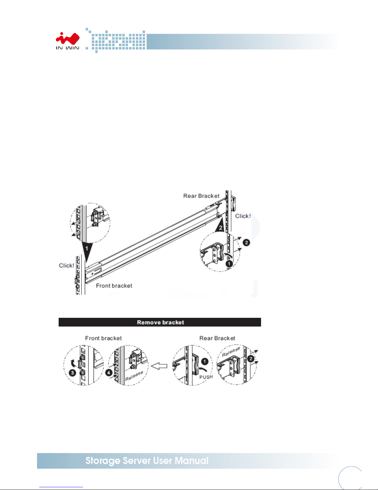
2.5.3.3 Mount the rail bracket to the cabinet
Step 1: Extend the bracket over the rear rack of the cabinet.
Step 2: Pull back to and push bracket’s standoff into the screw holes on the rack, if
your action is correct, you will hear a click.
Step 3: Extend the opposite side of bracket to the front rack of the cabinet.
Step 4: Pull the bracket to let the standoff over the screw holes on the front rack until
you hear a click.
Step 5: The other side of rail is symmetrical, repeat the installation Step 1-4.
Step 6: Once you would like to detach the bracket, pull the release tab on the rear
bracket and Pull the latch on the front bracket to release the bracket. Repeat
the same action to the other side.
Step 1~4
Step 6
Page 21
- 20
-
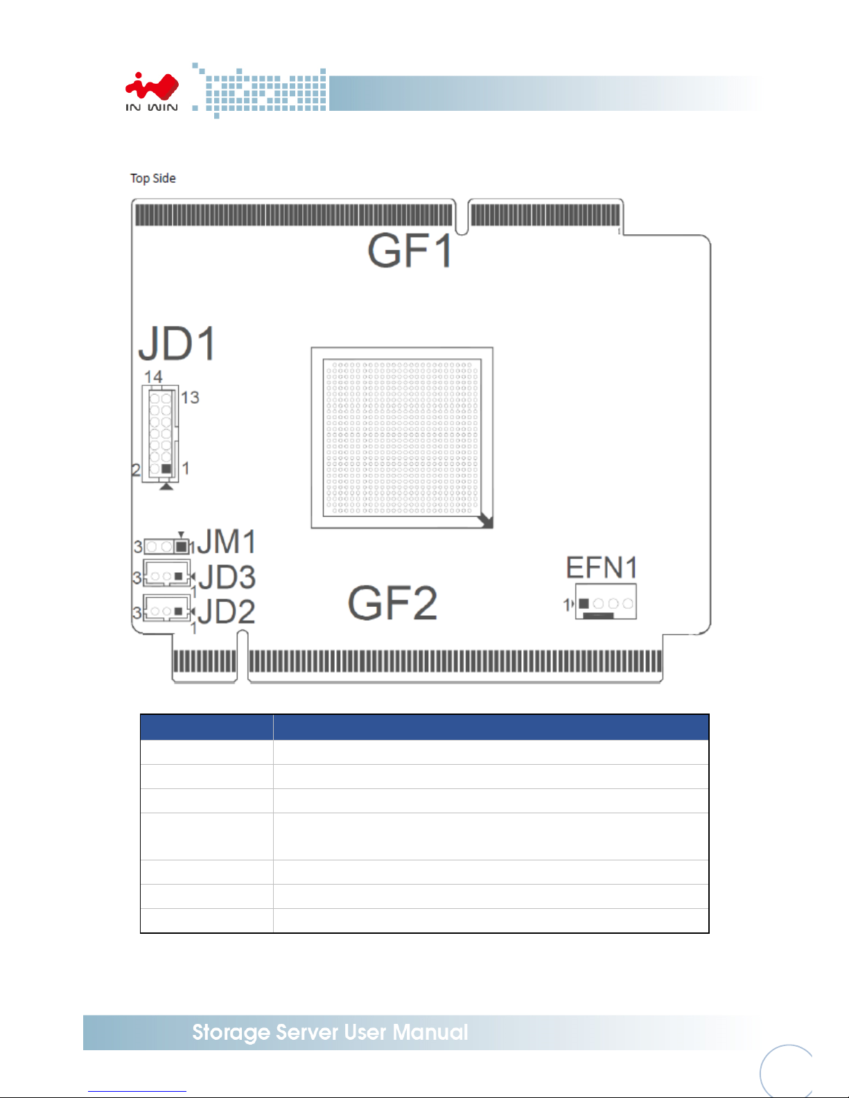
3 Expander Board Introduction
Location Description
GF1 BP Golden Finger Connector
GF2 IO Board Golden Finger Connector
EFN1 Expander FAN Connector
JM1
Single/Dual Power Module Select:
Single: Jumper 1-2; Dual: Jumper 2-3
JD1 ICE Debug Port
JD2 Smart Console
JD3 Debug Port
Page 22

- 21
-
4 Ethernet Management Card Introduction
Location Description
SW1 USB Reboot
SW2 System Reset
DP1 Power LED
DP4 MCU Status LED
JN2 UART Port
CON1 USB Port
JN1 UART Port
CON2 Ethernet Port
Page 23

- 22
-
5 Compatibility Lists
To reach best performance and avoid system failure, In Win strongly recommend users choosing the
components from In Win’s compatibility list. All the components are tested in In Win’s lab and assured
the components are working well with In Win’s chassis. The compatibility lists include:
1. Hard Disk Compatibility List
2. HBA/ RAID Card Compatibility List
You can download the latest updated list from In Win’s website:
https://www.in-win.com/en/ipc-server
6 User Interface Introduction
6.1 Overview
IN WIN JBOD System is a high performance, reliable storage system with sensors to monitor
system health. We provide state-of-the-art management functionality for users to monitor and
manage JBOD systems efficiently and flexibly. Users can manage JBOD systems through serial port
and/or Ethernet according to the system configuration on the system. We support varieties of
network protocols for network management including Telnet, SSH, Web-GUI, SNMP and SMTP.
We also support active system alert function by sending information to the email addresses
specified in the system so the users can be informed any changes of the systems in a timely
manner.
This users’ manual is for all IN WIN JBOD systems including RJ-212, RJ-224, RJ-316 and RJ-424. It
provides the information and instruction of frequent use function. Users please refer to the table
of contents to find the topics.
6.2 Key Features
Reliable High Data Rate support (up to 12Gbps)
SAS 12Gbps support and SATA3 6Gbps support to provide a reliable high performance data
rate.
Dual Expanders Support
System can accommodate dual expanders to support data redundancy capability.
Power Redundancy
System can accommodate 2 PSUs with PMBus as redundancy. Either PSU can work
independently while the other is failed.
PSU hot-swap-able
PSU is hot-swap-able. No need to shutdown system for PSU replacement in case either PSU
failure happens.
Page 24

- 23
-
Fan Modules hot-swap-able
Fan Module is hot-swap-able. No need to shutdown system for system fan module replace
in case any of the system fans failure happens.
System Fault Alarm
System Fault red LED indicator on the front panel illuminates and Buzzer sounds while there
is system fault.
Buzzer sounds differently according to the system fault. Please see the below the definition
High Temperature : 1 short beep
PSU failure : 2 short beep
Fan failure : 3 short beep
The beeps can be muted by pressing the mute button on the front panel.
HDDs hot-swap-able
HDD is hot-swap-able. No need to shutdown system for HDD installation and/or
replacement while there is HDD failure happens or intend to add new HDD to the system.
Smart Fan Control
The Fan modules are smartly controlled by the firmware to provide 7 levels speeds
according to the system temperature detected by the temperature sensors on Expander
chips and Backplane.
Zoning
System support the feature to divide disk drives into 2 different groups. Each group can own
users-configurable number of HDDs independently. This feature enables single JBOD serving
2 hosts.
Cascading
There is a cascading port on Expander for cascading another JBOD system to expand disk
space whenever the system is running out of space.
6.3 Software Management
6.3.1 System Management Structure
IN WIN JBOD Systems support out-of-band Network Management feature enabling rich set
of protocols and a flexible way for SAS Expander management anytime from anywhere.
6.3.1.1 With Ethernet Management
In this configuration, when there is an Ethernet board on top of the Primary SAS
Expander module, users can manage Primary and Secondary SAS expanders through
RS-232 port no matter the serial console is connected to Primary or Secondary SAS
Expander module.
Page 25

- 24
-
With proper IP address setting, Users can manage system through Telnet, SSH, Web-
GUI and SNMP remotely.
6.3.1.2 Without Ethernet Management
In this configuration, when there is no Ethernet board, Users can only manage Primary
or Secondary SAS Expanders by connecting serial console cable to Primary or
Secondary SAS Expander module separately. And, in such configuration, Users won’t
benefit from the rich set of network protocols management.
Page 26

- 25
-
6.3.1.3 Network Protocols Support
As an Ethernet Management board exists, rich set of network protocols are leveraged
for flexible remote management. The supported protocols are Telnet, SSH, Web-GUI,
SNMP and SMTP.
Please be sure the IP address of the system is correctly configured to enable network
management. Our systems support Static IP address or DHCP dynamic IP address as
per users’ configuration.
6.3.1.4 Operation Modes
IN WIN JBOD systems Ethernet Management provide a flexibility of modes for different
scenarios by simply applying CLI commands to change.
Ethernet management support 2 modes – Normal Mode and Alone Mode.
Normal Mode:
One Ethernet board in a JBOD enclosure. It can be either only one SAS Expander or 2.
Page 27

- 26
-
In this mode, users can manage both SAS Expander by only one Ethernet board. This is
the default operation mode of the Ethernet mgmt. board. To check the operation
mode, applying hidden command “save alone” to view. “save alone 0” for Normal
mode.
Whenever the Ethernet mgmt. board run in Normal mode. There are 2 sub-directories
“Primary” and “Secondary” being seen and users can change directory to then for SAS
Expander management.
Page 28

- 27
-
Discrete Mode:
Ethernet Board to manage the SAS Expander it resides. There should be Ethernet
board on any SAS Expander so it provide Network Management capability.
In this mode, users can manage the SAS Expander the Ethernet board resides on. Users
will need 2 Ethernet board to manage both SAS Expander through network.
To check the operation mode, apply hidden command “save alone” in /mgmt.s# layer
to view.
To enable the Alone mode, simply apply a hidden command “save alone 1” in
/mgmt.s# layer to enable.
To disable the Alone mode (set to Normal mode), simply apply a hidden command
“save alone 0” in /mgmt.s# layer to disable.
Page 29

- 28
-
Please be sure to enable Alone mode on both Ethernet mgmt. boards and do a system
reboot so the Alone mode can work properly.
Whenever the Ethernet mgmt. board run in Alone mode. There is only one sub-
directory “Expander” can be seen and jump to it for SAS Expander management.
6.3.2 Serial Port Management
RS-232 port on Expander module provides a serial connection for users to manage JBOD
system with terminal application such as Tera Term, Hyper Term…etc. To manage JBOD
system through serial port, the settings below have to be properly configured to make it
work.
Baud Rate : 115200
Data : 8 bit
Parity : None
Stop Bit : 1 bit
Flow Control : None
Page 30

- 29
-
6.3.2.1 CLI
Depending on the system configuration, there are 2 scenarios of CLI usage will be met.
One is Expander with Ethernet management board and the other is Expander w/o
Ethernet management board.
6.3.2.1.1 Scenario 1: Expander with Ethernet board
As an Ethernet Management board exists, rich set of network protocols are leveraged
for flexible remote management. The supported protocols are Telnet, SSH, Web-GUI,
SNMP and SMTP.
“/mgmt.s#” prompts in Console Terminal means the system is with Ethernet board
installed which supports Network management with properly configured IP address.
When “/mgmt.s#” prompts, Users are on the layer of the Ethernet board
configuration. Users can configure IP address, manage users account, control services,
reboot system…etc. on this layer.
“list” command to display all the Ethernet layer commands the system supports.
“?” for Help.
“version” command to display system hardware, firmware version information.
Page 31

- 30
-
Type “<command>” for displaying the current setting of the specific command.
Type “<command> ?” for displaying specific command usage.
Page 32

- 31
-
“cd primary” to change directory for primary expander management.
“cd ..” to change directory back to upper layer. Usually used on changing from
expander layer back to Ethernet layer.
“cd secondary” to change directory for secondary expander management.
The changes have been made would take effect immediately as the running-config.
Please be sure to apply “save” command so the changes being made would be saved
for use in next reboot as the start-config. Or, the changes would lose.
Page 33

- 32
-
6.3.2.1.2 Scenario 2: Expander w/o Ethernet board
When there is no Ethernet Board on top of the Primary Expander module users need
to connect serial console to Primary or Secondary Expander for managing them
separately.
“bpP >” or “bpS >” prompts in Console Terminal means the system is without
Ethernet board installed and no network access support.
“bpP >” prompts meaning serial console is connecting with Primary Expander.
“bpS >” prompts meaning serial console is connecting with Secondary Expander.
“?” or “help” command to display the commands help detailing how to use the
console commands. For Example, “rev” to display firmware version, “sys” to display
system status, “reset” to reset Expander watch dog.
“? <command>” to display usage of the specific CLI command.
Page 34

- 33
-
Please note that the JBOD systems share the same Expander CLI commands no matter
it is with or without Ethernet Management board inside unless otherwise specified.
6.3.3 Network Management
An Ethernet Board is required to support Network management. The Ethernet board sits on
top of the Primary Expander module to provide Network Management in various protocols
such as Telnet, SSH, Web-GUI, SNMP. It also provides email message sending while there is
an alarm occurring by properly configuring the SMTP information.
While there is an Ethernet Board on top of the Primary Expander module it provides a
flexible way to manage both Expanders through any physical RS-232 port on either Primary
Expander or Secondary Expander by changing directory to /primary or /secondary.
The default setting of the Ethernet board is as below.
IP Address : 192.168.100.1
Subnet mask : 255.255.255.0
Gateway : 192.168.100.254
Username : admin
Password : default
* Please be sure the management host is in the same IP network domain as the system.
* Users can make changes of the settings to meet the network environment.
Page 35

- 34
-
* For security reason, we strongly recommend users to make change of the password
immediately right after the system is setup online.
6.3.3.1 Telnet
Telnet is default enabled in Ethernet service. It provides the same level of CLI
commands as it is through RS-232 console port.
The difference from serial console is it requires Credential - Username and
Password to gain access to Telnet session.
6.3.3.2 SSH
SSH is default enabled in Ethernet service. It provides the same level of CLI
command as it is through serial console or Telnet session.
SSH provide a secure connection between host and JBOD system. It is default
enabled on most Linux OSes. There are some freeware SSH tools for Windows to
use such as Putty, Tera Term, …etc.
Below is the Tera Term example to establish SSH session.
Page 36

- 35
-
Page 37

- 36
-
Page 38

- 37
-
6.3.3.3 Web-GUI
Web-GUI is the easiest way to manage JBOD system. It is default enabled on
system.
Users can simply open Web Browser and giving the JBOD management IP address
in URL address field to start accessing system
Login Page
Page 39

- 38
-
Version Page
System Page
Page 40

- 39
-
6.3.3.4 SNMP
SNMP is a popular network device management protocol that is widely used by IT
people to manage systems, devices and equipment which are with SNMP support.
IN WIN JBOD system has SNMP agent inside the network management board
supporting SNMP v1 and v2c.
Users need to configure the same read and write community string in JBOD
system as the SNMP manager so the system can be managed by the SNMP
Manager.
An IN-WIN proprietary MIB which define system information is required to
compile to SNMP Manager so the OID is able to be accessed properly.
inwin-jbod.mib
SNMP Setting on System
Users can change the setting through CLI and Web-GUI as necessary.
Check via CLI
Page 41

- 40
-
Check via Web
Page 42

- 41
-
SNMP Manager
Any SNMP Managers can be used to access system information by properly
configuring system setting including IP address, Read community string, Write
community string to match the setting on system. And compile IN WIN JBOD
MIB file to the manager is necessary. Below an example to browse the system
MIB with a free tool.
Page 43

- 42
-
6.3.4 Version Information
Users can check the system hardware and firmware version through various ways.
6.3.4.1 CLI (UART without Ethernet Board)
“sys rev” display compact Expander hardware, firmware and MFG version.
“rev” display verbose system version information.
Page 44

- 43
-
6.3.4.2 CLI (UART, Telnet and SSH with Ethernet Board)
Type “version” command on Ethernet Layer to display all the version information
including Ethernet firmware version, Expander HW version, Expander firmware
version and MFG CFG file version
Page 45

- 44
-
To check SAS Expander versions only, users can change directory to Expander layer
and type “sys rev” command to check Expander version information
Page 46

- 45
-
6.3.4.3 Web-GUI
Type system IP address on Web Browser URL address field to gain access to the
system. After logging in, click “Version” button on the left pane to view the system
version information on the right pane. Scroll down to view all information if the
display is out of page.
6.3.5 System Status
System Status is to display the status of the system sensors including temperature, voltage,
fan speed and Power Supply.
There are 1 temperature sensor on each Expander, 2 system temperature sensors on
Backplane, 5V and 12V voltage sensors on backplane, 4 Fan speed sensors on backplane and
2 Power Supply health sensors on PDB.
6.3.5.1 CLI (UART without Ethernet Board)
Type “sys alarm” on console to check the system sensor’s readings and their
status.
Connect serial cable to Primary and Secondary Expander to check the status
respectively. As the design, both Primary and Secondary Expanders would get the
same reading and status (except Exp Die Temperature) since they are from the
same sensors.
Page 47

- 46
-
Page 48

- 47
-
6.3.5.2 CLI (UART, Telnet and SSH with Ethernet Board)
Type “sys alarm” command on Expander layer would display the System sensors’
reading and their status.
Please note that the Expander temperature sensor “Exp Die” is located on the
Expander chip so need to change directory to Primary and Secondary to read its
status respectively.
Page 49

- 48
-
6.3.5.3 Web-GUI
Type system IP address on Web Browser URL filed to gain access to the system.
After logging in, click “System” button on the left pane to view the system status
information on the right pane. Scroll down to view all information if the display is
out of page.
Page 50

- 49
-
6.3.6 Network Settings
Network settings is for displaying and setting the system network information including
Current Network Status, DHCP/Static IP Address selection, Network Services, Mail
configuration, SNMP configuration.
6.3.6.1 CLI (UART, Telnet and SSH with Ethernet Board)
There are a couple network setting commands on Ethernet layer such as “ipaddr”,
“gateway”, “netmask”, …etc. to view and configure the setting respectively. Please
refer to Management\CLI session for more details in how to use the CLI
commands.
Please be sure to apply “save” command so the setting would be saved for next
system reboot.
Page 51

- 50
-
6.3.6.2 Web-GUI
Type system IP address on Web Browser URL filed to gain access to the system.
After logging in, click “Network” button on the left pane to view the network
information on the right pane. Scroll down to view all information if the display is
out of page.
Page 52

- 51
-
6.3.7 Disk Information
Disk information is to show the disk drives status on the system including Bay id, Phy id, SAS
Address, Link speed and current status.
6.3.7.1 CLI (UART without Ethernet Board)
Type “sys hdd” command to display the system hard disk drives status on the
system.
6.3.7.2 CLI (UART, Telnet and SSH with Ethernet Board)
Type “sys hdd” command on Expander layer would display the system hard disk
drives status on the system.
Page 53

- 52
-
Page 54

- 53
-
6.3.7.3 Web-GUI
Type system IP address on Web Browser URL filed to gain access to the system.
After logging in, click “Disk” button on the left pane to view the disk drives
information on the right pane. Scroll down to view all information if the display is
out of page.
Page 55

- 54
-
6.3.8 Zone Setting
6.3.8.1 CLI (UART without Ethernet Board)
6.3.8.1.1 Type “c.zone curr” command to show the current zone running setting
6.3.8.1.2 Type “c.zone slot 1 1~6” to configure Zone 1 containing Slot 1 to Slot 6 disk
drives.
6.3.8.1.3 Type “c.zone config” to show the zone configuration the users have made.
6.3.8.1.4 Type “c.zone down 1” to configure the Exp. Port of the 3 SAS ports belonging
to zone group 1.
6.3.8.1.5 Type “c.zone enable” to enable Zoning setting of the system.
6.3.8.1.6 Type “c.zone disable” to disable Zoning setting of the system.
6.3.8.1.7 A system reboot is required to make the Zone configuration take effect.
6.3.8.1.8 Please note that the Zoning setting is only made for the expander the serial
port is currently connected. To make both expander, please do it again on
other Expander.
6.3.8.2 CLI(UART, Telnet and SSH with Ethernet Board)
6.3.8.2.1 Type “c.zone curr” command on Expander layer would display the current
zone running setting
Page 56

- 55
-
6.3.8.2.2 Type “c.zone slot 1 1~6” to configure Zone 1 containing Slot 1 to Slot 6 disk
drives.
6.3.8.2.3 Type “c.zone config” to show the current zoning configuration. A system
reboot is required to make the configuration take effect.
6.3.8.2.4 Type “c.zone down 1” to configure the Exp. Port of the 3 SAS ports belonging
to zone group 1.
6.3.8.2.5 Type “c.zone enable” to enable Zoning setting of the system.
6.3.8.2.6 Type “c.zone disable” to disable Zoning setting of the system.
6.3.8.2.7 A system reboot is required to make the Zone configuration take effect.
6.3.8.2.8 Please note that the Zoning setting is only made for the expander the console
is currently on. To make both expander, please do it again on other Expander.
Page 57

- 56
-
6.3.8.3 Web-GUI
6.3.8.3.1 Type system IP address on Web Browser URL filed to gain access to the
system. After logging in, click “Zone” button on the left pane to view and
configure the Zoning setting of the system
6.3.8.3.2 “Current Zone Configuration” session shows the current zone setting on the
system including the disk bay assignment of zone and the cascading port zone
group.
6.3.8.3.3 “New Zone Configuration” session allow users to configure zone setting on
the system in an easy way by selecting the disk bays and the zone group the
cascading port belonging to. Click “Apply” to make the configuration take
effect.
6.3.8.3.4 Whenever there are 2 SAS Expanders on the system, the Zoning setting
applies to both of them at once while configuring through Web-GUI.
Page 58

- 57
-
6.3.9 Firmware Upgrade
Firmware upgrade function provides a way to update system firmware when necessary.
There are 3 firmware for IN WIN JBOD system:
1. Ethernet Management board Firmware (when there is Ethernet Management board)
2. SAS Expander Board Firmware
3. SAS Expander MFG CFG binary
There are a couple ways to upgrade system firmware according to the HW configurations.
Please note that the upgraded firmware won’t take effect immediately until a system reboot
6.3.9.1 CLI (UART without Ethernet Board)
When there is no Ethernet Management board on the system users can upgrade SAS
Expander firmware and MFG CFG file through Xmodem protocol. Most of serial
console terminal tools such as Tera Term support Xmodem protocol for sending file to
system.
The Firmware upgrade has to be done on both the Primary and Secondary SAS
Expander separately whenever there is a Secondary SAS Expander on the system
Page 59

- 58
-
6.3.9.1.1 SAS Expander Firmware
A. “fwdl” command on serial console.
B. Type “y” to commit firmware upgrade.
C. Select xmodem as the protocol to transfer file.
Page 60

- 59
-
D. Select the correct SAS Expander firmware file.
E. Click on “Open” to start the selected firmware transferring to SAS Expander.
F. Serial console would then start firmware transfer.
G. After firmware transfer completed, reboot Expander to activate new firmware.
Page 61

- 60
-
6.3.9.1.2 SAS Expander MFG CFG binary
A. Similar to firmware upgrade, typing “mfgdl” on console.
B. Type “y” to commit MFG file upgrade.
C. Select xmodem as the file transfer protocol.
D. Select the correct MFG CFG file from file browser.
E. Click “Open” to start file transfer.
F. Serial console would then start file transfer.
G. Reset Expander to activate MFG CFG file by applying “reset” command or power
recycle the system.
Page 62

- 61
-
6.3.9.2 CLI (Telnet or SSH with Ethernet board)
When there is an Ethernet Management board on the system users should upgrade
Ethernet Board firmware, SAS Expander firmware and MFG CFG file through network
instead of xmodem when using CLI commands.
All sort of firmware upgrade goes through TFTP and the system would intelligently
upgrade firmware to the right hardware. More conveniently, both the Primary and
Secondary SAS Expanders would be upgraded at the same time when upgrade
command is applied.
Run a TFTP server on your computer and assign the “Current Directory” with the path
to where the firmware is stored. Assign “Server interface” with the IP address in the
same domain as JBOD system. (Please be sure to configure TFTP server accordingly if
you are using different TFTP server from the one in the example)
Do not power off system while firmware is upgrading or it might crash the system.
New firmware does not take effect until a system reboot.
Page 63

- 62
-
6.3.9.2.1 Ethernet Management Board Firmware
“upgrade <tftp_server_ip> <filename> command to start Ethernet Firmware upgrade.
Page 64

- 63
-
6.3.9.2.2 SAS Expander MFG CFG binary
Same as above by using the Expander Firmware filename in command.
Page 65

- 64
-
6.3.9.2.3 SAS Expander MFG CFG binary
Same as above by using the Expander MFG CFG binary filename in command.
Page 66

- 65
-
6.3.9.3 Web-GUI (with Ethernet board)
When there is an Ethernet Management board on the system users can upgrade
system firmware through Web-GUI other than CLI in console or Telnet session.
Upgrade system firmware through Web-GUI is much easier than other ways. Just
simply select the firmware by file browser and click ‘Apply’ to start.
All the firmware including Ethernet board firmware, SAS Expander firmware and MFG
CFG file apply the same way to upgrade.
After system upgrade, be sure to reboot system to take effect the new firmware which
has been upgraded to the hardware.
6.3.9.3.1 Open Web browser and give the URL filed with system IP address.
6.3.9.3.2 Given username and password on the Welcome page.
Page 67

- 66
-
6.3.9.3.3 Click “Tool” button on the left pane and scroll down to “Software Upgrade”
session on the right pane.
6.3.9.3.4 Click “Choose File” button to select the firmware being upgraded from file
browser and click “Open” to commit.
The firmware can be Ethernet board firmware, SAS Expander firmware or SAS
Expander MFG CFG file. The system would intelligent detect the firmware
type and upgrade to the right hardware.
Page 68

- 67
-
6.3.9.3.5 Click “Upgrade” button to start firmware upgrade.
6.3.9.3.6 Web would direct to a page telling firmware is upgrading.
After upgrade is done, Web will direct to the Login page.
Page 69

- 68
-
6.3.9.3.7 A system reboot is require to make new firmware take effect.
6.3.10 System Logs
IN WIN JBOD systems support the capability to record system information to NVRAM for the
purpose of activities history monitoring. The recorded information will retain until users
issue clear command to erase from NVRAM or the NVRAM is full. Two categories of system
information - Info and Fail would be recorded when happens.
6.3.10.1 CLI (UART without Ethernet Board)
Users can check the system logs by connecting serial cable to Expander RS-232 port
directly. Users will need to physically connect serial cable to Primary or Secondary SAS
Expander to check the logs on it.
Page 70

- 69
-
6.3.10.1.1 “nvlogs” command to display all logs
6.3.10.1.2 “nvlogs info” to display only the information category logs.
Page 71

- 70
-
6.3.10.1.3 “nvlogs fail” to display only the Fail category logs.
6.3.10.1.4 “nvlogs clear” to erase all the logs from NVRAM
Page 72

- 71
-
6.3.10.2 CLI (UART, Telnet, SSH with Ethernet Board)
Users can check the system logs by connecting UART cable to Expander RS-232 port
directly, Telnet or SSH to the system and change directory to Primary or Secondary (if
existed) SAS Expander layer.
6.3.10.2.1 “nvlogs” command to display all logs
6.3.10.2.2 “nvlogs info” to display information category logs.
6.3.10.2.3 “nvlogs fail” to display Fail category logs.
6.3.10.2.4 “nvlogs clear” to erase all the logs from NVRAM
Page 73

- 72
-
6.3.10.3 Web-GUI (With Ethernet Board)
6.3.10.3.1 Type system IP address on Web Browser URL filed to gain access to the
system. After logging in, click “Log” button on the left pane to view and
manage the Logs of the system.
6.3.10.3.2 The Log web page provides an easier way for managing the system logs
including displaying different category of system logs and clearing the logs by
clicking on the corresponding buttons.
6.3.10.3.3 Click “Refresh” and then “Process” button to display most current system
logs.
6.3.10.3.4 Click “Waning Only” and then “Process” button to display the Warning
category system logs.
6.3.10.3.5 Click “Info Only” and then “Process” button to display the Information
category system logs.
6.3.10.3.6 Click “Clear” and then “Process” button to erase all the system logs.
Page 74

- 73
-
7 Q&A
Section 1: Expander
1. What is the In Win Expander’s function?
A: The expansion the capacity, the expander can manage more SAS drives via one SAS cable in
the JBOD.
2. Why IW-RS series storage server chassis are built-in expander board, and IW-RJ series JBOD
enclosures uses expander module?
A: IW-RS chassis needs a motherboard to compose a system, the expander board can work
seamlessly with motherboard to manager the drives. Different from the chassis, IW-RJ JBOD
enclosure use hot swap expander modules to satisfy the requirement of both capacity
expansion and JBOD redundancy.
3. Why IW-RJ JBOD enclosure needs 2 expander modules?
A: It is for redundancy. If user does not need this function, single expander module also works
out.
4. What are the functions of the three connector ports on the expander module?
A: SAS 0 is the connecting port to Server 0/ RAID or HBA 0, SAS 1/ RAID or HBA 1 is to Server 1;
EXP is the port to cascade another JBOD to expand the capacity.
Page 75

- 74
-
5. Can I add more ports to the expander module?
A: First of all, we have to understand that the ports are for cable connecting. Second, as only as
the Phy quantity of the expander chip set allows, technically, this configuration works out. Yet,
we also need to consider about the technical alignment. For example, an expander with a 3x36R
chipset has totally 36 Phy, and each ports consumes 4 Phy; thus, we can design a 9-port
expander (36/4 = 9) to connect 9 cable. However, once we use out all the Phy for connecting, we
have no remaining Phy to connect HDD, this design will goes meaningless.
6. Once I find the expander is failure, what can I do?
A: IW-RS series: Power off the system, and make sure the system is totally shut down. Unplug
the SAS cable to replace the expander board.
IW-RJ series: Remove the failure expander module, and replace a new expander module.
Section 2: Hard Disk
7. What is the different between SAS and SATA disk, and how to choose?
A: SATA has only one throughput channel for data transmission, SAS has two. Once the system is
designed with redundant function, SAS disk provides performance and reliability. SATA provide a
choice of cost selective option.
8. Are SAS and SATA disks are compatible with both In Win IW-RS series and IW-RJ series?
A: Yes, In Win IW-RS and IW-RJ support both SAS and SATA disks.
9. Can I populate 2.5” disks to the 3.5” tray-less slots?
A: 3.5” tray-less slot does not support 2.5” disks at this moment, if this requirement is
mandatory, please contact In Win sales for OEM service.
10. Is the storage server or JBOD must be full populated to work?
A: No, you can populate partial bays and start the system. Once you need more storage space in
the future, then add more disks.
11. Can I populate both SAS and SATA disks in an enclosure?
A: Yes, it works. However, you may need to consider about the alignment issue.
12. If my system drive is failure, can I replace the drive without shutting down the system?
A: In default, IW-RS series’ two internal disks doesn’t support hot-swap feature. You can order
an optional 2bay hot-swap system disk module to reach your purpose.
Page 76

- 75
-
Section 3: RAID/ Cascade
13. Is RAID card a requirement component for composing a RAID system?
A: If your motherboard featured on-board RAID function, or your OS support software RAID, you
do not need a RAID card. For technical details, please contact your motherboard or software
vendor.
14. How many units can IW-RJ series JBOD cascade?
A: In maximum, a daisy chain can stripe 48 disks.
15. If I would like to cascade the JBOD, what components do I need?
A: You will need a SFF-8644 to SFF-8644 SAS cable, which meets T10 standard. And the length
we suggest less than 3M to reach the best performance.
16. If I only have an internal RAID controller card, and I would like to expand the capacity, how to
add more disks?
A: IW-RJ series JBOD is for this purpose. If your RAID controller card does not have external
connecting port, you can use a SFF-8643 to SFF-8644 adaptor cable to connect the JBOB
enclosure.
Section 4: Others
17. Why PSU has two modules? What are these two modules for?
A: Two PSU modules are for redundancy, if you need this function, PSU with two modules is
required.
18. Can I add or reduce the quantity of fans?
A: The quantity of fan is related to the radiating efficiency. Usually, the quantity of fans depends
on the system loading and the heat generation. Unless you have tested, or we strong
recommend not to change the default fans quantity.
19. Which parts support hot-swap feature.
A: IW-RS storage server: Fans, PSU, HDD
IW-RJ JBOD enclosure: Fans, PSU, Expander Modules, HDD
20. Can 12Gb SAS ports compatible with 6Gb SAS or 6Gb SATA ports? Any adaptor can convert?
A: 12Gb SAS does not align with 6Gb SAS, so In Win does not have adaptor for this case.
21. If the arm or handle is broken, how can I fix or replace it?
A: Please contact your local In Win partner, or support contact for replacing and repair service.
Page 77

- 76
-
22. If I would like to modify the GUI, how can I access.
A: The copyright of the GUI is belonging to In Win. If you would like to amend anything of the
GUI, please contact In Win sales for ODM service.
8 Technical Support
If you need help on installation or troubleshooting, you can contact your local In Win partner, or send
email to In Win’s local contact for technical assistance.
 Loading...