

In Win IW-PE689 Installation Manual

IW- PE689
Pedestal Entry Server Chassis
(Please read the following steps to assemble)
Please note that the pictures in this installation
guide are for your reference only, and they
may vary from the actual product.
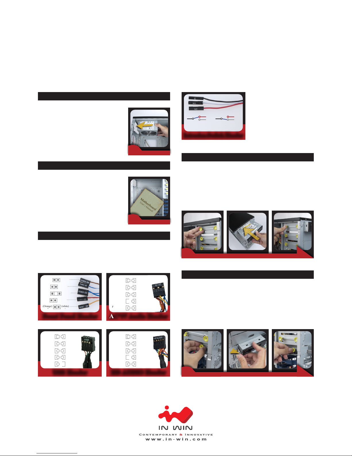
2.Remove the Front Panel
Unlock the locking tabs and remove the front panel.
= Opening the Chassis =
Installation Guide
1. Remove the Side Covers
Unscrew the Thumb screws and remove both side covers.
IW- PE689
Pedestal Entry Server Chassis
3. Insert the power supply to
the chassis with the power
supply fan facing down.
Use the mounting screws to
secure the position.
= Power Supply Installation =
4. Please follow M/B
Installation Guide to
connect power cables
to M/B.
= Motherboard Installation =
5. Connect all cables to M/B. (Included USB,
HDD LED, HD Audio, Power Switch, Power
LED, Reset Switch, Intrusion switch).
= Front I/O Wires Installation =
USB Header HD AUDIO Header
(white)(Orange)
-+
(white)(Brown)
-+
(white)(Red)
-+
(white)(Blue)
-+
(white)(Blue)
-+
VCC2
(RED)
VCC1
(RED)
21
D2(WHITE)
D1-
(WHITE)
43
D2+
(GREEN)
D1+
(GREEN)
65
GND
(BLACK)
GND
(BLACK)
87
KEYNC 9 10
MIC
(BROWN)
AUD_GND
(BLACK)
21
MIC_BIAS
(ORANGE)
AUD_GND
(BLACK)
43
FP_OUT_R
(GREEN)
FP_RET_R
(YELLOW)
65
AUD_VCC
(RED)
KEY
8
FP_OUT_L
(PURPLE / WHITE)
FP_RET_L
(BLUE)
9
Intrusion Switch Header
AC’97 Audio Header
10
MIC
(BROWN)
AUD_GND
(BLACK)
21
MIC_BIAS
(ORANGE)
AUD_GND
(BLACK)
43
FP_OUT_R
(GREEN)
FP_RET_R
(YELLOW)
65
AUD_VCC
(RED)
KEY
8
FP_OUT_L
(PURPLE / WHITE)
FP_RET_L
(BLUE)
9
C
NC
NO
When the side cover
is opened.
When the side cover
is closed.
C
NC
NO
6. Pull the “ODD Secure Clips”, put the
5.25”optical drive in and then press the
clips.Refer from the M/B Quick Reference
and Manual to connect the signal cable and
power cable.
= 5.25 ODD Installation =
7. Pull the FDD Secure Clips, push the FDD
Lock to the left, insert the FDD and press
down the clips. Refer from the M/B Guideline
to connect the signal cable, and then connect
the output power cable.
= 3.5” Floppy Installation =
Front Panel Header
 Loading...