

Page 1
User Manual
Page 2

Product Story
The A1 PLUS offers upgrades to the beloved A1 chassis.
The A1 PLUS retains its distinguished classy aesthetics
with the return of quality materials such as: tempered glass,
aluminium and steel. Minimalism never looked so exquisite!
The A1 PLUS features addressable RGB lighting,
that offers diversified color schemes by customizing
each individual light. The square structure provides
hassle-free installation, and the capacity to house powerful
hardware despite its compact size.
An InWin 650W, 80 PLUS Gold PSU is prebuilt within
the A1 PLUS with cables already managed. The A1 PLUS
also comes with two Sirius Loop addressable RGB fans,
and an enhanced Qi 1.2 10W charging panel
to charge your mobile devices!
Page 3

A1 PLUS CASE
Specifications
Model
Part Number
Colors
Case Type
Case Materials
A1 PLUS
IW-A1PLUS-BLACK
IW-A1PLUS-WHITE
Black, White
Mini ITX Tower
SECC, Tempered Glass
M/B Compatibility
Expansion Slots
Maximum Compatibility
Front Ports
Mini-ITX
PCI-E x 2
VGA Card Length: 320mm
CPU Heatsink Height :160mm
2 x USB 3.0
HD Audio
Internal Drive Bays
Thermal Solution
Compatibility
Power Supply
Compatibility
2 x 2.5"
1 x 120mm Side Fan
1 x 120mm Rear Fan / 120mm Radiator
2 x 120mm Bottom Fans
InWin 650W PSU Included ATX12V V2.4
Product Dimensions
(H x W x D)
with screw & handle height
Product Dimensions
(H x W x D)
Package Dimensions
(H x W x D)
273 x 224 x 357mm
231 x 210 x 343mm
344 x 295 x 414 mm
Net Weight
Gross Weight
■ InWin products comply with RoHS regulation.
■ Specifications may vary based on different regions.
7.1 kg/ 15.7lbs
7.9 kg/ 17.5lbs
Page 4

InWin 650W 80PLUS Gold PSU
Model
Total Power
Material
Type
PFC
Efficiency
IW-GD650PS
650W
SECC
ATX12V V2.4
Active PFC
80 PLUS Gold
MTBF (Hours)
AC Input
Fan
Operating Temperature
Range(°C)
> 100,000
100 ‒ 240Vac. 50-60Hz
120mm
0~40°C
Full Protection
Safety Certifications
Dimensions(L x W x H)
Warranty
Connectors
OCP/OVP/UVP/SCP/OTP/OPP
TUV/cTUVus/BSMI/CB/CE/FCC/EAC/RCM
/KCC/CCC
140 x 150 x 86 mm
5 Years
Motherboard 24-pin
1
CPU 4+4-pin
PCIE 6+2 pin
Peripherals
SATA
Floppy Power
1
2
0
3
0
■ InWin products comply with RoHS regulation.
■ Specifications may vary based on different regions.
Page 5

InWin Sirius Loop Fans
Model
Fan Size
Materials
Rated Voltage
Rated Power
Rated Current
Sirius Loop ASL120
120 x 120 x 25mm
PBT
DC 12V
1.2W
0.1A
ADD RGB Rated Voltage
ADD RGB Rated Power
ADD RGB Rated Current
Speed Mode
Air Flow
Air Pressure
DC 5V
1.25W
0.25A
PWM 500-1800 RPM
50 CFM
1.67mm/ H2O
Connector
Noise Level
Bearing Type
Life Expectancy
4-Pin
27 dB(A) Max.
Long Lifespan Sleeve Bearing
>30,000 hrs
■ InWin products comply with RoHS regulation.
■ Specifications may vary based on different regions.
Page 6
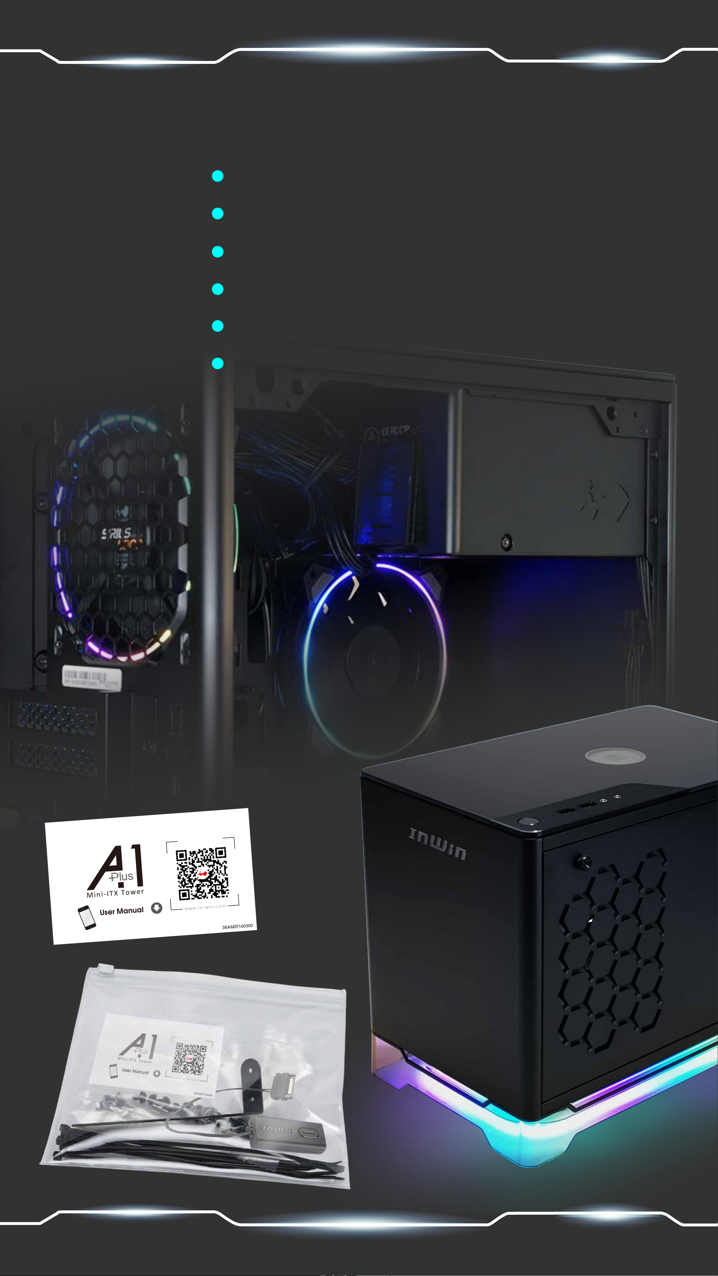
Package Content
A1 PLUS Chassis
InWin 650W 80PLUS Gold PSU
InWin Sirius Loop fans x 2
Fan RGB One-Click Controller x 1
QR Code Card
Accessory Bag
Page 7

Accessories Bag
a b
c
d
e f g
a. Hexagon Head Screws X 8
b. 2.5” HDD Screws X 10
c. Graphic Card Holder X 1
d. Cable Ties X 5
e. Anti-Slip Strips X 4
f. LED 3-Pin Header X 3
g. Fan RGB One-Click Controller X 1
Page 8

Case Structure
7
6
5
4
3
2
1
1. Tempered Glass
2. Logo
3. SECC Front/ Side Panel
4. Power Button
5. HDD/Power LED indicator
6. USB 3.0 Ports
7. Audio Ports (Earphone and Microphone)
Page 9

e
f
c
k
i
a
g
j
b
h
a. 2.5 Drive Bay
d
b. Side Fan Mounting Area
c. Rear Fan/ Radiator Mounting Area
d. Bottom Fan Mounting Area
e. Motherboard Mounting Area
f . CPU Cooler Installation Cut-Out Hole
g. PCI-E Expansion Slot
h. Extra PCI-E Supporting Mounting Hole
i. Power Supply Area
j. Fan Dust Filter
k. Wireless Mobile Device Charging Area
Page 10

Installation Guide
Please follow the related chapters to assemble
01
Opening the Chassis
For the side panel, please pull
the two tool-less tabs and lift up.
02
Motherboard
Installation
Parts Required: Hexagon Head
Screws
03
Expansion Card
Installation
Parts Required:
Hexagon Head Screws,
Graphics Card Holder
Page 11

04
I/O Wires Installation
Switch/LED Connector
Blue(P_LED) 1
White(P_LED) 3
Brown(P_SW) 5
White(P_SW) 7
2 Red (HDD)
4 White (HDD)
6 NC
8 NC
Key 9
10 NC
Page 12

05
2.5” Drive Bays Installation
Parts Required: 2.5” HDD Screws
06
Fan/ Liquid Cooling Radiator Installation
Page 13

07
Addressable RGB-Cable Installation
If your motherboard supports the addressable RGB effect,
please follow the direction of sign and connect as followed:
Connect the case’s addressable RGB Y-Cable to a motherboard’s addressable
RGB header.
Please install the 3-pin header to the available addressable RGB header of the case.
case’s addressable RGB
Y-Cable
3-Pin LED header
Motherboard
Addressable RGB Header
case’s addressable RGB
Y-Cable
The fan cable, addressable RGB Y-cable and their counterparts are attached to each.
Please connect as followed:
Installing the 1st fan: Connect the addressable RGB Y-cable to the available
3-pin addressable RGB header of the case. Connect the fan cable to
the motherboard’s fan header.
Installing the 2nd fan: Connect the addressable RGB Y-cable and connect it to the
available 3-pin addressable RGB header of the previous fan. Connect the fan cable
to the available fan header from the previous fan.
case’s addressable RGB
Y-Cable
1st fan’s addressable RGB
Y-Cable
1st fan’s fan Cable
2nd fan’s addressable RGB
Y-Cable
Motherboard
Fan Header
2nd fan’s fan cable
Page 14

If your motherboard does not support an addressable header, please use the included
Fan RGB One-Click Controller to connect to your PSU’s SATA cable and the case’s
Addressable RGB Y-Cable in order to use the 11 different lighting effects.
case’s addressable RGB
Y-Cable
case’s addressable RGB
3-Pin LED header
Fan RGB One-Click Controller
Fan’s addressable RGB
Y-Cable
Y-Cable
Hold the button to turn on or off the lights. Tap the button to change the lighting modes.
1 7
2 8
3 9
Rainbow
Breathing
Full Circle
SATA Power Input
Diagonal Transition
LED-Red
LED-Green
4 10
5
6
*InWin reserves the right to change the lighting modes.
Two-Tone Ring
Light at the end of the Tunnel
Rotating LED Trio
11
LED-Blue
LED-White
08
Anti-Slip Strips Installation
Parts Require: Anti-Slip Strips
Remove the strip covers and place them under each corner.
Page 15

09
Completing Installation
Parts Required: Cable Ties
Page 16

Notices and Warranty
■ Notices
1. Please follow the user manual for installation guidelines.
2. When installing the computer components, please use antistatic
precautions to prevent ESD (electrostatic discharge) damage.
Failure to take the necessary precautions may result in injury to
the installer and/or damage to the machine. Incorrect installation
may burnout the motherboard and other system components.
3. To avoid any damages, please do not use this product for any
other purpose than its intended use.
4. Any modifications may damage the product.
5. Please remove all internal devices before shipping or moving.
6. When storing the case, please keep this product away from high
(Including power supply, hard drives, CD-ROM, motherboard, CPU, etc.)
temperatures. Keep away from machines such as heaters that
might cause high temperatures.
7. Please do not put anything in the impeller.
8. Please do not touch the fan blades when the fan is in operation.
Please only use your fan in the computer case.
9. Please avoid unnecessary insertions and extractions to the
addressable cable as it may damage the pins.
■ Warranty
* For more detailed warranty information, please visit the
InWin retail website at www.in-win.com.
* The actual product is subject to change without prior
notice. InWin Development Inc. reserves the right to
make final modifications.
Page 17

InWin IW-WT02 Wireless Charger User Manual
Page 18

Specifications
Input
5V/2A or 12V/1.8A
Output
Support Qi 5V/1A (OUTPUT:5V/2A),
7.5W / 10W Fast Charging (OUTPUT :12V/1.8A)
Power Transfer Efficiency
78%
Product Dimensions (HxWxD)
72 x 49 x 8mm
Warranty
1-year limited warranty
(Effective date based on the purchasing date from consumers)
User Guide
1. Please make sure the power is connected.
2. Place the mobile device on the charging platform on the
top panel. Charging will begin after a “beeping” sound.
Page 19

■ Note to use
1. To avoid any computer and computer-related component damage,
please use IW-WT02 on InWin approved products.
2. To indicate that the mobile device battery is at a full charge,
the platform will continuously beep. To cease the beeping sounds,
simply remove the device.
3. Please check if the receiver is compatible with WPC Qi.
The full compatibility list can be found in the IW-WT02 user manual.
Wireless charger compatibility list
• Apple iPhone 8, 8+, XR, XS, XS Max
• Samsung Note5, S6, S6 edge+, S7, S7 edge, S8, S8+,
Note 8, S9, S9+, Note 9
• Nokia 8 Sirocco
• LG V30S, V30+, G7+ ThinQ
• Huawei Mate 20, Mate 20 Pro
• Sony XZ2, Xperia XZ2 Premium, XZ3
• Sharp AQUOS S3
• Google Pixel 3, Pixel 3 XL
• 小米 MIX 2S, MIX 3
Page 20

Copyright © 2019 InWin Development Inc. All Rights Reserved.
 Loading...