

Page 1
User Manual
Page 2
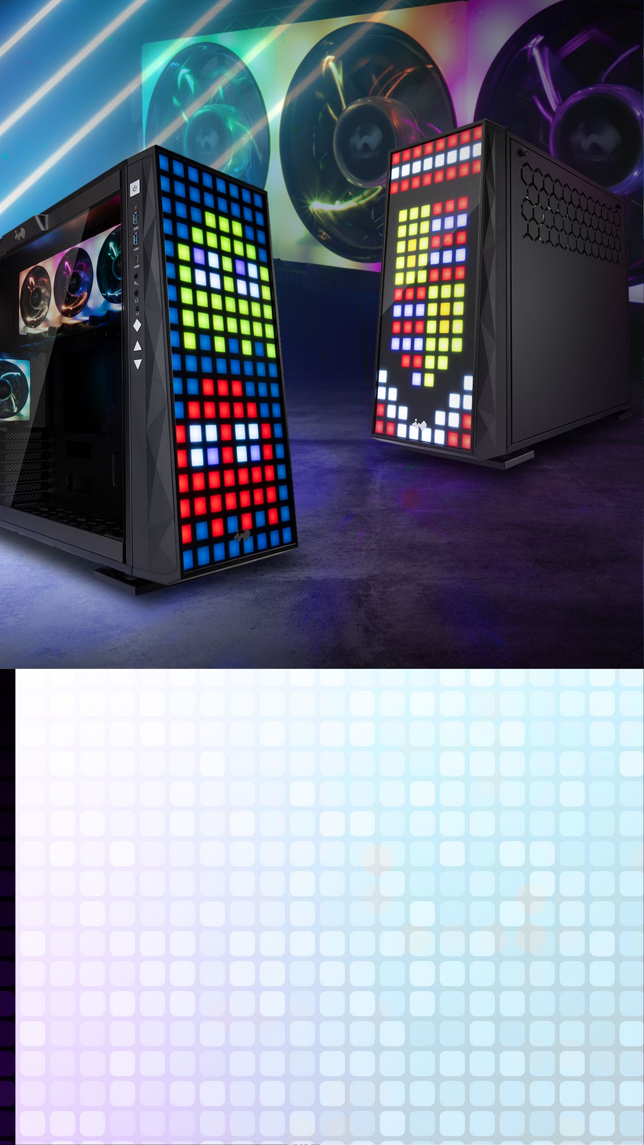
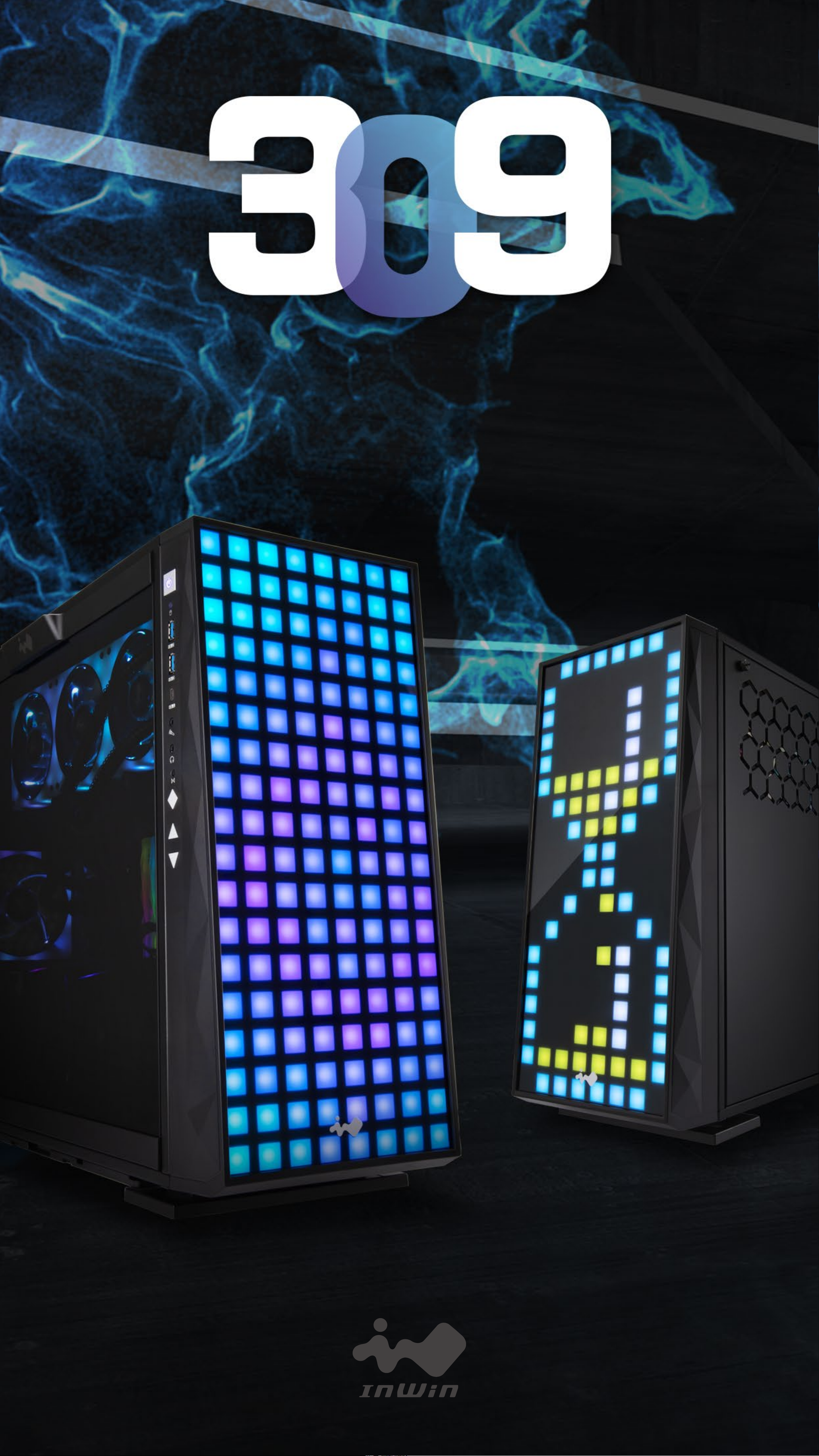
Product Story
Inspired by the beauty of stained glass, the 309
is for RGB enthusiasts that crave their PCs to
be a light show, a club or festive enough for the
holidays. Create your own designs with 144
addressable RGB LEDs! For the love of RGB, can
we get anymore LEDs?! Yes actually, by including
our EGO fans with 16 MORE LEDs per fan. The
309 will be the light of your life!
Page 3

Specications
Model 309
Part Number IW-309-Black
Colors Black
Case Type Mid Tower
Materials SECC, Tempered Glass, ABS
M/B
12" x 11" ATX, Micro-ATX, Mini-ITX
Compatibility
Expansion
PCI-E x 7
Slots
Maximum
▪ VGA Card Length: 350mm (Maximum)
Compatibility
Front Ports
▪ CPU Heatsink Height: 160mm
▪ 1 x USB 3.1 Gen 2 Type-C
▪ 2 x USB 3.0
▪ HD Audio
▪ LED & Fan Mode Button
▪ LED & Fan Control Buttons
Internal Drive
Bays
Thermal
Solution
Compatibility
▪ 2 x 3.5"
▪ 2 x 2.5" (2 Pre-Installed, Max. up to 3 bays)
▪ 1 x 120mm Rear Fan / 120mm Radiator
▪ 3 x 120mm Top Fan / 360mm Radiator
▪ 3 x 120mm Bottom Fan / 360mm Radiator (Slim)
(4 InWin EGO Fans Pre-Installed: 3 on Top; 1 at
Rear)
Power Supply
Compatibility
Product
Dimensions
(H x W x D)
Package
PSII: ATX12V
- Length up to 200mm
500 x 238 x 553mm
19.7" x 9.4" x 21.8"
335 x 618 x 706mm
Dimensions
13.2" x 24.4" x 27.8"
(H x W x D)
Net Weight 13.65kg / 30.1lb
Gross Weight 17.06kg / 37.6lb
* Our products comply with RoHS regulation.
* Specications may vary based on different regions.
* Extra fee for optional parts.
Page 4
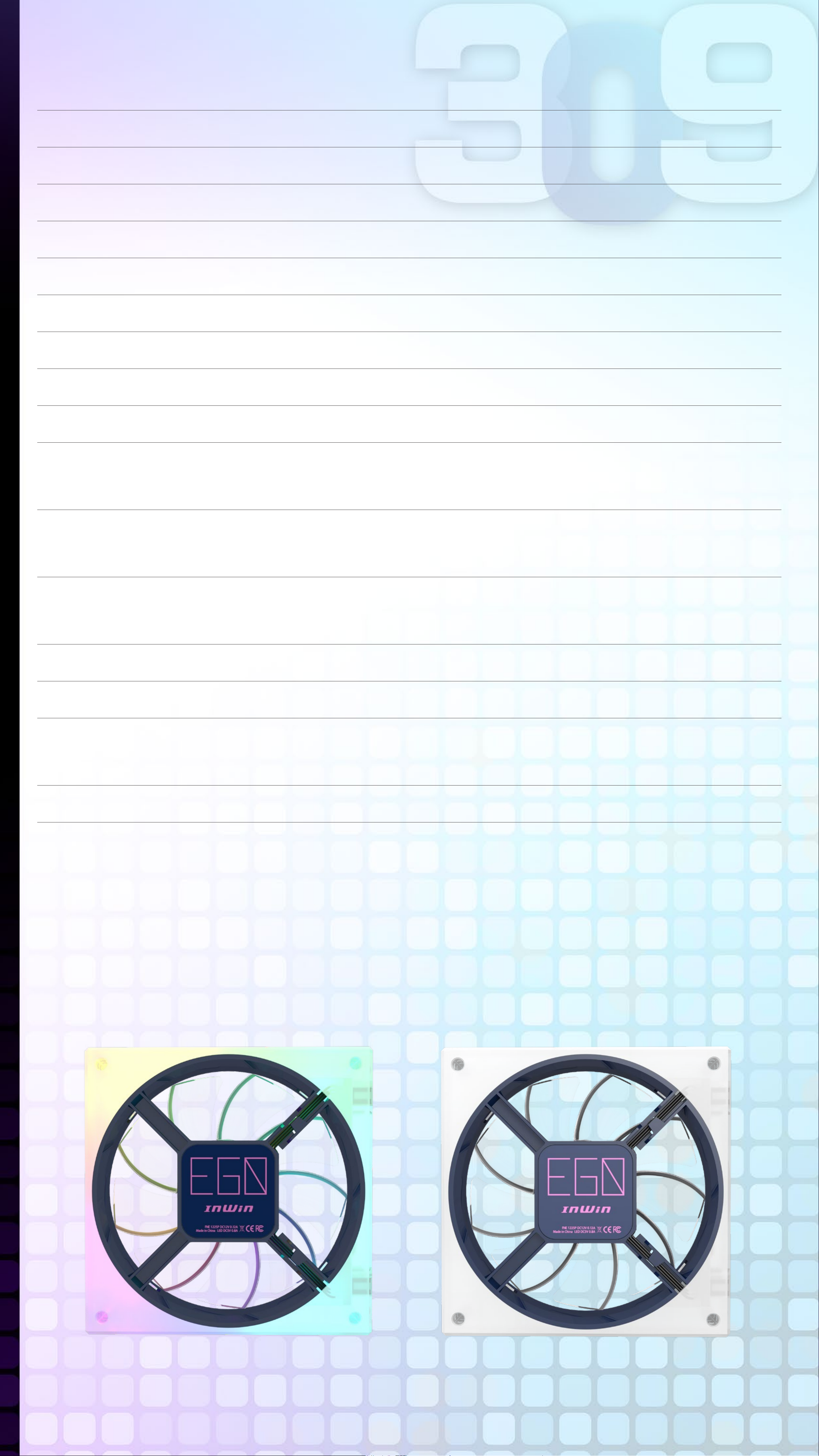
(InWin EGO Fans)
Specications
Model EGO AE120
Fan Size 120 x 120 x 25mm
Materials Silicone, PC
Rated Voltage DC 12V
Rated Power 0.76W
Rated Current 0.06A
ADD RGB Rated Voltage 5V
ADD RGB Rated Power 4W
ADD RGB Rated Current 0.8A
(PWM) 800~1400 RPM
Speed Mode
Turbo Mode: 2000 RPM Max.
40.7 CFM
Air Flow
Turbo Mode: 58.05 CFM
1.51mm/ H2O
Air Pressure
Turbo Mode: 2.74mm/H2O
LED Addressable RGB
Connector 6-Pin Modular
< 22 dB(A)
Noise Level
Turbo Mode: 32 dB(A) Max.
Bearing Type Sleeve Bearing
* Our products comply with RoHS regulation.
* Specications may vary based on different regions.
* Extra fee for optional parts.
Page 5
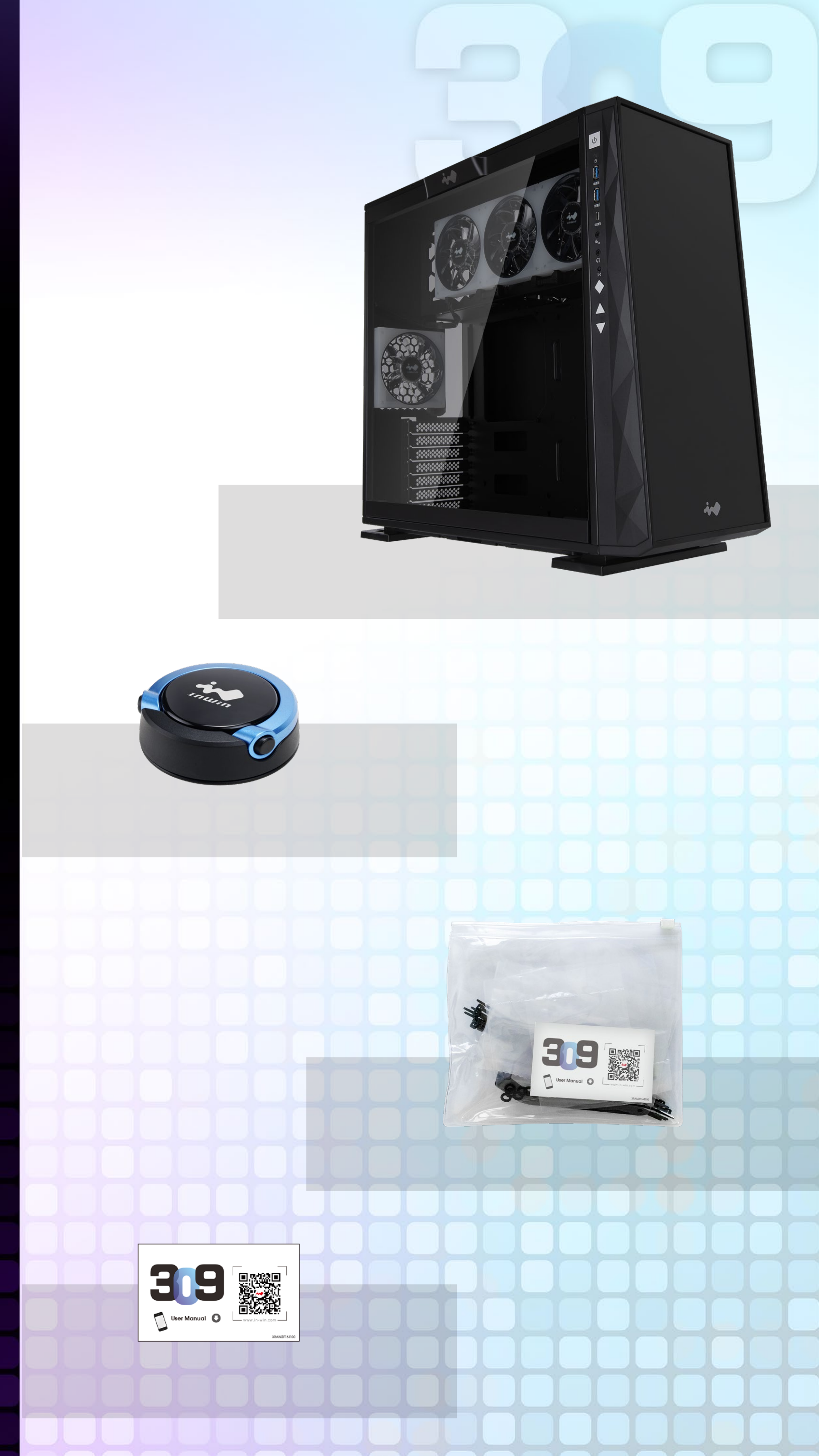
Package Contents
309 Chassis
Mag-Ear Headphone Hanger
(Random Color)
Accessories Bag
QR Code Card
Page 6
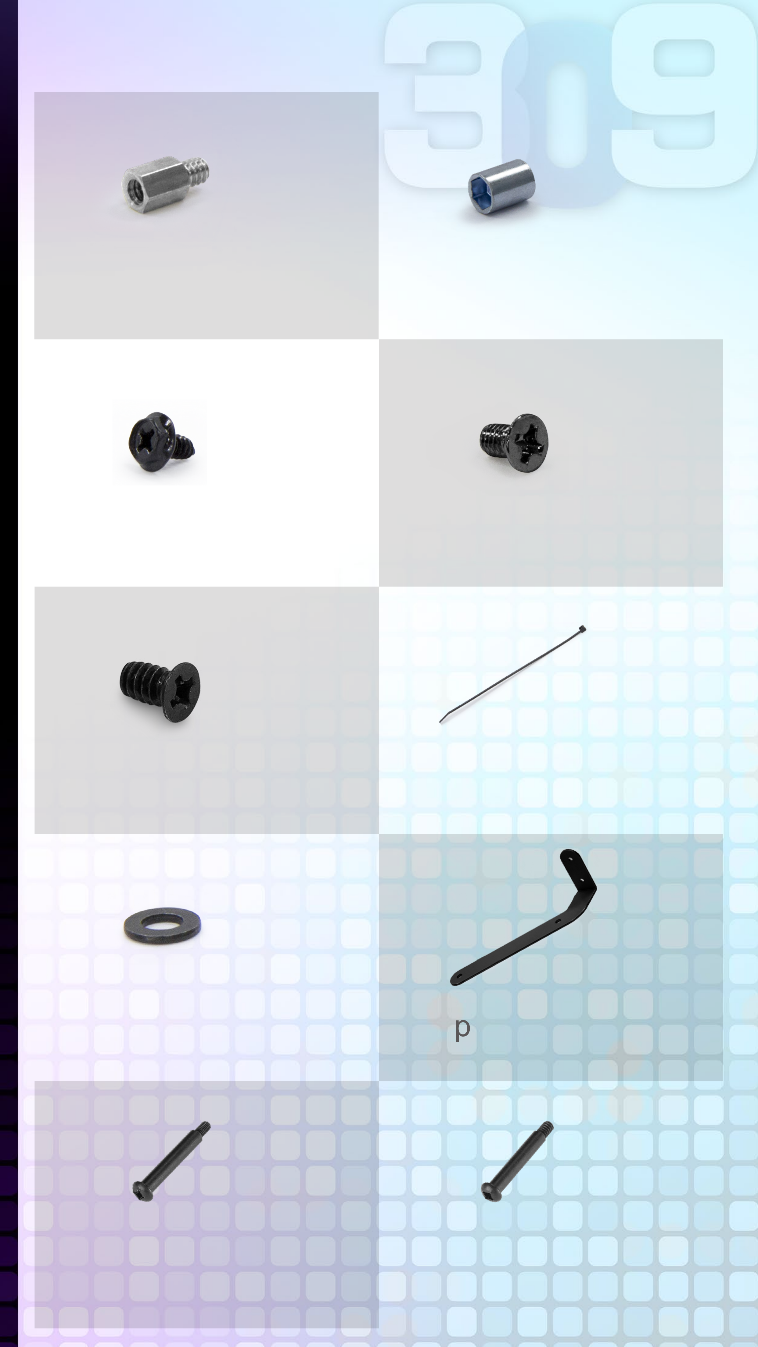
Accessories Bag
X7 X1
Motherboard
Stand-offs
Motherboard
Stand-off Socket
X18
Hexagon Head
Screws
X18
2.5" HDD Screws
X10
3.5" HDD Screws
X10
Cable Ties
X8
Water-cooling
System Washers
X1
Graphics Card Holder
X12 X12
M3 Thread Water-Cooling
Radiator Screws
(EGO Exclusive)
#6-32 Thread Water-Cooling
Radiator Screws
(EGO Exclusive)
Page 7
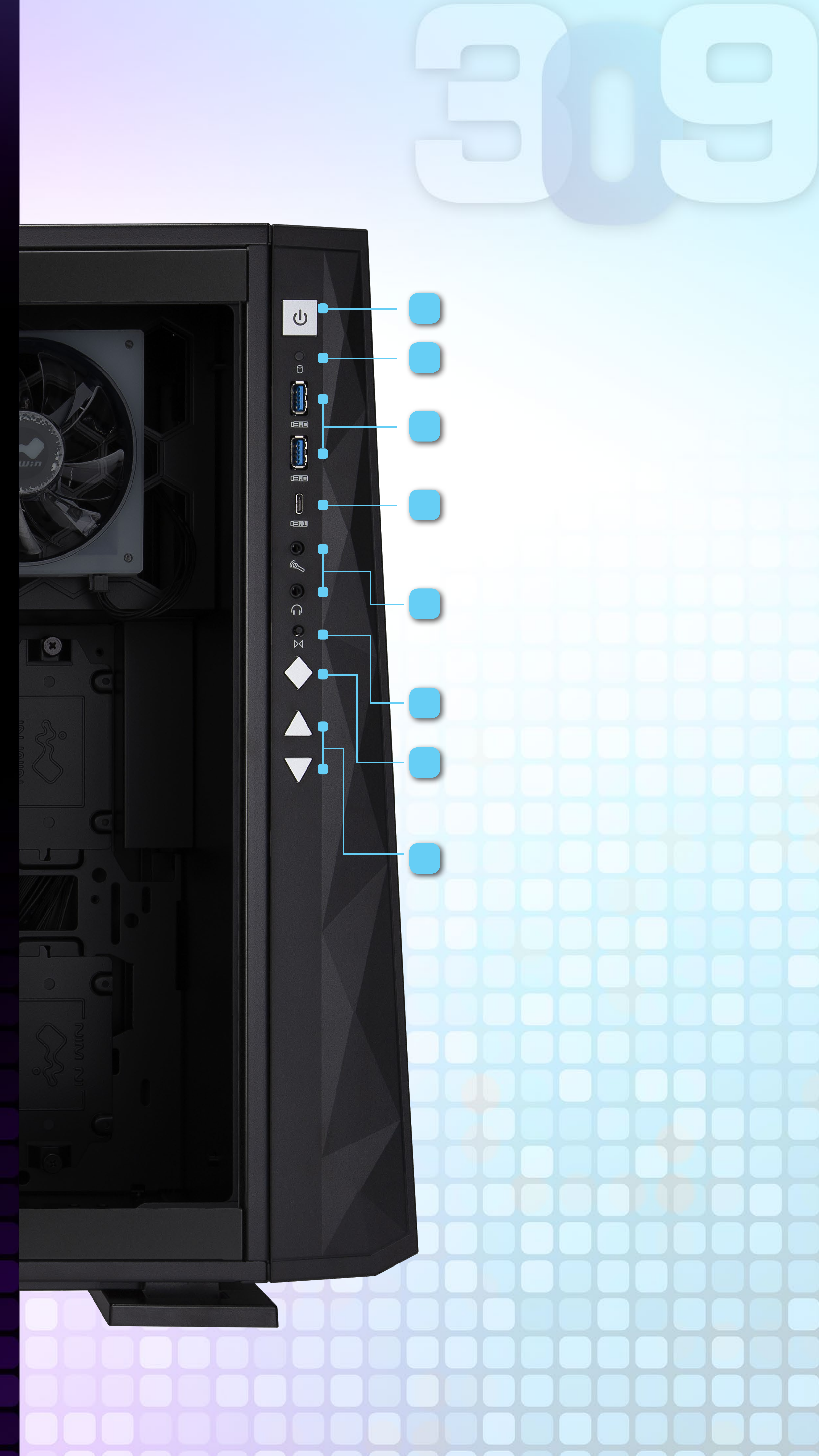
Case Structure
1
2
3
Power Button
HDD LED Indicator
USB 3.0 Ports
4
5
USB 3.1 Gen 2
Type-C Port
Audio Ports
(Earphone and Microphone)
6
7
8
Reset Button
LED & Fan Mode
Button
LED & Fan Control
Buttons
Page 8
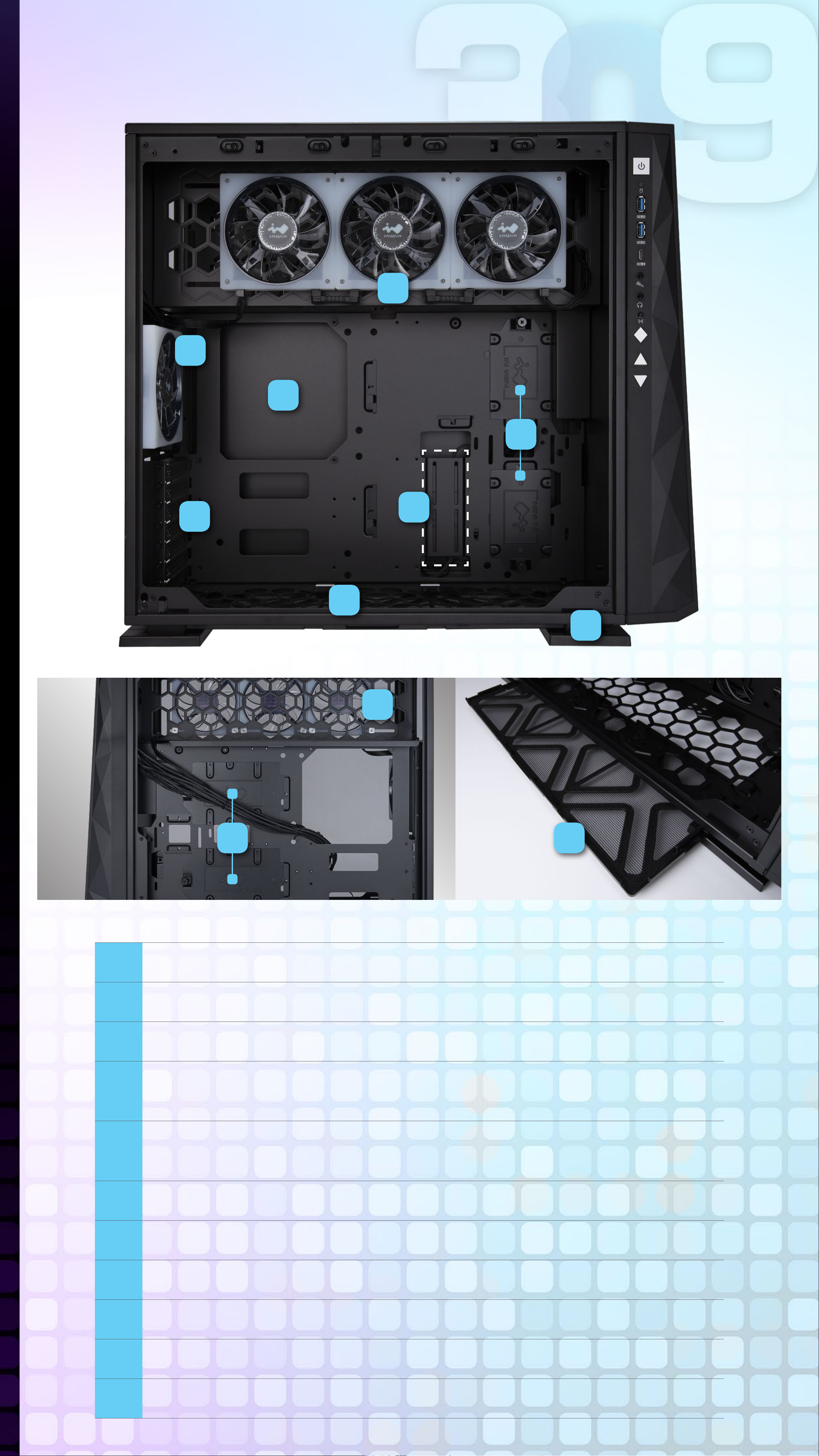
Case Structure
13
12
15
11
16
17
14
18
10
9
19
9 Power Supply Mounting Area
10 3.5" Drive Bay
11 2.5" Drive Bay
Top Fan / Radiator Mounting Area
12
(3 InWin EGO Fans Pre-Installed)
Rear Fan / Radiator Mounting Area
13
(1 InWin EGO Fan Pre-Installed)
14 Bottom Fan / Radiator Mounting Area
15 Motherboard Mounting Area
16 PCI-E Expansion Slots
17 Extra PCI-E Supporting Mounting Hole
18 Shock-Proof Stands
19 Fan Dust Filter
Page 9

Installation Guide
▪ Please follow the related chapters to assemble.
▪ Please use original provided accessories to avoid
damage to the product.
1
Opening the
Chassis
Please remove by
pressing the handle
on top of panel.
2
Clock Synchronization
Please pull the plastic mylar tab to
activate the clock synchronization,
then run the GLOW2 software to
Pull
provide accurate time on the front
panel.
3
Power Supply Installation
Parts Required:
Hexagon Head Screws
Power supply can be mounted on
the top bracket
Page 10

4
Motherboard
Installation
Parts Required:
Motherboard Stand-Offs,
Motherboard Stand-Off
Socket, Hexagon Head
Screws
5
Expansion Card
Installation
Parts Required:
Hexagon Head Screws,
Graphics Card Holder
Page 11

6
I/O Wires Installation
POWER SW
POWER LED
(Depend On Motherboard)
H.D.D LED
RESET SW
HD Audio Header
PORT2_L
SENSE_SEND
PORT2_R
BLUE
PURPLE
YELLOW
10
8
6
9
7
5
BROWN
WHITE
SENSE2_R
KEY
SNAS1_R
USB3.0 Header
PORT1_R
PORT1_L
RED
GREEN
4
2
PIN#1 PIN#19
3
1
ORANGE
BLACK
PRESENCE#
GND
Vbus
IntA_P1_SSRX-
IntA_P2_SSRX+
GND
IntA_P1_SSTX-
IntA_P1_SSTX+
GND
IntA_P1_D-
IntA_P1_D+
1
2
3
4
5
6
7
8
9
19
18
17
16
15
14
13
12
Vbus
IntA_P2_SSRXIntA_P2_SSRX+
GND
IntA_P2_SSTXIntA_P2_SSTX+
GND
IntA_P2_D-
ID USBOC-
PIN#10
10
11
PIN#11
IntA_P2_D+
Page 12

The Instructions of Type-C Cable
If your motherboard supports Type-C, please connect the
Type-C connector with the header directly on the motherboard.
Page 13

USB Cable
Please plug in USB port on motherboard.
LED Power
Ensure the beveled edge of the PSU connector is properly
aligned with the beveled edge of the LED light connector.
PSU Connector LED Light Connector
Red
Black
GND Black
12V Yellow
Controller Power
Make sure the PSU connector is properly aligned with the
controller connector from edge to edge.
PSU Connector
Controller Connector
Red
Black
GND Black
12V Yellow
Addressable RGB Cable (Optional Installation Steps)
If your motherboard supports the addressable RGB effect,
please follow the directions of the image below and insert
addressable RGB cable into the 3-pin, 5V header directly on
the motherboard.
Addressable RGB Connector
MotherBoard
Addressable
GND
Key
DATA
+5V
GND
Key
DATA
+5V
Page 14

4-Pin Fan Connector (Optional Installation Steps)
Please follow the directions of the image below and insert the
4-pin connector into the fan header directly on the motherboard.
Note: The fans will be controlled by the motherboard when the
connector is installed properly. If you would like to control
the EGO fans via InWin’s exclusive GLOW2 software,
please DO NOT install the fan connector with your
motherboard.
4-Pin Fan Connector
Ground
+12V
Tach
PWM
Fan
Motherboard
7
2.5” Drive Bays
Installation
Parts Required:
2.5” HDD Screws
8
3.5” Drive Bays
Installation
Parts Required:
3.5” HDD Screws
Page 15

9
Fan / Liquid
Cooling Radiator
Installation
Parts Required:
Water-cooling System
Washers, M3 / #6-32
Thread Water-Cooling
Radiator Screws
(EGO Exclusive)
10
Completing
Installation
Parts Required:
Cable Ties
Page 16

LED & Fan Control Buttons
Instructions
The LEDs and fans can be controlled by pressing the control
buttons on the I/O panel or controlled by GLOW2 software.
Control Buttons Descriptions
Control Mode
button
+
-
For more detailed
instructions, please
watch the video at this
website link
Control Buttons Instructions
Please follow the button sequence below to adjust LED
brightness, lighting effects and fan speed.
LED Lighting
Fan SpeedLED Brightness
Effects
Button Presses:
0 (Default)
Note: The control mode rotate to the LED Brightness
Mode if you press the Control Mode button three times.
Button Presses:
1
Button Presses:
2
Page 17

GLOW2 Software Instructions
The InWin exclusive GLOW2 software
encourages users to create their own unique
lighting effect. Choose your own style! The
simple and clean intuitive interface is easy
to operate. GLOW2 possesses 12 different
lighting modes, but the most intriguing is
Creation Mode, which grants users access to design their own
front panel to match their preferred theme. The only limitation is
your own imagination!
1. Please click “download” on 309 website to install the GLOW2
software. (https://www.in-win.com/en/gaming-chassis/309)
2. After downloading the GLOW2 on the desktop, please click
to open it.
Night ligh t
Vortex
Brightness
Candle SkyM usic
LED Speed
Twinklin gT ime tunnel E.C. G
Fan control
Bounce Cloc kH ourglass Creation
Software version 1.0.0
55 %
Data Source
Data transferring...
Page 18

1
2
3
4
1
2
3
4
Colors
Each mode provides up to 3 colors to choose from.
Twin klin g
Brightness
LED Spee d
Lights & Speed
Control lights and speed by + and - buttons,
there have 7 levels.
Fan control
55 %
EGO fans controlled
by GLOW2
EGO fans controlled
Fan Output
Control the EGO fans’ speed by pressing the + and
- buttons. There are 10 fan speed levels up to Turbo
mode. If the 4-pin fan connector is connected with
the motherboard, you can easily click the fan icon
on the GLOW2 software to adjust the control mode.
Note: The fan control will not work on the GLOW2
*
software if the motherboard software is running.
by motherboard
Data Source
The lighting effects
are controlled by
GLOW2 software
Motherboard or GLOW2 software options
Control the lighting effects with an ARGB enabled
motherboard. If your motherboard doesn’t have an
addressable header (3-pin, 5V), you can control the
lighting by downloading the GLOW2 software.
Note: The 309 and EGO fans use a lot of LEDs and some
*
motherboards may not be able to handle the number of
Data Source
LEDs. Please use the GLOW2 software if the lighting isn’t
functioning properly.
Addressable RGB header isn’t
properly connected to the
motherboard.
The lighting is controlled by
the motherboard software.
Data Source
Page 19

MIC Threshold Settings
Please set the numbers in ascending order. The smaller the
number, the greater the sensitivity.
Hourglass Time Setting
Please setting from 1 to 60 minutes.
* Note: Please click “Save to ROM” and “Apply” buttons to apply
all the changes.
Page 20

Mode Descriptions
Night Light
Create an atmosphere
in dark room
Candle
Lighting effect by voice catching
from microphone
Sky
Cloud oating in sky
Music
Equalizer mode’s lights
reveal the rhythm of music
Vortex
Rotating vortex
Twinkling
Like stars twinkling
in night sky
Time Tunnel
Dazzling tunnel effect
Bounce
E.C.G
Heartbeat effect by voice catching
from microphone
Time
Light moves like
bouncing ball
Hourglass
Clock display the time
Edit
Creation
Up to 60 minutes countdown.
Clap hand to reset the time when
red ash light shows time up.
Customize own
lighting effect
Page 21

Edit
Creation Mode
Creation
Customize own lighting effect
Tool
Brush / Eraser / File
Painting / Trash Can / Save
Palette
Please double-click the block to add/change
the colors.
SlideShow
Provide 4 plates to create image, which offer
60 second maximum to setting slideshow time
on front panel.
Page 22

Notices and Warranty
■ Notices
1. Please follow the user manual for installation.
2. To avoid damaging any circuits, please make
sure the power is off before assembling any
internal device.
3. When installing the computer components,
please use the antistatic precautions to prevent
ESD (electrostatic discharge) damage. This can
cause injury to the installer and/or damage to
the machine. Incorrect installation may burnout
the motherboard and other system components.
4. When the side panels are opened, please do
not put your hands or other objects into the fans
or other parts in operation. And please make
sure to keep away from children and pets.
5. Please avoid unnecessary insertions and
extractions to the addressable cable as it may
damage the pins.
6. To avoid any damages, please do not use this
product for any other purpose than its intended
use.
7. Any modifications may damage the product.
8. Please remove all internal devices before
shipping or moving. (Including power supply,
hard drives, motherboard, CPU, etc)
9. Keep this product away from areas with high
temperatures such as: heat dissipation
machines, air conditioners or other machines
which may generate high temperatures.
10. Please use only this product's exclusively
supplied cables. Other cables may not be
compatible and could cause serious damage to
your system and power supply.
Page 23

Notices and Warranty
■ Notices
11. Please replace the battery of the chip if the
clock synchronization doesn’t work.
12. There are 4 EGO fans pre-installed in this
product, if you would like to install 5 or more
fans, please use the additional exclusive power
cable to avoid overloading the system and
other system components.
■ Warranty
1. For more detailed warranty information, please
visit the InWin retail website at www.in-win.com.
2. The actual product is subject to change without
prior notice. InWin Development Inc. reserves
the right to make any final modifications.
Page 24

Copyright © 2019 In Win Development Inc. All Rights Reserved.
 Loading...