

Page 1

User Manual
Page 2
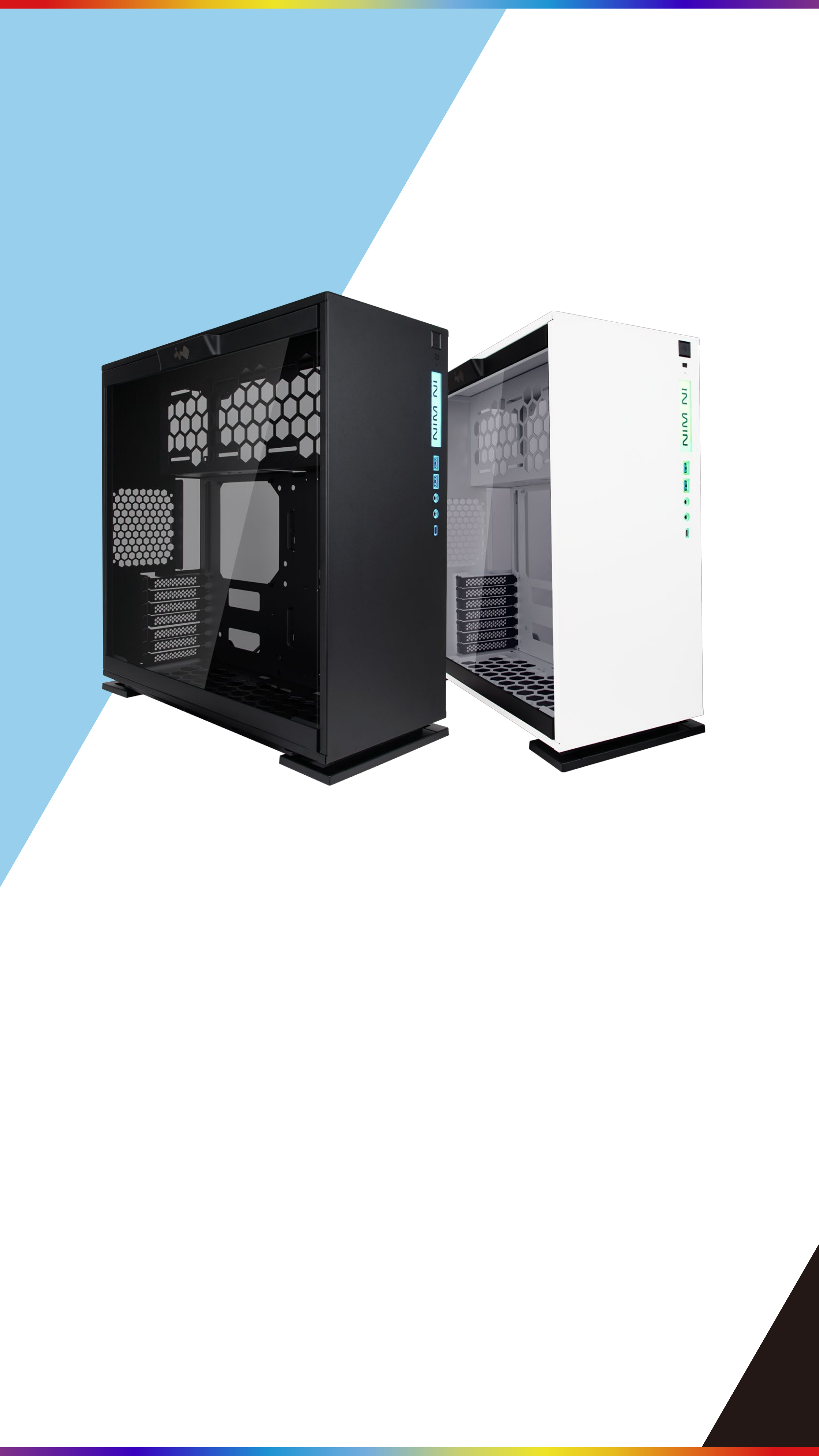
Product Story
The IN WIN team presents the 303C, a simple,
yet elegant computerchassis crafted from steel
and tempered glass.The distinctively cleanfront
panel is complemented with a bright LED
design to balance theoverall appearance.
While the 303C is a stunning visual display,
it’sbecause of the quality and skilled
engineering that pieced togethersuch a fine
piece of computer hardware.
Page 3

Specifications
Model
Color
Case Type
Material
M/B Compatibility
Expansion Slots
303C
Black, White
Mid Tower
Tempered Glass, SECC
12" x 10.7" ATX, Micro-ATX, Mini-ITX
PCI-E X 7
Maximum
Compatibility
Front Ports
Internal Drive Bays
VGA Card Length:350mm
CPU Heatsink Height :160mm
USB 3.1 Gen 2 Type-C
2 x USB 3.0
HD Audio
2 x 3.5"
Thermal Solution
Compatibility
Power Supply
2 x 2.5“ Pre-installed
(Max. up to 3 bays)
1 x 120mm Rear Fan / 120mm Radiator
3 x 120mm Top Fan / 360mm Radiator
3 x 120mm Bottom Fan
PSII: ATX12V
Compatibility
Product Dimension
(HxWxD)
Product Dimension
with screw & handle
height(HxWxD)
-Length: 200mm Maximum
500mm x 215mm x 480mm
19.6" x 8.4" x 18.8"
500mm x 248mm x 480mm
19.6" x 9.7" x 18.8"
Package Dimension
(HxWxD)
Net Weight
Gross Weight
■ In Win products comply with RoHS regulations
335mm x 610mm x 572mm
13.1" x 24" x 22.5"
10.96kg / 24lb
12.81kg / 28.2lb
■ Specifications may vary based on different regions
■ Pre-installed glass panel. Extra fee for closed panel
Page 4
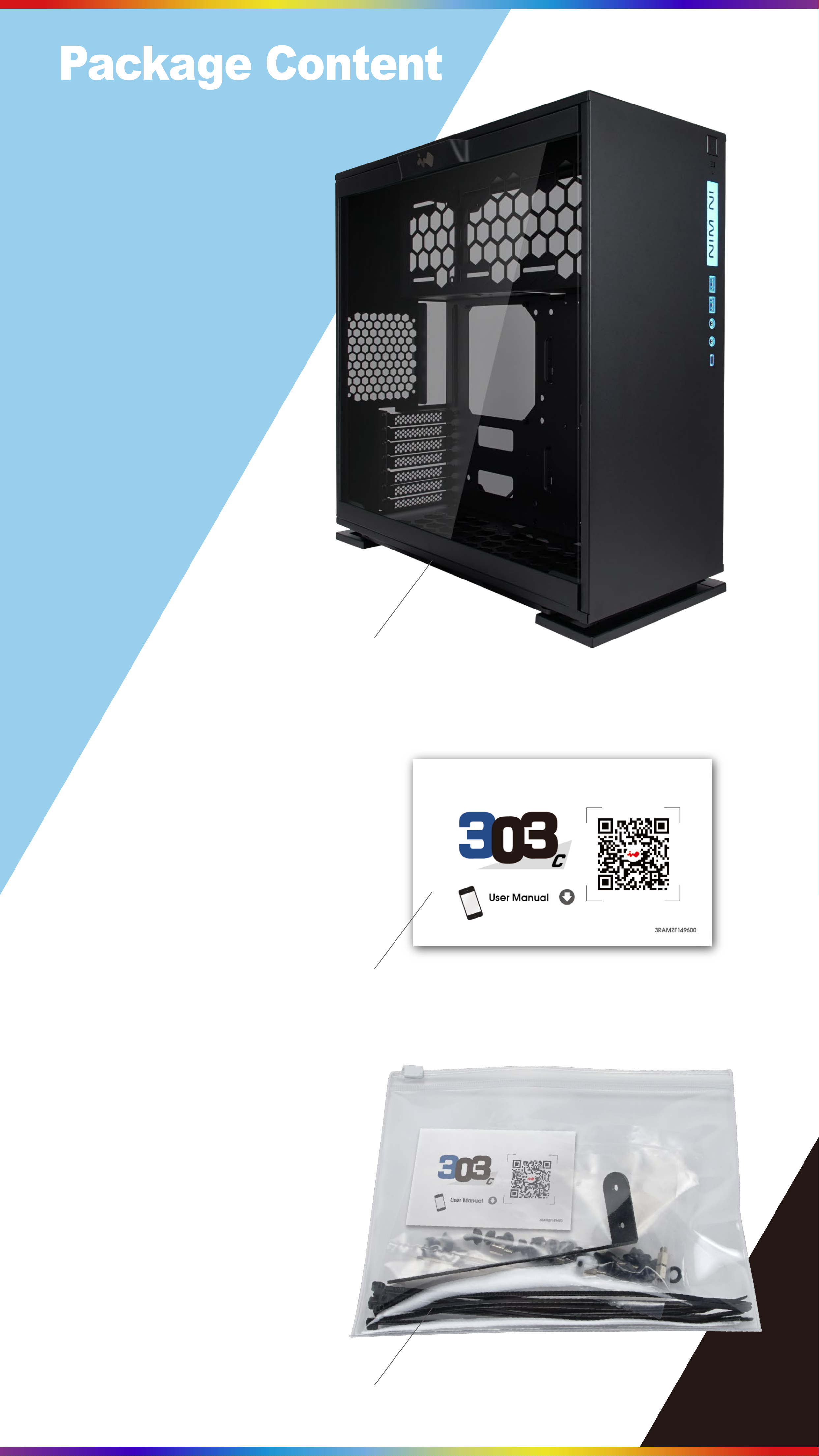
Package Content
303C Chassis
QR Code Card
Accessories Bag
Page 5

Accessories
Bag
Motherboard Stand-off X 7
Motherboard Stand-off Socket X 1
Hexagon Head Screws x 18
2.5” HDD Screws X 18
3.5” HDD Screws X 10
Water-cooling System Washer X 8
Cable Tie X 10
Graphics Card Holder x 1
Page 6
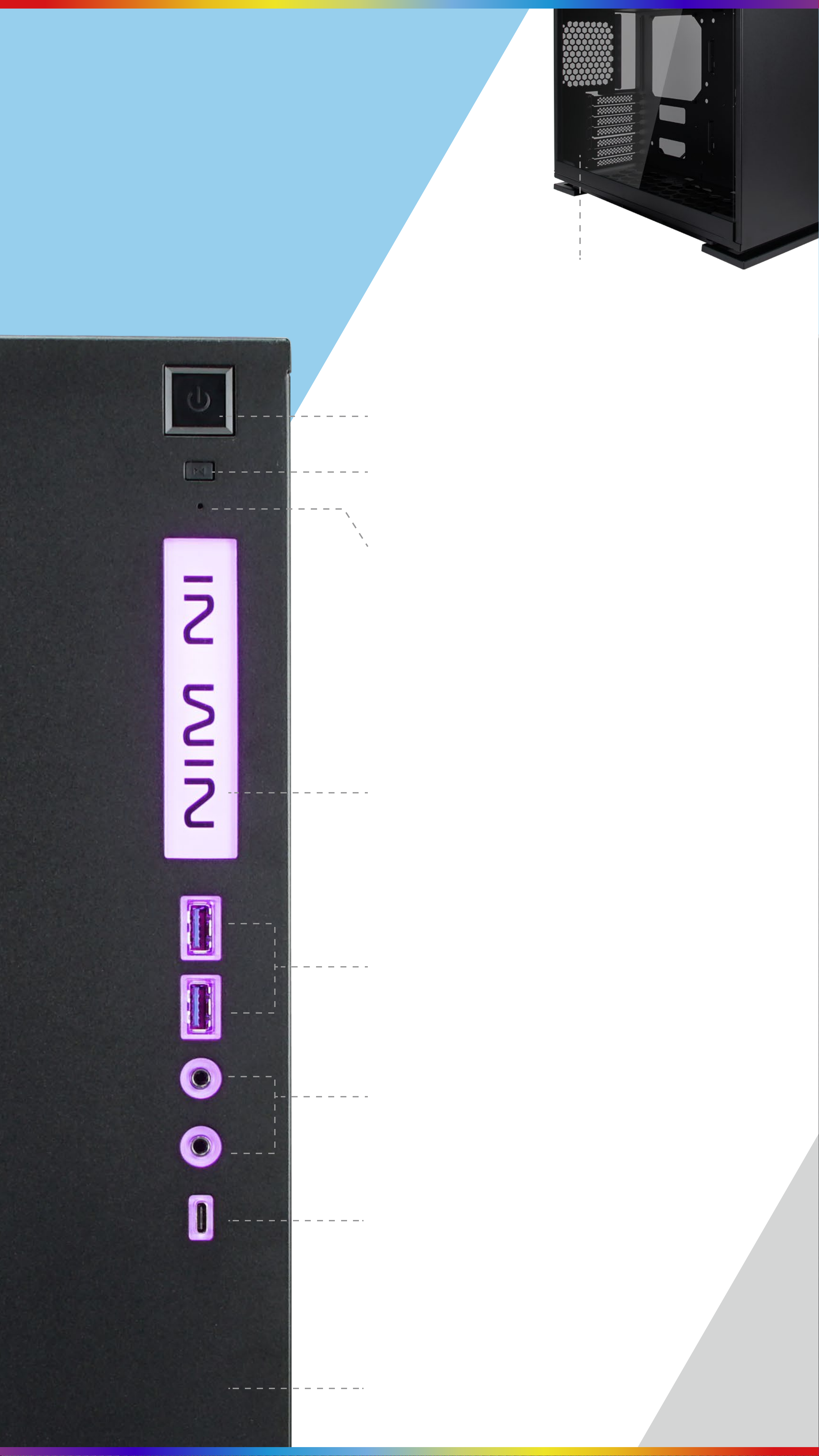
Case Structure
Tempered Glass
Power Button
Reset Button
HDD/Power LED Indicator
LED Logo
USB 3.0 Ports
Audio Ports
(Earphone and Microphone)
USB 3.1 Gen 2
Type-C Port
SECC Front /
Side Panel
Page 7

1
10
6
3
4
8
2
7
9
12
1
2
5
3.5” Drive Bay
2.5” Drive Bay
11
3
4
5
6
7
Top Fan/ Radiator Mounting Area
Rear Fan/ Radiator Mounting Area
Bottom Fan Mounting Area
Motherboard Mounting Area
CPU Cooler Installation Cut-Out Hole
8
9
10
11
12
PCI-E Expansion Slot
Extra PCI-E Supporting Mounting Hole
Power Supply Mounting Area
Fan Dust Filter
Shock-Proof Stand
Page 8

Installation Guide
(Please follow the related chapters to assemble)
1
Opening the Chassis
For Tempered Glass side panel, please
remove by pressing the handle on top
of panel.
2
Power Supply
Installation
Parts Required:
Hexagon Head Screws
Power supply can be mounted on the
top bracket.
3
Motherboard
Installation
Parts Required:
Motherboard Stand-Off,
Motherboard Stand-Off Socket,
Hexagon Head Screws
Page 9

4
Expansion Card Installation
Parts Required:
Hexagon Head Screws,
Graphics Card Holder
Page 10

5-1
RESET SW
POWER SW H.D.D LED
I/O Wires Installation
POWER LED
(Depend On Motherboard)
RESET SW
POWER SW H.D.D LED
POWER LED
HD Audio Header
POWER SW
RESET SW
Page 11

5-2
I/O Wires Installation
LED Pipe Power
Ensure the beveled edge of the PSU connector is properly
aligned with the beveled edge of the LED light connector
PSU Connector LED Light Connector
USB3.0 Header
Page 12

6-1
The Instructions of RGB-Strip
If your motherboard support the RGB luminous effect,
please follow the direction of sign and insert RGB-strip
into the 4-pin RGB-strip header directly on the motherboard.
Page 13

6-2
The Instructions of Type-C Cable
If your motherboard supports Type-C, please connect the Type-C
connector with the header directly on the motherboard.If your
motherboard supports Type-C, please connect the Type-C connector
with the header directly on the motherboard.
Page 14

7-1
2.5” Drive Bays Installation
Parts Required: 2.5” HDD Screws
7-2
3.5” Drive Bays Installation
Parts Required: 3.5” HDD Screws
8
Fan / Liquid Cooling Radiator
Installation
Parts Required: Fan Screws,
Water-cooling System Washer
Page 15

9
Bottom Fan Installation
*Please remove the rubber foot stands,
and then loosen the screws on top.
10
Completing Installation
Parts Required: Cable Ties
Page 16

Notices and Warranty
■ Notices
1. Please follow the user manual for installation.
2. When installing the computer components,
please use the antistatic precautions to prevent
ESD (electrostatic discharge) damage. This can
cause injury to the installer and/or damage to the
machine. Incorrect installation may burn
motherboard and other system components.
3. To avoid any damages, please do not use this
product for any other purpose than its intended use.
4. Any modifications may damage the product.
5. Please remove all internal devices before shipping
or moving. (Including power supply, hard drive,
CD-ROM, motherboard and CPU, etc)
■ Warranty
* For more detailed warranty information, please
visit In Win retail website at www.in-win.com.
* The actual product is subject to change without
prior notice. In Win Development Inc. reserves
the right to make final modifications.
Page 17

Copyright © 2017 In Win Development Inc. All Rights Reserved.
 Loading...