

Page 1

High Security 200
Handheld & Tablet Power-Up + Alarm Installation
MP602
Page 2
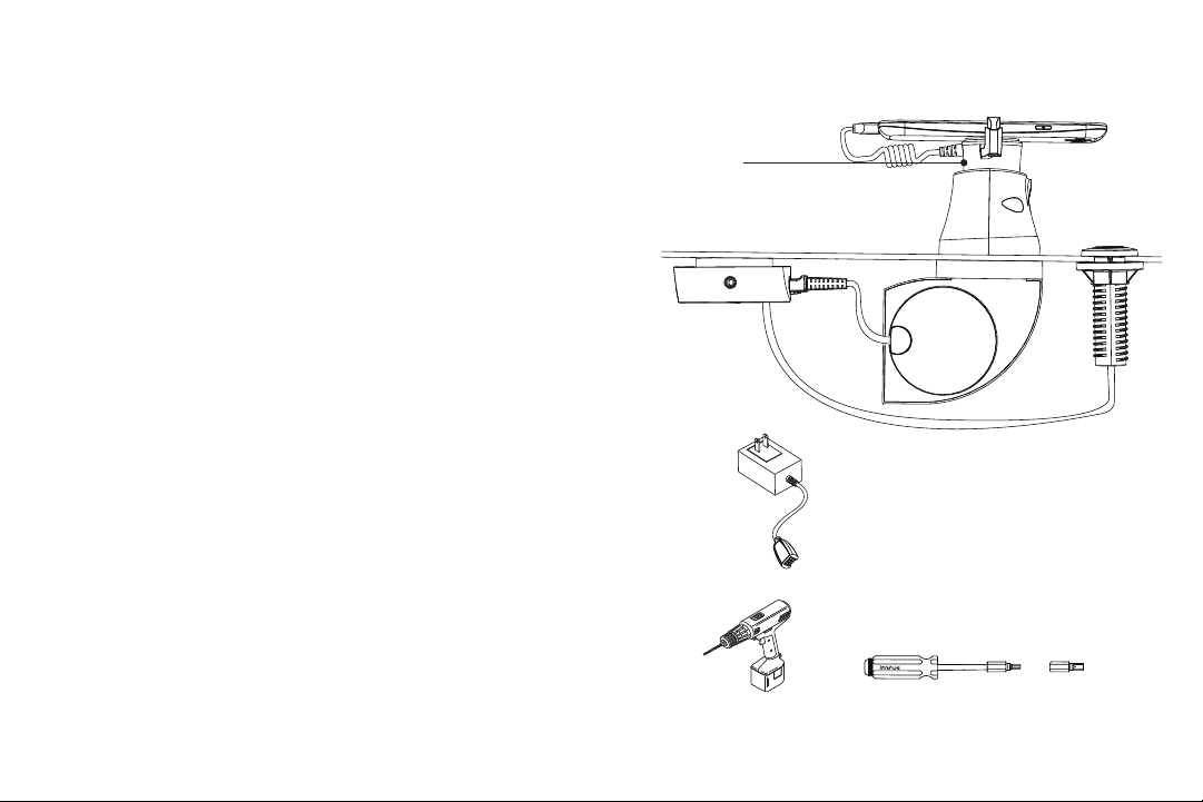
Read entire instruction guide before starting installation.
5
10
20
30
System Components
1. HS200 Alarming Recoiler (MP602)
2. Handheld Alarm Unit (MP100) or Tablet Alarm Unit
(M P 101)
3. HS200 Handheld or Tablet Sensor
4. Puck (MP217, MP218)
5. IR Dot (MP207)
Sensor
MP609
MP610
MP611
MP612
MP613
MP614
Puck
MP217
MP218
IR Dot
MP207
6. 18V Power Supply
7. IR Key (not included)
System Overview
HS200 is designed to provide high security for high risk
environments. This system provides tough mechanical
Alarm Unit
MP100
MP101
HS200
Alarming
Recoiler
MP602
security combined with alarming security and regulated
device power-up ability.
18V Power Supply
PS18VUS
PS18VEU
PS18VAUS
PS18VUK
PS18VARG
T-20 Bit
(included with
Multi Tool)
2 3
Drill Multi Tool
AF6313
T-27 Bit
(included with
Multi Tool)
Page 3
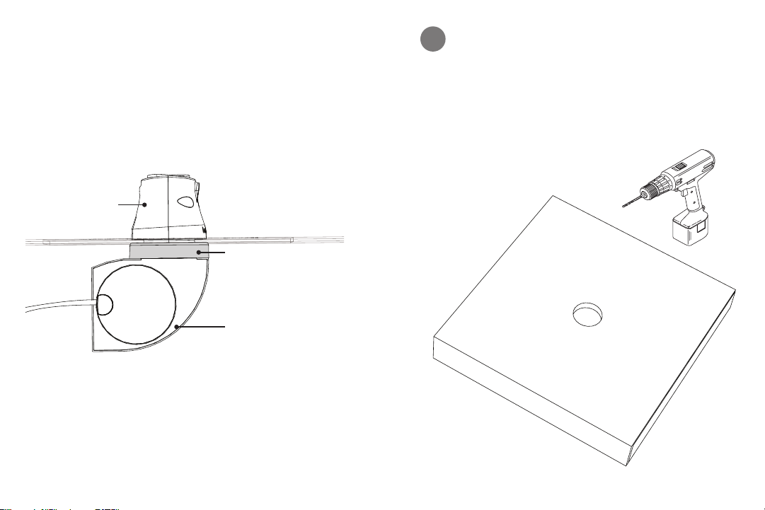
RECOILER & PUCK INSTALLATION
Puck
Spacer
(For display counters
between 3.175 mm, 0.125”
and 12.7 mm, 0.5” thick.)
Recoiler
Drill a 45 mm (1.75”) diameter hole in display
1
counter.
30
20
10
5
4 5
Page 4
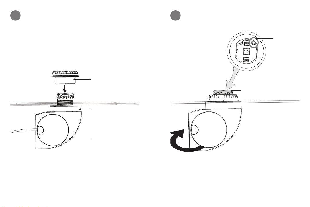
Slide recoiler up through hole in display counter. Use
2a
spacer if needed. Loosely hand tighten cap above
counter onto recoiler.
Cap
Spacer
(For display counters
between 3.175 mm, 0.125”
and 12.7 mm, 0.5” thick.)
Recoiler
Rotate recoiler until cut out in recoiler is towards back
2b
of display counter. Fully tighten cap.
Front of
display
counter
Recoiler
Cut out in
recoiler
Back of
display
counter
6 7
Page 5
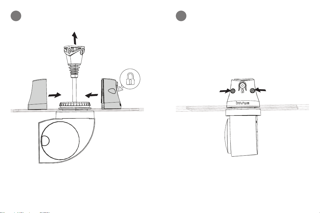
Pull recoiler up and slide both parts of puck together
3a
on cap. Confirm lock is at back of display counter.
Fully tighten screws on puck with T-20 bit.
3b
Front of
display
counter
8 9
Back of
display
counter
Page 6
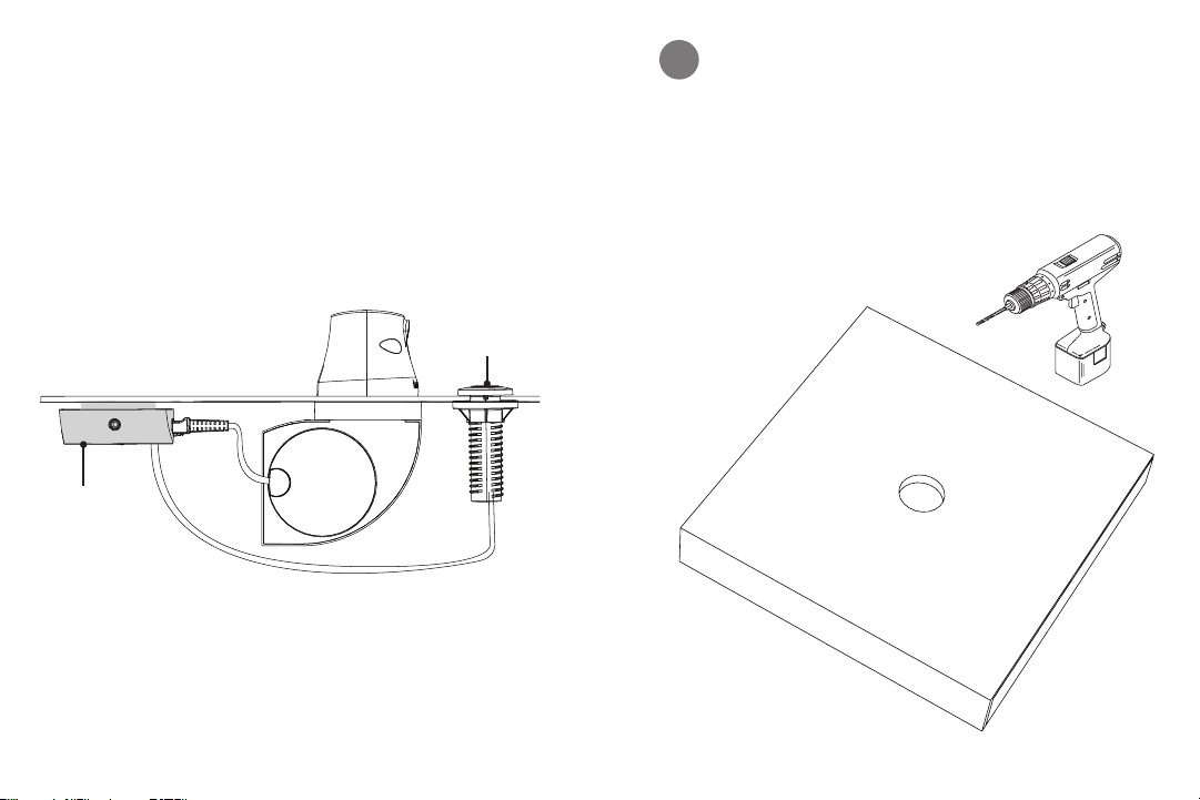
ALARM & IR DOT INSTALLATION
Alarm Unit
IR Dot
Drill a 20.5 mm (0.8125”) diameter hole in display
1
counter at preferred location for IR Dot.
30
20
10
5
10 11
Page 7
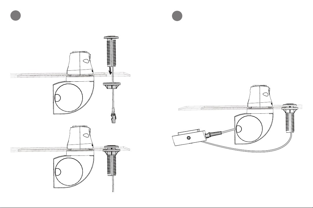
Slide IR dot through display counter and tighten
2
nut below counter.
Plug cord from recoiler and IR dot into alarm unit.
3
12 13
Page 8
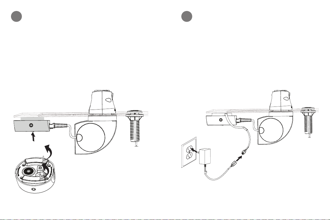
Remove clear film from Alarm Unit. Attach Alarm Unit
4 5
below counter near puck. Press firmly for at least 10
seconds.
Plug cord from alarm unit into power supply. Plug
power supply into outlet.
14 15
Page 9
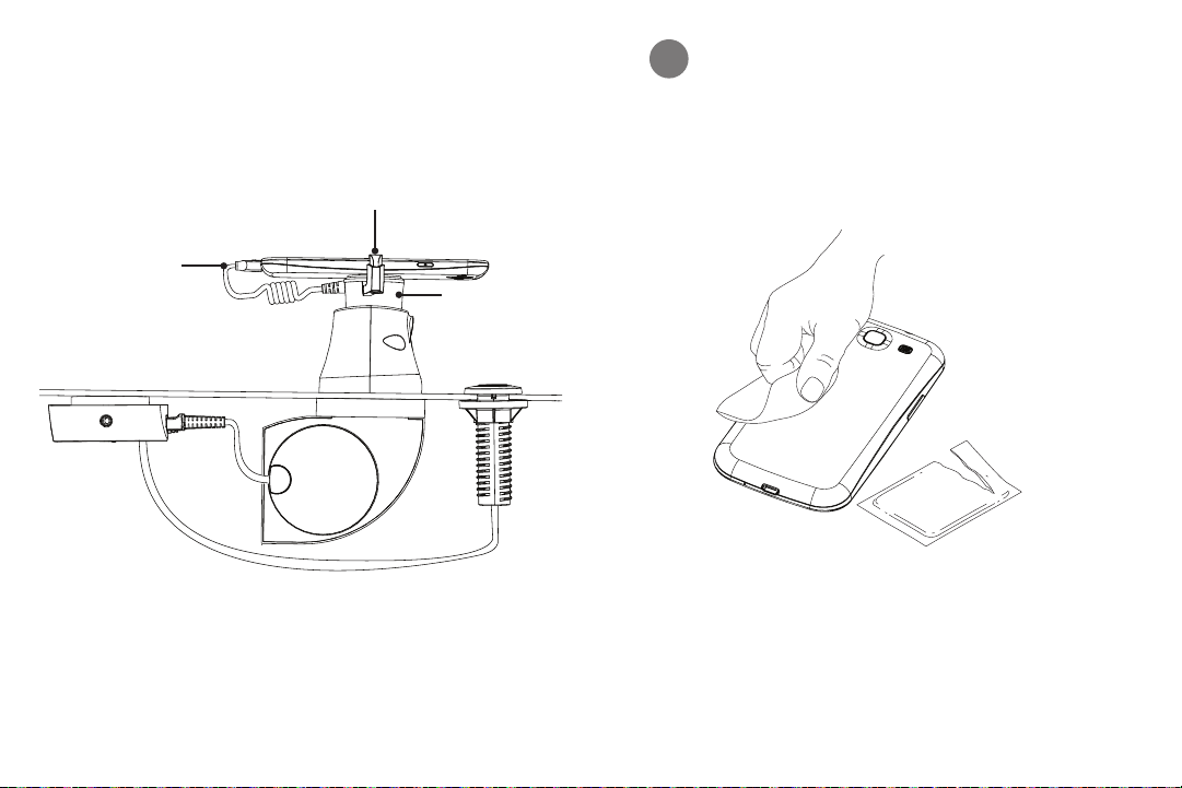
ATTACHING MERCHANDISE
Power
Connector
Arms
Sensor
Wipe back of phone with alcohol wipe provided. Let it
1
dry completely.
CONTENTS: One pad saturated in
Isopropyl Alcohol
FOR EXTERNAL USE ONLY
KEEP OUT OF REACH OF
CHILDREN
75%
KEEP AWAY FROM EYES
DIRECTIONS: Apply topically as
needed to cleanse surface mounting area.
AND FIRE
16 17
Page 10
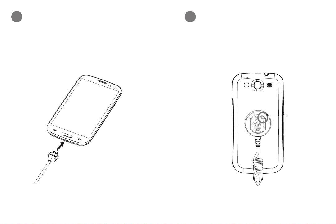
Plug power connector into phone.
2 3
Confirm phone is placed on sensor correctly so orientation of phone is correct on recoiler. Make sure cut out
in sensor is towards top of phone.
Top of Phone
Cut out in
sensor
18 19
Page 11
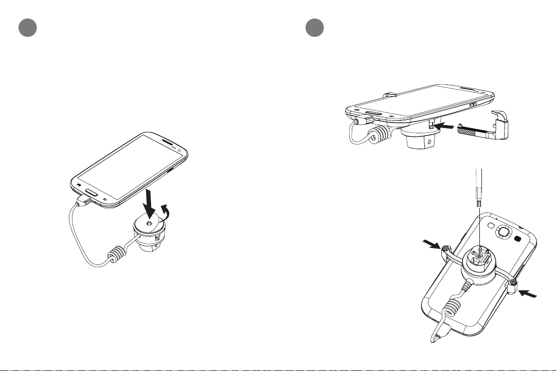
Remove clear film off adhesives on sensor. Center and
4
attach merchandise to sensor. Press firmly for at least
10 seconds.
Attach both arms to sensor. Confirm arms are fitted
5
to width of merchandise. Squeeze both arms against
merchandise and tighten screw with T-20 bit to lock
arms in sensor.
20 21
Page 12
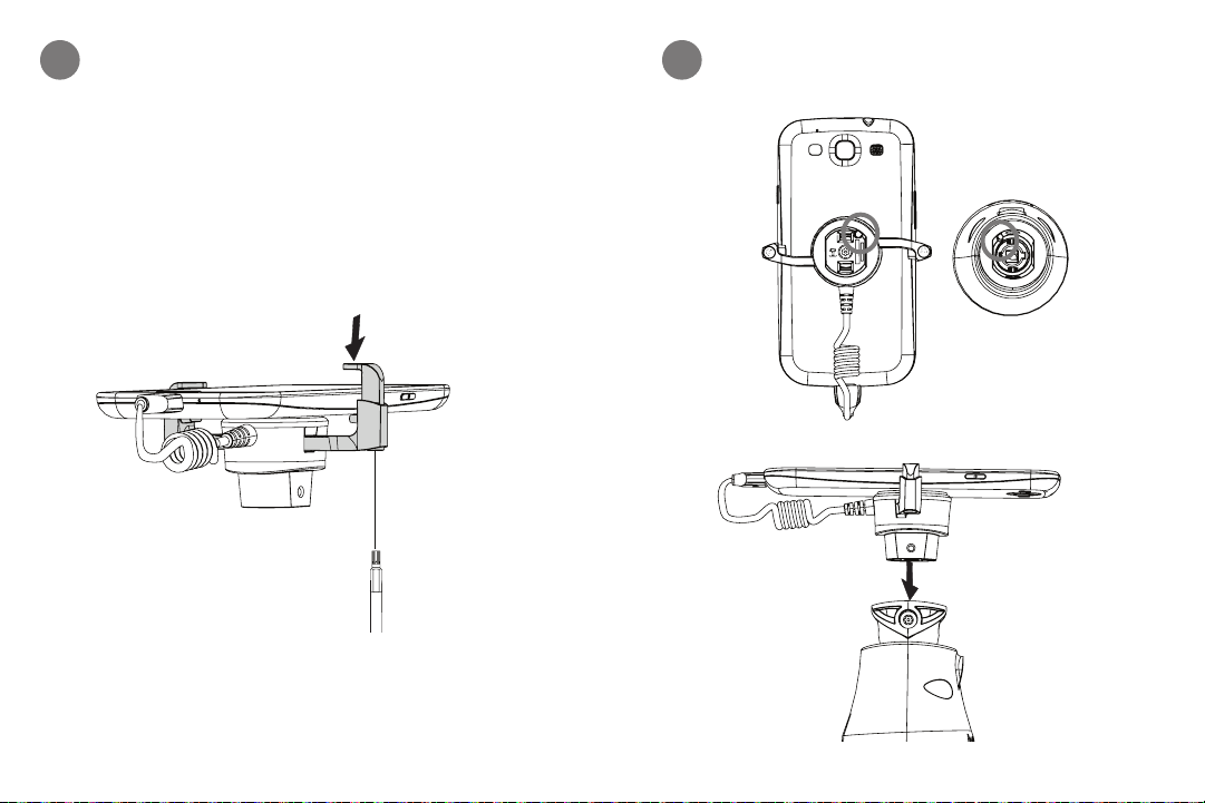
Adjust arms to thickness of merchandise and tighten
6
screw with T-20 bit. Do not overtighten.
Attach sensor to recoiler.
7
22 23
Page 13
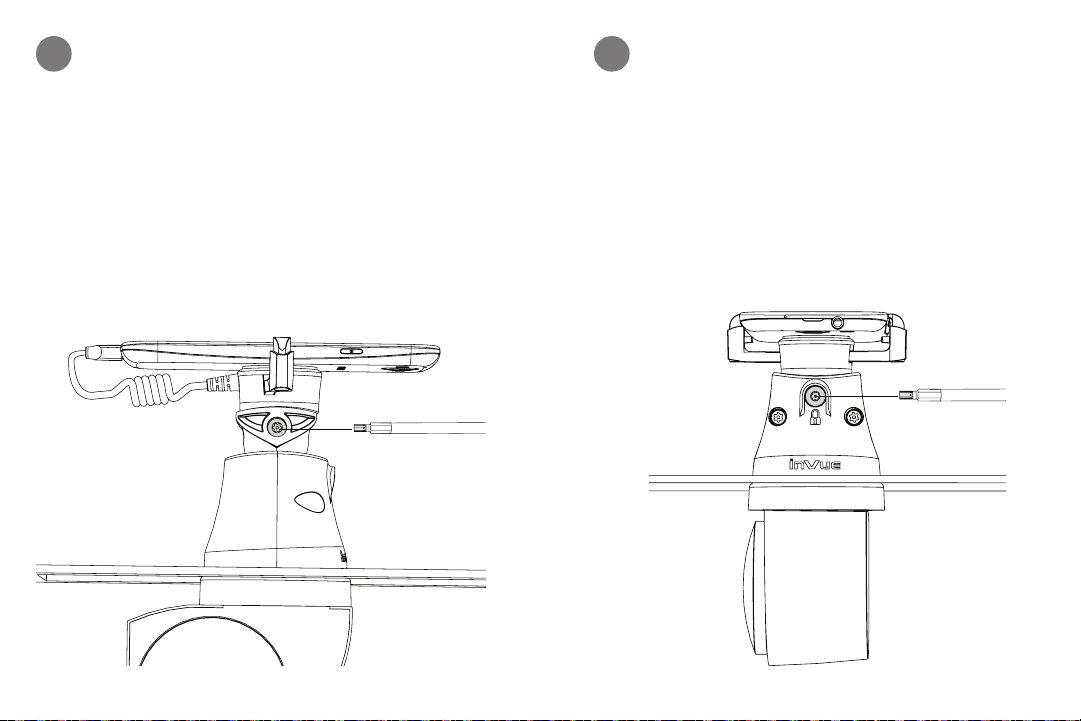
Fully tighten both screws with T-20 bit.
8
Optional. Lock screw with T-27 bit to prevent from
9
lifting recoiler.
24 25
Page 14
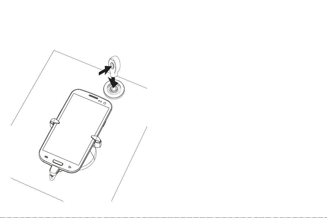
Arm/Disarm Alarm
Place key on lens of IR Dot.
Press grey button once to
arm and disarm alarm.
26
Page 15

SD0145 Rev0 0 3/06/13
www.invuesecurity.com
Corporate Office (North America) // 704.752 .6 513 • 888.55.INVUE
Europe, Middle East & Africa // + 31. 23 .8 9 00150
Asia Pacific // +65.6766.4844
Latin America // +52.55.9000.3957
© 2013 InVue Security Products Inc. All rights reserved.
InVue is a registered trademark of InVue Security Products.
 Loading...