

Page 1
!
Samsung S-Pen Tray Recoiler
Installation Guide
Please read the entire guide before beginning the installation and follow all steps as
described. Please keep this manual for future reference.
A
B
System
Components:
!
CAUTION!
DNAZ85
Custom S-Pen
Tray Non-Alarming
Display
Qt y. 1
Assembled Stylus
Clip
Qt y. 1
24 hours is required for all adhesives to completely cure and reach full adhesive strength.
Please do not use the products immediately after the placement of the adhesive.
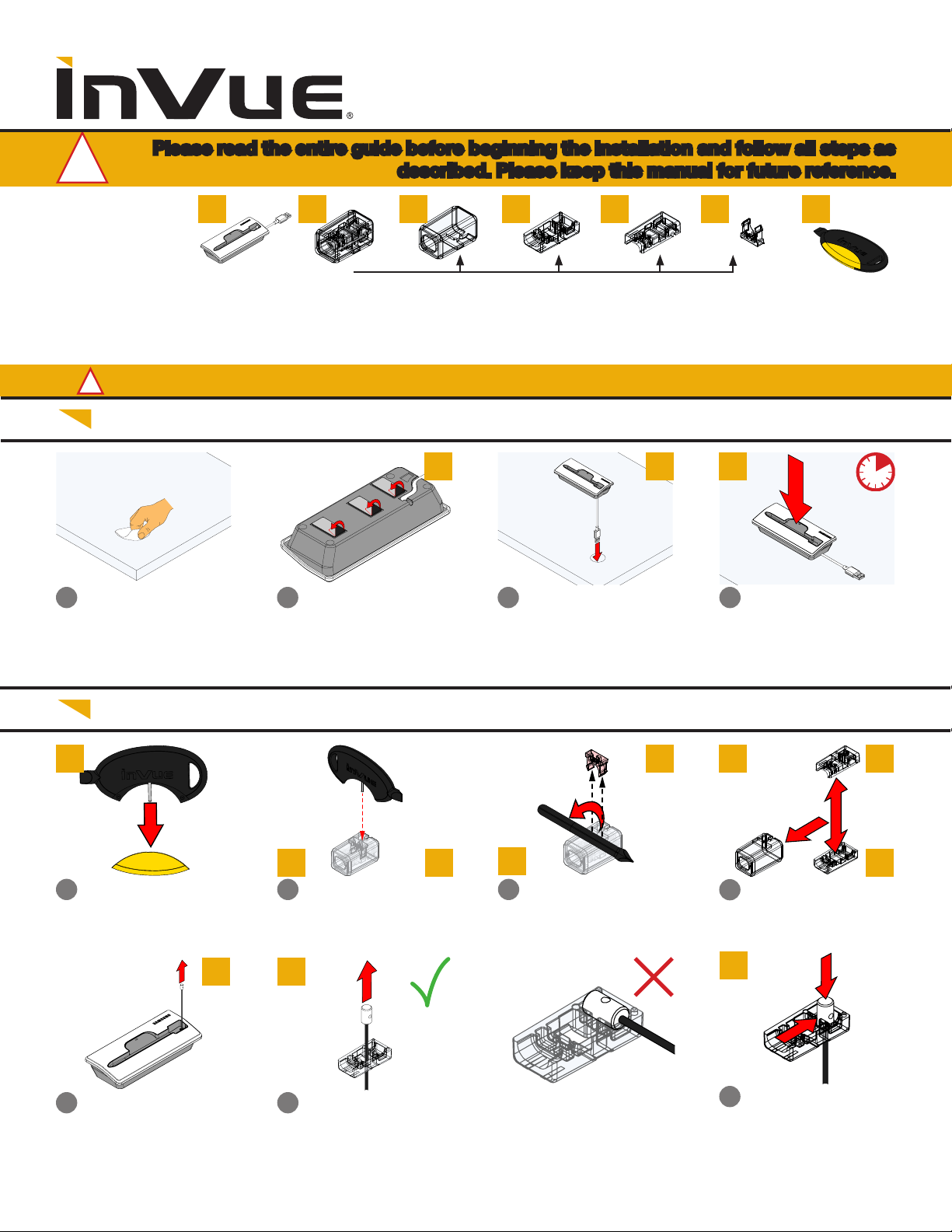
Part 1: Recoiler Installation
Clean the xture with the
1
alcohol wipe provided.
Let it dry completely.
Peel the liners from the
2
adhesives on the bottom of
the recoiler.
C D E G
Outer Sleeve
Qt y. 1
A A
Bottom Stylus Clip
Piece
Qt y. 1
Optional:
3
If desired, route the cable
through a hole or slot in the
xture.
Top Stylus Clip
Piece
Qt y. 1
A
F
Retainer
Qt y. 2
4
Place the recoiler in the
desired location and apply
pressure for at least 10
seconds.
Key Fob Tool
Qt y. 1
Part 2: Tether Installation
G
B
Remove the pin cover from
5
the fob tool.
Pull the tether from the
8
recoiler.
A C
Insert the pin into the hole
6a
opposite of the cable.
Insert the end of tether through the hole in the bottom stylus piece. Do NOT
9a
lay it down in the cavity.
G
B
Pivot the fob tool back to
6b
remove the retainer.
Note: Be careful not to lose
the clip when removing.
F
C D
E
Remove the sleeve and
7
separate the upper and lower
halves of the stylus clip.
C
Slide the tether end back and
10
place it in the depression on
the inside of the bottom stylus
piece.
Page 2
C
C
Cable
Gap
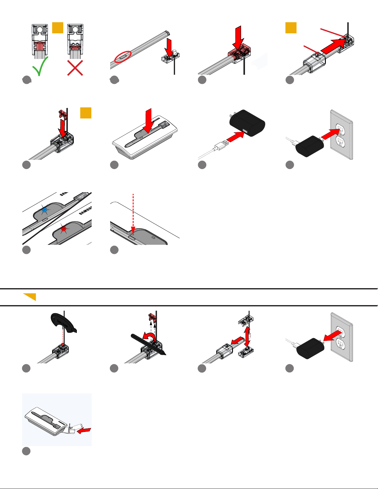
Prepare the stylus for
11a
installation into the clip by
making sure that it is clicked
open.
Insert the retainer into the
14
hole on the sleeve cover and
through the bottom piece of
the clip. It should sit ush
when properly assembled.
When docked, the LED on
18
the tray will illuminate Blue
to indicate that the S-Pen is
charging. It will change to Red
when the S-Pen is lifted or is
not charging properly.
With the S-Pen clicked open,
11b
place it into the cavity of the
bottom stylus clip piece. The
button on the S-Pen should
face upwards.
Place the top half of the stylus
12
clip over the S-Pen.
Orient the sleeve cover so
13
that the gap will align with the
cable. Slide the cover up the
length of the S-Pen and over
the 2 pieces of the stylus clip
F
Place the S-Pen into the
15
display.
If the S-Pen loses Bluetooth
19
connection with the device,
insert a small pin tool (such
as a paper clip) into the
hole to press the button to
reestablish the connection.
Make sure that the S-Pen is
correctly docked in the tray.
Plug the power cable into a
16
power supply.
Plug the power supply into a
17
power outlet.
Part 3: Removal
Insert the pin fob tool into the
1a
hole next to the cable.
Use the scraper removal
4
tool (DNTX93) to break the
adhesive bond between the
recoiler and xture.
Pivot the fob tool back to
1b
remove the retainer.
Note: Be careful not to lose
the clip when removing.
Slide the sleeve off the pen
2
and separate the upper and
lower halves of the stylus clip.
Unplug the power supply from
3
the outlet.
Page 3
PMN: CUSTOM TRAY S PEN DISPLAY
FCC ID: 2AFR8F1754A
IC: 23313-F1754A
FCC WARNING STATEMENT
This device complies with part 15 of the FCC Rules. Operation is subject to the following two conditions: (1) This device may not cause harmful interference, and (2) this device must accept any
interference received, including interference that may cause undesired operation.
This device complies with Part 18 of the FCC rules.
NOTE: This equipment has been tested and found to comply with the limits for a Class B digital device, pursuant to Part 15 of the FCC Rules.
These limits are designed to provide reasonable protection against harmful interference in a residential installation. This equipment generates, uses and can radiate radio frequency energy and, if not
installed and used in accoradance with the instructions, may cause harmful interfernce to radio communications. However, there is no guarantee that interference will not occur in a particular
installation. If this equipment does cause harmful interference to radio or television reception, which can be determined by turning the equipment off and on, the user is encouraged to try to correct
the interference by one or more of the following measures:
• Reorient or relocate the receiving antenna.
• Increase the separation between the equipment and receiver.
• Connect the equipment into an outlet on a circuit different from that which the receiver is connected.
• Consult the dealer or an experienced radio/TV technician for help.
FCC RADIATION EXPOSURE STATEMENT
(Wireless Charger Dock)
This equipment complies with FCC Radiation exposure limits set forth for an uncontrolled environment. This device and its antenna must not be co-located or operating in conjunction with any other
antenna or transmitter. This equipment should be installed and operated with a minimum distance of 15 cm surrounding the device and 20 cm above the top surface of the device.
IC WARNING STATEMENT
This device complies with Industry Canada licence-exempt RSS standard(s). Operation is subject to the following two conditions: (1) this device may not cause interference, and (2) this device must
accept any interference, including interference that may cause undesired operation of the device. Le présent appareil est conforme aux CNR d’Industrie Canada applicables aux appareils radio exempts
de licence. L’exploitation est autorisée aux deux conditions suivantes : (1) L’appareil ne doit pas produire de brouillage, et (2) L’utilisateur de l’appareil doit accepter tout brouillage radioélectrique subi,
même si le brouillage est susceptible d’en compromettre le fonctionnement.
IC RADIATION EXPOSURE STATEMENT
(Wireless Charger Dock)
This equipment complies with IC RF Radiation exposure limits set forth for an uncontrolled environment. This device and its antenna must not be co-located or operating in conjunction with any other
antenna or transmitter. This equipment should be installed and operated with a minimum distance of 20cm between the radiator and your body. Cet équipement est conforme aux limites établies par
Industrie Canada en matière d’exposition aux radiofréquences dans un environnement non contrôlé. Cet appareil etson antenne ne doivent pas être colocalisés ou fonctionner en conjonction avec tout
autre antenne ou émetteur. Cet équipement doit être installé et utilisé avec une distance minimale de 20cm entre le radiateur et votre corps.
WARRANTY - APPLICABLE TO ALL PARTS SHOWN
InVue warrants that if, within one (1) year of purchase, should there be a defect in material or workmanship,
and if, in the judgment of InVue, the product has received normal use and care, and if no damage or wear
has resulted from abuse, neglect, misuse, tampering, or accident, the product will be repaired or replaced
free of charge, as determined by InVue in its sole discretion. All claims of defects shall be made in writing
no later than ten (10) business days after discovery thereof. THIS WARRANTY IS MADE IN LIEU OF ALL
WARRANTIES OF MERCHANTABILITY AND FITNESS FOR PURPOSE. ALL OTHER WARRANTIES ARE
EXCLUDED. The product is not a sale of consumer goods and is for commercial or business use only.
INVUE’S ONLY OBLIGATION SHALL BE TO REPAIR OR REPLACE SUCH PRODUCTS PROVED TO BE DEFECTIVE. INVUE SHALL NOT IN ANY WAY BE LIABLE EITHER IN TORT OR IN CONTRACT FOR ANY LOSS
OR DAMAGE, DIRECT OR INCIDENTAL, OR CONSEQUENTIAL, ARISING OUT OF THE USE OR INABILITY
TO USE THE PRODUCTS. IN NO EVENT SHALL INVUE’S LIABILITY EXCEED THE PURCHASE PRICE OF
ANY PRODUCT.
www.invue.com
For after sale service, please see contact information below for
InVue Customer Support globally or visit our website here.
If you encounter an issue accessing the link for VOC or A/S,
please try https://invue.com/contact-information.
When registering the VOC or A/S request, please describe the
symptom or issue as clearly as possible.
NA / L ATAM // 704.752.6513 • 888.55.INVUE
EMEA // +31.23 .8900150
APAC // +852.3127.6811
SD06 99 Rev8 10/21/19
 Loading...