

Page 1
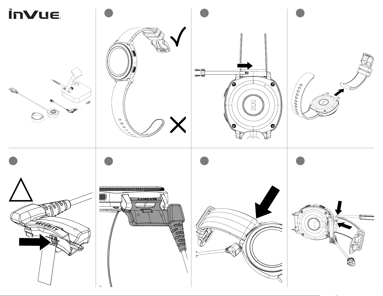
Samsung W1000
Use the pin removal tool to
Band Sensor Installation:
Stand with Quick Connect - DVW110
Quick Connect Sensor - DVW220/230
Custom Charge Head - DVW440
1
Select the watch band with the
buckle.
2
disengage the watch pin.
Remove the watch band from the
3
watch body.
Inspect the sensor to make sure
4a
that the tape on the sensor is intact
and that the switch is in the down
position.
!
2
1
Align the sensor with the watch body
4b
as shown. Make sure that the tape
on the sensor ts between the sensor
and the watch body.
With the sensor held in place against
5
the watch body, reinsert the side of the
watch band without the pin into the
watch body.
Use the tool or a ngernail to depress
6
the other pin and insert that side into
the watch body.
Page 2

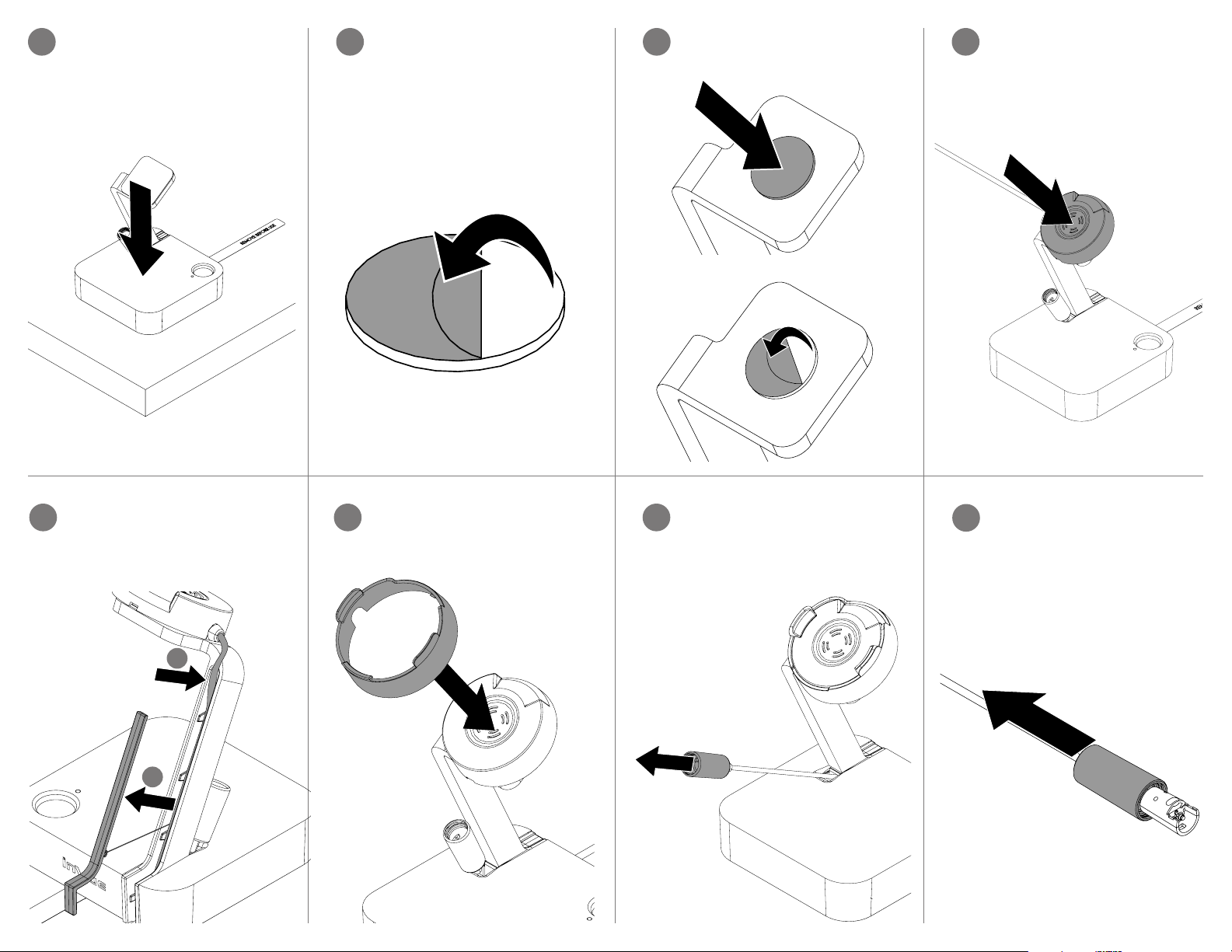
Pull the tape from the sensor to
Gently tug the watch band to make
7
the other side of the pin and pivot the
clean the surface where the stand will
sure it is secured.
8
activate the alarm
Use the pin removal tool to
9
disengage the pin on the other band.
Remove the watch band from the
10
watch body.
Orient the band clip so that the at
11
side of the clip will sit along the top
side of the band.
Flat Side
Slide the clip over the band from the side
with the pin.
Use the pin removal tool to push in
12
band into place.
Stand Installation:
13
Use the provided alcohol wipe to
be placed. Allow it to dry completely.
Peel the liner from the adhesive on
14
the bottom of the stand.
Page 3
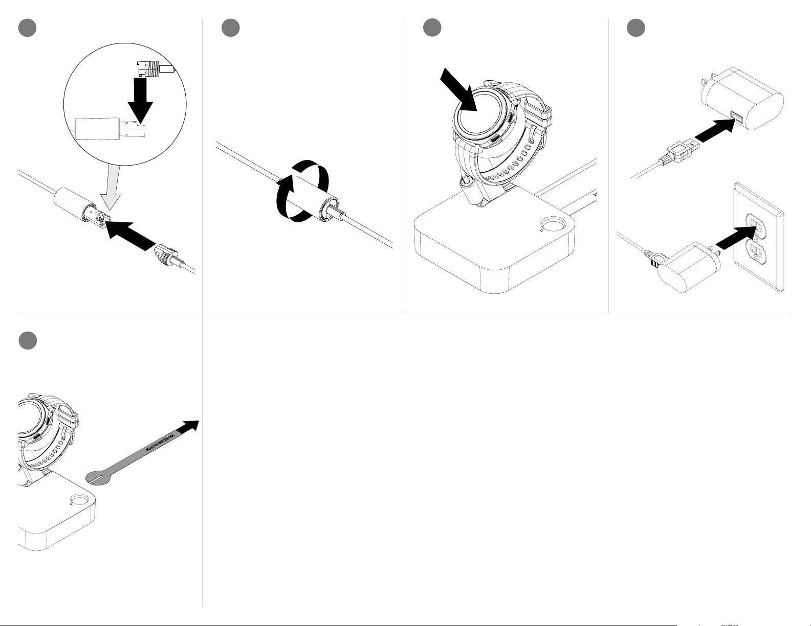
Place the stand in the desired
onto the adhesive. Apply pressure for
stem and route the charger cable into
Peel the liner from the adhesive.
15
location and apply pressure for at
least 10 seconds.
Charger Installation:
16
Peel the backing from the circular
adhesive.
Place the adhesive on the end of the
17
stand’s arm. Apply pressure for at
least 10 seconds.
Orient the charger with the cable
18
facing towards the stem and place
at least 10 seconds.
Remove the cable cover from the
19
the channel as shown. Replace the
cable cover to its original position to
hold the cable in place.
2
1
Snap the cover onto the charger.
20
Pull the quick connect adapter from
21
the unit.
To connect the sensor head, pull
22
back the barrel on the recoiler cable.
Page 4
Insert the sensor end into the barrel
Twist the barrel over the sensor
reversed, be sure that the threads are
Plug the charger cable into the power
supply. Plug the power supply into an
23
on the recoiler cable.
24
connection to secure.
Note: The internal threads are
fully engaged when tightening.
Place the watch and sensor onto the
25
charger.
26
outlet. Make sure that the watch is
receiving power.
Pull the battery tab to alarm the unit.
27
FCC WARNING STATEMENT
FCC Part 15.19 This device complies with part 15 of the FCC Rules. Operation is subject to the following two conditions: (1) this device may not cause harmful interference, and (2) this device must accept any
interference received, including interference that may cause undesired operation. FCC Part 15.21 Any changes or modications (including the antennas) to this device that are not expressly approved by the
manufacturer may void the user’s authority to operate the equipment.
FCC RADIATION EXPOSURE STATEMENT
(Wireless Charger Dock)
This equipment complies with FCC Radiation exposure limits set forth for an uncontrolled environment. This device and its antenna must not be co-located or operating in conjunction with any other antenna or
transmitter. This equipment should be installed and operated with a minimum distance of 20cm between the radiator and your body.
IC WARNING STATEMENT
This device complies with Industry Canada licence-exempt RSS standard(s). Operation is subject to the following two conditions: (1) this device may not cause interference, and (2) this device must accept
any interference, including interference that may cause undesired operation of the device.Le présent appareil est conforme aux CNR d’Industrie Canada applicables aux appareils radio exempts de licence.
L’exploitation est autorisée aux deux conditions suivantes : (1) l’appareil ne doit pas produire de brouillage, et (2) l’utilisateur de l’appareil doit accepter tout brouillage radioélectrique subi, même si le brouillage
est susceptible d’en compromettre le fonctionnement.
Under Industry Canada regulations, this radio transmitter may only operate using an antenna of a type and
maximum (or lesser) gain approved for the transmitter by Industry Canada. To reduce potential radio nterference to other users, the antenna type and its gain should be so chosen that the equivalent
isotropically radiated power (e.i.r.p.) is not more than that necessary for successful communication. Conformément à la réglementation d’Industrie Canada, le présent émetteur radio peut fonctionner avec une
antenne d’un type et d’un gain maximal (ou inférieur) approuvé pour l’émetteur par Industrie Canada. Dans le but de réduire les risques de brouillage radioélectrique à l’intention des autres utilisateurs, il faut
choisir le type d’antenne et son gain de sorte que la puissance isotrope rayonnée équivalente (p.i.r.e.) ne dépasse pas l’intensité nécessaire à l’établissement d’une communication satisfaisante.
IC RADIATION EXPOSURE STATEMENT
This equipment complies with the ICES RF radiation exposure limits set forth for an uncontrolled environment. This equipment should be installed and operated with a minimum distance of 20cm between the
radiator and any part of the human body. Cet équipement est conforme aux limites d’exposition aux radiations ICES dénies pour un environnement non contrôlé . Cet équipement doit être installé et utilisé à
une distance minimale de 20 cm entre le radiateur et unepartie de votre corps.
NOTE:
This equipment has been tested and found to comply with the limits for a Class B digital device, pursuant to part 15 of the FCC Rules. These limits are designed to provide reasonable
protection against harmful interference in a residential installation. This equipment generates, uses and can radiate radio frequency energy and, if not installed and used in accordance with the
instructions, may cause harmful interference to radio communications. However, there is no guarantee that interference will not occur in a particular installation. If this equipment does cause harmful
interference to radio or television reception, which can be determined by turning the equipment off and on, the user is encouraged to try to correct the interference by one or more of the following
measures: —Reorient or relocate the receiving antenna. —Increase the separation between the equipment and receiver. —Connect the equipment into an outlet on a circuit different from that to which the
receiver is connected. —Consult the dealer or an experienced radio/ TV technician for help.
Page 5

SD 06 17 Rev2 08/27/18
www.invue.com
NA / LATAM // 70 4.752.6513 • 888.55.INVUE
EMEA // +31.23.8 90 0150
APAC // +852.3127.6811
© 2018 InVue Security Products Inc. All rights reserved.
InVue is a registered trademark of InVue Security Products.
 Loading...