

INVT SV-DA200-2R0-2, SV-DA200-0R1-2, SV-DA200-1R0-2, SV-DA200-0R7-2, SV-DA200-1R5-2 Operation Manual
...
INVT INDUSTRIAL TECHNOLOGY (SHANGHAI) CO.,LTD.
Serie s
AC ser vo dri ve

SV-DA200 series AC servo drive Preface
-I-
Preface
Thanks for selecting SV-DA200 servo drive.
SV-DA200 servo drive series products adopt modular design with abundant functions and powerful
performance. The upper PC software uses USB communication and the bus control is optional
among Modbus bus, CANopen bus, EtherCAT bus, MotionNet bus and the PROFIBUS-DP bus which
can be selected via extension card. Meanwhile, this product is equipped with online/offline inertia
identification, gain switching, auto/manual notch filter, auto/manual vibration control filter, internal
point-to-point (PTP) control, fully-closed loop control safety terminal STO, 16-bit analog input and
supports multiple types of encoders, etc.
SV-DA200 drive adopts electromagnetic compatibility design to ensure strong anti-electromagnetic
interference capacity while realizing low noise and weakening electromagnetic interference in the
application sites.
This manual presents installation and configuration, parameters setup, fault diagnoses and daily
maintenance and relative precautions to customers. Please read this manual carefully before
installation to ensure SV-DA200 drive is installed and operated properly to give full play to its excellent
performance.
If the product is ultimately used for military affairs or manufacture of weapon, it will be listed on the
export control formulated by Foreign Trade Law of the People's Republic of China. Rigorous
review and necessary export formalities are needed when exported.
Our company reserves the right to update the information of our products.
Note: Models mentioned in this operation manual are standard type unless otherwise specified.

SV-DA200 series AC servo drive Safety precautions
-II-
Safety precautions
Safety symbols:
The safety symbols are marked in the front or side of the servo drive. Users must follow these
safety instructions when operating on the servo drive.
Recycling symbol:
When the life cycle ends, the product should enter the recycling system. Dispose
of it separately at an appropriate collection point instead of placing it in the normal
waste stream.
Following safety precautions should be paid attention to before any installation, configuration,
operation, maintenance and inspection:
Check whether the AC power supply is the same as the rated voltage of the servo drive, otherwise
fire, hurt, damage to the drive may occur.
Do not connect the input power cables to the output terminals, otherwise damage to the drive may
occur.
Do not carry out any insulation and voltage withstand test to the drive directly, and do not test the
control circuit of the drive by megameter.
Connect the drive and motor as correct phase sequence, otherwise drive fault or damage may
occur.
De-couple the motor load and run the motor independently before operation to avoid accidents.
Please ensure the drive can be disconnected from the power supply by E-switch before any
operation.
Set the corresponding parameters before operation, otherwise the drive may run abnormally or
beyond the expectation because of the load.
Only qualified electrical engineers can carry out the wiring, otherwise electric shock or fire may
occur.
Do not touch the conductive parts directly; do not connect any external cables (especially those

SV-DA200 series AC servo drive Safety precautions
-III-
related to electricity) to the enclosure or short connect the external cables, otherwise electric
shock or short circuit may occur.
Rewire the drive after 15 minutes when disconnecting the power supply, otherwise electric shock
may occur.
Do ground with proper techniques because the touch current may be 0.5mA, otherwise electric
shock may occur.
Do not touch the heat sink and external braking resistor during operation, otherwise burning may
occur for the hot sides.
Do install the overcurrent protector, leakage current protector and emergency device and ensure
the normal usage after wiring, otherwise electric shock, hurt and fire may occur.
The leakage current may exceed 3.5mA during the drive running. Do ground with proper
techniques and ensure the grounding resistor is less than 10Ω. The conductivity of PE earth
conductor is the same as the phase conductor (with the same cross area).
The components inside the drive contain heavy metal which should be disposed as industrial
waste.

SV-DA200 series AC servo drive Product overview
-1-
Content
Preface ............................................................................................................................................ I
Safety precautions ......................................................................................................................... II
Content ........................................................................................................................................... 1
1 Product overview ................................ ........................................................................................ 3
1.1 Servo drive ........................................................................................................................... 3
1.2 Servo motor ........................................................................................................................ 10
1.3 Cables ................................................................................................................................ 12
1.4 Braking resistor specification ............................................................................................... 16
2 Installation instruction .............................................................................................................. 17
2.1 Drive dimension .................................................................................................................. 17
2.2 Drive installation ................................................................................................................. 20
2.3 Motor dimension ................................................................................................................. 22
2.4 Motor installation ................................................................................................................. 29
2.5 Technical parameters of servo motor ................................................................................... 29
3 Wiring instruction ..................................................................................................................... 32
3.1 System wiring ................................................................ ..................................................... 32
3.2 Terminal wiring of the main circuit........................................................................................ 36
3.3 Wiring of motor power cables ................................................................ .............................. 39
3.4 Control I/O-CN1 terminal layout .......................................................................................... 41
3.5 Wiring of encoder-CN2 terminals ........................................................................................ 41
3.6 Wiring of 485/CAN-CN3 terminals ....................................................................................... 44
3.7 Wiring of USB-CN4 terminals ................................................................ .............................. 44
3.8 2nd encoder and STO-CN5 terminal wiring........................................................................... 45
3.9 Wiring of PROFIBUS-DP terminals ..................................................................................... 46
3.10 Wiring of motor temperature resistor-CN7 terminal in medium power range (7.5kW–55kW)
...................................................................................................................................................... 47
4 Control mode applications ....................................................................................................... 48
4.1 Standard wiring of the position mode ................................................................................... 48
4.2 Standard wiring of the speed mode ..................................................................................... 49
4.3 Standard wiring of the torque mode ..................................................................................... 50
4.4 CN1 function instruction ...................................................................................................... 51
4.5 CN1 wiring instruction ................................................................ ......................................... 64
4.6 CN5 wiring diagram ............................................................................................................ 70
5 Running and operation ............................................................................................................. 74
5.1 Running .............................................................................................................................. 74

SV-DA200 series AC servo drive Product overview
-2-
5.2 Display and operation ......................................................................................................... 83
6 Function codes ......................................................................................................................... 90
6.1 Basic control (P0 group parameters) ................................................................................... 90
6.2 Autotuning control parameters (P1) ................................................................................... 113
6.3 Motor control parameters (P2)........................................................................................... 119
6.4 I/O management parameters (P3) ..................................................................................... 133
6.5 Extension and application (P4) .......................................................................................... 149
6.6 Program JOG, homing and PTP control (P5) ..................................................................... 165
6.7 Application function (P6) ................................................................................................... 176
6.8 PTP (point-to-point) control (PtP0, PtP1, PtP2) ................................................................. 180
6.9 State monitoring ................................................................................................................ 208
7 Commissioning ....................................................................................................................... 224
7.1 Operation instruction of inertia identification ...................................................................... 224
7.2 General method for parameters adjusting.......................................................................... 224
7.3 Suppression of mechanical resonance .............................................................................. 231
7.4 Gain switching function ..................................................................................................... 232
8 Communication ....................................................................................................................... 236
8.1 Overview .......................................................................................................................... 236
8.2 RS485 communication protocol......................................................................................... 236
8.3 CANopen communication protocol .................................................................................... 240
8.4 PROFIBUS-DP communication protocol ........................................................................... 246
8.5 Upper PC software............................................................................................................ 250
9 Faults and solutions ............................................................................................................... 255
9.1 Meanings of the fault alarm code and countermeasures .................................................... 255
9.2 CANopen communication fault code and countermeasures ............................................... 262
9.3 PROFIBUS-DP communication fault code and countermeasures ...................................... 264
9.4 EtherCAT communication fault code and countermeasures ............................................... 264
10 Appendix ............................................................................................................................... 266
10.1 Setup parameter list ........................................................................................................ 266
10.2 Monitoring parameter table ............................................................................................. 287
10.3 General monitoring parameters ....................................................................................... 291
10.4 Fault code ....................................................................................................................... 292
10.5 Record table of parameter setting ................................................................................... 295

SV-DA200 series AC servo drive Product overview
-3-
1 Product overview
1.1 Servo drive
1.1.1 Instruction to the drive
DA200 series servo drive (100W–55kW)
Specification
Description
Power supply
220V system input voltage
1P/3P AC220V(-15%)–240V(+10%) 47Hz–63Hz
400V system input voltage
3P AC380V(-15%)–440V(+10%) 47Hz–63Hz
Interface
Control signal
Input
10 inputs for standard type, pulse type and
CANopen bus type; 7 inputs for EtherCAT bus type;
5 inputs for MotionNet bus type (the function can be
configured by relevant parameters)
Output
6 single-end outputs for standard type, pulse type
and CANopen bus type; 4 differential outputs for
EtherCAT bus type; 1 single-end output for
MotionNet bus type (the function can be configured
by related parameters)
Analog value
Input
3 inputs for standard type (one 16-bit, two 12-bit
analog inputs), 2 inputs for others (two 12-bit analog
inputs)
Output
2 outputs (analog output)
Pulse signal
Input
1 group (mode: open collector input or differential
input)
Output
1 group (differential outputs (A+, A-;B+, B-;Z+, Z-) or
open collector outputs (A;B;Z))
2nd encoder
Input
Incremental encoder interface (2nd encoder or linear
encoder)
Communication
USB
1:1 communication upper PC software (standard)
RS485
1:n communication (standard)
CANopen
1:n communication (optional)
Profibus-DP
1:n communication (optional)
EtherCAT
1:n communication (optional
Safety terminals
STO
Safe torque off (conform to the latest European
safety standards) (optional)
Control mode
1 Position control; 2 Speed control; 3 Torque
control; 4 Position/Speed mode switching; 5
Speed/Torque mode switching; 6 Position/Torque
mode switching; 7 Fully-closed loop control; 8
CANopen mode; 9 EtherCAT mode; 10 MotionNet
mode

SV-DA200 series AC servo drive Product overview
-4-
DA200 series servo drive (100W–55kW)
Specification
Description
Function
Position
control
Control input
1. Retention pulse clearing;
2. Command pulse input disabled;
3. Electronic gear ratio switching;
4. Vibration control switching, etc
Control output
Positioning completion output, etc
Pulse input
Max. pulse
input
frequency
Optical coupling: differential input
4Mpps, open collector input 200kpps;
Pulse input
mode
1. Pulse + direction;
2. CW+CCW;
3. Quadrature
Electric
gear
1/10000–1000 times
Filter
1. Command smoothing filter;
2. FIR filter
Analog input
Torque limit
command
input
Can independently perform clockwise/
counterclockwise torque limit
Vibration control
Control 5–200Hz forward and whole machine
vibration
Pulse output
1. Can perform arbitrary frequency division settings
under the encoder resolution;
2. B phase reverse function
Speed
control
Control input
1. Internal command speed 1;
2. Internal command speed 2;
3. Internal command speed 3;
4. Zero speed clamp, etc
Control output
Speed reaching, etc
Analog input
Speed
command
input
Can be speed command input after
relevant setting based on analog
voltage DC±10V
Torque limit
input
Can independently arrange clockwise/
counterclockwise torque limit
Internal speed
commands
8 step speed can be switched according to the
external control input
ACC/DEC
adjustment of
speed command
ACC/DEC time setting and S curve setting

SV-DA200 series AC servo drive Product overview
-5-
DA200 series servo drive (100W–55kW)
Specification
Description
Zero speed
clamp
In the speed mode, it can set the operation mode as
the speed mode and position mode
Speed command
filter
A delay filter of analog input speed command
Speed command
zero drift control
Zero drift control against outside interference with
0.3mV precision
Torque
control
Control input
Zero speed clamp input, etc
Control output
Speed reaching, etc
Analog input
Torque
command
input
Analog torque command input, gain
and polarity can be set based on
analog voltage with 4.88mV precision
Speed limit
input
Analog speed limit
Speed limit
Set the speed limit by parameters
Torque command
filter
A delay filter of analog input torque command
Torque command
zero drift control
Zero drift control against the outside interference
with 4.88mV precision
Internal
position plan
Plan bits
128 bits internal position planning, the positioning
can be controlled through communication
Route setting
1. Position; 2. Speed; 3. ACC time; 4. DEC time;
5. Stop timer; 6. Various state output;
7. Operational mode
Homing
1. LS signal; 2. Z phase signal; 3. LS signal+Z
phase signal; 4. Torque limit signal
Protection
Hardware protection
Overvoltage, undervoltage, overcurrent,
overspeed, overload, braking resistor overload,
drive overheat, encoder fault and so on
Software protection
Storage fault, initialization fault, I/O distribution
abnormalities and large position deviation
Protection and fault record
1. Record up to 10 faults
2. Can record the key parameters when fault
occurs
Environment
Operation temperature
0–45
Storage temperature
-20–80(no frozen)
Operation/storage humidity
Operation/storage: ≤90%RH (no condensation)
IP degree
IP20
Elevation
Below 1000m altitude
Vibration
≤5.88m/s2, 10–60Hz(Working at the resonance
point is not allowed)

SV-DA200 series AC servo drive Product overview
-6-
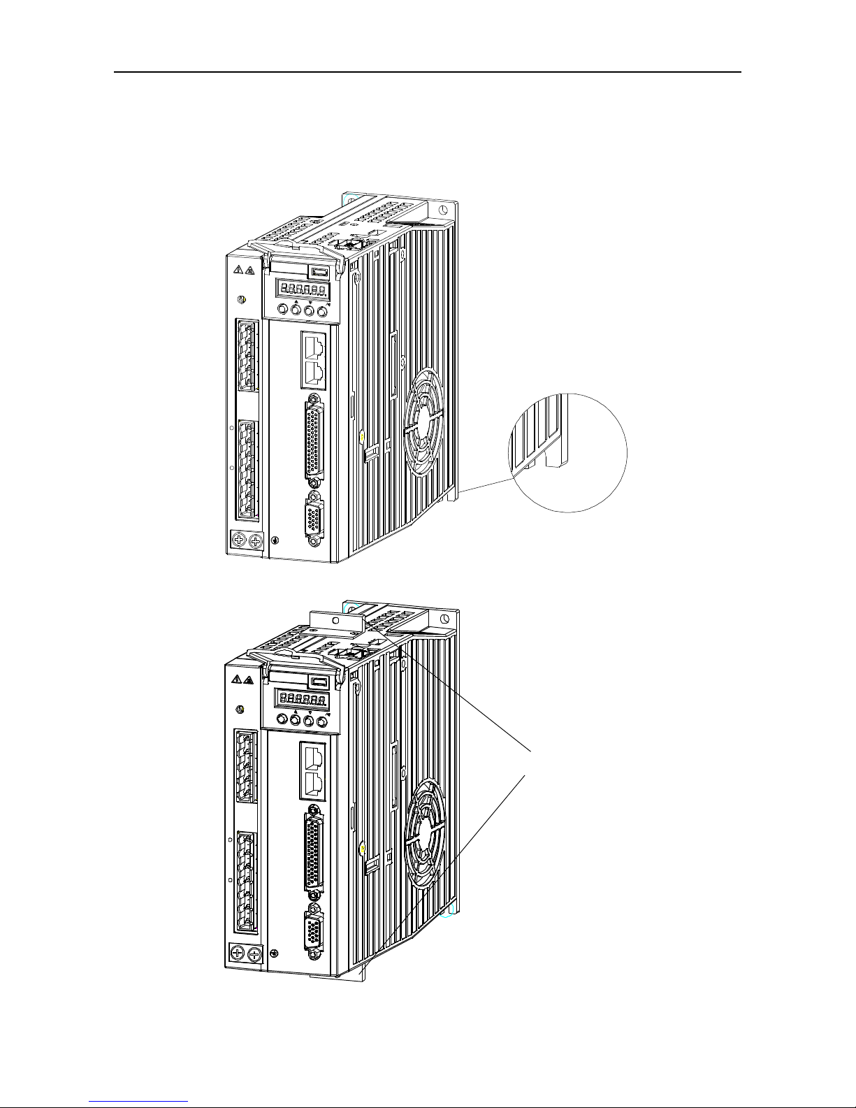
1.1.2 External appearance of the drive
Standard model
CHARGE
MOD E
SET
L3
L1C
L2C
L2
L1
C
N
4
C
N
3
C
N
1
C
N
2
B2
B3
U
V
W
CHARGE light
Power supply of main circuit
Power supply of control circuit
Motor
Grounding
Regenerative resistor
Operation panel
LED display
CN3:CAN/485 communication
CN1:I/O control
CN2:Encoder
CN5:2nd encoder and STO
S1:STO selection
CN4:USB port of up per PC
-
+
Models which carry extension cards with DP function
CHARG E
MODE
L3
L1C
L2
L1
C
N
3
C
N
1
C
N
2
B2
B3
U
V
W
SET
L2C
C
N
4
-
+
CHARGE light
Power supply of main circuit
Power supply of control circuit
Motor
Grounding
Regenerative resistor
Operation panel
LED display
CN3:CAN/485 communication
CN1:I/O control
CN2:Encoder
CN5:2nd encoder and STO
S1:STO selection
CN4:USB port of upper PC
PROFIBUS-DP interface

SV-DA200 series AC servo drive Product overview
-7-
1.1.3 Naming of the drive
SV-DA200-0R4-2-E0-XXXX
① ② ③ ④ ⑤ ⑥ ⑦
Symbol
Instruction
Naming instance
Product category
SV: Servo system product
Product series
DA200: Product series
Power class
0R1: 100W
0R2: 200W
0R4: 400W
0R7: 750W
1R0: 1.0kW
1R5: 1.5kW
2R0: 2.0kW
3R0: 3.0kW
4R4: 4.4kW
5R5: 5.5kW
7R5: 7.5kW
011: 11kW
015: 15kW
022: 22kW
037: 37kW
045: 45kW
055: 55kW
Input voltage class
2: 220VAC; 4: 400VAC
Servo type
E: Pulse type
S: Standard
C: CANopen bus type
P: PROFIBUS-DP bus type
N: EtherCAT bus type
M: MotionNet bus type
K: Customized
Encoder type
0: Photoelectric encoder
(1)
7: Rotary transformer
Lot no.
Manufacturer lot no. used for differentiating models with special
functions. Lot no. is the default one.
Remark:
(1)
: Photoelectric encoder here means 2500-PPR standard incremental type, 17-bit single
turn/multi-turn absolute and 23-bit multi-turn absolute (the same below).

SV-DA200 series AC servo drive Product overview
-8-
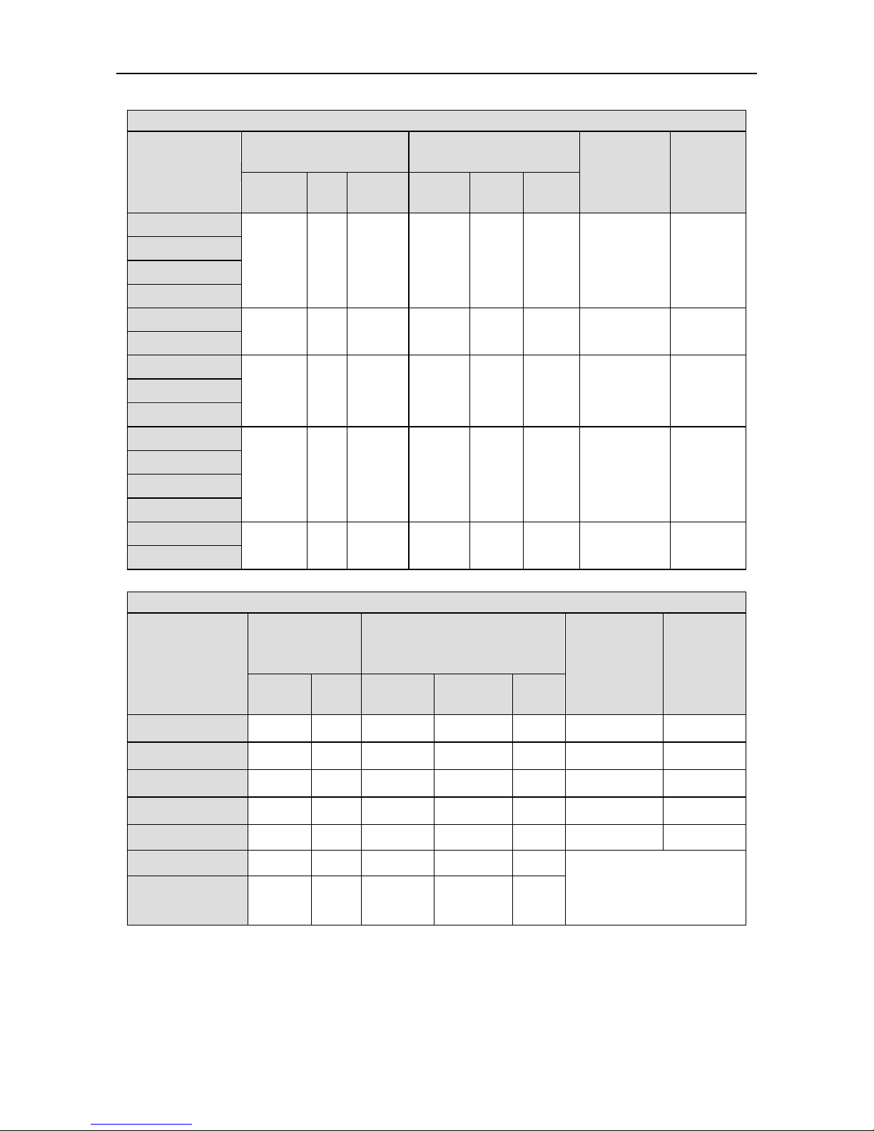
Function difference between different machine types:
Small power range: 100W–5.5kW
Drive type
Symbol
Pulse
input
16-bit
analog
input
2nd
encoder
STO
RS48
5
CAN
open
PROFI
BUS-
DP
Ether
CAT
Motion
Net
Photoelectri
c encoder
Rotary
transfor
mer
Pulse type
E0 ○ × ○ × ○ × × × × ○
×
E7 ○ × ○ × ○ × × × × ×
○
Standard
type
S0 ○ ○ ○ ○ ○ × × × × ○
×
S7 ○ ○ ○ ○ ○ × × × × ×
○
Bus type
C0 × × ○ × × ○ × × × ○
×
P0 × × ○ × × × ○ × × ○
×
N0 × × ○ × × × × ○ × ○
×
M0 × × ○ × ○ × × × ○ ○
×
Customized
K0 ○ × ○ × ○ ○ × × × ○
×
K7 ○ × ○ × ○ ○ × × × ×
○
Medium-power range: 7.5kW–55kW
Drive type
Symbol
Pulse
input
16-bit
analog
input
2nd
encoder
STO
RS48
5
CAN
open
PROF
IBUS-
DP
Ether
CAT
Motion
Net
Photoelectri
c encoder
Rotary
transfor
mer
Standard
type
S0 ○ ○ ○ ○ ○ ○ × × × ○
×
S7 ○ ○ ○ ○ ○ ○ × × × ×
○
Bus type
N0 × × ○ ○ × × × ○ × ○
×
N7 × × ○ ○ × × × ○ × ×
○
Customized
K0 ○ × ○ ○ ○ ○ × × × ○
×
K7 ○ × ○ ○ ○ ○ × × × ×
○
Note: In above table, “○” means this function is available, “×” means this function is unavailable.
1.1.4 Nameplate of the drive

SV-DA200 series AC servo drive Product overview
-9-
1.1.5 Power ratings and cabinet volumes
Model
Input
Output
Cabinet
volume
Voltage (V)
Rated current
(A)
Power
(kW)
Rated
current (A)
SV-DA200-0R1-2
Single/Three phase 220
0.9/0.4
0.1
1.3
A
SV-DA200-0R2-2
Single/Three phase 220
1.8/0.8
0.2
1.8
A
SV-DA200-0R4-2
Single/Three phase 220
3.6/1.5
0.4
2.8
A
SV-DA200-0R7-2
Single/Three phase 220
6.8/2.8
0.75
4.5
B
SV-DA200-1R0-2
Single/Three phase 220
9.1/3.7
1.0 5 B
SV-DA200-1R5-2
Three phase 220
5.6
1.5
7.6
B
SV-DA200-2R0-2
Three phase 220
7.5
2.0
10
D
SV-DA200-3R0-2
Three phase 220
11.2
3.0
13
D
SV-DA200-4R4-2
Three phase 220
16.5
4.4
16.5
D
SV-DA200-1R0-4
Three phase 400
2.1
1.0
3.5
B
SV-DA200-1R5-4
Three phase 400
3.1
1.5
4.5
B
SV-DA200-2R0-4
Three phase 400
4.1
2.0
6.5
C
SV-DA200-3R0-4
Three phase 400
6.2
3.0
8.5
C
SV-DA200-4R4-4
Three phase 400
9.1
4.4
12
D
SV-DA200-5R5-4
Three phase 400
11.3
5.5
16
D
SV-DA200-7R5-4
Three phase 400
15.5
7.5
25
F
SV-DA200-011-4
Three phase 400
22.7
11
33
F
SV-DA200-015-4
Three phase 400
31
15
50
F2
SV-DA200-022-4
Three phase 400
45.4
22
66
G
SV-DA200-037-4
Three phase 400
76.3
37
90
G
SV-DA200-045-4
Three phase 400
92.8
45
112
H
SV-DA200-055-4
Three phase 400
113.4
55
134
H

SV-DA200 series AC servo drive Product overview
-10-
1.2 Servo motor
1.2.1 Nameplate of the motor
INPUT: AC 3PH 220V 2.8A
OUTPUT(RATED): 400W 3000r/min 1.3N·m
IP65 S1 CLASS F NO.3010004(236)
MODEL: SV-ML06-0R4G-2-4A0-3000
Note: “No. 3010004” in the nameplate is the motor model code (motor code for short). Please input
this code into servo parameter P0.00 correctly (P0.00 is long parameter which can be set via keypad.
See details at chapter 5.2.1 (8), otherwise, the servo system may not operate normally and major
fault may occur to the drive and motor.
1.2.2 Naming of the servo motor
① ② ③ ④ ⑤ ⑥ ⑦ ⑧ ⑨ ⑩ ⑪
SV-ML06-0R4G-2-4A0-XXXX
Symbol
Instruction
Naming instance
Product category
SV: Servo system product
Product series
M: M series
C: C series
S: S series
Inertial class
L: Small inertia general servo motor
M: Medium inertia general servo motor
H: Large inertia general servo motor
Base no.
04: 40mm
(2)
06: 60mm
08: 80mm
11: 110mm
13: 130mm
18: 180mm
20: 200mm
26: 263mm
Rated power
0R1: 100W
0R2: 200W
0R4: 400W

SV-DA200 series AC servo drive Product overview
-11-
Symbol
Instruction
Naming instance
0R7: 750W
0R8: 800W/850W
1R0: 1.0kW
1R2: 1.2kW
1R3: 1.3kW
1R5: 1.5kW
1R8: 1.8kW
2R0: 2.0kW
3R0: 3.0kW
4R4: 4.4kW
5R5: 5.5kW
7R5: 7.5kW
011: 11kW
015: 15kW
022: 22kW
037: 37kW
045: 45kW
055: 55kW
……
Rated speed
A: 1000rpm
B: 1500rpm
E: 2000rpm
F: 2500rpm
G: 3000rpm
Voltage class
2: 220VAC
4: 380VAC
Encoder type
1: 2500-PPR standard incremental type
3: 17-bit single-turn absolute value
(1)
4: 17-bit multi-turn absolute value
7: Rotary transformer
9: 23-bit multi-turn absolute value
Shaft end
connection
A: solid with threaded hole and key (standard)
B: Solid optical axis
Optional part
0: with oil seal but no brake
1: without oil seal or brake
(3)
2: with oil seal and permanent magnet brake
3: without oil seal but with permanent magnet brake
(3)
4: with oil seal and electromagnetic brake
5: without oil seal but with electromagnetic brake
(3)
⑪
Lot no.
Manufacturer lot no.
(4)

SV-DA200 series AC servo drive Product overview
-12-
Remark:
(1)
: 17-bit absolute single turn motor belongs to a separate series and its dimension and parameters
are different. Only electromagnetic brake is used. Please pay attention to corresponding series when
selecting models;
(2)
: 40-base motor, only supports 2500-PPR and 17-bit absolute encoder;
(3)
: Non-stock up model, the ordering cycle will be delayed for 3–5 days;
(4)
: No need to fill in for the first-time model selection by customers;
In addition, the non-17 bit single-turn absolute motor with 40 or 60 base supports permanent magnet
brake only.
1.3 Cables
1.3.1 Nameplate of cables
67002-00351
5m power flexible towline cable,0.75mm cable
diameter,4PIN plastic plug,7PIN 20A plug
DAML-075-05-ABF-00
INVT INDUSTRIAL TECHNOLOGY(SHANGHAI) CO.,LTD.
上海英威腾工业技术有限公司
2
1.3.2 Naming of the power cables
DAML-075-05-ABF-00
① ② ③ ④ ⑤ ⑥ ⑦ ⑧
Symbol
Instruction
Naming instance
Product series
For internal use by manufacturer
Power cable
ML: Power cable
Cable diameter
075: 0.75mm2
100: 1.0mm2
150: 1.5mm2
250: 2.5mm
2
400: 4.0mm
2
600: 6.0mm
2

SV-DA200 series AC servo drive Product overview
-13-
Symbol
Instruction
Naming instance
10R: 10mm
2
16R: 16mm
2
25R: 25mm
2
35R: 35mm
2
50R: 50mm2
Cable length
03: 3m
05: 5m
10: 10m
……
Plug on motor end
A: 4PIN plastic plug
B: 4PIN regular aviation plug YD28
C: 4PIN metal plug
D: 7PIN regular aviation plug YD28
E: 4PIN regular aviation plug YD18
N: 4PIN regular aviation plug YD32
S: Copper tube terminal SC
Plug on drive end
B: Euro 7PIN 20A plug
W: No plug
S: Copper tube terminal SC
Cable material
0: Regular cable
A: Shielded normal cable
B: Shielded flexible towline cable
F: Flexible towline cable
Serial no.
00: Standard part
01: Serial no. for non-standard parts
……
1.3.3 Naming of power cable fittings
DAML-AB
① ② ⑤ ⑥
Symbol
Instruction
Naming instance
Product series
For internal use by manufacturer
Power cable
ML: Power cable
Plug on motor end
A: 4PIN plastic plug
B: 4PIN regular aviation plug YD28
C: 4PIN metal plug
D: 7PIN regular aviation plug YD28

SV-DA200 series AC servo drive Product overview
-14-
Symbol
Instruction
Naming instance
E: 4PIN regular aviation plug YD18
N: 4PIN regular aviation plug YD32
S: Copper tube terminal SC
Plug on drive end
B: Euro 7PIN 20A plug
W: No plug
S: Copper tube terminal SC
1.3.4 Naming of the encoder cables
DBEL-15-03-AF-0100
① ② ③ ④ ⑤ ⑥ ⑦ ⑧
Symbol
Instruction
Naming instance
Product series
For internal use by manufacturer
Encoder cable
EL: Encoder cable
Cable number
06: 6-core cable
09: 9-core cable
15: 15-core cable
Cable length
03: 3m
05: 5m
10: 10m
……
Plug on motor end
A: 15PIN DB plug
B: 15PIN regular aviation plug YD28
C: 9PIN metal plug
D: 6PIN plastic head
Cable material
0: regular cable without battery holder
D: regular cable with battery holder
F: Flexible drag chain cable without battery holder
H: Flexible drag chain cable with battery holder
Encoder type
01: 2500-PPR standard incremental type
04: 17-bit single-turn/17-bit multi-turn/23-bit multi-turn
absolute value
07: Rotary transformer
Serial no.
00: Standard part
01: Serial no. for non-standard part
……

SV-DA200 series AC servo drive Product overview
-15-
1.3.5 Naming of encoder cables fittings
DBEL-AA
① ② ⑨ ⑤
Symbol
Instruction
Naming instance
Product series
For internal use by manufacturer
Encoder cable
EL: Encoder cable
Plug on drive end
A: 15PIN DB plug
Plug on motor end
A: 15PIN DB plug
B: 15PIN regular aviation plug YD28
C: 9PIN metal plug
D: 6PIN plastic head
1.3.6 Naming of motor braking cables
BRKL-03-A
① ② ③
Symbol
Instruction
Naming instance
Product series
BRKL: motor brake cable
Cable length
03: 3m
05: 5m
10: 10m
30: 30m
Plug on motor end
A: 2PIN metal plug
B: 3PIN regular aviation plug
C: 3PIN metal plug

SV-DA200 series AC servo drive Product overview
-16-
1.4 Braking resistor specification
Drive model
Embedded braking
resistor
Min. resistance of external
braking resistors
SV-DA200-0R1-2
/
60Ω
SV-DA200-0R2-2
/
60Ω
SV-DA200-0R4-2
/
60Ω
SV-DA200-0R7-2
30Ω 60W
30Ω
SV-DA200-1R0-2
30Ω 60W
30Ω
SV-DA200-1R5-2
30Ω 60W
20Ω
SV-DA200-2R0-2
15Ω 120W
15Ω
SV-DA200-3R0-2
15Ω 120W
15Ω
SV-DA200-4R4-2
15Ω 120W
15Ω
SV-DA200-1R0-4
60Ω 60W
60Ω
SV-DA200-1R5-4
60Ω 60W
60Ω
SV-DA200-2R0-4
60Ω 60W
40Ω
SV-DA200-3R0-4
60Ω 60W
30Ω
SV-DA200-4R4-4
30Ω 120W
30Ω
SV-DA200-5R5-4
30Ω 120W
30Ω
SV-DA200-7R5-4
/
30Ω
SV-DA200-011-4
/
20Ω
SV-DA200-015-4
/
15Ω
SV-DA200-022-4
/
10Ω
SV-DA200-037-4
/
10Ω
SV-DA200-045-4
/
5Ω
SV-DA200-055-4
/
5Ω

SV-DA200 series AC servo drive Installation instruction
-17-
2 Installation instruction
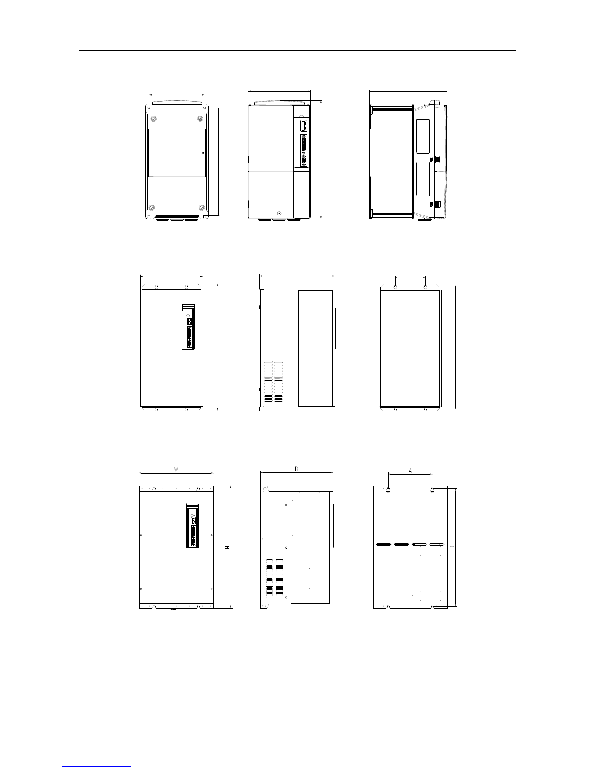
2.1 Drive dimension
2.1.1 A/B/C size and dimension diagram
2.1.2 Dimension diagram for D size
SV-DA200 series AC servo drive Installation instruction
-18-
2.1.3 Dimension diagram for F/F2 size
D
W
H
A
B
2.1.4 Dimension diagram for G size
H
W
B
A
D
2.1.5 Dimension diagram for H size

SV-DA200 series AC servo drive Installation instruction
-19-
2.1.6 Detailed dimension table
Volume
Model
External dimension
Installation dimension
Installation
hole (mm)
H(mm)
W(mm)
D(mm)
A (mm)
B1 (mm)
B2 (mm)
W1(mm)
A
SV-DA200-0R1-2
170
45
170
33
162
185
22.5
M4(Φ5)
SV-DA200-0R2-2
SV-DA200-0R4-2
B
SV-DA200-0R7-2
170
67
180
54
162
185
25
M4(Φ5)
SV-DA200-1R0-2
SV-DA200-1R5-2
D
SV-DA200-2R0-2
245
92
190
79
237
260
45
M4(Φ5)
SV-DA200-3R0-2
SV-DA200-4R4-2
B
SV-DA200-1R0-4
170
67
180
54
162
185
25
M4(Φ5)
SV-DA200-1R5-4
C
SV-DA200-2R0-4
170
84
180
71
162
185
42
M4(Φ5)
SV-DA200-3R0-4
D
SV-DA200-4R4-4
245
92
190
79
237
260
45
M4(Φ5)
SV-DA200-5R5-4
F
SV-DA200-7R5-4
342
230
208
210
311 / /
M5(Φ6)
SV-DA200-011-4
F2
SV-DA200-015-4
407
255
238
237
384 / /
M6(Φ7)
G
SV-DA200-022-4
555
270
325
130
540 / /
M6(Φ7)
SV-DA200-037-4
H
SV-DA200-045-4
554
338
328
200
535 / /
M8(Φ10)
SV-DA200-055-4
SV-DA200 series AC servo drive Installation instruction
-20-
2.2 Drive installation
2.2.1 Installation mode
1) Base installation (there is a Φ5 installation hole at the lower left corner and upper right corner of the
rear board respectively)
CHARGE
MODE
SET
L3
L1C
L2C
L2
L1
C
N
4
C
N
3
C
N
1
C
N
2
B2
B3
U
V
W
-
+
2) Bracket installation (the installation bracket is optional)
CHARGE
MODE
SET
L3
L1 C
L2 C
L2
L1
C
N
4
C
N
3
C
N
1
C
N
2
B2
B3
U
V
W
-
+
Partition bracket
SV-DA200 series AC servo drive Installation instruction
-21-
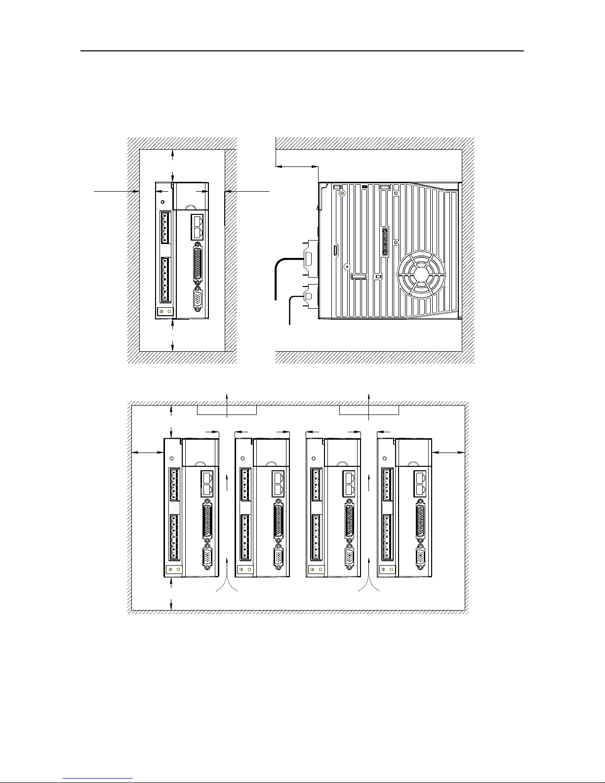
2.2.2 Installation space and direction
Please install the servo drive vertically and keep enough installation space for good ventilation. Install
fans if necessary to ensure the temperature inside the control cabinet is lower than 45.
1) Single drive installation
>100mm
>100mm
>20mm >20mm
>40mm
Up
Down
2) Multiple drives installation
>20mm
>20mm
Up
Down
>20mm
FAN FAN
>20mm
>20mm
>20mm >20mm

SV-DA200 series AC servo drive Installation instruction
-22-
2.3 Motor dimension
Note: As motor structure and dimension may vary slightly with design modification, for those who are
sensitive to the installation length of motor, please confirm the installation length with our business
staff before ordering.
2.3.1 Outline and installation dimension for 40 base (mm)
L25
Φ8h7
Φ30h7
3
4-Φ3.5
Φ46
40
40
15
3h9
9.2
M3 depth 6
A
A
A-A
Motor model
(2500-PPR/multi-turn absolute value)
L(mm)
W/o brake
Permanent magnet brake
SV-ML04-0R1G-2-A
90
124
####
Φ30h7
14
Φ8h7
L
3
25.5 40
40
3h9
9.2
M3 depth 6
2-Φ4.5
Φ46
A
A
A-A
Motor model
(17-bit single-turn encoder)
L(mm)
W/o brake
Electromagnetic brake
SV-ML04-0R1G-2-3A
90.3
123

SV-DA200 series AC servo drive Installation instruction
-23-
2.3.2 Outline and installation dimension for 60 base (mm)
L30
7.5
3
16
5h9
A-A
60.2
60.2
Φ70
Φ50h7
2
2
20.5
M4 depth 10
4-Φ5.5
A
A
Φ14h7
Motor model (2500-PPR/multi-turn absolute
value/rotary transformer)
L(mm)
W/o brake
Permanent magnet brake
SV-ML06-0R2G-2-A
116
164
SV-ML06-0R4G-2-A
141
189
SV-MH06-0R4G-2-A
147
191
4-Φ5.5
##
##
Φ50h7
Φ14h7
A
22.5
M5 depth 15
3
30
L
Φ70
60
60
16
5h9
A-A
A
2
Motor model
(17-bit single-turn encoder)
L(mm)
W/o brake
Electromagnetic brake
SV-ML06-0R2G-2-3A
114
147
SV-ML06-0R4G-2-3A
133
167

SV-DA200 series AC servo drive Installation instruction
-24-
2.3.3 Outline and installation dimension for 80 base (mm)
Φ19h
7
35 L
3
10
Φ70h7
25
M5 depth 10
80
80
Φ90
4-Φ6.3
6h9
A-A
21.5
A
A
2
Motor model (2500-PPR/multi-turn
absolute value/rotary transformer)
L(mm)
W/o brake
Permanent magnet
brake
Electromagnetic
brake
SV-ML08-0R7G-2-A
140
186
186
SV-MH08-0R7G-2-A
151
205
205
####
Φ19h7
35 L
25
Φ70h7
3
A
A
M5 depth 15
80
80
Φ90
4-Φ6.3
6h9
A-A
21.5
Φ19.5×2
Motor model
(17-bit single-turn encoder)
L(mm)
W/o brake
Electromagnetic brake
SV-ML08-0R7G-2-3A
141
173

SV-DA200 series AC servo drive Installation instruction
-25-
2.3.4 Outline and installation dimension for 110 base (mm)
110
110
Φ130
6h9A-A
Φ95h7
2.5
40
Φ19h7
12
5
55 L
M6 depth 20
21.5
4-Φ9
Φ20×2
A
A
Motor model (2500-PPR/multi-turn
absolute value/rotary transformer)
L(mm)
W/o brake
Permanent magnet
brake
Electromagnetic
brake
SV-MM11-0R8E-2-A
189
245
263
SV-MM11-1R2G-2-A
SV-MM11-1R5G-2-A
204
260
278
SV-MM11-1R2E-2-A
219
275
293
SV-MM11-1R8G-2-A

SV-DA200 series AC servo drive Installation instruction
-26-
2.3.5 Outline and installation dimension for 130 base (mm)
130
130
Φ145
Φ110h7
44
Φ22h7
12
6
55 L
M6 depth 22
6h9
A-A
24.5
4-Φ9
A
A
Φ24.4×2
Motor model (2500-PPR/multi-turn
absolute value/rotary transformer)
L(mm)
W/o brake
Permanent magnet
brake
Electromagnetic
brake
SV-MM13-1R0E--A
143
185
185
SV-MM13-1R5E--A
159
201
201
SV-MM13-2R0E--A
175
217
217
SV-MM13-3R0E--A
207
249
249
SV-MH13-0R8B--A
167
209
209
SV-MH13-1R3B--A
202
244
244
Φ110h7
Φ22h7
58
6
L
35
130
Φ145
4-Φ9
130
M6 depth 15
6h9
A-A
24.5
A
A
2
Motor model
(17-bit single-turn encoder)
L(mm)
W/o brake
Electromagnetic brake
SV-MM13-1R0E--3A
165
220
SV-MM13-1R5E--3A
185
240
SV-MM13-2R0E--3A
215
270
SV-MM13-3R0E--3A
265
320

SV-DA200 series AC servo drive Installation instruction
-27-
2.3.6 Outline and installation dimension for 180 base (mm)
L
180
180
Φ200
4-Φ13.5
A-A
38
3.2
65
3
51
Φ114.3h7
Φ38.5×2.5
10h9
M8 depth 25
A
A
Φ35h7
18
Motor model (2500-PPR/multi-turn
absolute value/rotary transformer)
L(mm)
W/o brake
Permanent magnet
brake
Electromagnetic
brake
SV-MM18-3R0B--A
232
314
304
SV-MM18-4R4B--A
262
344
334
SV-MM18-5R5B-4-A
292
382
364
SV-MM18-7R5B-4-A
346
436
418
SV-SM18-7R5B shaft extension dimension (mm):
79
3.2
64
Φ114.3h7
Φ38.5×2.5
19
Φ35h7
M8 depth 25
Motor model (2500-PPR/multi-turn
absolute value/rotary transformer)
L(mm)
W/o brake
Permanent magnet
brake
Electromagnetic
brake
SV-SM18-7R5B-4-A
375
465
455

SV-DA200 series AC servo drive Installation instruction
-28-
2.3.7 Outline and installation dimension for 200 base (mm)
82
Φ180h7
70
Φ42
M10 depth 30
300
Φ42h7
Φ215
A
A
5
L
16.5
110.5
200×200
221×221
4-Φ13.5
246
45
12h9
A-A
Motor model (2500-PPR/multi-turn
absolute value/rotary transformer)
L(mm)
W/o brake
Permanent magnet
brake
Electromagnetic
brake
SV-MH20-011B-4-A
411
547
547
SV-MH20-015B-4-A
446
582
582
2.3.8 Outline and installation dimension for 263 base (mm)
4
110 L
Φ250h7
90
52
14h9
M20 depth 35
320
263×263
292×292
Φ300
4-Φ19
371
146
Φ48h7
A
A
A-A
Motor model (2500-PPR/multi-turn absolute
value/rotary transformer)
L(mm)
W/o brake
SV-SH26-022B-4-A
537
SV-MH26-037B-4-A
537
SV-MH26-045B-4-A
577
SV-MH26-055B-4-A
620

SV-DA200 series AC servo drive Installation instruction
-29-
2.4 Motor installation
Do not pull the motor leads or output shaft during fetching and moving the motor;
Do not beat or hammer during the motor assembly to avoid damage to the encoder or shafts;
Please wipe the slushing oil on the motor shaft before using.
2.5 Technical parameters of servo motor
2.5.1 Motor specification (2500-PPR/multi-turn absolute /rotary transformer)
Motor model
(2500-PPR/multi- turn
absolute/ rotary
transformer)
Rated
power
(kW)
Rated
current
(A)
Max.
transient
current
(A)
Rated
torque
(Nm)
Max.
transient
torque
(Nm)
Rated
speed
(rpm)
Max.
speed
(rpm)
Rotation inertia
standard/ with
brake
(kg·cm²)
Voltage
(V)
Weight
standard/
with brake
(kg)
ML series small inertia
SV-ML04-0R1G-2-A
0.1
0.6
1.2
0.32
0.64
3000
5000
0.051/0.055
220
0.47/0.67
SV-ML06-0R2G-2-A
0.2
1.2
3.6
0.64
1.91
0.175/0.22
1.16/1.66
SV-ML06-0R4G-2-A
0.4
2.8
8.4
1.27
3.9
0.29/0.33
1.6/2.1
SV-ML08-0R7G-2-A
0.75
4.5
13.5
2.39
7.2
1.28/1.51
3.0/3.5
MM/SM series medium inertia
SV-MM11-0R8E-2-A
0.8
3.5
10.5 4 12
2000
3000
5.4/6.7
220
6/7.7
SV-MM11-1R2E-2-A
1.2
4.5
13.5 6 18
7.6/8.9
7.9/9.6
SV-MM11-1R2G-2-A
1.2 5 15 4 12
3000
4000
5.4/6.7
6/7.7
SV-MM11-1R5G-2-A
1.5 6 18 5 15
6.3/7.6
6.8/8.5
SV-MM11-1R8G-2-A
1.8 6 18 6 18
7.6/8.9
7.9/9.6
SV-MM13-1R0E-2-A
1
4.8
14.4
4.78
14.3
2000
3000
6.4/8.3
5.8/7.5
SV-MM13-1R5E-2-A
1.5
7.6
22.8
7.16
21.4
9.3/11.2
7.1/8.8
SV-MM13-2R0E-2-A
2
9.5
28.5
9.55
28.6
12.2/14.1
8.4/10.1
SV-MM13-3R0E-2-A
3
13.6
40.8
14.3
42
18/19.9
10.8/12.5
SV-MM13-1R0E-4-A
1
2.8
8.4
4.78
14.3
6.4/8.3
380
5.8/7.5
SV-MM13-1R5E-4-A
1.5
4.5
13.5
7.16
21.4
9.3/11.2
7.1/8.8
SV-MM13-2R0E-4-A
2
5.5
16.5
9.55
28.6
12.2/14.1
8.4/10.1
SV-MM13-3R0E-4-A
3
7.8
23.4
14.3
42
18/19.9
10.8/12.5
SV-MM18-3R0B-2-A
3
12
29.7
19
47
1500
2000
70/74
220
20.5/25
SV-MM18-4R4B-2-A
4.4
16
39.7
27
67
97/101
25.5/30
SV-MM18-3R0B-4-A
3
7.5
18.7
19
47
70/74
380
20.5/25
SV-MM18-4R4B-4-A
4.4
10
25
27
67
97/101
25.5/30
SV-MM18-5R5B-4-A
5.5
12
24
35
70
86/127
30.5/35.7
SV-MM18-7R5B-4-A
7.5
20
40
48
96
168/179
40/46.5
SV-SM18-7R5B-4-A
7.5
24
62
48
120
1500
3000
190/201
380
46/52.5

SV-DA200 series AC servo drive Installation instruction
-30-
Motor model
(2500-PPR/multi- turn
absolute/ rotary
transformer)
Rated
power
(kW)
Rated
current
(A)
Max.
transient
current
(A)
Rated
torque
(Nm)
Max.
transient
torque
(Nm)
Rated
speed
(rpm)
Max.
speed
(rpm)
Rotation inertia
standard/ with
brake
(kg·cm²)
Voltage
(V)
Weight
standard/
with brake
(kg)
MH/SH series large inertia
SV-MH06-0R4G-2-A
0.4
2.8
8.4
1.27
3.81
3000
5000
0.67/0.77
220
2.0/2.2
SV-MH08-0R7G-2-A
0.75
4.5
13.5
2.39
7.2
2.5/2.73
3.3/3.8
SV-MH13-0R8B-2-A
0.85
5.5
16.5
5.41
16.2
1500
2000
13.4/15.4
6.6/8.3
SV-MH13-1R3B-2-A
1.3
8.2
24.6
8.34
25
23.4/25.4
9.3/11
SV-MH13-0R8B-4-A
0.85
3.2
9.6
5.41
16.2
13.4/15.4
380
6.6/8.3
SV-MH13-1R3B-4-A
1.3
4.8
14.4
8.34
25
23.4/25.4
9.3/11
SV-MH20-011B-4-A
11
22.7
69
70
175
98.3/106.3
49/66
SV-MH20-015B-4-A
15
42.5
107
95.5
240
119/127
56/73
SV-SH26-022B-4-A
22
61
153
140
350
390/412
103/133
SV-MH26-037B-4-A
37
74.6
187
187
468
1800
2300
380
115
SV-MH26-045B-4-A
45
100
250
210
525
2000
2500
447
121
SV-MH26-055B-4-A
55
114
285
290
725
1800
2300
728
150
Insulation class
Class F (155)
Protection class
IP65
Application
environment
Temperature: -20–+40 (non-frozen); RH: below 90%RH (No condensation)

SV-DA200 series AC servo drive Installation instruction
-31-
2.5.2 Motor specification (17-bit single-turn absolute value)
Motor model
(17-bit single-turn absolute
value)
Rated
power
(kW)
Rated
current
(A)
Max.
transien
t current
(A)
Rated
torque
(Nm)
Max.
transient
torque
(Nm)
Rated
speed
(rpm)
Max.
speed
(rpm)
Rotational
inertia
standard/with
brake
(kg·cm²)
Voltage
(V)
Weight
standard/
with brake
(kg)
ML series small inertia
SV-ML04-0R1G-2-3A
0.1
1.1
3.3
0.32
0.96
3000
5000
0.036/0.037
220
0.47/0.67
SV-ML06-0R2G-2-3A
0.2
1.2
3.6
0.64
1.92
3000
5000
0.176/0.179
1.01/1.4
SV-ML06-0R4G-2-3A
0.4
2.3
6.9
1.27
3.81
0.3/0.302
1.37/1.78
SV-ML08-0R7G-2-3A
0.75
4.3
12.9
2.5
7.5
1.015/1.018
2.5/3.4
MM series medium inertia
SV-MM13-1R0E-2-3A
1
4.72
14.2
4.77
14.3
2000
2500
8.71/8.72
220
6.41/7.94
SV-MM13-1R5E-2-3A
1.5
6.87
20.6
7.16
21.5
12.08/12.1
7.9/9.4
SV-MM13-2R0E-2-3A
2
9.18
27.5
9.55
28.6
17.14/17.16
10.12/
11.67
SV-MM13-3R0E-2-3A
3
12.95
38.85
14.3
42.9
25.58/25.59
13.8/15.4
SV-MM13-1R0E-4-3A
1
2.5
7.5
4.77
14.3
8.71/8.72
380
6.41/7.94
SV-MM13-1R5E-4-3A
1.5
4.1
12.3
7.16
21.5
12.08/12.1
7.9/9.4
SV-MM13-2R0E-4-3A
2
6.5
19.5
9.55
28.6
17.14/17.16
10.12/
11.67
SV-MM13-3R0E-4-3A
3
9.6
28.8
14.3
42.9
25.58/25.59
13.8/15.4
Insulation class
Class F(155)
Protection class
IP65
Application
environment
Tempetaure: -20 to +40 (non-frozen); RH: below 90%RH (no condensation)
SV-DA200 series AC servo drive Wiring instruction
-32-
3 Wiring instruction
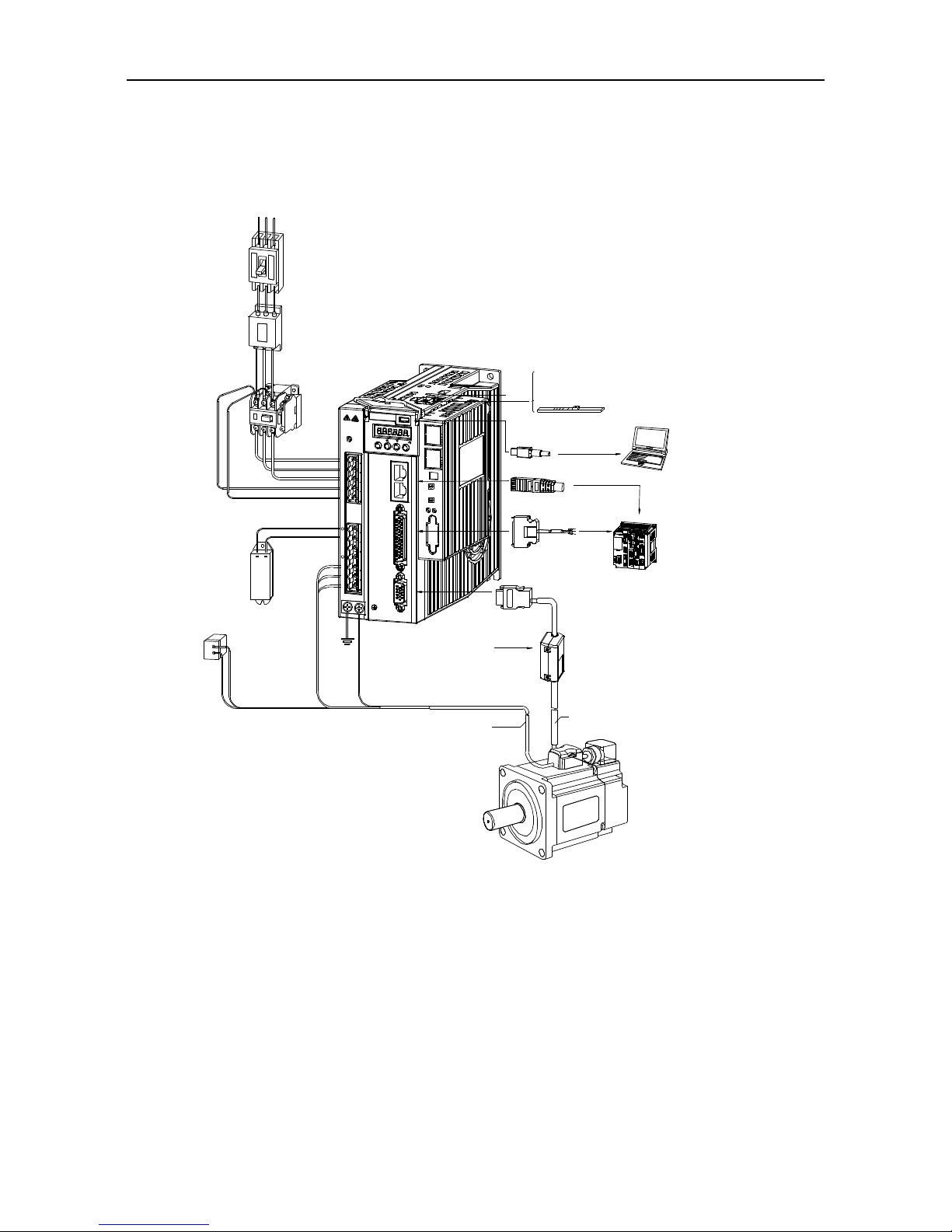
3.1 System wiring
L1 L 2 L3
Electromagnetic
contactor
Turn on/off servo
power.
Please install surge
suppressor duing
usage.
Breaker
Power
ST O
sw itch
PC connection cable
PC
C
N
CHARGE
SET
MODE
4
L2
L1
L1C
L3
3
N
C
CAN/485 communication
Grating ruler or the second encoder
Signal cable (I/O)
Upper device
L2C
+
N
C
-
B3
U
V
B2
1
C
N
2
W
Encoder signal
Safety input signal is valid
and corre ct wirin g is needed
when S TO safety function is
not use d, namely STO is not
set to O N .
Safety input term in al signal is
invalid an d wiring is not needed
when S TO safety prote ction
fun ction is used, nam ely when
STO switch is set to O N
Encoder connection cable
Main circuit cable of motor
Servo motor
Battery unit
(when absolute encoder is used)
Brake power
(
DC 24V, provided by the user
)
Regenerative
brake resistor
Noise filter
Prevent the noise outside
the power cable
Used to cut off the circuit
when p ower cable flows
throu gh o vercurrent
Check to ensure the input power supply indicated on the nameplate is the same as that of the
grid before connecting the input power supply of the drive.
The electromagnetic contactor is used to switch on/off the power supply of the main circuit of
the servo drive. Do not use it to start/stop the servo drive.
In the above figure, the external regenerative brake resistor is connected, and the short
connection wire between B2 and B3 should be removed, refer to chapter 3.2 for details. The
external regenerative brake resistor must be installed on flame-resistance material which has good
cooling effect eg metal.

SV-DA200 series AC servo drive Wiring instruction
-33-
3.1.1 Requirements on input power cable
The dimension of input power cable shall comply with local regulations.
The input power cable must be able to withstand corresponding load current.
The max rated temperature margin of input power cable should not be lower than 70 under
continuous operation.
See IEC/EN 61800-3:2004 for EMC requirements.
It is recommended to use shielded four-core cable for input cable
Conductor
Sleeve
Insulation
PE
Shielded
layer
Four-core cable with shielded layer
In order to protect the conductors, the cross section of shielded cable must the same with that of the
phase conductor when the shielded cable and phase conductor use the same material, which will
help reduce grounding resistor to improve impedance continuity.
In order to suppress the emission and transmission of RF, the conductivity of shielded cable must be
at least 1/10 of phase conductor conductivity. The coverage rate of shielded layer must be above 85%
at least.
3.1.2 Requirements on control cable
All the analog control cables and the cables used for frequency input must use shielded cable. The
analog signal cable uses shielded twisted pair (figure a). Each signal adopts a pair of independent
shielded twisted pair. Different analog signal cannot use the same ground wire.
Multiple double-shielded twisted pairs Multiple single-shielded twisted pairs
For low voltage digital signal, it is recommended to use double-layer shielded cables, single-layer
shielded pairs or shieldless pairs (figure b), however, for pulse input signal, only shielded cable can
be used.
Communication cable must use shielded twisted pairs.
SV-DA200 series AC servo drive Wiring instruction
-34-
3.1.3 Cable diameter of main circuit
Small power range (100W–5.5kW) main circuit cable diameter table
Drive model
Recommended cable
diameter (mm2)
Connectable cable
diameter (mm2)
Terminal
screw
specification
Tightening
torque
(Nm)
L1\L2\L3
UVW
PE
L1C\L2C
L1\L2\L3
UVW
(+), B2,
B3, (-)
PE
SV-DA200-0R1-2
0.75
0.75
0.75
0.75–4
0.75–4
0.75–4
M2.5
0.3–0.6
SV-DA200-0R2-2
SV-DA200-0R4-2
SV-DA200-0R7-2
SV-DA200-1R0-2
1.5
1.5
0.75
1.5–4
1.5–4
1.5–4
M2.5
0.3–0.6
SV-DA200-1R5-2
SV-DA200-2R0-2
2.5
2.5
0.75
2.5–4
2.5–4
2.5–4
M4
1.2–1.5
SV-DA200-3R0-2
SV-DA200-4R4-2
SV-DA200-1R0-4
1.5
1.5
0.75
1.5–4
1.5–4
1.5–4
M2.5
0.3–0.6
SV-DA200-1R5-4
SV-DA200-2R0-4
SV-DA200-3R0-4
SV-DA200-4R4-4
2.5
2.5
0.75
2.5–6
2.5–6
2.5–6
M4
1.2–1.5
SV-DA200-5R5-4
Medium power range (7.5kW–55kW) main circuit cable diameter table
Drive model
Recommended
cable diameter
(mm2)
Connectable cable diameter
(mm2)
Terminal
screw
specification
Tightening
torque
(Nm)
RST
UVW
PE
RST
UVW
(+), PB, (-)
PE
SV-DA200-7R5-4
6 6 6–16
6–10
6–10
M5
2–2.5
SV-DA200-011-4
10
10
10–16
10–16
6–16
M5
2–2.5
SV-DA200-015-4
16
16
16–25
16–25
10–16
M6
4–6
SV-DA200-022-4
25
16
25–50
25–50
16–25
M8
9–11
SV-DA200-037-4
35
16
25–50
25–50
16–25
M8
9–11
SV-DA200-045-4
50
25
35–95
25–95
25–35
The terminal adopts nuts,
users are suggested to use
spanners or sleeves
SV-DA200-055-4
70
35
50–95
50–95
25–35

SV-DA200 series AC servo drive Wiring instruction
-35-
3.1.4 EMI filter
Drive model
EMI filter model
SV-DA200-0R1-2
FLT-P04006L-B
SV-DA200-0R2-2
SV-DA200-0R4-2
SV-DA200-0R7-2
SV-DA200-1R0-4
SV-DA200-1R5-4
SV-DA200-1R0-2
FLT-P04016L-B
SV-DA200-1R5-2
SV-DA200-2R0-4
SV-DA200-3R0-4
SV-DA200-2R0-2
SV-DA200-3R0-2
FLT-P04032L-B
SV-DA200-4R4-4
SV-DA200-4R4-4
SV-DA200-5R5-4
SV-DA200-7R5-4
FLT-P04045L-B
SV-DA200-011-4
SV-DA200-015-4
FLT-P04065L-B
SV-DA200-022-4
FLT-P04100L-B
SV-DA200-037-4
FLT-P04150L-B
SV-DA200-045-4
FLT-P04200L-B
SV-DA200-055-4
FLT-P04250L-B
Note: The EMI filter models in the table are the models of our company and they are used for power
input terminal.

SV-DA200 series AC servo drive Wiring instruction
-36-
3.2 Terminal wiring of the main circuit
3.2.1 Wiring diagram of single phase 220V (small power range: 100W–5.5kW)
· Do not disconnect the short
connection cable between B2 and
B3, unless external regenerative
brake resistor is used;
· When external regenerative brake
resistor is used, disconnect the short
connection cable between B2 and
B3 and make connection based on
the dotted lines in the diagram.
· Connect output U, V and W to the
drive according to the motor cable
phase sequence of servo motor,
wrong phase sequence will cause
drive fault
· Be sure to ground the servo drive to
avoid accident of electrical shock.
· The electromagnetic brake uses 24V
power supply which should be
provided by the user. Moreover, it
must be isolated from the DC12-24V
power supply which is used by the
control signal.
· Pay attention to the connection of
the freewheeling diode. Reversed
polarity may damage the drive.
· The user is required to make this
emergency stop protection circuit.
· Add surge absorbing devices on
both ends of the electromagnetic
contactor winding.
· The power input voltage range:
AC 220V(-15%)~240V(+10%)
· Connect main circuit to terminal L1
and terminal L3.
· Note: Please use 3-phase input
power for the drive of 1.5kW and
above.
Yellow/Green
Surge absorber
Fuse
Breaker
MC
MC
ALM
CN1
Emergency
stop button
RY
EMI
filter
DC 12~24V
(±10%)
DC 24V
(±10%)
OFF
ALM
ON
+
-
+
-
Motor
L1
L2
L3
L1C
L2C
B3
+
B2
U
V
W
-
COM-
ALM

SV-DA200 series AC servo drive Wiring instruction
-37-
3.2.2 Wiring diagram of three phase 220V/400V (small power range: 100W–5.5kW)
· Input voltage range of 220V system:
AC 220V(-15%)~240V(+10%)
· Input voltage range of 400V system:
AC 380V(-15%)~440V(+10%)
· Do not disconnect the short circuit
wire between B2 and B3 unless an
external regenerative braking
resistor is used.
· When an external regenerative
braking resistor is used, disconnect
the short circuit wire between B2 and
B3, and connect it according to the
dotted line in the figure.
· Connect the output U, V and W of
the drive to the servo motor correctly
according to the phase sequence of
the motor cable of the servo motor.
Wrong phase sequence will cause
drive fault.
· Be sure to ground the servo drive to
avoid accident of electrical shock.
· The electromagnetic brake uses 24V
power supply which should be
provided by the user. Moreover, it
must be isolated with the DC12-24V
power supply which is used by the
control signal.
· Pay attention to the connection of the
freewheeling diode. Reversed
polarity may damage the drive.
· The user is required to make this
emergency stop protection circuit.
· Add surge absorbing devices on both
ends of the electromagnetic
contactor winding.
Surge absorber
Fuse
Breaker MC
MC
ALM
CN1
Emergency
stop button
RY
EMI
filter
DC 12~24V
(±10%)
DC 24V
(±10%)
OFF
ALM
ON
+
-
+
-
Motor
L1
L2
L3
L1C
L2C
B3
+
B2
U
V
W
-
COM-
ALM
Green/Yellow

SV-DA200 series AC servo drive Wiring instruction
-38-
3.2.3 Wiring diagram of three phase 400V (medium power range: 7.5kW–55kW)
· Input voltage range of 400V system:
AC 380V(-15%)~440V(+10%)
· It is necessary to connect external
regenerative brake resistor between
terminal (+) and PB
· Be sure to ground the servo drive to
avoid accident of electrical shock.
· The electromagnetic brake uses 24V
power supply which should be
provided by the user. Moreover, it
must be isolated from the DC12-24V
power supply which is used by the
control signal.
· Pay attention to the connection of the
freewheeling diode. Reversed
polarity may damage the drive.
· The user is required to make this
emergency stop protection circuit.
· Add surge absorbing devices on both
ends of the electromagnetic
contactor winding.
Fuse
Breaker
MC
MC
RY
DC 24V
(±10%)
OFF
ALM
ON
+
-
R
S
T
(+)
PB
(-)
U
V
W
· Connect output U, V and W to the
drive according to the motor cable
phase sequence of servo motor,
wrong phase sequence will cause
drive fault
Motor
ALM
CN1
+
COM-
ALM
Green/Yellow
Emergency
stop button
Surge absorber
EMI
filter
DC 12~24V
(±10%)

SV-DA200 series AC servo drive Wiring instruction
-39-
3.3 Wiring of motor power cables
3.3.1 2500-PPR 40/60/80-base 100W–750W motor power cable
X2
X1
1
2
3
4
6
7
5
A
12
34
A direction view
PE
W
V
U
Wiring relation
Definition
X1
X2
Core wire color
W
X1.7
X2.3
Brown
V
X1.6
X2.1
Red
U
X1.5
X2.2
Blue
PE
Ground terminal
X2.4
Yellow/green
/
X1.4 / / / X1.3
Short connect to X1.2
/
X1.2
Short connect to X1.3
/
X1.1 / /
3.3.2 17-bit or 23-bit 40/60/80-base 100W–750W motor power cable
X2
X1
1
2
3
4
6
7
5
A direction view
PE
W
V
U
A
1234
Wiring relation
Definition
X1
X2
Core wire color
W
X1.7
X2.1
Brown
V
X1.6
X2.3
Red
U
X1.5
X2.4
Blue
PE
Ground terminal
X2.2
Yellow/green
/
X1.4 / / / X1.3
Short connect to X1.2
/
X1.2
Short connect to X1.3
/
X1.1 / /
3.3.3 110/130-base 800W–1.5kW (220V) and 1kW–3kW (380V) motor power cable (except 130
base 17-bit single-turn with brake)
1
2
4
3
X2
X1
1
2
3
4
6
7
5
A
A direction view
PE
W
V
U

SV-DA200 series AC servo drive Wiring instruction
-40-
Wiring relation
Definition
X1
X2
Core wire color
W
X1.7
X2.4
Brown
V
X1.6
X2.3
Red
U
X1.5
X2.2
Blue
PE
Ground terminal
X2.1
Yellow/green
/
X1.4 / /
/
X1.3
Short connect to X1.2
/
X1.2
Short connect to X1.3
/
X1.1 / /
3.3.4 130/180-base 2kW–4.4kW (220V) and 4.4kW–7.5kW (380V) motor power cable (except for
130 base 17-bit single-turn with brake)
1
2
4
3
X2
X1
A
A direction view
PE
Brown
red
Blue
W
V
U
Wiring relation
Definition
X2
Core wire color
W
X2.4
Brown
V
X2.3
Red
U
X2.2
Blue
PE
X2.1
Yellow/green
3.3.5 200/260-base 11kW–55kW (380V) motor power cable
U
V
W
PE
PE
Ye llow
Green
Red
Ye llow
Green
Red
U
V
W
3.3.6 130-base 17-bit single-turn motor power cable with brake
X2
X1
1
2
3
4
6
7
5
A
A direction view
PE
Brake1
Brake2
W
V
U
1
2
3
4
6
7
5
Wiring relation
Definition
X1
X2
Core wire color
W
X1.7
X2.4
Brown
V
X1.6
X2.3
Red U X1.5
X2.2
Blue
PE
Ground terminal
X2.1
Yellow/green
/
X1.4 / /
/
X1.3
Short connect to X1.2
/
X1.2
Short connect to X1.3
/
X1.1 / /
Brake 1
Y shape terminal
X2.6
Red
Brake 2
Y shape terminal
X2.7
Black

SV-DA200 series AC servo drive Wiring instruction
-41-
3.4 Control I/O-CN1 terminal layout
CN1 plug pin layout
CN1 plug signal layout
44 43 42 41 40 39 38 37 36 35 34 33 32 31
30 29 28 27 26 25 24 23 22 21 20 19 18 17
15 14 13 12 11 10 9 8 7 6 5 4 3 2161
OA+ OA- OB- OB+ 24V DI4 OCP DI2 OCA GND DI5 SIGN- SIGN+ OCS
OCB DO4 OZ+ OZ- OCZ AO2 PULS-PULS+ DI10 AO1 AD2 GND DI9 DI6
DO2 DO1 DO6 COM- DO3 DI3 DO5 GND AD3 GND GND DI8 DI7 COM+
DI1
AD1
Remark: This is the interface definition for standard model; refer to chapter 4 for terminal
function and application. See corresponding operation guide for EtherCAT bus type.
3.5 Wiring of encoder-CN2 terminals
3.5.1 CN2 terminals
5 4 3 2 1
10 9 8 7 6
15 14 13 12 11
CN2 terminal function
Pin
Name
Function
Remark
1
V+/ SD+
Parallel encoder V+/Serial encoder data+
Different
encoders use
different
cables
2
W+
Signal of parallel encoder W+
3
A+
Signal of parallel encoder A+
4
A-
Signal of parallel encoder A-
5
5V
Encoder power supply
6
U+
Signal of parallel encoder U+
7
V- /SD-
Parallel encoder V-/Serial encoder data-
8
W-
Signal of parallel encoder W-
9
B-
Signal of parallel encoder B-
10
B+
Signal of parallel encoder B+
11
U-
Signal of parallel encoder U-
12
GND
Power ground
13
Z-
Signal of parallel encoder Z-
14
Z+
Signal of parallel encoder Z+
15
-
Unused

SV-DA200 series AC servo drive Wiring instruction
-42-
3.5.2 2500-PPR 40, 60, 80-base encoder cable
1
11
15
5
X2
B
B d irection v iew
1
11
15
5
6
10
X1
A
6
10
A d irection v iew
Wiring relation
Signal
X1
X2
Core wire structure
V+
X1.1
X2.1
Twisted pair
V-
X1.7
X2.7
W+
X1.2
X2.2
Twisted pair
W-
X1.8
X2.8
A+
X1.3
X2.3
Twisted pair
A-
X1.4
X2.4
U+
X1.6
X2.6
Twisted pair
U-
X1.11
X2.11
B-
X1.9
X2.9
Twisted pair
B+
X1.10
X2.10
Z-
X1.13
X2.13
Twisted pair
Z+
X1.14
X2.14
5V
X1.5
X2.5
Twisted pair
GND
X1.12
X2.12
PE
Steel casing
Steel casing
3.5.3 2500-PPR 110, 130, 180, 200 base encoder cable
12
5 3
610
1113
15 14
1
11
15
5
6
10
X1
X2
A
B
B d irection v iew
A d irection v iew
Wiring relation
Signal
X1
X2
Core wire structure
V+
X1.1
X2.11
Twisted pair
V-
X1.7
X2.14
W+
X1.2
X2.12
Twisted pair
W-
X1.8
X2.15
A+
X1.3
X2.7
Twisted pair
A-
X1.4
X2.4
U+
X1.6
X2.10
Twisted pair
U-
X1.11
X2.13
B-
X1.9
X2.8
Twisted pair
B+
X1.10
X2.5
Z-
X1.13
X2.9
Twisted pair
Z+
X1.14
X2.6
5V
X1.5
X2.2
Twisted pair
GND
X1.12
X2.3
PE
Steel casing
Steel casing

SV-DA200 series AC servo drive Wiring instruction
-43-
3.5.4 17-bit and 23-bit 40, 60, 80 base encoder cable
B
7
6
5
4
3
2
1
8
9
X2
B direc tion view
A d irection v iew
1
11
15
5
6
10
X1
A
Wiring relation
Signal
X1
X2
Core wire structure
SD+
X1.1
X2.1
Twisted pair
SD-
X1.7
X2.2
5V
X1.5
X2.3
Twisted pair
GND
X1.12
X2.4
VB-5V / X2.5
Twisted pair
VB-GND / X2.6
PE
Steel casing
Steel casing
Weaving
3.5.5 17-bit and 23-bit 110, 130, 180, 200 base encoder cable
12
35
610
11
13
1415
X2
B
B d irection view
A direc tion view
1
11
15
5
6
10
X1
A
Wiring relation
Signal
X1
X2
Core wire structure
SD+
X1.1
X2.2
Twisted pair
SD-
X1.7
X2.3
5V
X1.5
X2.4
Twisted pair
GND
X1.12
X2.5
VB-5V / X2.6
Twisted pair
VB-GND / X2.7
PE
Steel casing
X2.1
Weaving
3.5.6 Rotary transformer encoder cable
12
3
5
610
11
13
1415
X2
B
A direc tion view
B d irection view
1
11
15
5
6
10
X1
A
Wiring relation
Signal
X1
X2
Core wire structure
SIN+
X1.1
X2.6
Twisted pair
SIN-
X1.7
X2.7
COS+
X1.2
X2.5
Twisted pair
COS-
X1.8
X2.4
R+
X1.5
X2.3
Twisted pair
R-
X1.12
X2.2
PE
Steel casing
X2.1
Weaving

SV-DA200 series AC servo drive Wiring instruction
-44-
3.6 Wiring of 485/CAN-CN3 terminals
Pin8
Pin1
CN3 terminal function
Pin
Name
Function
Remark
1
GND_CAN
CAN chip power GND
485 and CAN use the
same interface and each
signal has two pins for
multiple networking.
2
GND_485
485 chip power GND
4
RS485+
RS485 data +
5
RS485-
RS485 data -
7
CAN_L
CAN data -
8
CAN_H
CAN data +
3, 6 - Unused
Note: EtherCAT bus-type drive, this port is standard network cable port definition, namely pin 1, 2, 3
and 6 correspond to Tx+, Tx-, Rx+ and Rx- respectively.
3.7 Wiring of USB-CN4 terminals
Pin5
Pin1
CN4 USB port function
Pin
Name
Functions
Remark
2
D-
Data -
The standard cable for USB micro to
USB-A conversion is available.
3
D+
Data +
5
GND
Signal ground
1, 4 - Unused
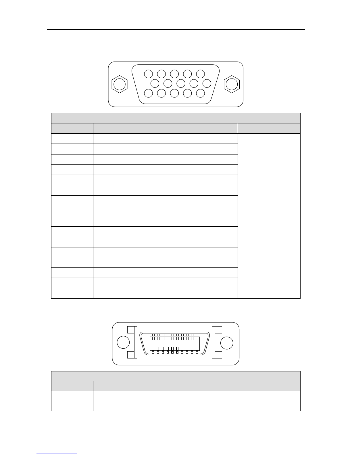
SV-DA200 series AC servo drive Wiring instruction
-45-
3.8 2nd encoder and STO-CN5 terminal wiring
3.8.1 Terminal interface and definition of small power range (100W–5.5kW)
5 4 3 2 1
10 9 8 7 6
15 14 13 12 11
Small power range CN5 port function
Pin
Name
Function
Remark
1
HWBB1+
Safety input 1+
Connect to linear
encoder or 2nd
encoder
2
HWBB2+
Safety input 2+
3
EXA+
Linear encoder (2nd encoder) A+
4
EXA-
Linear encoder (2nd encoder) A-
5
EX5V
Power supply +5V
6
EDM+
Safety monitoring output +
7
HWBB1-
Safety input 1-
8
HWBB2-
Safety input 2-
9
EXB-
Linear encoder (2nd encoder) B-
10
EXB+
Linear encoder (2nd encoder) B+
11
EDM-
Safety monitoring output -
12
EX0V
Power ground, be connected with
internal GND
13
EXZ-
Linear encoder (2nd encoder) Z-
14
EXZ+
Linear encoder (2nd encoder) Z+
15
-
Unused
3.8.2 Terminal interface and definition of medium power range (7.5kW–55kW)
110
20 11
CN5 terminal function table
Pin no.
Name
Function
Remark
1
EXA+
Linear encoder (2nd encoder) A+
Connect to
linear encoder
2
EXA-
Linear encoder (2nd encoder) A-

SV-DA200 series AC servo drive Wiring instruction
-46-
CN5 terminal function table
Pin no.
Name
Function
Remark
3
EXB+
Linear encoder (2nd encoder) B+
or 2nd encoder
4
EXB-
Linear encoder (2nd encoder) B-
5
EXZ+
Linear encoder (2nd encoder) Z+
6
EXZ-
Linear encoder (2nd encoder) Z-
7, 9
EX5V
Power +5V
8, 10
EX0V
Power GND, connected to internal GND
11
HWBB1+
Safety input 1+
12
HWBB1-
Safety input 1-
13
EDM+
Safety monitoring input+
14
EDM-
Safety monitoring input-
15
HWBB2+
Safety input 2+
16
HWBB2-
Safety input 2-
17
OC_EXZ
Z phase open collector input
18
OC_EXB
B phase open collector input
19
OC_EXA
A phase open collector input
20
-
Unused
3.9 Wiring of PROFIBUS-DP terminals
DP plug pin layout
DP plug signal layout
GND_BUS RTS B_Line - -
- A_Line - +5V_BUS
5 4 3 2 1
9 8 7 6
DP port function
Pin
Name
Function
Remark
3
B-Line
Data +
DP standard terminals and
pin connection; this
terminal is on extension
card
4
RTS
Request sending
5
GND_BUS
Isolation ground
6
+5V_BUS
5V isolation power
8
A-Line
Data -
1, 2, 7, 9 - Unused
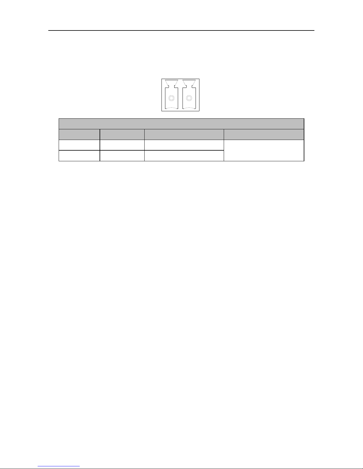
SV-DA200 series AC servo drive Wiring instruction
-47-
3.10 Wiring of motor temperature resistor-CN7 terminal in medium
power range (7.5kW–55kW)
1
2
Function of CN7 port
Pin no.
Name
Function
Remark
1
T1
KTY84-1
Support KTY84 only
2
T2
KTY84-2
Note: The motor temperature sampling function is turned off by default. Set P4.45 [Temperature
protection threshold of medium-power motor] to a non-zero value. The value of current temperature
can be read via R0.60 [Temperature of medium-power motor].

SV-DA200 series AC servo drive Control mode applications
-48-
4 Control mode applications
4.1 Standard wiring of the position mode
Frequency
divider
36 OCA
Output voltage range:
DC -10V~+10V;
Max output current:
3mA.
Position control mode
Analog torque limit of positive direction
(0V~+10V)
Analog torque limit of negative direction
(-10V~0V)
External
controller
Note: User-supplied power
DC12~24V
- +
EMG 39
SON 16
ZRS 37
POT 3
NOT 4
CLA 10
SC1 34
SC2 17
RPC 18
PLL 22
Command pulse
disabled
Retention pulse
clearing
Molecule 2 of electric
gear ratio
Molecule 1 of electric
gear ratio
Alarm clearing
Negative direction
drive disabled
Emergency stop
Servo enabling
Zero speed clamp
Positive direction
drive disabled
COM- 12
COM+ 2
24V 40
Internal DC24V power
Note: Capacity 100mA
12 COM-
15 ALM
14 RDY
29 ZSO
11 PLR
13 LM
9 BRK
44 OA+
43 OA-
41 OB+
42 OB-
FG
26 OCZ
30 OCB
AD2 20
GND 19
AD3 7
GND 8
FG
21 AO1
5 GND
25 AO2
6 GND
FG
Torque monitoring output
Speed monitoring output
AM26LS32
or equivalent chip
Note: User-supplied power
VccDC30V
- +
Fault
Servo ready
Speed zero
Positioning finished
Torque limiting
Brake release
Differential command
pulse input (max 4Mpps)
PULS+ 23
PULS- 24
OCP 38
2kΩ
SIGN+ 32
SIGN- 33
OCS 31
2kΩ
FG
PULS+ 23
PULS- 24
SIGN- 33FGSIGN+ 32
24V power, built-in current limit resistor
12~24V power, connect to external current
limit resistor
V
DC
12~24V
OCP 38
PULS- 24
SIGN- 33FGOCS 31
V
DC
24V
R R
V
DC
-1.5
R+68
10mA
Note: Max input of open collector is 200kpps
12V 1k,1/4W
24V 2k,1/3W
V
DC
R parameter
Ref
Max load capacity
of each output
terminal is
DC30V, 50mA
V
cc
DC30V;
OCA/B/Z
output current
50mA
28 OZ+
27 OZ-
High speed
optical coupler
35 GND
GND
- +
Vcc
5 GND
CN1
DI input
common port
DO output common
ground
Note: 1. ( ) is shielded twisted pair;
2. ( ) is power which is provided by the user;
3. ( ) is GND, pin numbers are 5/6/8/19/35.
DO output
common ground
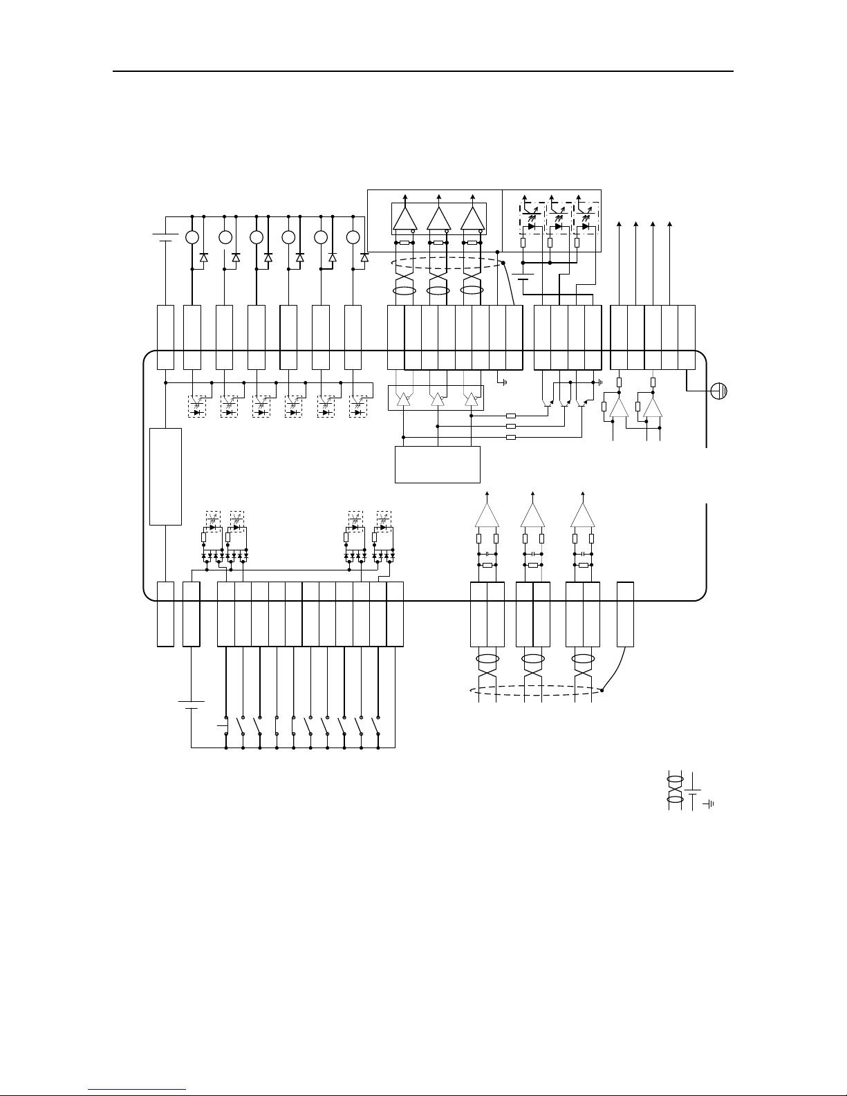
SV-DA200 series AC servo drive Control mode applications
-49-
4.2 Standard wiring of the speed mode
Speed control mode
Load capacity of
each output
terminal is
DC30V, 50mA
EMG 39
SON 16
ZRS 37
POT 3
NOT 4
CLA 10
SPD1 34
SPD2 17
S/SIGN 18
PLC 22
Gain switching
Speed command
symbol
Internal speed
command 2
Internal speed
command 1
Alarm clearing
Negative direction
drive disabled
Emergency stop
Servo enabling
Zero speed clamp
Positive direction
drive disabled
COM- 12
COM+ 2
24V 40
Internal DC24V power
Note: Capacity 100mA
12 COM-
15 ALM
14 RDY
29 ZSO
11 COIN
13 LM
9 BRK
FG
21 AO1
5 GND
25 AO2
6 GND
FG
Torque monitoring output
Speed monitoring output
Fault
Servo ready
Speed zero
Speed matching
Torque limiting
Brake release
Speed command input
(-10V~+10V)
AD1 1
GND 5
When non-standard model is selected, AD1
channel is invalid. Please use AD3 channel
and confirm P3.70 is speed command.
AD2 20
GND 19
AD3 7
GND 8
Analog torque limit of positive direction
(0V~+10V)
Analog torque limit of negative direction
(-10V~0V)
Note: User-supplied power
DC12~24V
- +
Note: User-supplied power
VccDC30V
- +
Frequency
divider
36 OCA
External
controller
44 OA+
43 OA-
41 OB+
42 OB-
FG
26 OCZ
30 OCB
AM26LS32
or equivalent chip
V
cc
DC30V;
OCA/B/Z output
current50mA
28 OZ+
27 OZ-
High speed optical
coupler
35 GND
GND
- +
Vcc
5 GND
CN1
Output voltage range:
DC -10V~+10V;
Max output current:
3mA.
DI input
common port
DO output common
ground
Ref
Note: 1. ( ) is shielded twisted pair;
2. ( ) is power which is provided by the user;
3. ( ) is GND, pin numbers are 5/6/8/19/35.
DO output
common ground
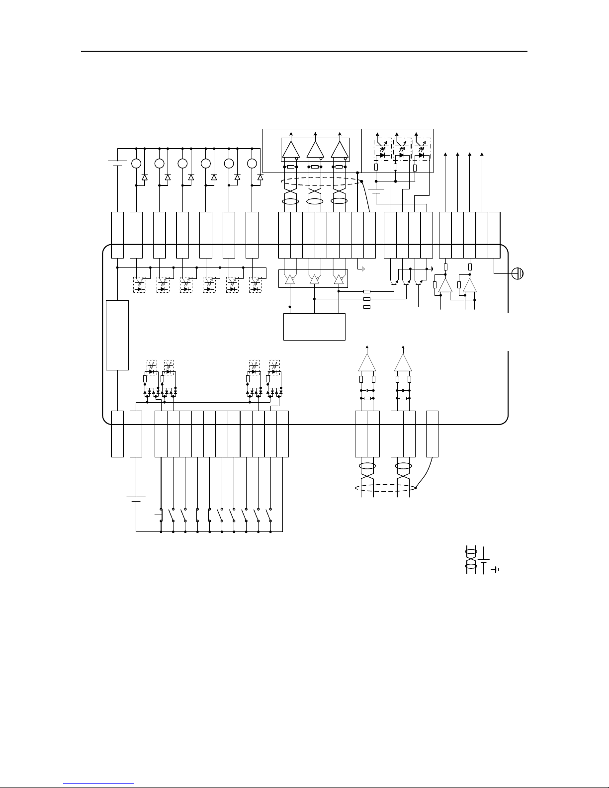
SV-DA200 series AC servo drive Control mode applications
-50-
4.3 Standard wiring of the torque mode
Torque control mode
Speed limit input
(-10V~+10V)
Torque command input
(-10V~+10V)
EMG 39
SON 16
ZRS 37
POT 3
NOT 4
CLA 10
SPD1 34
SPD2 17
T/SIGN 18
PLC 22
Gain switching
Torque command
sign
Internal speed
command 2
Internal speed
command 1
Alarm clearing
Negative direction
drive disabled
Emergency stop
Servo enabling
Zero speed clamp
Positive direction
drive disabled
COM- 12
COM+ 2
24V 40
Internal DC24V power
Note: Capacity 100mA
12 COM-
15 ALM
14 RDY
29 ZSO
11 TRCH
13 LM
9 BRK
AD2 20
GND 19
AD3 7
GND 8
FG
21 AO1
5 GND
25 AO2
6 GND
FG
Torque monitoring output
Speed monitoring output
Fault
Servo ready
Speed zero
Torque reaching
Torque limiting
Brake release
Ref
Max load capacity
of output terminal
is DC30V, 50mA
Note: User-supplied power
DC12~24V
- +
Note: User-supplied power
VccDC30V
- +
Frequency
divider
36 OCA
External
controller
44 OA+
43 OA-
41 OB+
42 OB-
FG
26 OCZ
30 OCB
AM26LS32
or equivalent chip
V
cc
DC30V;
OCA/B/Z
output current
50mA
28 OZ+
27 OZ-
High speed optical
coupler
35 GND
GND
- +
Vcc
5 GND
CN1
Output voltage range:
DC -10V~+10V;
Max output
current:3mA
DI input
common port
DO output common
ground
Note: 1. ( ) is shielded twisted pair;
2. ( ) is power which is provided by the user;
3. ( ) is GND, pin numbers are 5/6/8/19/35.
DO output
common ground

SV-DA200 series AC servo drive Control mode applications
-51-
4.4 CN1 function instruction
4.4.1 Pins of CN1 terminal
CN1 plug pin layout
CN1 plug signal layout
44 43 42 41 40 39 38 37 36 35 34 33 32 31
30 29 28 27 26 25 24 23 22 21 20 19 18 17
15 14 13 12 11 10 9 8 7 6 5 4 3 2161
OA+ OA- OB- OB+ 24V DI4 OCP DI2 OCA GND DI5 SIGN- SIGN+ OCS
OCB DO4 OZ+ OZ- OCZ AO2 PULS- PULS+ DI10 AO1 AD2 GND DI9 DI6
DO2 DO1 DO6 COM- DO3 DI3 DO5 GND AD3 GND GND DI8 DI7 COM+
DI1
AD1
4.4.2 Definition of CN1 terminals
Pin
Sign
Function
Pin
Sign
Function
1
AD1
Analog input 1
23
PULS+
Differential command pulse +
2
COM+
DI input common port
24
PULS-
Differential command pulse -
3
DI7
Digital input 7
25
AO2
Analog output 2
4
DI8
Digital input 8
26
OCZ
Open collector output of Z phase
5
GND
Analog signal ground
27
OZ-
Differential output - of Z phase
6
GND
Analog signal ground
28
OZ+
Differential output + of Z phase
7
AD3
Analog input 3
29
DO4
Digital output 4
8
GND
Analog signal ground
30
OCB
Open collector output of B phase
9
DO5
Digital output 5
31
OCS
Open collector command direction
10
DI3
Digital input 3
32
SIGN+
Differential command direction +
11
DO3
Digital output 3
33
SIGN-
Differential command direction -
12
COM-
DO output common ground
34
DI5
Digital input 5
13
DO6
Digital output 6
35
GND
Analog signal ground
14
DO1
Digital output 1
36
OCA
Open collector output of A phase
15
DO2
Digital output 2
37
DI2
Digital input 2
16
DI1
Digital input 1
38
OCP
Open collector command pulse
17
DI6
Digital input 6
39
DI4
Digital input 4
18
DI9
Digital input 9
40
24V
Internal 24V power supply
19
GND
Analog signal ground
41
OB+
Differential output + of B phase
20
AD2
Analog input 2
42
OB-
Differential output - of B phase
21
AO1
Analog output 1
43
OA-
Differential output - of A phase
22
DI10
Digital input 10
44
OA+
Differential output + of A phase

SV-DA200 series AC servo drive Control mode applications
-52-
4.4.3 Power supply signal
Sign
Pin no.
Name
Function
24V
40
Internal 24V
power supply
COM- is the ground terminal of the 24V power. Its capacity
is 100mA. If the actual load is higher than this value, the
user shall provide the power supply by themselves.
GND
5, 6, 8, 19,
35
Signal ground
The ground of the internal power supply (except the 24V
power supply) of the servo drive, it is also the ground of
the phase A/B/Z open-collector signal of the encoder and
the analog output signal. It is isolated from COM-.
COM+
2
DI input common
port
If DI is active-low (0V), COM+ connects to internal
24V power (pin 40) or external DC power (12V–24V);
If DI is active-high (12V–24V), COM+ connects to the
reference ground of corresponding signal.
COM-
12
DO output
common ground
Local 24V power ground
If external DC power 12V–24V is used, power 0V is
connected to this terminal.
FG
Enclosure
Enclosure ground
The enclosure of CN1 terminal is connected with the
enclosure of the drive
4.4.4 Configuration table for different digital modes
Symbol
Pin
no.
Name
Position mode
Speed mode
Default
value
Mark
Function name
Default
value
Mark
Function name
DI1
16
Digital input 1
0x003
SON
Servo enabling
0x003
SON
Servo enabling
DI2
37
Digital input 2
0x00D
ZRS
Zero speed
clamp
0x00D
ZRS
Zero speed
clamp
DI3
10
Digital input 3
0x004
CLA
Alarm clearing
0x004
CLA
Alarm clearing
DI4
39
Digital input 4
0x016
EMG
Emergency stop
0x016
EMG
Emergency stop
DI5
34
Digital input 5
0x019
SC1
Molecule 1 of
electric gear
ratio
0x00A
SPD1
Internal speed
command 1
DI6
17
Digital input 6
0x01A
SC2
Molecule 2 of
electric gear
ratio
0x00B
SPD2
Internal speed
command 2
DI7
3
Digital input 7
0x001
POT
Positive
direction drive
disabled
0x001
POT
Positive
direction drive
disabled
DI8
4
Digital input 8
0x002
NOT
Negative
direction drive
disabled
0x002
NOT
Negative
direction drive
disabled
DI9
18
Digital input 9
0x007
RPC
Retention pulse
clearing
0x00E
S-SIGN Speed
command sign

SV-DA200 series AC servo drive Control mode applications
-53-
Symbol
Pin
no.
Name
Position mode
Speed mode
Default
value
Mark
Function name
Default
value
Mark
Function name
DI10
22
Digital input 10
0x008
PLL
Command pulse
disabled
0x006
PLC
Gain switching
DO1
14
Digital output 1
0x001
RDY
Servo ready
output
0x001
RDY
Servo ready
output
DO2
15
Digital output 2
0x003
ALM
Fault output
0x003
ALM
Fault output
DO3
11
Digital output 3
0x007
PLR
Positioning
finished
0x009
COIN
Speed matching
DO4
29
Digital output 4
0x00D
ZSO
Speed zero
output
0x00D
ZSO
Speed zero
output
DO5
9
Digital output 5
0x005
BRK
Electromagnetic
brake release
signal
0x005
BRK
Electromagnetic
brake release
signal
DO6
13
Digital output 6
0x00E
LM
Torque limiting
0x00E
LM
Torque limiting
Symbol
Pin
no.
Name
Torque mode
MotionNet mode
Default
value
Mark
Function name
Default
value
Mark
Function name
DI1
16
Digital input 1
0x003
SON
Servo enabling
0x000
OFF
Invalid
DI2
37
Digital input 2
0x00D
ZRS
Zero speed
clamp
0x000
OFF
Invalid
DI3
10
Digital input 3
0x004
CLA
Alarm clearing
0x000
OFF
Invalid
DI4
39
Digital input 4
0x016
EMG
Emergency stop
0x000
OFF
Invalid
DI5
34
Digital input 5
0x00A
SPD1
Internal speed
command 1
0x000
OFF
Invalid
DI6
17
Digital input 6
0x00B
SPD2
Internal speed
command 2
0x103
SON
Servo enabling
DI7
3
Digital input 7
0x001
POT
Positive
direction drive
disabled
0x107
RPC
Retention pulse
clearing
DI8
4
Digital input 8
0x002
NOT
Negative
direction drive
disabled
0x104
CLA
Alarm clearing
DI9
18
Digital input 9
0x00F
T-SIGN Torque
command sign
0x116
EMG
Emergency stop
DI10
22
Digital input 10
0x006
PLC
Gain switching
0x000
OFF
Invalid
DO1
14
Digital output 1
0x001
RDY
Servo ready
output
0x005
BRK
Electromagnetic
brake release
signal
DO2
15
Digital output 2
0x003
ALM
Fault output
0x001
RDY
Servo ready
output

SV-DA200 series AC servo drive Control mode applications
-54-
Symbol
Pin
no.
Name
Torque mode
MotionNet mode
Default
value
Mark
Function name
Default
value
Mark
Function name
DO3
11
Digital output 3
0x010
TRCH
Torque reaching
0x003
ALM
Fault output
DO4
29
Digital output 4
0x00D
ZSO
Speed zero
output
0x007
PLR
Positioning
finished
DO5
9
Digital output 5
0x005
BRK
Electromagnetic
brake release
signal
0x00D
ZSO
Speed zero
output
DO6
13
Digital output 6
0x00E
LM
Torque limiting
0x00E
LM
Torque limiting
4.4.4.1 Function description of the digital input:
Signal name
Sign
Function number
Available mode
Positive direction drive disabled
POT
0x01
P S T
Negative direction drive disabled
NOT
0x02
P S T
This function input is the drive prohibition against positive/negative direction. The concrete action
is related to the setting of P3.40 [travel limit switch setting]:
When P3.40 is set to 0 and positive direction input is disabled, the motor stops at the current
position, only negative direction command input can be accepted. If the negative direction drive
input is disabled, the motor stops at the current position, only positive direction command input
can be accepted.
P3.40 is 1, the function is invalid;
P3.40 is 2, and prohibition of positive/negative drive input is valid, the drive alarms.
Signal name
Sign
Function number
Available mode
Servo enabling
SON
0x03
P S T
This function is the control signal of the servo enabling/disabling.
If it is valid, the drive will provide power to the motor; if invalid, the drive will cut off connection.
Signal name
Sign
Function number
Available mode
Alarm clearing
CLA
0x04
P S T
This function is the control signal of alarm clearing when the drive alarms.
Some alarms cannot be cleared by this function. Please refer to chapter 10.4 for detailed
information.
Signal name
Sign
Function number
Available mode
Control mode switching
MCH
0x05
P S T
This function is the control signal of mode switching when P0.03 is 3, 4 and 5.
When the control mode is 0, 1, 2, 6 and 7 the function input is invalid.
Signal name
Sign
Function number
Available mode
Gain switching
PLC
0x06
P S T
This function is the control signal of 1st and 2nd gain switching.

SV-DA200 series AC servo drive Control mode applications
-55-
Signal name
Sign
Function number
Available mode
Retention pulse clearing
RPC
0x07
P
This function is the control signal of retention pulse clearing and the detailed operation is relative
to the setting of P3.45.
P3.45=0 means electrical level clear. When the digital input is valid, retention pulse will be 0;
P3.45=1 means rising edge clear. When the digital input triggers retention pulse clearing from the
edge of 0→1, only clear once.
Signal name
Sign
Function number
Available mode
Command pulse disabled
PLL
0x08
P
This function is the control signal of stopping receiving the command pulse and the detailed
operation is relative to the setting of P3.44.
P3.44 is 0, the function is valid and when P3.44 is 1, the function is invalid.
Signal name
Sign
Function number
Available mode
Torque limit switching
TLC
0x09
P S
This function is the control signal of 1st and 2nd torque limit switching.
Please refer to the instruction of P0.09.
Signal name
Sign
Function number
Available mode
Internal speed command 1
SPD1
0x0A
S T
Internal speed command 2
SPD2
0x0B
S T
Internal speed command 3
SPD3
0x0C
S
There are 1–8 signal selections for the internal speed command and 1–4 for the internal speed limit.
Control mode
P0.40 setting value
SPD3
SPD2
SPD1
Parameters and setting value
Speed mode
0
0 0 0
P0.46 internal speed 1
0 0 1
P0.47 internal speed 2
0 1 0
P0.48 internal speed 3
0 1 1
P0.49 internal speed 4
1 0 0
P0.50 internal speed 5
1 0 1
P0.51 internal speed 6
1 1 0
P0.52 internal speed 7
1 1 1
P0.53 internal speed 8
Torque mode
0
0 0 0
P0.46 speed limit 1
0 0 1
P0.47 speed limit 2
0 1 0
P0.48 speed limit 3
0 1 1
P0.49 speed limit 4
Signal name
Sign
Function number
Available mode
Zero speed clamp
ZRS
0x0D
S T
This function serves as the control signal of zero speed clamp, refer to P0.58 for detailed
information.

SV-DA200 series AC servo drive Control mode applications
-56-
Signal name
Sign
Function number
Available mode
Speed command sign
S-SIGN
0x0E
S
This function is the sign selection of speed command input in the speed control mode.
If P0.41 is 1, the input function is valid, and when the setting is 0, the function is invalid.
Signal name
Sign
Function number
Available mode
Torque command sign
T-SIGN
0x0F
T
This function is the sign selection of torque command input in the torque control mode.
If P0.61 is 1, the input function is valid, and when the setting is 0, the function is invalid.
Signal name
Sign
Function number
Available mode
Internal position command 1
POS1
0x10
P
Internal position command 2
POS2
0x11
P
Internal position command 3
POS3
0x12
P
Internal position command 4
POS4
0x13
P
Internal position command 5
POS5
0x20
P
Internal position command 6
POS6
0x21
P
Internal position command 7
POS7
0x22
P
These functions are the selections of 0–127 in the PTP (point-to-point) control mode. It has the
same function with P5.20 and is valid when P0.20 is 2.
The combination of 7 digital inputs is used to select the different PTP position of PtP0.00–PtP2.55
and the corresponding target speed, ACC/DEC time and the delay time of P5.21–P5.68.
Control mode
POS7
POS6
POS5
POS4
POS3
POS2
POS1
Parameters and setting value
Position mode
0 0 0 0 0 0 0
PtP0.01[0th position]
0 0 0 0 0 0 1
PtP0.03[1st position]
0 0 0 0 0 1 0
PtP0.05[2nd position]
0 0 0 0 0 1 1
PtP0.07[3rd position]
0 0 0 0 1 0 0
PtP0.09[4th position]
0 0 0 0 1 0 1
PtP0.11[5th position]
0 0 0 0 1 1 0
PtP0.13[6th position]
0 0 0 0 1 1 1
PtP0.15[7th position]
0 0 0 1 0 0 0
PtP0.17[8th position]
0 0 0 1 0 0 1
PtP0.19[9
th
position]
0 0 0 1 0 1 0
PtP0.21[10th position]
0 0 0 1 0 1 1
PtP0.23[11th position]
0 0 0 1 1 0 0
PtP0.25[12th position]
x x x x x x x
xxx
1 1 1 1 1 1 0
PtP2.53[126th position]
1 1 1 1 1 1 1
PtP2.55[127th position]
Signal name
Sign
Function number
Available mode
External fault
EXT
0x14
P S T
This function is the signal of external input fault alarm.

SV-DA200 series AC servo drive Control mode applications
-57-
If the digital input is valid, the drive will report Er10-3 and stop.
Signal name
Sign
Function number
Available mode
Inertia ratio switching
JC
0x15
P S T
This function is the control signal of inertia ratio switching between 1st inertia ratio and 2nd inertia ratio.
When the digital input is valid, the internal software uses P1.02; and when invalid, use P1.01.
Signal name
Sign
Function number
Available mode
Emergency stop
EMG
0x16
P S T
This function is the control signal of emergency stop.
If P3.41 is set to 0 and when the digital input is valid, the drive will stop to report Er10-4.
Signal name
Sign
Function number
Available mode
HOME switch input
HOME
0x17
P
This function is the input signal of HOME SWITCH.
When the drive carries out HOME action, in some HOME mode, if the digital input is detected to
be valid, HOME is finished. Refer to P5.10 for information.
Signal name
Sign
Function number
Available mode
HOME trigger
HTRG
0x18
P
This function is the trigger control signal of HOME function, and the rising edge is valid.
The digital input function has the same function with P5.15.
Signal name
Sign
Function number
Available mode
Molecule 1 of electric gear ratio
SC1
0x19
P
Molecule 2 of electric gear ratio
SC2
0x1A
P
The function is the selection signal of the electric gear ratio, up to 4 groups of electric gears can
be switched.
Before using the function, it is necessary to set P0.22 to 0 and then set different electric gear ratio
(P0.25–P0.29).
Note: If the electric gear is switched by digital value, it is necessary to set P4.10 to 0.
SC1
SC2
Electric gear ratio
Molecule
Denominator
0 0 P0.25
P0.26
1 0 P0.27
P0.26
0 1 P0.28
P0.26
1 1 P0.29
P0.26
Signal name
Sign
Function number
Available mode
PTP control trigger
TRIG
0x1B
P
In the PTP control mode, it needs to be used with internal position command 1–4.
During using, select the target step by the internal position command selection 1–4, and then
trigger the switching action selected by target step via the rising edging of this digital value.

SV-DA200 series AC servo drive Control mode applications
-58-
Signal name
Sign
Function number
Available mode
Vibration control switching input
VS-SEL
0x1C
P
The function is the control signal of 1st and 2nd vibration control frequency.
When the digital input is valid, the internal software uses P1.38; when invalid, use P1.36.
Signal name
Sign
Function number
Available mode
Fast stop
Q-STOP
0x1D
P S T
This function is the control signal of the fast stop of external control.
When the digital input is valid, the motor decelerates to 0 from current speed at the curve set by
P0.69; when the input is invalid, the motor will restore to the operation state before stop.
Signal name
Sign
Function number
Available mode
PTP control stop
PTP-ST
0x1E
P
This function is the control signal of stopping PTP operation in the PTP control mode. In the bus
control mode, it has the same function with P5.20 when it is 2048.
Signal name
Sign
Function number
Available mode
Absolute position clearing
PCLR
0x1F
P
This function is used to clear the multi-turn absolute encoder.
When this digital input is valid, the multi-turn data of the encoder will be cleared while the
single-turn data remains unchanged, however, the absolute position feedback of the system will
be cleared. Signal name
Sign
Function number
Available mode
Forward jogging
FJOG
0x23
P
This function is forward jogging. When this digital input is valid, forward jogging operation will be
applied.
Signal name
Sign
Function number
Available mode
Reverse jogging
RJOG
0x24
P
This function is reverse jogging. When this value is valid, reverse jogging operation will be
applied.
Signal name
Sign
Function number
Available mode
High/low speed switching of jogging
JOGC
0x25
P
This function is high/low speed switching of jogging. When this digital input is valid, high speed
jogging will be applied.
Signal name
Sign
Function number
Available mode
JOG function of the terminal
DJOG
0x2C
P
When this digital input is valid, JOG function of the terminal is valid.

SV-DA200 series AC servo drive Control mode applications
-59-
Signal name
Sign
Function number
Available mode
Gantry synchronization input clear
GIN
0x2D
P
When this digital input is valid, gantry synchronous is removed.
Signal name
Sign
Function number
Available mode
Master gantry synchronization alignment
sensor
GSM
0x2E
P
Master gantry synchronization alignment sensor
Signal name
Sign
Function number
Available mode
Slave gantry synchronization alignment
sensor
GSS
0x2F
P
Slave gantry synchronization alignment sensor
Signal name
Sign
Function number
Available mode
Dynamic braking relay feedback
DBS
0x30
P S T
When this digital input is valid, the dynamic braking relay will be closed.
Signal name
Sign
Function number
Available mode
Manual and automatic switching of turret
DAT
0x31
P
When this digital input is valid, the turret is manual mode.
Signal name
Sign
Function number
Available mode
Forward jogging of turret
DFJ
0x32
P
When this digital input is valid, the turret is forward jogging.
Signal name
Sign
Function number
Available mode
Reverse jogging of turret
DRJ
0x33
P
When this digital input is valid, the turret is reverse jogging.
Signal name
Sign
Function number
Available mode
Switching between fully-closed loop and
semi-closed loop
FCS
0x34
P
This function is valid only when P0.38 [enable fully-closed loop] is set to 2 [enable].
When this digital quantity is valid, it is semi-closed loop; if invalid, it is fully-closed loop
Signal name
Sign
Function number
Available mode
PTP terminal pause
PSTOP
0x35
P
When this digital input is valid, jog control operation pauses.
Signal name
Sign
Function number
Available mode
EzJOG terminal pause
ESTOP
0x36
P
When this digital input is valid, EzJOG operation pauses.

SV-DA200 series AC servo drive Control mode applications
-60-
4.4.4.2 Digital output instruction:
Signal name
Sign
Function number
Available mode
Servo ready output
RDY
0x01
P S T
This function is the state signal of the drive. When valid, the drive can be enabled and provide
power to the motor and when invalid, the drive gives no response to the command.
Signal name
Sign
Function number
Available mode
Servo operation output
RUN
0x02
P S T
This function is the state signal of the enabled drive.
When valid, the motor is power on.
Signal name
Sign
Function number
Available mode
Fault output
ALM
0x03
P S T
The function is the state signal when the drive displays the fault alarm.
When it is valid, the drive has fault.
Signal name
Sign
Function number
Available mode
Electromagnetic brake release signal
BRK
0x05
P S T
The function is the control release signal of output motor brake.
When it is valid, the control brake is released and then it receives the motor control command;
when invalid, the control brake will be disconnected.
Signal name
Sign
Function number
Available mode
Position command or not
PCMD
0x06
P
The function is the state signal of whether there is position command or not.
When it is valid, the motor is controlled by the non-zero position command.
Signal name
Sign
Function number
Available mode
Positioning finished
PLR
0x07
P
The function is the state signal of positioning finished.
When it is valid, the positioning is finished.
Signal name
Sign
Function number
Available mode
Control mode switching
MCHS
0x08
P S T
This function is the state signal during control mode switching in output compound control mode.
When it is valid, control mode 1 is switched to mode 2; if the function output is invalid, the control
mode 2 is switched back to mode 1.
Signal name
Sign
Function number
Available mode
Speed matching
COIN
0x09
P S T
The function is the state signal of speed matching.
When it is valid, the deviation between current speed feedback and speed command is in the
range of P3.53.
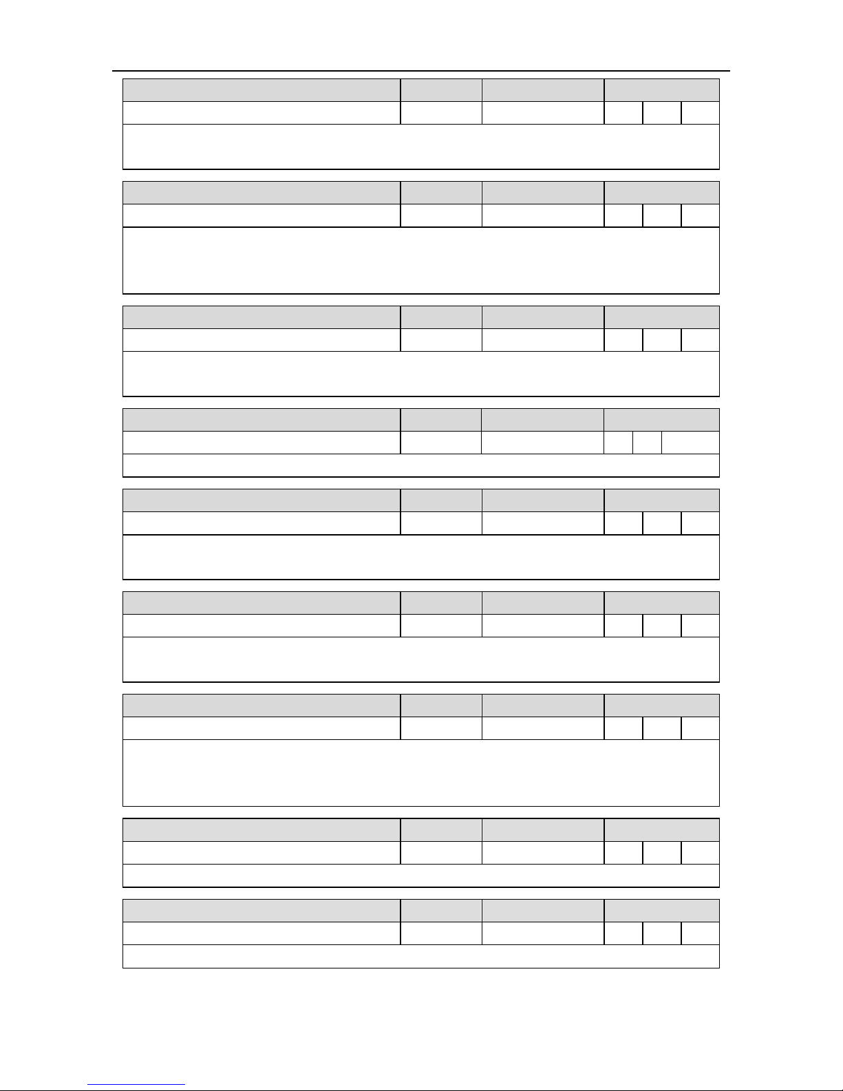
SV-DA200 series AC servo drive Control mode applications
-61-
Signal name
Sign
Function number
Available mode
Speed reaching
SR
0x0A
P S T
The function is the state signal of output speed reaching.
When it is valid, the current speed feedback is in the setting value of P3.54.
Signal name
Sign
Function number
Available mode
Speed limiting
SL
0x0B
T
The function is the state signal of speed limiting.
When it is valid, in the torque mode, if the current torque does not reach the torque command, the
speed feedback is in the speed limiting.
Signal name
Sign
Function number
Available mode
Speed command or not
SCMD
0x0C
P S T
The function is the state signal of whether there is speed command or not.
When it is valid, non-zero speed command controls the motors.
Signal name
Sign
Function number
Available mode
Speed zero output
ZSO
0x0D
P S T
The function is the state signal of whether the current speed feedback is 0.
Signal name
Sign
Function number
Available mode
Torque limiting
LM
0x0E
P S T
The function is the state signal of torque limiting.
When it is valid, it means current torque output has reached the max. torque limit setting.
Signal name
Sign
Function number
Available mode
Zeroing finished
HEND
0x0F
P
The function is the state signal of zero finished.
When it is valid, the drive has finished returning to zero and found zero position successfully.
Signal name
Sign
Function number
Available mode
Torque reaching
TRCH
0x10
T
The function is the state signal of output torque reaching.
When it is valid, the deviation between current torque output and torque command will be in the
setting range of P3.59; there is 5% detection retention.
Signal name
Sign
Function number
Available mode
PTP arrival
PTPF
0x16
P
This function is output PTP arrival signal.
Signal name
Sign
Function number
Available mode
PTP output 1
PTPO1
0x17
P
This function is output PTP output 1 signal.

SV-DA200 series AC servo drive Control mode applications
-62-
Signal name
Sign
Function number
Available mode
PTP output 2
PTPO2
0x18
P
This function is output PTP output 2 signal.
Signal name
Sign
Function number
Available mode
PTP output 3
PTPO3
0x19
P
This function is output PTP output 3 signal.
Signal name
Sign
Function number
Available mode
PTP output 4
PTPO4
0x1A
P
This function is output PTP output 4 signal.
Signal name
Sign
Function number
Available mode
PTP output 5
PTPO5
0x1B
P
This function is output PTP output 5 signal.
Signal name
Sign
Function number
Available mode
PTP output 6
PTPO6
0x1C
P
This function is output PTP output 6 signal.
Signal name
Sign
Function number
Available mode
PTP output 7
PTPO7
0x1D
P
This function is output PTP output 7 signal.
Signal name
Sign
Function number
Available mode
Gantry synchronization output clear
GSC
0x1E
P
This function is to output the clearance signal of gantry synchronization
Signal name
Sign
Function number
Available mode
Dynamic brake relay control
DBRC
0x1F
P S T
This function is output dynamic brake relay control signal.
4.4.5 Pulse input signals and functions
Sign
Pin no.
Name
Function
OCP
38
Position command
pulse input 1
In the position control mode, act as the position
command input terminal.
In other control mode, the terminal is invalid.
Allowed Max. input pulse frequency: 4MHz in
differential motion mode, 200kHz in open-collector
mode.
PULS+
23
PULS-
24
OCS
31
Position command
pulse input 2
SIGN+
32
SIGN-
33

SV-DA200 series AC servo drive Control mode applications
-63-
4.4.6 Analog input signals and functions
Sign
Pin no.
Name
Defaul
t value
Function
name
Function
AD1
1
Analog input 1
0x00
Invalid
Precision of AD1 is 16-bit and precision
of AD2 and AD3 is 12-bit.
If standard model (there is “-S” in the
drive nameplate) is used as the speed
control, AD1 channel is invalid, please
take AD3 as the speed command input
terminal and modify P3.70 to “speed
command”.
External analog input terminals. The
input impedance is 10kΩ. The input
voltage range is -10V–+10V. A voltage
exceeding ±11V may damage the drive.
The range and offset setting and
function definition can be set.
AD2
20
Analog input 2
0x03
Speed
command
AD3
7
Analog input 3
0x04
Torque
command
GND
5, 6, 8,
19, 35
Signal ground
-
-
4.4.7 Encoder output signals and functions
Sign
Pin no.
Name
Function
OA+
44
A phase output
Output the frequency divided encoder signal, comply with
the standard of TIA/EIA-422-B.
The output phase A pulse and phase B pulse is still
quadrature. When it rotates forward, phase B leads phase A
by 90º. When it rotates in reverse, phase A leads phase B
by 90º.
Frequency division and frequency multiplication with any
integer and decimal fraction is allowable.
The output signals have no isolation.
OA-
43
OB+
41
B phase output
OB-
42
OZ+
28
Z phase output
OZ-
27
OCA
36
A phase output
Output the open-collector signal of phase A, without
isolation
OCB
30
B phase output
Output the open-collector signal of phase B, without
isolation
OCZ
26
Z phase output
Output the open-collector signal of phase Z, without
isolation
4.4.8 Analog output signals and functions
Sign
Pin no.
Name
Function
AO1
21
Analog output 1
Its output function definition can be set, and the range and offset
settings can be set.
AO2
25
Analog output 2
Its output function definition can be set, and the range and offset
settings can be set.

SV-DA200 series AC servo drive Control mode applications
-64-
4.5 CN1 wiring instruction
4.5.1 Wiring of digital input circuit
Connection diagram when the power supply is provided by user:
Drive side
2 COM+
12 COM-
DC12~24V
- +
16 DI1
40 24V
Drive side
2 COM+
12 COM-
DC12~24V
- +
16 DI1
40 24V
Drive side
2 COM+
12 COM-
16 DI1
40 24V
Drive side
2 COM+
12 COM-
16 DI1
40 24V
DC12~24V
+ -
DC12~24V
+ -
Active-low Active-high
PNP
NPN
Connection diagram when the local power supply is used:
Drive side
2 COM+
12 COM-
16 DI1
40 24V
Drive side
2 COM+
12 COM-
16 DI1
40 24V
Drive side
2 COM+
12 COM-
16 DI1
40 24V
Drive side
2 COM+
12 COM-
16 DI1
40 24V
Active-low Active-high
NPN
PNP
As shown in above figure, digital input circuit supports mechanical switch connection mode and
open collector connection mode of triode (NPN type and PNP type, mixed-use of these two
types is not allowed);
Users can use either the 24V power supply carried by the servo drive (it only can provide 100mA
current) or 12V–24V power supply provided by the user.
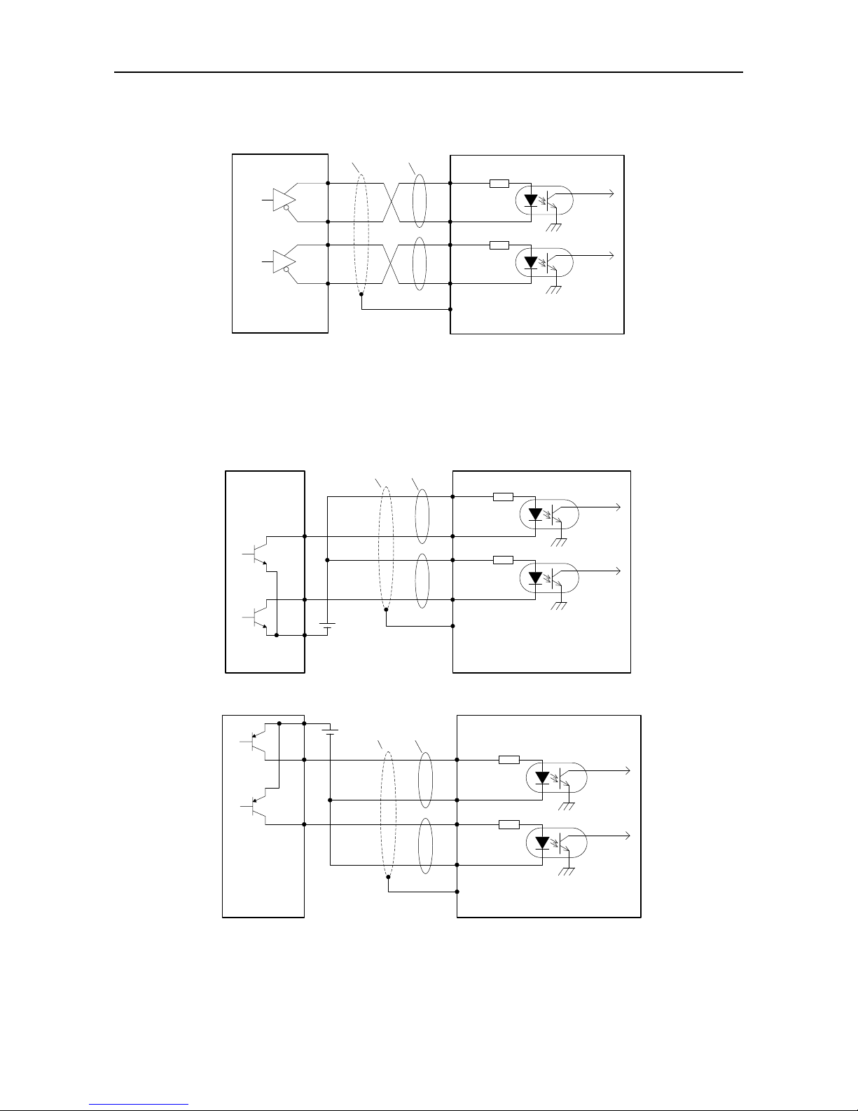
SV-DA200 series AC servo drive Control mode applications
-65-
4.5.2 Wiring of the pulse input circuit
Connect mode 1: Differential mode
Control module side
Shielded
cable
Drive side
23 PULS+
24 PULS-
33 SIGN-
FG
PULS
SIGN
32 SIGN+
Twisted
pair
The maximum frequency of input pulse is 4MHz and the input signal voltage is ±5V;
With the best anti-noise capability, this signal transmit method is recommended as the preferred.
Connection mode 2: Open collector mode 1
The control module is NPN (common cathode)
Control module
side
Drive side
38 OCP
24 PULS-
33 SIGN-
FG
Y1
Y0
PULS
SIGN
31 OCS
+
-
Shielded
cable
Twisted
pair
DC24V
The control module is PNP module (common anode):
Control module
side
Drive side
38 OCP
24 PULS-
33 SIGN-
FG
Y1
Y0
PULS
SIGN
31 OCS
+
-
Shielded
cable
Twisted
pair
DC24V
The max. input pulse frequency is 200kHz; if the local 24V power supply (it only can provide
100mA current) or the 24V power supply provided by the user is used, there is no need to
connect to current limit resistor. Generally, most of Japanese PLC is NPN module, while most of

SV-DA200 series AC servo drive Control mode applications
-66-
European PLC is PNP module.
Connection mode 3: Open collector mode 2
The control module is NPN (common cathode):
Control module
side
Drive side
23 PULS+
24 PULS-
33 SIGN-
FG
Y1
Y0
PULS
SIGN
32 SIGN+
+
-
R
R
Shielded
cable
Twisted
pair
DC12~24V
The control module is PNP (common anode):
Control module
side
Drive side
23 PULS+
24 PULS-
33 SIGN-
FG
Y1
Y0
PULS
SIGN
32 SIGN+
+
-
R
R
Shielded
cable
DC12~24V
Twisted
pair
The input pulse frequency is 200kHz; if the local 24V power supply (it only can provide 100mA
current) or the 12–24V power supply provided by the user is used, it is required to connect to
current-limiting resistor R(the resistance is selected as the below table).
VDC-1.5
R+68
10(mA)
VDC R parameter
12V 1kΩ,1/4W
24V 2kΩ,1/3W
For all the 3 methods, shielded twisted-pair must be used and the length should be less than 3m.
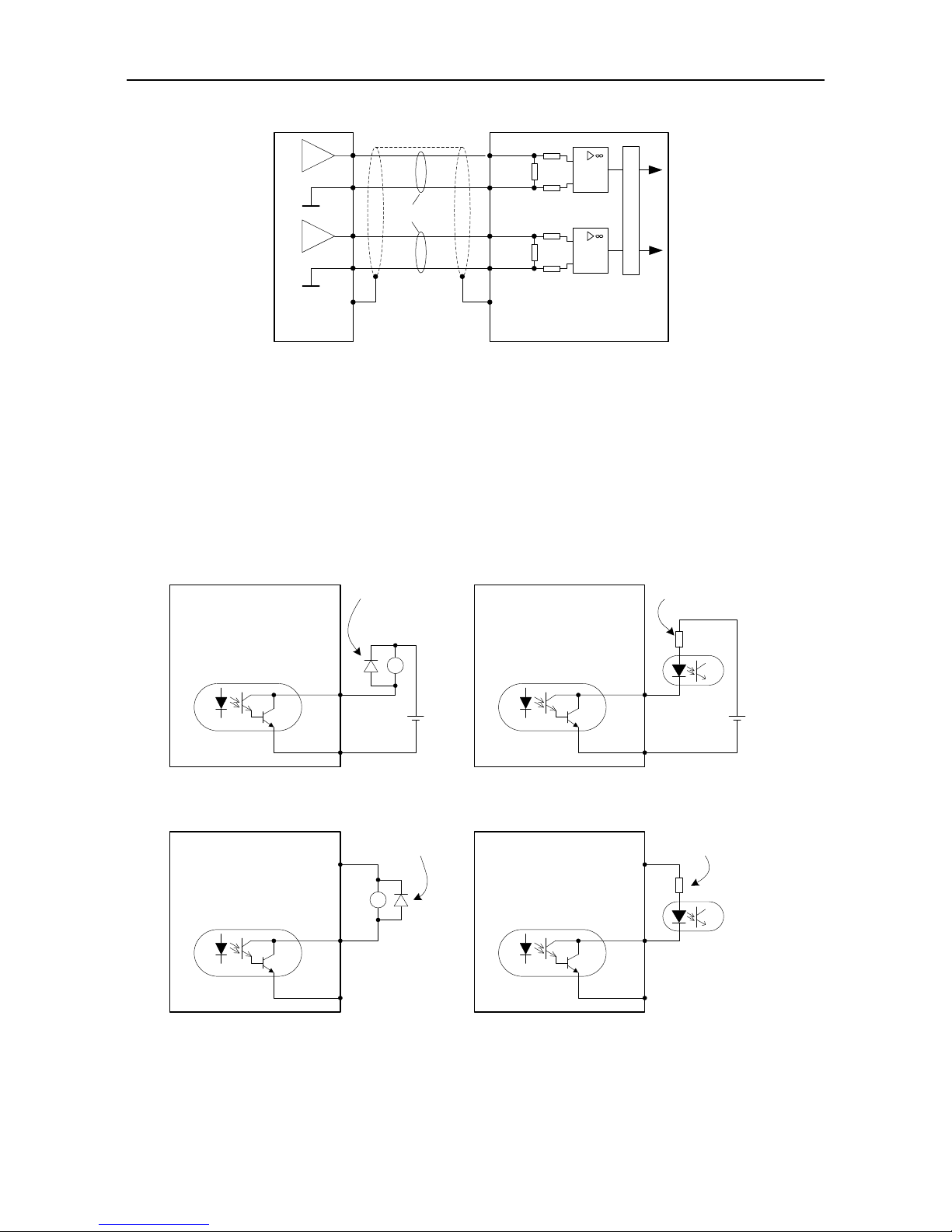
SV-DA200 series AC servo drive Control mode applications
-67-
4.5.3 Wiring of the analog input circuit
0
0
0
1 AD1
5 GND
20 AD2
A
D
C
FG
Please connect shielded
cable according to the
device requirement
Twisted
pair
19 GND
0
0
0
Drive side
Control module
side
There are three analog input circuits, AD1, AD2 and AD3, precision of AD1 is 16-bit (optional for
standard models), precision of AD2 and AD3 is 12-bit (standard). The input impedance is 10kΩ.
The input voltage range is -10V–+10V. If the voltage is higher than ±11V, the circuits may be
damaged.
If the non-standard model is used as the speed control, AD1 channel is invalid, please take AD3
as the speed command input terminal and modify P3.70 to “speed command”.
4.5.4 Wiring of digital output circuit
Connection diagram when the power supply is provided by user:
Users must install this
freewheeling diode when
connecting to inductive load
Max load capacity of each
output terminal: 30V, 50mA.
DC
12~24V
+
-
Drive side
DO1 14
COM- 12
Max load capacity of each
output terminal: 30V, 50mA.
+
-
RY
DC
12~24V
connect to relay coil
connect to optical coupler
DO1 14
COM- 12
Users must connect to current
limit resistor when connecting
to optical coupler
Drive side
Connection method when the local power supply is used:
Users must install this
freewheeling diode when
connecting to conductive load
Max load capacity of each
output terminal:
30V, 50mA.
Drive side
DO1 14
COM- 12
Max load capacity of each
output terminal:
30V, 50mA.
RY
connect to relay coil
connect to optical coupler
DO1 14
COM- 12
Users must connect to current
limit resistor when connecting
to optical coupler
Drive side
24V 40 24V 40
There are 6 digital output circuits in total and all of them adopt the open-collector output as
shown in the figure. They can be used to drive the relay coil or optical coupled load. The loading
capacity is shown in the figure.

SV-DA200 series AC servo drive Control mode applications
-68-
When inductive loads such as relay coil are connected, a free wheel diode must be fitted as
shown in the figure; when optical coupler is connected, current limit resistor must be connected,
otherwise the drive will be damaged.
The local 24V power supply only can provide 100mA current. If the actual load current is larger
than 100mA, the user should provide the power supply by themselves. The recommended
capacity is greater than 500mA.
4.5.5 Wiring of frequency division output circuit of encoder feedback signal
Differential mode:
Drive side
OA+ 44
OA- 43
OB+ 41
OB- 42
OZ+ 28
OZ- 27
GND 5
Twisted
pair
Terminal
resistor
AM26LS32
or equivalent chip
GND
Shielded
cable
Connect to shielded
cable according to
device requirement
Open-collector mode:
Output current 50mA
OCZ 26
Please select optical
coupler
Twisted pair
Drive side Control module side
+
-
OCA 36
OCB 30
GND 5
Vcc
30V
GND
Phase A, B and Z all provide differential output and open-collector output signals.
For differential output signal, it is recommended to use AM26C32 or equivalent differential
receiving chip and be sure to fit a terminal matching resistor of about 220Ω.
For the phase A, B, Z signal of open-collector output, as the signal pulse width is very narrow,
the user shall use high speed optical coupler to receive this signal.
Both output circuits have no isolation.
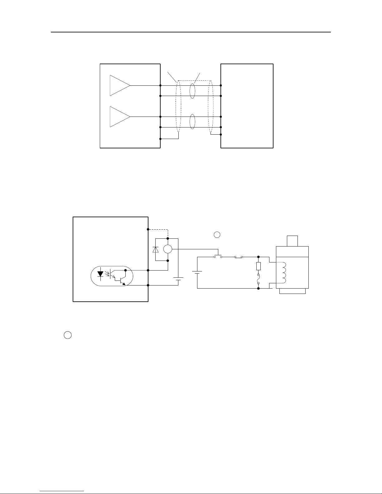
SV-DA200 series AC servo drive Control mode applications
-69-
4.5.6 Wiring of the analog output circuit
AO1 21
AO2 25
GND 5
GND 5
GND
GND
AI1
AI2
FG
Measuring instruments or
external circuit
Shield cable
Twisted pair
Connect the shield cable
according to the
requirement
Servo drive
There are two analog output circuits in all. The output voltage range is -10V–10V. The Max
output current is 3mA.
4.5.7 Wiring of the electromagnetic brake
If the servo drive is used in the vertical shaft applications, the electromagnetic brake can be used to
stop and keep the dropping speed when servo drive is power off. The wiring diagram is:
DC12~24V
external power
COM- 12
BRK 9
Connect the dotted lines in
the diagram when local 24V
power is used, and remove
the external power.
Motor
Brake
winding
Surge
absorber
Fuse (5A)
E-stop button
RY
DC24V
power
specific for
brake winding
24V 40
Note: Brake winding must use specific 24V power,
and it cannot be used in common with control power
or relay coil power.
+
-
+
-
Drive side
RY
RY
24V power supply specific for the electromagnetic brake cannot be used with the power supply for
control signal;
RY
is the relay coil, please pay attention to the direction of the diode;
The electromagnetic brake is used to keep the speed, other than stop;
Please install the external braking devices besides the electromagnetic brake.

SV-DA200 series AC servo drive Control mode applications
-70-
4.6 CN5 wiring diagram
4.6.1 CN5 wiring diagram of small power range (100W–5.5kW)
2nd encoder and STO
Differential command pulse input
(Max 4Mpps)
EXA+ 3
EXA- 4
EXB+ 10
EXB- 9
EXZ+ 14
- +
EXZ- 13
FG
HWBB1+ 1
HWBB1- 7
HWBB2+ 2
HWBB2- 8
WheN S1 set To ON, sAfetY
input termiNal signaL is
inValId, anD sErvo can Work
Normally; when S1 is set to
OFF, the servo can work
normally only if the safety
input terminal signal is valid
at the same time.
- +
HWBB1+ 1
HWBB1- 7
HWBB2+ 2
HWBB2- 8
S1STO switch
5 EX5V
12 EX0V
EX0V
EX5V
Safety terminal signal is active-low
Safety terminal signal is active-high
CN5
6 EDM+
11 EDM-
+ -
Safety output signal is active-high
Safety output signal is active-low
6 EDM+
11 EDM-
+ -
Note: 1. ( ) is shielded twisted pair;
2. ( ) is power source, DC12~24V which
is prepared by the user.

SV-DA200 series AC servo drive Control mode applications
-71-
4.6.2 CN5 wiring diagram of medium power range (7.5kW–55kW)
2nd encoder and STO
Differential command pulse input
(Max 4Mpps)
EXA+ 1
EXA- 2
OC_EXA 19
2kΩ
EXB+ 3
EXB- 4
OC_EXB 18
2kΩ
OC_EXZ 17
24V power, built-in current limit resistor
12~24V power, connects to external
current limit resistor
VDC12~24V
VDC24V
R
R
VDC-1.5
R+68
10mA
Note: The max input of open collector is 200kpps
12V 1k,1/4W
24V 2k,1/3W
EXZ+ 5
13 EDM+
14 EDM-
- +
EXZ- 6
FG
HWBB1+ 11
HWBB1- 12
HWBB2+ 15
HWBB2- 16
2kΩ
OC_EXZ 17
EXZ- 6
EXB- 4
OC_EXB 18
EXA- 2
OC_EXA 19
FG
EXA+ 1
EXA- 2
EXB+ 3
EXB- 4
EXZ+ 5
EXZ- 6
R
FG
When S1 is set to ON, safety
input terminal signal is
invalid, servo can work
normally; when S1 set to
OFF, the servo can work
normally only when safety
input terminal signal is valid.
- +
HWBB1+ 11
HWBB1- 12
HWBB2+ 15
HWBB2- 16
S1: STO switch
7/9 EX5V
8/10 EX0V
EX0V
EX5V
Safety terminal signal is active-low
Safety terminal signal is active-high
+ -
Safety output signal is active-high
Safety output signal is active-low
13 EDM+
14 EDM-
+ -
CN5
+
-
+
-
Note: 1. ( ) is shielded twisted pair;
2. ( ) is power source, DC12~24V which
is prepared by the user.
V
DC
R parameter
4.6.3 2nd encoder input circuit wiring of medium power range (7.5kW–55kW)
Connection mode 1: Differential mode
Control module side
Shielded cable
Drive side
1 EXA+
2 EXA-
FG
EXA
Twisted pair
4 EXB-
3 EXB+
6 EXZ-
EXZ
5 EXZ+
EXB
Differential pulse input signal voltage is ±5V, max frequency is 4MHz;
Such signal transmission mode has optimal anti-noise capacity, it is recommended to take this
connection mode as priority.
Connection mode 2: Open collector mode 1

SV-DA200 series AC servo drive Control mode applications
-72-
Control module is NPN type (common cathode):
Control module
side
Drive side
19 OC_EXA
2 EXA-
FG
Y0
EXA
EXB
18 OC_EXB
Shielded cable Twisted pair
4 EXB-Y1
6 EXZ-
Y2
+
-
DC24V
EXZ
17 OC_EXZ
Control module is PNP type (common anode):
Control module
side
Drive side
FG
Y1
Y0
EXA
EXB
+
-
Shielded cable Twisted pair
DC24V
Y2
EXZ
19 OC_EXA
2 EXA-
18 OC_EXB
4 EXB-
6 EXZ-
17 OC_EXZ
Max input pulse frequency is 200kHz; if the local 24V power of DA200 (only 100mA power is
available) or the 24V power provided by the user is used, there is no need to connect current
limit resistor. Generally, PLC of Japanese brands mainly adopts NPN type while PLC under
European brands mainly adopts PNP type.
Connection mode 3: Open collector mode 2

SV-DA200 series AC servo drive Control mode applications
-73-
Control module is NPN type (common cathode):
Control module
side
Drive side
1 EXA+
2 EXA-
FG
Y0
3 EXB+
Shielded
cable
Twisted
pair
4 EXB-Y1
6 EXZ-
Y2
+
-
5 EXZ+
DC12~24V
R
R
R
EXA
EXB
EXZ
Control mode is PNP type (common cathode):
1 EXA+
2 EXA-
3 EXB+
4 EXB-
6 EXZ-
5 EXZ+
Control module
side
Drive side
FG
Y1
Y0
+
-
Shielded
cable
Twisted
pair
Y2
R
R
R
DC12~24V
EXA
EXB
EXZ
Max input pulse frequency is 200kHz; if the local 24V power of DA200 (only 100mA power is
available) or the 24V power provided by the user is used, it is required to connect to current limit
resistor R.
VDC-1.5
R+68
10(mA)
VDC R parameter
12V 1kΩ,1/4W
24V 2kΩ,1/3W
These three connection modes all require shielded twisted pair whose length should be less than 3m.

SV-DA200 series AC servo drive Running and operation
-74-
5 Running and operation
5.1 Running
5.1.1 First powering on
Please check following items before power on:
1) Wiring
The power supply of the servo drive (L1, L2, L3, L1C, L2C or R, S and T) should be connect to
proper techniques; see chapter 3.2 for details;
The output phase of the servo drive (U, V and W) should be the same as that of the cables of the
servo motor;
There is no short circuit between the output of the servo drive (U, V and W) and the input power
supply (L1, L2, L3, R, S and T);
All wiring comply with the standard wiring shown in chapter 4;
Ensure the external terminal (SON) for servo enabling is set to OFF;
Ensure the servo drive and the servo motor are grounded to properly;
When using external braking resistor, for products with small power range, the short connection
cable between B2-B3 must be removed;
Do not put voltage above DC24V on CN1;
The cable stress is within the designated range.
2) Environment
There are no foreign objections, such as metal and other wire lead which can cause short
connection of signal and power wires.
3) Mechanical parts
The installation of the servo motor and the connection of shafts and mechanics are reliable;
The servo motor and the machines are available to run;
Do not run the motor at negative load (the direction of the output torque of the motor is contrary
to the motor speed direction).
If all above items are checked OK, switch on the power supply:
5.1.1.1 Sequence of powering ON/OFF
The control circuit and the main circuit of the drive are supplied separately. In principle, when
powering on, switch on the power supply of the control circuit (terminals L1C, L2C) first and then
switch on the power supply of the main circuit (terminals L1, L2, L3). When powering off, switch off the
power supply of the main circuit first and then switch off the power supply of the control circuit.
After switching on the control circuit power supply and before switching on the main circuit power
supply, R0.30 will display "0” and after power on of the main circuit, R0.30 will display "2” and the
servo drive can be enabled.
For product with medium power range (7.5kW–55kW), please connect to main circuit 3PH power (R,
S and T terminals).

SV-DA200 series AC servo drive Running and operation
-75-
5.1.1.2 Checking after powering-on
After switching on both of the control circuit and main circuit power supplies, if the power supply is OK,
the LED indicator will display 0 first and then display 8. If there is no fault alarm of the servo drive, the
LED on the front panel displays the current speed of the servo motor as default. The default
parameter can be set through parameter P0.15. If there is a fault of the servo drive, the LED displays
current alarm sign and flickers. Please fix the fault by referring to chapter 9.
5.1.1.3 Set the motor code
Before enabling operation, please set P0.00 according to the motor code on motor nameplate,
otherwise, the motor may operate abnormally or reversely and cause safety issues.
5.1.2 Trial jogging
Trial jogging can check whether the servo drive and the servo motor are intact and conduct
preliminary debugging of the system including the servo drive, servo motor and peripheral equipment.
Run the servo motor by JOG operation after ensuring that the wiring is correct and there is no fault
alarm and no abnormal running, See chapter 5.2.5 for detailed instructions. Before jog running,
ensure:
The motor isn’t in running state. If the motor is running, JOG operation is invalid;
The load inertia shouldn’t exceed 15 times of the motor inertia. Otherwise it may cause serious
mechanical vibration;
The jog speed can be set via parameter P0.05.
The accelerating/decelerating time during jogging can be set via parameters P0.54, P0.55 and
P0.56, P0.57.
5.1.3 Running at the position control mode
Simple connection:
DC
12~24V
PULSE+ 23
PULSE- 24
SIGN+ 32
SIGN- 33
FG
Upper
pulse
generator
Servo drive
CN1
SON 16
COM+ 2
Parameter
Function
Setting value
P0.031
Control mode selection
0
P0.221
Pulse number per motor
resolution
Set according to
the requirement
P0.231
Pulse input
Set according to
the requirement
P0.241
Reverse of pulse input
direction
0
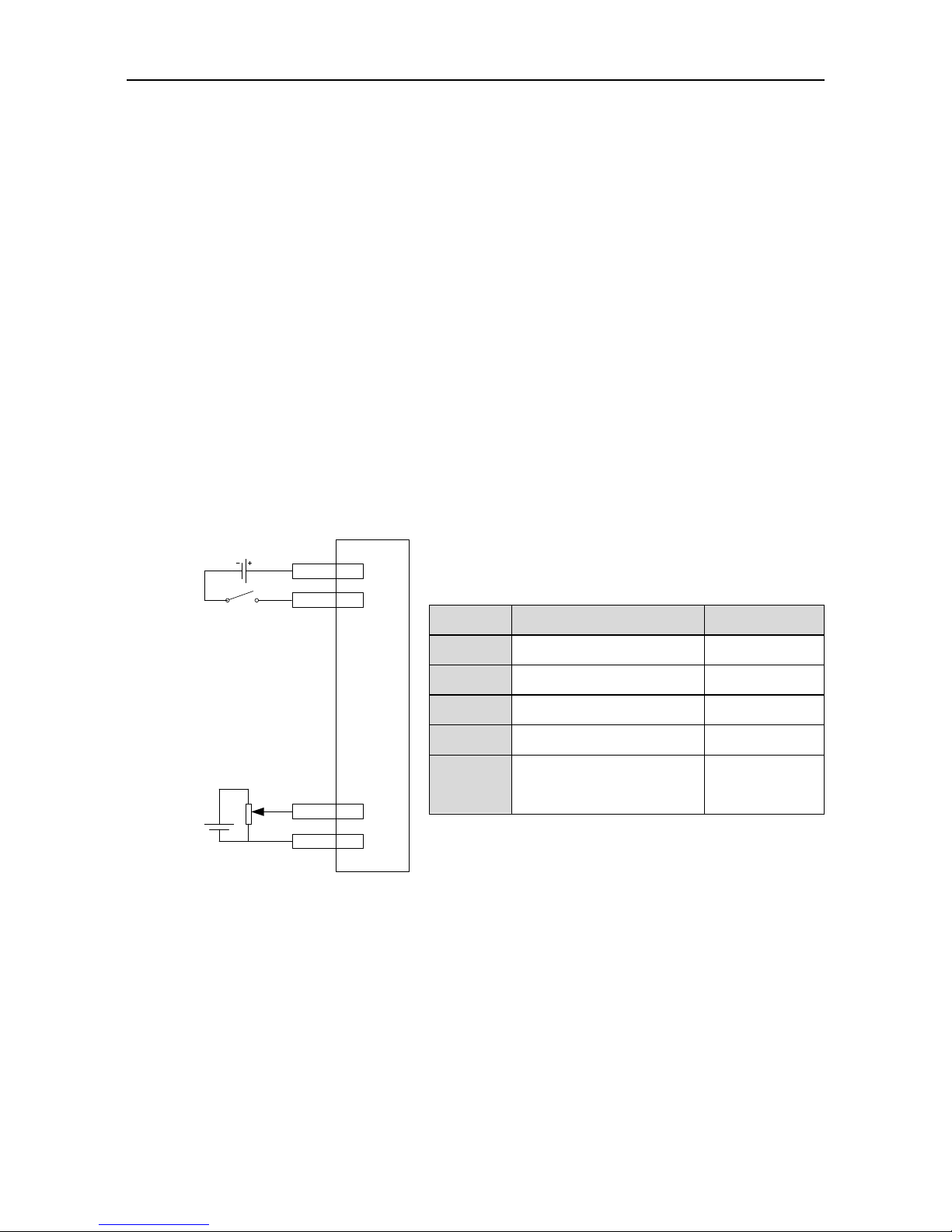
SV-DA200 series AC servo drive Running and operation
-76-
Steps:
1. Complete the connection between the drive and the servo motor.
2. Set P0.03 to “0”, the position control mode.
3. Confirm the pulse output of the upper controller and adjust P0.23. Keep the pulse type the
same with that of the upper controller. Please refer to the instruction of P0.23.
4. Disconnect the control power supply after the modification of P0.03, P0.23 and then power
on again.
5. Connect CN1 to the drive and apply the power supply. Control the connection between SON
and COM-. And then, the servo enters into the locking state.
6. Send the low frequency pulse command from the upper controller and rotate the motor at low
speed.
7. Ensure the rotating direction of the motor is as the designated. The direction can be modified
through the upper controller or operate on P0.24.
8. Ensure the pulse number is as the designated. Please refer to the instruction of P0.22, P0.25
and P0.26.
5.1.4 Running at the speed control mode
Simple connection
DC
12~24V
Servo drive
CN1
Speed
command for
upper analog
0~±10V
+
-
SON 16
COM+ 2
AD1 1
GND 5
Steps:
1. Complete the connection between the drive and the servo motor.
2. Set P0.03 to “1”, the speed control mode.
3. It is necessary to disconnect the control power supply after saving the modified value of
P0.03. And it will be valid after repowering on.
4. Set P0.40 to “1”, external analog speed command mode.
5. Set P3.26 to “3”, analog input 1 is speed command;
6. Set P0.42 to the required value. Please refer to the instruction of P0.42.
7. Connect the corresponding terminals of CN1.
8. Connect the CN1 to the drive and power on. Control the connection between SON and
Parameter
Function
Setting value
P0.031
Control mode selection
1
P0.40
Speed command selection
1
P3.26
Function of analog input 1
3
P0.42
Analog input 1 gain
500
P3.20
Analog speed command
offset
Set according to
the requirement

SV-DA200 series AC servo drive Running and operation
-77-
COM-. Then the servo enters into the locking state.
9. The motor shaft may rotate at a low speed if there is no upper command voltage. It is
necessary to adjust P3.20. Please refer to the detailed instruction of P3.20.
5.1.5 Running at the torque control mode
Simple connection:
SON 16
COM+ 2
DC
12~24V
AD2 20
GND 5
Servo drive
CN1
+
-
Torque
command for
upper analog
0~±10V
Steps:
1. Complete the connection between the drive and the servo motor.
2. Set P0.03 to “2”, the torque control mode.
3. It is necessary to disconnect the control power supply after saving the modified value of
P0.03. And it will be valid after repowering on.
4. Set P0.60 to “1”, external analog torque command mode.
5. Set P0.61 to the required value. Please refer to the instruction of P0.61.
6. Set P3.26 to “4”, analog input 1 is torque command;
7. Set P0.62 to the required value. Please refer to the instruction of P0.62.
8. Connect the corresponding terminals of CN1.
9. Connect the CN1 to the drive and power on. Control the connection between SON and
COM-. Then the servo enters into the locking state.
10. The motor shaft may rotate at a low speed if there is no upper command voltage. It is
necessary to adjust P3.23. Please refer to the detailed instruction of P3.23.
11. In the torque mode, please adjust the speed limit and set P0.46 to the required value. Please
refer to the detailed instruction of P0.46.
5.1.6 Parameter setting before running the servo
Parameter setting must be conducted before running the servo. Relevant parameters can be set via
the panel, PC software or communication to meet the function and performance requirements of the
site application. See chapter 6 for the detailed description of all parameters of the servo drive. Some
Parameter
Function
Setting value
P0.031
Mode selection
2
P0.60
Torque command
selection
1
P3.27
Function of analog
input 2
4
P0.61
Torque command
direction selection
Set according to
requirement
P0.62
Analog input 2 gain
10
P3.23
Analog input 2 offset
Set according to
requirement
P0.46
Speed limit 1
100

SV-DA200 series AC servo drive Running and operation
-78-
of these parameters need to be set according to the site application demand. For examples, pulse
input mode, electronic gear, frequency division coefficient of encoder output, upper/lower limit of
analog input, etc. Some of these parameters need to be set according to the site debugging. For
example, the parameters of the regulator loop which affect the system performance and other similar
parameters. For most parameters the factory default values are appropriate.
Hereunder only some necessary parameters are listed:
1) Mode setting
The control mode (position mode, speed mode, torque mode or other compound control mode) can
be set through setting parameter P0.03 according to the control requirements on the site. The mode
will be valid after repowering on.
2) Command input
Set or enter relevant commands to control the position, speed or torque of the servo motor’s shaft
according to the setting of parameter P0.03.
In the position mode: pulse command (3 kinds of input mode), internal torque limit command or
external analog torque limit command;
In the speed mode: internal speed command or external analog speed command, internal torque
limit command or external analog torque limit command;
In the torque mode: internal torque command or external analog torque command, internal
speed limit command or external analog speed limit command.
5.1.7 Servo enabling
Enable the servo via the external servo enabling terminal (SON) or internal servo enabling parameter
(P0.04). See the function description of terminal SON and detailed explanation of parameter P0.04.
When servo enabling:
If no alarm occurs, the panel will display the default monitoring parameters;
The fan starts to run;
In position mode, if there is no pulse command input, the servo is in locked state;
In the speed mode, the servo motor runs at the given speed;
In the torque mode, if no torque is applied externally, the servo motor accelerates from zero
speed to the limit speed. If the external torque is larger than the internal setting one, the servo
motor maintains the state of zero speed output;
If a servo alarm occurs, the panel will display ErXX-X and flicker and the servo motor will get into
the inertia running state.
5.1.8 Servo stop/Stop running
If the servo drive is in the following conditions, the servo motor will coast to stop or stop normally.
Coasting to stop means the drive cuts off output immediately, the motor coasts to stop under the
action of inertia, and does not keep in locked state. Stopping means the drive outputs reverse torque
to make the motor to decelerate to zero speed and, after that, the motor is in a locked state.
When the servo enabling terminal (SON) signal is set to OFF, the servo motor will stop. Select

SV-DA200 series AC servo drive Running and operation
-79-
the stopping method through setting parameter P4.30. See description of P4.30 for details. This
process will not cause regenerative braking.
When a fault alarm occurs, the servo motor will stop. Select the stopping method of the servo
motor when an alarm occurs through setting parameter P4.30. See description of P4.30 for
details. This process will not cause regenerative braking.
When the digital input terminal configured as zero speed clamp (ZRS) is set to ON and P0.58 is
at non-zero value, the servo motor stops running. When P0.58 is set to 1–3, the motor stops
running based on the DEC time set by P0.55 and P0.57 in speed mode, and servo is in locked
state after stop; in torque mode, the servo motor stops running immediately. Such stopping
process may cause regenerative braking. If braking overload fault alarm occurred, please
connect to proper external braking resistor.
If the travel limit switch block function is invalid (parameter P3.40=0), and digital input terminal
signal configured as travel limit (POT/NOT) is set to ON, P0.55 and P0.57 of the servo motor
will immediately decelerate to stop based on the set value of P0.55 and P0.57. it will be in
locked state after stop. If reverse running command input is generated after motor stops, the
motor can run in reverse direction.
If the emergency stop switch block function is invalid (parameter P3.41=0), and the digital input
terminal configured as EMG is set to ON, the servo motor will coast to stop.
If the duration of servo disable signal is too short (less than 500ms), PWM signal may be in off
state once servo is enabled again.
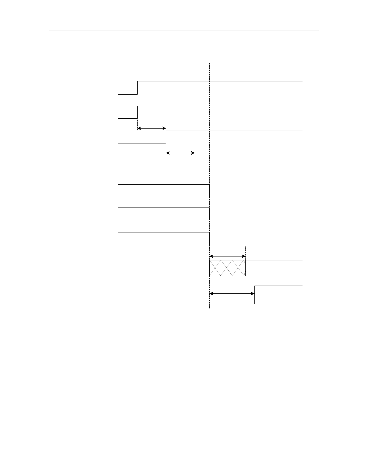
SV-DA200 series AC servo drive Running and operation
-80-
5.1.9 Sequence diagram
5.1.9.1 Sequence diagram of power-on and servo ON
Main power
Control power
PWM output
Electromagnetic
brake release signal
output (BRK)
Servo enable
(SON)
Microprocessor state
Note 1: The delay time from the completion of microprocessor initialization to the readiness of servo output
can be set via P4.54;
Note 2: The condition for the RDY output signal electric leveL to become low is: servo has no fault and main
circuit DC voltage has been established (voltage is higher than 250V/430V (220V series/400V series));
when the main circuit DC voltage is less than 170V/310V (220V series/400V series), Er13-1 alarm will
occur. The time interval from the readiness of servo and enabling of servo can be controlled by users;
Note 3: The servo enable signal can become valid only when RDY output signal is valid;
Note 4: The actual electric level corresponding to the IO valid state can be set via P3.00~P3.15.
Position/speed/torque
command input
About 1.2s
Note 3
100ms
Control circuit power-on
Main circuit power-on
Program starts running
Servo has no output
Motor brake releaseMotor brake
Servo has output
Command input invalid Command input valid
Fan signal
Fan operating
Fan does not operate
Power-on process Servo On process
100ms
Program initialization
Servo ready state
(RDY)
Note 2
Note 1
Invalid
Invalid
Valid
Valid
Note 4
Brake is
releasing
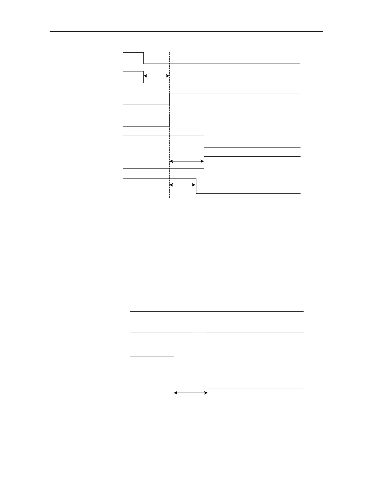
SV-DA200 series AC servo drive Running and operation
-81-
5.1.9.2 Sequence diagram of power loss during running
Main power
Control power
PWM output
Electromagnetic
brake release signal
output (BRK)
Servo ready output
(RDY)
Microcontroller state
Note 1: If the voltage of the control circuit is less than 170V/330V(220V series/400V series), the
undervoltage fault will occur and the output level of the servo fault (ALM) will increase;
Note 2: If the drive temperature is less than 45 , the fan stops, if the drive temperature is higher than
45 , the fan will stop after the micro processor stops;
Note 3: The output delay of electromagnetic brake release signal is set by P3.57; if the speed slows
down to the setting value of P3.58 (30r/min by default) during the time set by P3.57, BRK signal will
become invalid;
Note 4: The actual level corresponding to input/output valid state can be set by P3.00~P3.15
Note 1
Control circuit power disconnection
Main circuit power loss
Program stops running
Servo has output
Motor brakeMotor brake-release
Servo has no output
Fan signal Fan stops runningFan running
Note 2
Note 3
Valid Invalid
Program running
Note 4
5.1.9.3 Servo OFF sequence in a locked state
Dynamic brake state
PWM output
Electromagnetic
brake release signal
output (BRK)
Servo ready output
(RDY)
Servo fault output
(ALM)
Servo enabling (SON)
Note 1: The startup of dynamic brake can be set by P4.30;
Note 2: The servo locking time after braking can be set by P3.56;
Note 3: The actual electric level corresponding to I/O valid state can be set by P3.00~P3.15.
No fault alarm
Servo has output
Motor brakeMotor brake-release
Servo has no output
Dynamic brake switches onNote 1
Note 2
Normal
Dynamic brake
switches off
Enable Disable
Note 3

SV-DA200 series AC servo drive Running and operation
-82-
5.1.9.4 Servo OFF sequence in running state
Dynamic brake state
PWM output
Electromagnetic
brake release signal
output (BRK)
Servo ready output
(RDY)
Servo fault output
(ALM)
Servo enabling (SON)
Note 1: The switch on/off of the dynamic brake can be controlled by P4.30;
Note 2: The output delay of electromagnetic brake release signal is set by P3.57; if the speed is less than
the setting value of P3.58 during the time of P3.57, the BRK signal will become invalid;
Note 3: The actual electric level corresponding to input/output valid state can be set by P3.00~P3.15.
No fault alarm
Servo has output
Motor brakeMotor brake-release
Servo has no output
Dynamic brake switches onNote 1
Note 2
Enable Disabled
Valid
Dynamic brake
switches off
Note 3
5.1.9.5 Sequence of fault alarm
Dynamic brake state
PWM output
Electromagnetic
brake release signal
output (BRK)
Servo ready output
(RDY)
Servo fault output
(ALM)
Note 1: The switch on/off of the dynamic brake can be controlled by P4.30;
Note 2: The output delay of electromagnetic brake release signal is set by P3.57; if the speed is less than
the setting value of P3.58 during the time of P3.57, the BRK signal will become invalid;
Note 3: The actual electric level corresponding to input/output valid state can be set by P3.00~P3.15.
Fault alarm
Servo has output
Motor brakeMotor brake-release
Servo has no output
Dynamic brake switches onNote 1
Note 2
Dynamic brake
switches off
Normal
Valid Invalid
Note 3
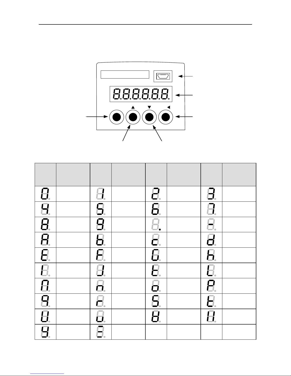
SV-DA200 series AC servo drive Running and operation
-83-
5.2 Display and operation
5.2.1 Display
Keypad diagram:
MODE key
Display
SET/SHIFT key
UP key DOWN key
USB port
MODE SET/
C
N
4
LED display character (reference table):
LED
display
character
Corresponding
symbol
LED
display
character
Corresponding
symbol
LED
display
character
Corresponding
symbol
LED
display
character
Corresponding
symbol
0 1 2
3
4 5 6
7
8 9 .
-
a b c
d
e f g
h
i j k
l
m n o p q r s
t
u v w
x
y
z
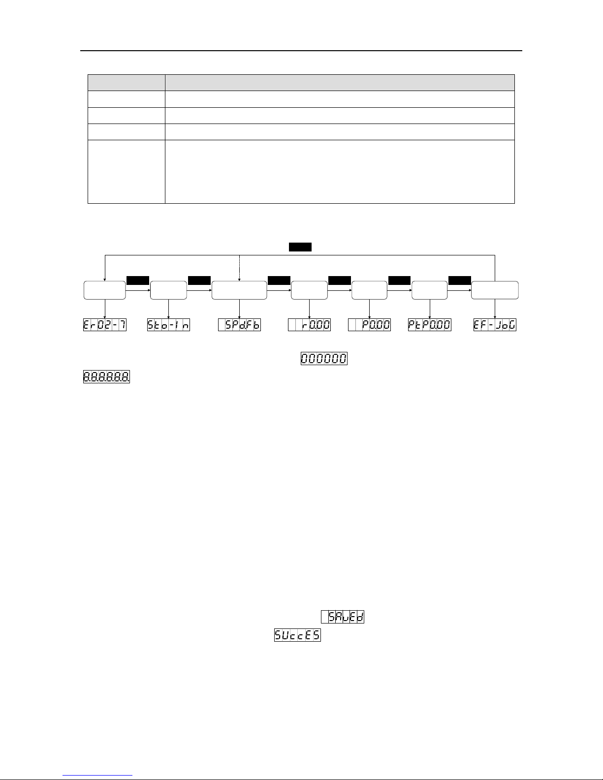
SV-DA200 series AC servo drive Running and operation
-84-
Button function table:
Key
Function
MODE
Used to switch between different modes or return to previous menu
UP
Used to select parameter upwards or increase value
DOWN
Used to select parameter downwards or decrease value
SET/ SHIFT
Press for a long time =SET (about 0.6 seconds)
Used to select parameter downwards or decrease value
Press for a short time =SHIFT:
When setting a parameter, it is used to select the position of the current digit
Operation flowchart:
Fault mode STO mode
Parameter
mode
Monitoring
mode
Auxiliary
function mode
MODE
PTP mode
Common
monitoring mode
MODEMODE MODE MODE
MODE
MODE
If the drive is power on, the screen will display for about 1 second, and then display
for about 1 second, after that, enter into the “General monitoring mode”.
1. Press MODE key to switch “General monitoring mode”→”Parameters mode”→”PTP mode”
→“ Auxiliary function mode”→“Fault mode”→“STO mode” as a cycle mode. If no fault or no STO
input, the fault mode and STO mode can be ignored.
2. If new fault occurs, it will switch to “Fault mode” by pressing MODE key. If no key is pressed in 20
seconds, it will switch to “Fault mode” automatically.
3. In “General monitoring mode”, UP/DOWN key can be used to switch monitoring parameters. The
name of parameters will display for 2.5 seconds, and then the current value will be displayed.
4. In parameters mode, SHIFT key can be used to switch the group number and UP/DOWN key can
be used to select the internal parameters number.
5. In the parameters setting mode, pressing SHIFT to make the flickering words move left and use
the UP/DOWN key to modify the setting value of the high bit.
6. After parameters setting, pressing SET key to save the parameters or execute the commands.
7. After parameters setting, the screen will display (for storage parameter and when
P0.17 is set to 0 [individual storage]) or (for non-storage parameter or P0.17 is set to
1 [batch storage]), and then return to the parameters mode automatically.

SV-DA200 series AC servo drive Running and operation
-85-
8. Setting of long parameters (corresponds to parameters with over 6 digits) in parameter area:
SHIFT
SHIFT
SHIFT
UP
DOWN
SET
UP DOWN
SHIFT UP
DOWN
SHIFT
SET
SHIFT
UP
DOWN
SET
MODE
5.2.2 State monitoring mode
After power on, the screen will enter into “General monitoring mode”, display the parameters name for
about 2.5 seconds and then display the current value. After pressing MODE key, UP/DOWN key can
be used to switch monitoring parameters. See chapter 10.3 Common monitoring parameter table for
details. The monitoring parameters displayed by default can be set via P0.15. If no operation is
carried out under interfaces other than parameter value display interface, it will return to the
monitoring parameter interface in 20 seconds.
Operation flowchart:
UP DOWN
DOWN
DOWN
UP
UP
MODE
Delay 2.5s or SET
MODE
Delay 2.5s or SET
MODE
Delay 2.5s or SET
5.2.3 Monitoring mode
MODE key can be used to switch into the monitoring mode. SHIFT key can be used to select the
group number of the monitoring parameters, UP/DOWN can be used to select the internal parameter
number and pressing for a long time, it can be used to select the parameter number quickly. After
finding the target, SET key can be used to view the current value and MODE can be used to return
the displaying interface. If no operation in R3 menu interface, it will return to the monitoring interface
in 20 seconds. If no operation in R0 and R1 menu interface, it will stay on the displaying interface.
Operation flowchart:

SV-DA200 series AC servo drive Running and operation
-86-
SHIFT
SHIFT
SHIFT
UP
DOWN
UP UP
SET MODE
DOWN DOWN
SET MODE
UPUPDOWN
DOWN
5.2.4 Parameter setting
MODE key can be used to switch into the parameters setting mode. SHIFT key can be used to select
the group number of the monitoring parameters, UP/DOWN can be used to select the internal
parameter number and pressing for a long time, it can be used to select the parameter number quickly.
After finding the target, SET key can be used to view the current value and SHIFT key to the
parameters setting. In the setting interface, UP/DOWN key can be used to set the value, SHIFT key
can be used to select the setting bit. After setting, press SET key to save the parameters. After
finishing, the screen will display (for storage parameters and P0.17 is set to 0) or
(for non-storage parameter or P0.17 is set to 1), and then return to the parameters mode
automatically.
Operation flowchart:
SHIFT
SHIFT
SHIFT
UP
DOWN
UP
DOWN
UP
SET MODE
SHIFT
SHIFT
UP
DOWN
SET
Delay 1s
DOWN
MODE
5.2.5 Auxiliary function instruction
5.2.5.1 Auxiliary function menu
Press MODE to the auxiliary mode and press UP/DOWN to select auxiliary functions, the auxiliary
function table is shown below:

SV-DA200 series AC servo drive Running and operation
-87-
Sign
Name
Jogging test
Restore the factory parameter
Program commissioning
Analog input 1 zero drift clear
Analog input 2 zero drift clear
Analog input 3 zero drift clear
Inertia identification
Absolute value encoder clear
Note: The auxiliary functions can be operated only when servo is disabled, otherwise users cannot
enter the auxiliary function menu.
5.2.5.2 Operation flowchart of trial jogging
Press MODE key to switch to the auxiliary function mode. Press UP/DOWN key to the
menu, and press SET key to the jogging interface. The interface will display the current speed of the
motor. Press UP key, the motor will rotate to the setting speed anticlockwise and stops when
releasing the key. Press DOWN key, the motor will rotate to the setting speed clockwise and stops
when releasing the key.
MODE
SET
UP press down
UP release
DOWN press down
DOWN release
5.2.5.3 Operation flowchart of restoring the factory parameter
Press MODE key to switch to the auxiliary function mode. Press UP/DOWN key to the
menu, and press SET key to the interface. The interface will display . Press SET key to
restore to the factory values, it will display , after finishing, it will display . The
operation flowcharts for restoring default values and clearing analog input 1 zero drift, analog input 2
zero drift and analog input 3 zero drift are the same.
MODESET
SET MODE

SV-DA200 series AC servo drive Running and operation
-88-
5.2.5.4 Operation flowchart of program commissioning
Press MODE key to the auxiliary function mode. Press UP/DOWN key to the menu, and
press SET key to the interface. The interface will display . In the interface of ,
SHIFT key can be used to switch between and , start and stop the
commissioning function. In the interface of , UP/DOWN key can be used to start the
program commissioning and has no relationship with P5.00. If the motor direction is counterclockwise,
it can be started by UP key. If the motor direction is clockwise, it can be started by DOWN key. After
starting, the interface will display the current speed.
SET
UP DOWN
MODE
MODE
MODE
SHIFTSHIFT
SHIFT
5.2.5.5 Operation flowchart of inertia identification
Press MODE key to the auxiliary function mode. Press UP/DOWN key to the menu, and
press SET key to the interface. The interface will display . Press SET key to start the
inertia identification. After finishing, the result will be displayed for about 3 seconds and
saved automatically. It will return to eh parameters after displaying for about 2 seconds.
SET
SET
Delay 3s
Delay 2s
MODE
MODE

SV-DA200 series AC servo drive Running and operation
-89-
5.2.5.6 Operation flowchart of absolute encoder clear
If the multi-turn encoders are used, the zeroing of mechanical system is needed after first power on.
Press MODE key to switch to the auxiliary function mode. Press UP/DOWN key to the
menu, and press SET key to the interface. The interface will display . Press SET key to
start the clearing, the interface will display , and after finishing, it will display ;
if the encoder model is not matched or the operation is failed, it will display .
Success Failure
SET
SET MODE MODE
MODE
MODE
5.2.6 Alarm display
When the servo drive runs abnormally, it will perform fault alarm and stop automatically. At this time
the panel will display the fault alarm warning sign. The format is ErXX-X, of which, XX is the master
code and X is the sub code.
Please refer to appendix 10.4 for the meanings of the alarm or warning identifiers.
5.2.7 Alarm clearing
For those faults that can be cleared online, if the fault condition is removed, fault alarm display can be
cleared by short connecting the digital input terminal configured as fault clearing function
(P3.00–P3.09 configured as 0x004 or 0x104) with COM-. If the servo still has enabling command
input, the drive will not be able to clear the fault automatically.
For the fault alarms which cannot be cleared online, it can be cleared after repower on.

SV-DA200 series AC servo drive Function codes
-90-
6 Function codes
P-position mode; S-speed mode; T-torque mode.
The definition of direction: From the angle of facing motor shaft, the counterclockwise direction is
forward (CCW for short); clockwise (CW) is reverse; in terms of speed and torque reference value,
positive value means position direction and negative value means negative direction.
The function codes with the superscript of “1” indicate that these parameters can be valid only when
the system is reset and restarted or repowered after disconnection.
The function codes with the superscript of “2” indicate that these parameters are valid when the servo
drive stops. The modification during operation is invalid.
The function codes with the superscript of “*” indicate that these parameters are not saved after
power off.
Modbus communication address is decimal, the address of PROFIBUS-DP is the same with Modbus;
CANopen communication address is hex and the length of 16-bit is the primary code and the length of
8-bit is the sub-code.
6.1 Basic control (P0 group parameters)
6.1.1 Basic setting
P0.001
Motor model
Setting range
Default
Unit
Available mode
0–9999999
0
- P S
T
This parameter is set to 0 by default. Users must set according to motor nameplate.
If the motor model is 0, and the motor is standard communication-type encoder motor, the drive
will read the motor parameters automatically.
For example, the nameplate of 400W motor is shown below.
INPUT: AC 3PH 220V 2.8A
OUTPUT(RATED): 400W 3000r/min 1.3N·m
IP65 S1 CLASS F NO.3010004(236)
MODEL: SV-ML06-0R4G-2-4A0-3000
Of which, No.: 3010004 is the set value of the parameter.
Note: Improper parameter value will result in abnormal operation of servo system, or even lead
to serious drive or motor faults. Double check whether this parameter matches with the motor
before the initial power up.
P0.001
Data size
32bit
Data format
DEC
Modbus address
1000, 1001
CANopen address
0x2000, 0x00

SV-DA200 series AC servo drive Function codes
-91-
P0.011
Encoder type
Setting range
Default
Unit
Available mode
1–12
4*1
- P S
T
Generally, the system will set this parameter automatically after P0.00 is set correctly. In cases
where encoder disconnection fault is reported during power up when motor is connected
correctly, please check whether the drive supports motor encoder type, refer to chapter 1.1.3.
The naming of servo motor contains encoder type, refer to chapter 1.2.2.
Relation between encoder type and P0.01 setting value:
Motor nameplate
Encoder type*2
Setting value
Meaning
1
1
2500-PPR standard incremental
3
3
17-bit single-turn absolute value
4
[4]
17-bit multi-turn absolute value *3
7
8
Rotary transformer
9
10
23-bit multi-turn absolute value *3
-
Other value
Reserved
*1 Different motors correspond to different types of encoders.
*2 Refer to chapter 1.2.2 .
*3 When the multi-turn encoders are used, it is necessary to change the battery when the drive is
power on to prevent losing absolute position. The standard battery is 2000mAh and the
replacement cycle is 1.5–2 years.
P0.011
Data size
16bit
Data format
DEC
Modbus address
1002, 1003
CANopen address
0x2001, 0x00
P0.02
1
Forward rotation of motor *1
Setting range
Default
Unit
Available mode
0–1
0
- P S
T
Set the forward rotation of motor:
Setting value
Definition
[0]
Anticlockwise is forward rotation
1
Clockwise is forward rotation
*1 Definition of forward rotation of motor. The view angle faces shaft output direction of motor.
P0.02
1
Data size
16bit
Data format
DEC
Modbus address
1004, 1005
CANopen address
0x2002, 0x00
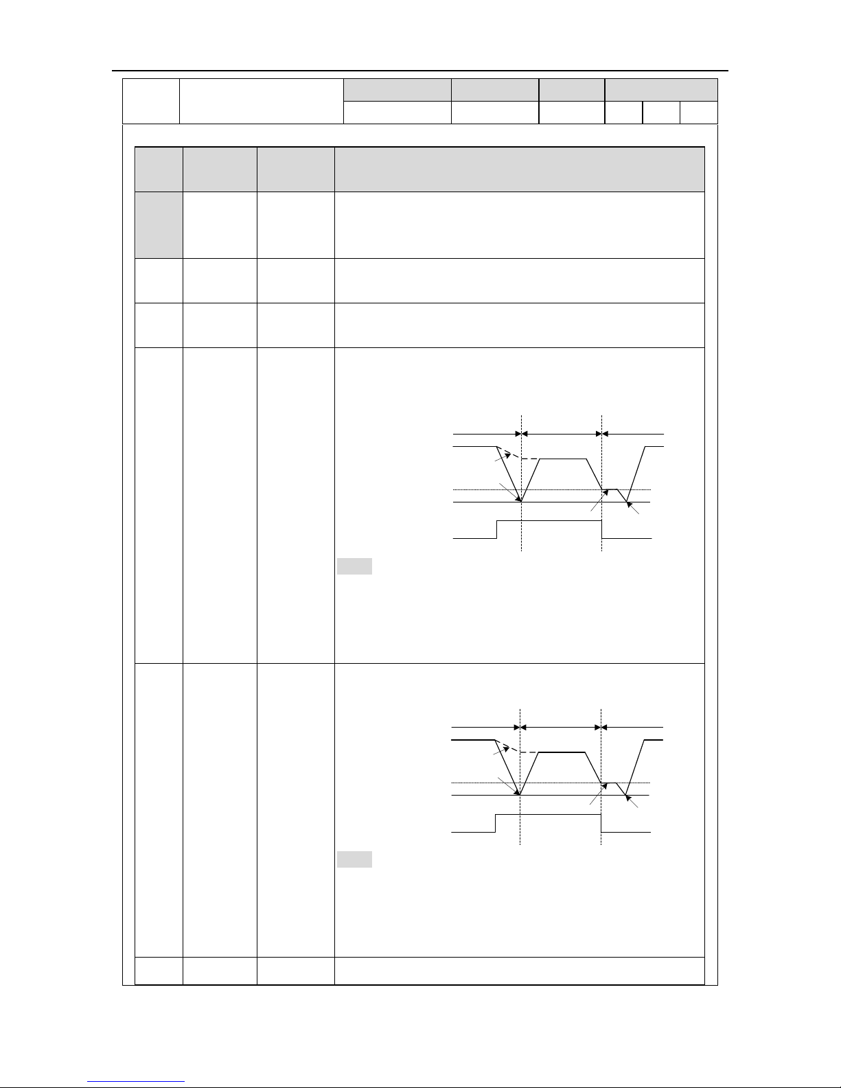
SV-DA200 series AC servo drive Function codes
-92-
P0.031
Control mode selection
Setting range
Default
Unit
Available mode
0–9
0
- P S
T
This parameter can be used to set the operating mode of the system:
Setting
value
1st working
mode
2nd working
mode
Instruction
[0] P /
Position mode: Control the angular displacement of servo
motor via internal/external position command, thus
achieving controlling over mechanical motion displacement.
1 S /
Speed mode: Control the rotation speed of the servo motor
with the internal or external speed command
2 T /
Torque mode: Control the torque of the servo motor with the
internal or external torque command.
3 P S
Position/speed mode switching: The position mode and
speed mode can be switched with the control mode
switching terminal.
ON
OFF
(P0.90)
P0.92 = 1
P0.92 = 0
(P0.91)
Speed modePosition mode Position mode
Motor
speed
Mode switching
signal (MCH)
Note: For switching from position mode to speed mode,
there are two kinds of switching methods which can be
selected via P0.92; When switching from speed mode to
position mode, the motor will stop at the reference position
of P0.91 before switching to position mode.
4 P T
Position/torque mode: The position mode and torque mode
can be switched with the control mode switching terminal
ON
OFF
(P0.90)
P0.92 = 1
P0.92 = 0
(P0.91)
Torque modePosition mode Position mode
Motor
speed
Mode switching
signal (MCH)
Note: For switching from position mode to torque mode,
there are two kinds of switching methods which can be
selected via P0.92; When switching from torque mode to
position mode, the motor will stop at the reference position
of P0.91 before switching to position mode.
5 S T
Speed/torque mode: The speed mode and torque mode can

SV-DA200 series AC servo drive Function codes
-93-
be switched with control mode switching terminal
ON
OFF
Torque command
Load torque
Torque modeSpeed mode Speed mode
Motor speed
Mode switching
signal (MCH)
Note: The switching mode is not limited by actual operation.
6 / /
Reserved
7
CANopen
/
CANopen mode (CANopen type servo support)
8
EtherCAT
/
EtherCAT mode (EtherCAT type servo support)
9
MotionNet
/
MotionNet mode (MotionNet type servo support)
Remark: Set P0.03 and P3.00–P3.09 will switch automatically according to the selected control mode.
Note:0:OFF (internal optical coupler corresponding to the input is not conducted);
1:ON (internal optical coupler corresponding to the input is conducted).
P0.031
Data size
16bit
Data format
DEC
Modbus address
1006, 1007
CANopen address
0x2003, 0x00
P0.04*
Internal enabling
command
Setting range
Default
Unit
Available mode
0–1
0
- P S
T
This parameter is used to control the operation state of the servo drive.
The relation between internal enable instruction and external terminal enable instruction is shown
below:
Setting value
External terminal command state
Working state of servo drive
0
0 (internal optical coupler which corresponds
to the input is not conducted)
Stand-by (OFF)
0
1(internal optical coupler which corresponds
to the input is conducted)
Enabling running (ON)
1
0 (internal optical coupler which corresponds
to the input is not conducted)
Enabling running (ON)
1
1 (internal optical coupler which corresponds
to the input is conducted)
Enabling running (ON)
Note:
1. When P0.04 is 1 and the external terminal command converts from 1 to 0, the servo drive will
be disabled, namely P0.04 will change to 0 automatically.
2. When this parameter is operated via the LED panel, it can only be switched between 0 and 1
via SET key and UP/DOWN key is invalid under the setup interface of this parameter.
P0.04*
Data size
16bit
Data format
DEC
Modbus address
1008, 1009
CANopen address
0x2004, 0x00

SV-DA200 series AC servo drive Function codes
-94-
P0.05
JOG speed
Setting range
Default
Unit
Available mode
0–1000
200
r/min
P S T
This parameter can be used to set the jog speed. For jogging, please refer to chapter 5.2.5.2
During jogging, the ACC/DEC time parameters (P0.54, P0.56, P0.55, and P0.57) are active. The
motor will accelerate, decelerate, start and stop according to the settings.
P0.05
Data size
16bit
Data format
DEC
Modbus address
1010, 1011
CANopen address
0x2005, 0x00
P0.061
Numerator of frequency
division output coefficient
Setting range
Default
Unit
Available mode
0–(231-1)
10000
- P S
T
P0.071
Denominator of frequency
division output coefficient
Setting range
Default
Unit
Available mode
1–(231-1)
131072
- P S
T
By setting the numerator and denominator of the frequency division output, the signal of the
encoder can be frequency divided by any integer or decimal fraction and then outputted through
the encoder’s pulse output signal terminals(OA+, OA-, OB+ and OB- pin “44”“43”“41” and “42”)
Number of drive output pulse=
P0.06
P0.07
X encoder resolution
Note:
1. In the position control mode, if the encoder output signal of the preceding stage servo motor is
used as the position pulse command input of the succeeding stage servo drive, i.e. as start/stop
type master-slave follow-up, in order to ensure high positioning accuracy of the succeeding stage
servo drive, the frequency division coefficient must be 1:1. Otherwise the accuracy of
master-slave position follow-up will be affected in this case.
2. In factory setting, P0.07 is 131072, P0.06 is 10000, which means the output terminal of the
encoder will output 10000 pulse signal when the motor rotates a circle. If P0.06 is 5000, the
output terminal of the encoder will output 5000 pulse signal.
P0.061
Data size
32bit
Data format
DEC
Modbus address
1012, 1013
CANopen address
0x2006, 0x00
P0.071
Data size
32bit
Data format
DEC
Modbus address
1014, 1015
CANopen address
0x2007, 0x00
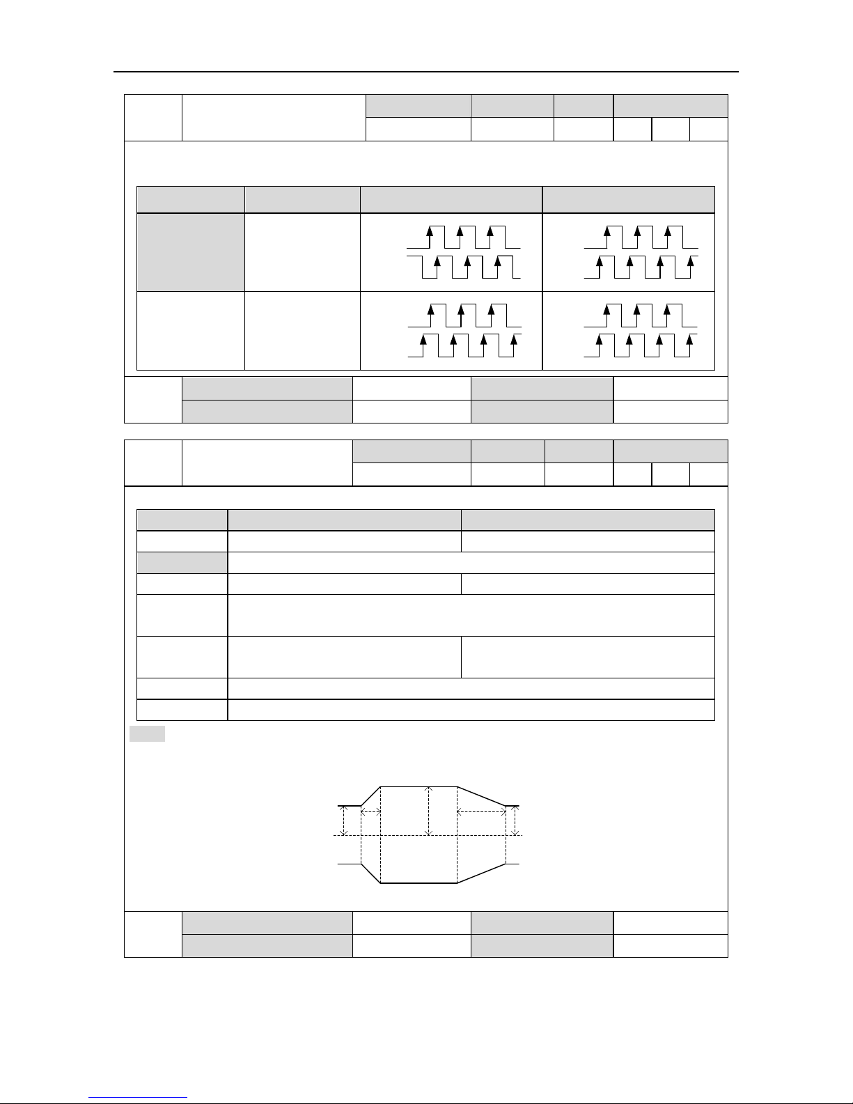
SV-DA200 series AC servo drive Function codes
-95-
P0.081
Reverse of frequency
division output
Setting range
Default
Unit
Available mode
0–1
0
- P S
T
The reverse of B phase can be carried out through this parameter and the phase relation
between A phase and B phase can be changed:
Setting value
Logic of B phase
CCW
CW
[0]
Non-reverse
A phase
B phase
A phase
B phase
1
Reverse
A phase
B phase
A phase
B phase
P0.081
Data size
16bit
Data format
DEC
Modbus address
1016, 1017
CANopen address
0x2008, 0x00
P0.09
Torque limit mode setting
Setting range
Default
Unit
Available mode
0–6
1
- P S
This parameter is used to set the torque limit mode.
Setting value
Forward direction
Reverse direction
0
Torque limit (analog input 0V–10V)
Torque limit (analog input -10V to +10V)
[1]
Max. torque limit 1 (P0.10)
2
Max. torque limit 1(P0.10)
Max. torque limit 2(P0.11)
3
TLC OFF →Max. torque limit 1(P0.10)
TLC ON → Max. torque limit 2(P0.11)
4
Forward torque limit
(analog input 0V–10V)
Negative torque limit
(analog input 0V–10V)
5
Forward torque limit (analog input 0V–10V)
6
Torque command (analog input 0V–10V)
Note: If P0.09 is 3, the torque switching will not become effective instantly and will be limited by
P4.51 and P4.52, the detailed information is shown in the figure below:
P0.10
P0.11
0
torque
Ta Tb
P0.10
Ta[ms]=|P0.11[%]-P0.10[%]|×P4.51[ms/100%]/100
Tb[ms]=|P0.10[%]-P0.11[%]|×P4.52[ms/100%]/100
P0.09
Data size
16bit
Data format
DEC
Modbus address
1018, 1019
CANopen address
0x2009, 0x00

SV-DA200 series AC servo drive Function codes
-96-
P0.10
Max. torque limit 1
Setting range
Default
Unit
Available mode
0.0–500.0
300.0
% P S
T
P0.11
Max. torque limit 2
Setting range
Default
Unit
Available mode
0.0–500.0
300.0
% P S
These parameters can be used to set the maximum torque of the servo motor output. Taking the
rated torque of the servo motor as 100%, the setting is the percentage of the rated torque of the
servo motor. If the absolute value of the torque command is larger than the value of this
parameter, then the actual output torque will be limited by the parameter.
Note:
1. These parameters are used with P0.09;
2. In torque mode, the limit value is determined by P0.10.
P0.10
Data size
16bit
Data format
DEC
Modbus address
1020, 1021
CANopen address
0x200A, 0x00
P0.11
Data size
16bit
Data format
DEC
Modbus address
1022, 1023
CANopen address
0x200B, 0x00
P0.131
Power of the external
braking resistor
Setting range
Default
Unit
Available mode
0–5000
200
W
P S T
P0.141
Resistance of the external
braking resistor
Setting range
Default
Unit
Available mode
1–1000
60
Ω
P S T
When an external braking resistor is connected, this group of parameters should be set with the
values equal to the resistance and power of the external braking resistor.
Note: Braking overload detection should be used in combination with P4.34, when P4.34 is set to
2, braking overload uses external braking resistor parameter to perform fault detection; please
set this group of parameters correctly. If the value of this group of parameters does not match
with external braking resistor, braking overload fault (Er07-0) may be reported by mistake or
braking resistor may be burnt down. The regenerative braking overload protection time of
external braking resistor is in proportion to these two parameters and is in reverse proportion to
the braking rate during actual operation.
When P4.34 is set to other values, these two parameters are invalid.
P0.131
Data size
16bit
Data format
DEC
Modbus address
1026, 1027
CANopen address
0x200D, 0x00
P0.141
Data size
16bit
Data format
DEC
Modbus address
1028, 1029
CANopen address
0x200E, 0x00
 Loading...