


iMars MG Series
Grid-tied Solar Inver ter

Preface
Thank you for purchasing iMars MG series grid-tied solar inverters.
iMars MG series grid-tied solar inverters is mainly used in sol ar photovoltaic grid system. As a
non-isolation and high-efficiency string photovoltaic grid-tied inverter, it transfers DC energy
generated by solar modules to sinusoidal AC energy and feedback to public grid. The energy has
the same frequency and phase with the utility grid.
The manual is intended to provide detailed information of installation, application, trouble shooting,
precautions and maintenance of iMars MG series grid-tied solar inverters. Please read this manual
carefully and follow all safety prec autions seriously before any moving, installation, operation and
maintenance to ensure correct use and high performance of operation on the inverter.
Configured monitoring and design software for iMars MG series grid-tied sol ar inverters are also
provided. Go to www.invt-solar.com and download the software installation package and use
instructions.
The inverter complies with local regulations and laws on grid feeding.
The manual needs to be kept well and be available at all times.
All rights reserved. The contents in this document are subject to change without notice.
There may be data deviation because of product improving. Detailed information is in accordant
with the final product.
- 1 -

INVT iMars MG series grid-tied solar inverters Content
Contents
Preface ............................................................................................................................................ 1
Contents ......................................................................................................................................... 2
1 Safety precautions ...................................................................................................................... 5
1.1 Icons ..................................................................................................................................... 6
1.2 Safety guidelines................................................................................................................... 6
1.2.1 Delivery and installation ................................................................................................ 7
1.2.2 Grid-tied operation ........................................................................................................ 8
1.2.3 Maintenance and inspection ......................................................................................... 8
1.2.4 What to do after scrapping ............................................................................................ 8
2 Product overview ........................................................................................................................ 9
2.1 Solar grid-tied power generation system ............................................................................ 10
2.2 Products appearance .......................................................................................................... 11
2.2.1 Single-phase inverters ................................................................................................ 11
2.3 Name plates ........................................................................................................................ 11
2.3.1 Name plate on the package ........................................................................................ 12
2.3.2 Name plate on the inverter.......................................................................................... 12
2.3.3 Models ........................................................................................................................ 13
2.4 Technical parameters ......................................................................................................... 14
2.5 Dimensions and weight ....................................................................................................... 16
3 Installation ................................................................................................................................. 18
3.1 Unpacking inspection .......................................................................................................... 19
3.2 Before installation ............................................................................................................... 20
3.2.1 Installation tools .......................................................................................................... 20
3.2.2 Installation place ......................................................................................................... 20
3.2.3 Connection cables ...................................................................................................... 21
3.2.4 Miniature circuit breakers ............................................................................................ 22
- 2 -

INVT iMars MG series grid-tied solar inverters Content
3.3 Mechanical installation ........................................................................................................ 23
3.3.1 Installation of single-phase inverter ............................................................................ 23
3.4 Electrical installation ........................................................................................................... 25
3.4.1 Connection of solar modules ...................................................................................... 26
3.4.2 AC connection of single-phase inverter ...................................................................... 27
4 Operation ................................................................................................................................... 28
4.1 Inspection before operation ................................................................................................ 29
4.2 Grid-tied operation .............................................................................................................. 29
4.3 Stopping .............................................................................................................................. 30
4.4 Daily maintenance .............................................................................................................. 30
4.4.1 Regular maintenance .................................................................................................. 30
4.4.2 Maintenance guide...................................................................................................... 31
5 Display panel ............................................................................................................................. 32
5.1 LED indicators..................................................................................................................... 33
5.2 Operation panel .................................................................................................................. 34
5.3 LCD screen ......................................................................................................................... 35
5.4 Functions operation ............................................................................................................ 36
5.4.1 Monitoring parameters ................................................................................................ 36
5.4.2 History ......................................................................................................................... 36
5.4.3 Statistics ...................................................................................................................... 37
5.4.4 Parameter settings ...................................................................................................... 37
5.4.5 System Information ..................................................................................................... 45
5.4.6 Faults .......................................................................................................................... 45
5.4.7 Inverter control ............................................................................................................ 45
5.4.8 Mode settings.............................................................................................................. 46
5.5 Grid Certification Choice ..................................................................................................... 47
6 Monitoring communication ...................................................................................................... 50
6.1 Standard communication .................................................................................................... 51
- 3 -

INVT iMars MG series grid-tied solar inverters Content
6.2 Optional communication ..................................................................................................... 52
6.2.1 WiFi200 converter ....................................................................................................... 53
6.2.1.1 WiFi200 Product Introduction .................................................................................. 53
6.2.1.2 Monitoring solutions ................................................................................................. 54
6.2.1.3 Installation and commissioning ................................................................................ 56
7 Troubleshooting ....................................................................................................................... 64
8 Contact us ................................................................................................................................. 67
- 4 -

INVT iMars MG series grid-tied solar inverters Safety precautions
1 Safety precautions
This chapter describes various warning symbols in the operation manual of iMars series inverters.
It is intended to provide the installers and the users with all safety information about installation,
operation, and use of the inverter.
- 5 -
INVT iMars MG series grid-tied solar inverters Safety precautions
requirements
ed, contact the shipping
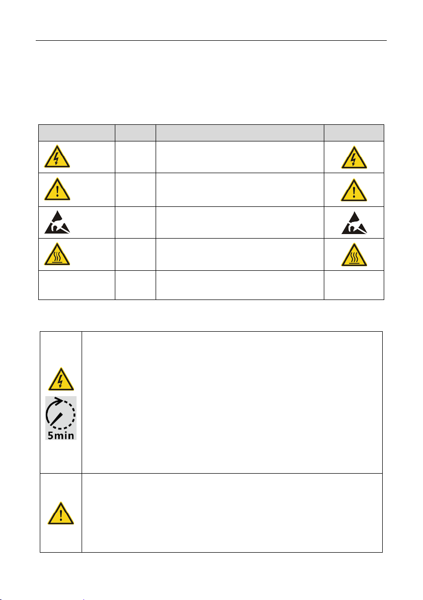
1.1 Icons
This manual provides relevant information with icons to highlight the physical and property safety
of the user to avoid device damage and physical injury.
The icons used in this manual are listed below:
Icons Name Instruction Abbreviation
Danger
Warning
Do not
Hot sides
Note Note
Danger
Warning
Do not
Hot
sides
Serious physical injury or even death may
occur if not follow the relative requirements
Physical injury or damage to the devices
may occur if not follow the relative
Damage may occur if not follow the relative
requirements
Sides of the device may become hot. Do not
touch.
Physical hurt may occur if not follow the
relative requirements
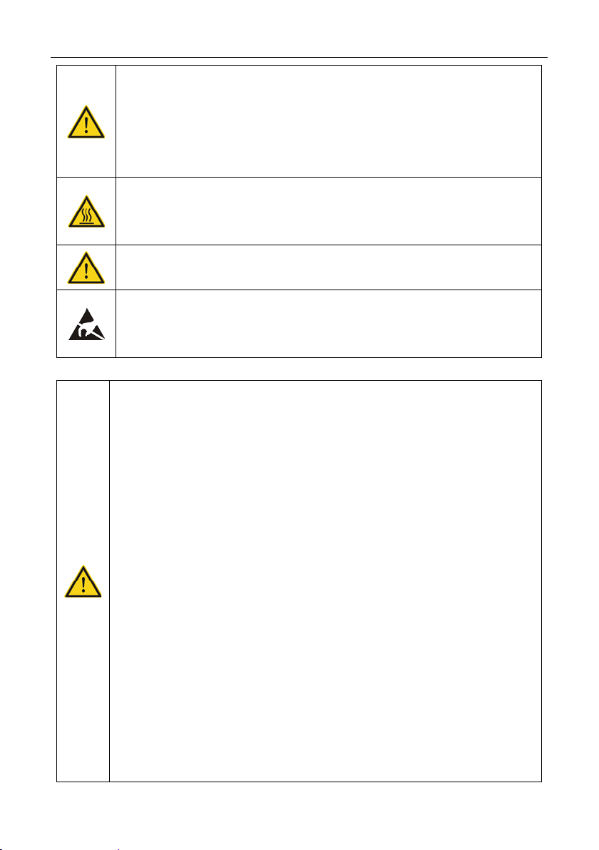
1.2 Safety guidelines
The first thing after receiving is to check for any visible damage to the package
or to the inverter. If there is something suspect
company and local dealer before installing.
Only qualified electricians are allowed to operate on the inverter.
Do not carr y out any wiring and inspection or changing components when the
power supply is applied. Hazardous voltages may still be present in the inverter
even if the AC and DC main switches are switched off. Wait at least 5 minutes
after switching off the inverter. This ensures that the capacitors are electrically
discharged.
This product can cause a d c current in the external protective earth conductor.
Where a residual current-operated protective (RCD) or monitoring (RCM)
device is strongly recommend to used for protection in a case of direct or
indirect contact, only an RCD or RCM of Type B is allowed on the supply side
of this product;
Note
- 6 -
INVT iMars MG series grid-tied solar inverters Safety precautions
Ensure that there is no electromagnetic interference from other electrical and
electronic equipments on the installation site.
Do not refit the inverter unauthorized.
All the electric installation needs to be compliance with the natio nal or local
laws and standards.
The temperature of individual parts or the enc losure of the inverter–especially
the heat sink may become hot in normal operation. There is a danger of
burning. Do not touch.
Must be grounded before operation.
Do not open the cover of inverters unauthorizedly. The electrical parts and
components inside the inverter are electrostatic. Take measurements to avoid
electrostatic discharge during relevant operation.
1.2.1 Delivery and installation
Keep the package and unit complete, dry and clean during storage and delivery.
Please remove and install the inverter with two o r more people, be cause of the
inverter is heavy.
Remove and install the inverter with appropriate tools to ensure safe and normal
operation and avoid physical injur y or death. The people also need mechanical
protective measures, such as protective shoes and work clothes.
Only qualified electricians are allowed to install the inverter.
Do not put and install the inverter on or close to combustible materials.
Keep the installation site away from children and other public places.
Remove the metal jewelry such as ring and bracelet before installation and
electrical connection to avoid electric shock.
Do cover solar modules with light-tight materials. Exposed to sunlight, solar
modules will output dangerous voltage.
The inverter input voltage does not exceed the maximum input voltage;
otherwise inverter damage may occur.
The positive and negative pole of solar modules can not be grounded, otherwise
irrecoverable damage may occur.
Ensure the proper grounding of the inverter, otherwise, improper connection or
- 7 -

INVT iMars MG series grid-tied solar inverters Safety precautions
under the
o not use parts and components not provided by our company during
no grounding may cause stop of the inverter.
Ensure reliable installation and electrical connection.
When the photovoltaic generator cells are exposed to light (even if it is dim), the
generator supplies DC voltage to the inverter.
modules.
1.2.2 Grid-tied operation
Only qualified electricians are allowed to operate the inverter
permission of local power departments.
Ensure reliable installation and electrical connection before operation.
Do not open the cover of inverter during operation or voltage is present.
1.2.3 Maintenance and inspection
Only qualified electricians are allowed to perform the maintenanc e, inspection,
and components replacement of the inverter.
Contact with the local dealer or supplier for maintenance.
Firstly disconnect all power supplies of the grid to the inverter before any
maintenance, and then disconnect the breakers and wait fo r at least 5 minutes
until the inverter is discharged before maintenance.
Please follow electrostatic protection norms and take correct protective
measures because of the electrostatic sensitive circuits and devices in the
inverter.
D
maintenance.。
Restart the inverter after settling the fault and problem which may affect the
safety and performance of the inverter.
Do not get close to or touch any metal conductive part of the gri d or inverter,
otherwise electric shock, physical injury or death and fire may occur. Please do
not ignore the warning icons and instructions with “electric shock”.
1.2.4 What to do after scrapping
Deal with the inverter as industrial effluent.
- 8 -

INVT iMars MG series grid-tied solar inverters Product overview
2 Product overview
This chapter mainly describes the appearance, packaging accessories, name plate, technic al
parameters and other information of iMars MG series grid-tied solar inverters.
- 9 -
INVT iMars MG series grid-tied solar inverters Product overview
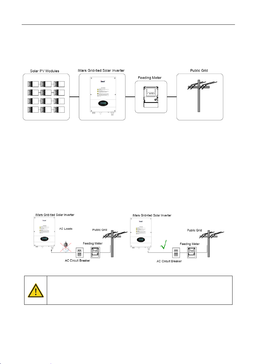
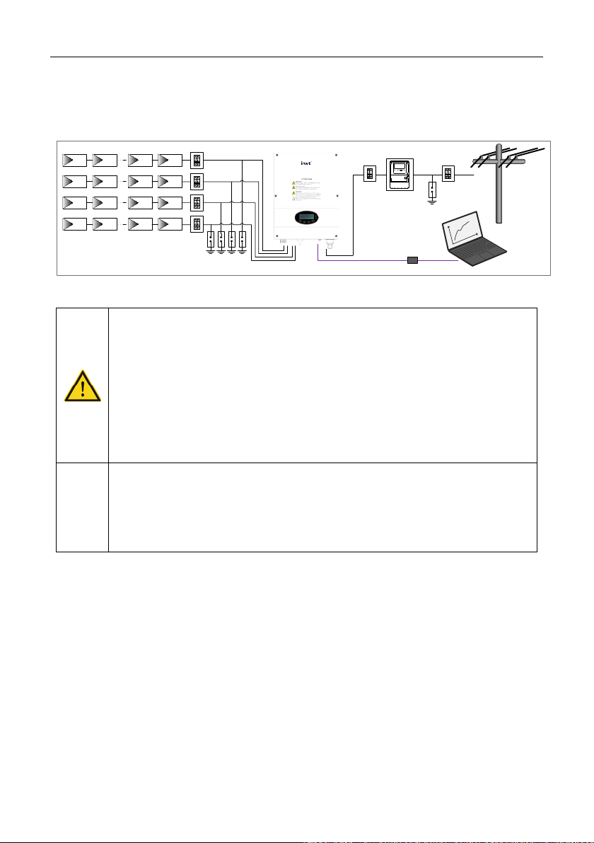
2.1 Solar grid-tied power generation system
The photovoltaic grid-tied power generation system consists of solar modules, grid-tied inverter,
metering devices and public grid.
Figure 2.1 Application of iMars MG series grid-tied solar inverters
Grid-tied solar inverter is the core of photovoltaic power generation system. The sol ar energy can
be converted into DC electric energy through solar modules and then be changed into sinusoidal
AC energy which has the same frequency and phase with the public grid by grid-tied solar
inverters, and then be fed to the grid.
iMars MG series grid-tied solar inverters are only applied in solar grid-tied power generation
system and its DC input are only composed of crystalline silicon solar modules whose negative
and positive poles are not grounded. Do not connect an y AC loads between the inverter and
breakers which is shown as the figure below:
Figure 2.2 Connection of inverters and AC breakers
The recommended solar modules need to comply with IEC61730 Class A rating.
iMars MG series grid-tied solar inverters are only for crystalline silicon solar
modules.
- 10 -

INVT iMars MG series grid-tied solar inverters Product overview
1
2
3
4
5
6
7
8
9
No.
Name
Instruction
1
Cover 2
Operational panel
LED indicators
5
AC terminal
For the connection of AC output
6
Communication port
RS485 and EXT communication port
7
Cooling chamber
2.2 Products appearance
2.2.1 Single-phase inverters
Figure 2.3 Products appearance of single-phase inverter
Table 2-1 Parts instruction of single-phase inverter
3 DC switch On –off of the DC input
4 DC input port For the connection of solar modules
8 Radiator
9 Name plate
2.3 Name plates
After receiving, please check the information of name plates are the ordered one. If not, please
contact with the supplier as soon as possible.
For rated parameters and safety precautions
of the inverter
- 11 -

INVT iMars MG series grid-tied solar inverters Product overview
2.3.1 Name plate on the package
The information on the name plate of the package includes the inverter model, certification
logo,,protective degree, gross weight, environmental logo, and brand information and so on.
Figure 2.4
Name plate on the package
2.3.2 Name plate on the inverter
The information on the name plate of the inverter includes the brand information, product name,
product model, DC input parameters, AC output parameters, operation temp erature, protective
degree, grid certificate standard, certification logo, environmental logo, and serial No. of the
product and so on.
- 12 -

INVT iMars MG series grid-tied solar inverters Product overview
Figure 2.5
Name plate on the inverter
2.3.3 Models
Table 2-2 Models of iMars grid-tied solar inverter
Product name Model Rated output power
Single-phase (L, N, PE)
Single-phase grid-tied solar inverter iMars MG750TL 750
Single-phase grid-tied solar inverter iMars MG1KTL 1000
Single-phase grid-tied solar inverter iMars MG1K5TL 1500
Single-phase grid-tied solar inverter IMars MG2KTL 2000
Single-phase grid-tied solar inverter iMars MG3KTL 3000
Single-phase grid-tied solar inverter iMars MG4KTL 4000
Single-phase grid-tied solar inverter iMars MG4K6TL 4600
Single-phase grid-tied solar inverter iMars MG5KTL 5000
Single-phase grid-tied solar inverter iMars MG3KTL-2M 3000
Single-phase grid-tied solar inverter iMars MG4KTL-2M 4000
Single-phase grid-tied solar inverter iMars MG4K6TL-2M 4600
Single-phase grid-tied solar inverter iMars MG5KTL-2M 5000
Note: Refer to the product specifications in section 2.3 for detailed information.
- 13 -
INVT iMars MG series grid-tied solar inverters Product overview
Single-phase
MG750TL
MG1K1TL
MG1K5TL
MG2KTL
MG3KTL
MG4KTL
MG4K6TL
MG5KTL
MG3KTL
MG4KTL-2M
MG4K6TL-2M
MG5KTL-2M
Starting voltage
(V)
MPPT
voltage(V)
Operation
voltage (V)
MPPT/strings
per MPPT
Max. DC power
(W)
Max. input
current (A)
Max. inverter
array
DC switch
Optional
Optional
Null
Max.
(W)
Nominal
frequency
Voltage(V)
range
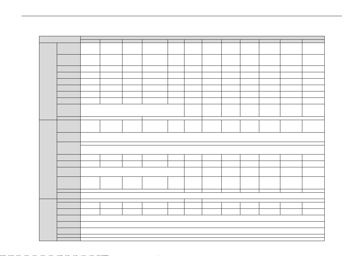
180~270Vac、50Hz(47~51.5Hz) / 60Hz(57~61.5Hz)
Max. AC
current (A)
Current
(inrush)
5 A
(3
ms)
6.5 A
(3
ms)
9.5 A
(3
ms)
18A
(3 ms)
Maximum
current
Maximum
protection
Power factor
≥0,99 (rated load)
Harmonic
distortion
Cooling
Natural cooling Natural cooling
Maximum
efficiency
97.40%
97.50%
97.60%
97.30%
97.40%
97.40%
European
efficiency
96.50%
96.50%
96.50%
96.40%
96.50%
96.50%
MPPT
efficiency
Protection
degree
Power
consumption
Isolation mode
Transformerless
Operation
(-25 ℃~ +60℃) ,derate after 45 ℃
2.4 Technical parameters
Table 2-3 Technical parameters of single-phase inverter
Model
Vmax PV 400 450 450 450 500 600 600 600 600 600 600 600
Recommended
DC side
Max. DC
voltage (V)
backfeed
current to the
400 450 450 450 500 550 550 550 550 550 550 550
60 80 80 120 120 120 120 120 120 120 120 120
50-400 60-400 80-410 100-410 120-450 120-550 120-550 120-550 120-550 120-550 120-550 120-550
180-450 180-450 200-450 200-500 200-500 200-500 200-500 250-500 270-500 180-500 190-500 200-500
1/1 1/1 1/1 1/1 1/2 2/2 1/2 1/2 1/2 2/1 2/1 2/1
900 1200 1700 2200 3300 4000 4600 5000 3000 4000 4600 5000
8x1 9x1 10x1 12×2 15×2 18×2 18×1 18×1 18×1 14×2 15×2 16×2
46 Apeak impulse (0,38 ms duration)
Continuous
output power
voltage /
frequency(Hz)
AC side
output fault
output
overcurrent
System
range /
750 1100 1500 2000 3000 4000 4600 5000 3000 4000 4600 5000
Single phase, 230 Vac, 50 Hz
VDE0126& AR-N4105、AS4777.2/AS4777.3、CQC、G83-2、G59-3、C10/11、TF3.2.1、PEA
99.9%
IP65
< 1W
20 14 16① 18.3 20
3.6 4.5 6.5 9 13 16 18.3
peak
40 Apeak impulse (19,5 ms duration)
4 A 4.8 A 7.1 A 10 A 14 A
96.90% 97.20% 97.30% 97.40% 97.60% 97.60%
96.00% 96.10% 96.30% 96.50% 96.50% 96.50%
peak
peak
13 A
(3 ms)
peak
peak
< 3% (rated power)
- 14 -

INVT iMars MG series grid-tied solar inverters Product overview
Single-phase
MG750TL
MG1K1TL
MG1K5TL
MG2KTL
MG3KTL
MG4KTL
MG4K6TL
MG5KTL
MG3KTL
MG4KTL-2M
MG4K6TL-2M
MG5KTL-2M
temperature
Relative
humidity
Max.
altitude(m)
Overvoltage
category:
Displaying
LED/ LCD, backlit display
Systerm
language
Communication
RS485 (standard); handheld keypad; WiFi (optional)
DC terminal
SUNCLIX water-proof terminal
≤25
Installation
mode
Protection
Input overvoltage protection, input overcurrent protection, DC isolation monitoring, DC monitoring, grounding fault current monitoring, grid monitoring, island protection, short circuit protection, overheating prot ect i on
Remarks
①
G83: the maximum output current is 16A; others: the maximum output current is 18A.
Model
4% ~ 100%., no Condensation
<2000 (derate if the altitude>2000)
II(DC side), III(AC side)
English, Chinese, German, Dutch
Noise dB(A)
≤25 ≤55
Wall installation
- 15 -

INVT iMars MG series grid-tied solar inverters Product overview
(mm)
(mm)
(mm)
(kg)
MG4KTL /MG5KTL
365
360
160
15
2.5 Dimensions and weight
Figure 2.6 Inverter dimensions
Table 2-4 Inverter di mens ion and net weight
Model
MG750TL/MG1KTL / MG1K5TL /
MG2KTL /MG3KTL
MG3KTL-2M/ MG4K6TL/
MG4KTL-2M/MG4K6TL-2M/
MG5KTL-2M
H
280 300 138 9.5
420 360 160 17
W
D
Net weight
- 16 -

INVT iMars MG series grid-tied solar inverters Product overview
W
H
D
MG2KTL/MG3KTL
MG5KTL-2M
Figure 2.7 Paper packages dimension
Table 2-5 Packages dimension and gross weight
Model
MG750TL/MG1KTL/MG1K5TL /
H
(mm) W (mm) D (mm)
411 418 249 12 Paper
Gross
weight (kg)
Packaging
Material
MG4KTL/MG4K6TL 518 480 284 16.5 Paper
MG3KTL-2M/ MG4K6TL/
MG4KTL-2M/MG4K6TL-2M/
573 480 284 18.5 Paper
- 17 -

INVT iMars MG series grid-tied solar inverters Installation
3 Installation
This chapter describes how to install the inverter and connect it to the grid-tied solar system
(including the connection between solar modules, public grid and inverter).
Read this chapter carefully and ensure all installation requirements are met before installation.
Only qualified electricians are allowed to install the inverter.
- 18 -

INVT iMars MG series grid-tied solar inverters Installation
MG4K6TL-2M/MG5KTL-2M inverter
3.1 Unpacking inspection
Inspect the information of the order and the name plate to ensure the product are the ordered one
and no damage to the package. If any problem, contact the supplier as soon as possible.
Put the inverter into the package if not used and protect it from humidity and dust.
Check as following after unpacking:
(1) Ensure no damage to the inverter unit;
(2) Ensure the operation manual, port and installation accessories in the package;
(3) Ensure no damage or loss to the items in the package;
(4) Ensure the information of the order are the same as that of the name plate;
(5) The delivery list of single-phase inverter is different from that of three-phase inverter.
Below are the detailed lists:
Packing list of single-phase inverter:
Figure 3.1 Packing list of single-phase inverter
Table 3-1 Detailed delivery list of single-phase inverter
No. Name Quantity
MG750TL/MG1KTL/MG1K5TL /
MG2KTL/MG3KTL/
1
2 Installation bracket 1
MG4KTL/MG4K6TL/MG5KTL/
MG3KTL-2M/MG4KTL-2M/
1
- 19 -

INVT iMars MG series grid-tied solar inverters Installation
MG4K6TL-2M/MG5KTL-2M:2 pairs
No.
Installation tools
Instruction
1
Marking pen
Mark the installation hole
2
Electrodrill
Drill in the bracket or wall
3
Hammer
Hammer on the expansion bolts
4
Monkey wrench
Fix the installation bracket
5
Allen driver
Fasten the screws, remove and install AC wiring box
6
Straight screwdriver
For AC wiring
7
Megger
Measuring insulation performance and impedance
8
Multimeter
Check the circuit and AC and DC voltage
9
Electric iron
Weld communications cable
No. Name Quantity
3
4 Hexagon assembling bolt M4*16 2
5 Communication connector 1
6 Expansion bolts M6*60
7 DC connector
operation manual
MG750TL/MG1KTL/MG1K5TL/
MG2KTL/MG3KTL:3
MG4KTL/MG4K6TL/MG5KTL/
MG3KTL-2M/MG4KTL-2M/
MG4K6TL-2M/MG5KTL-2M:4
MG750TL/MG1KTL/MG1K5TL /
MG2KTL:1 pair
MG3KTL/MG4KTL/MG4K6TL/MG5KTL
/MG3KTL-2M/MG4KTL-2M/
1
3.2 Before installation
3.2.1 Installation tools
Table 3-2 Tools list
3.2.2 Installation place
Select installation place based on the following considerations:
(1) Height from ground level should be enough to ensure that display and status LEDs are
easy to read.
(2) Select a well ventilated place sheltered from direct sun radiation and rain.
(3) Allow sufficient space around the inverter to enable easy installation and removal from the
mounting surface. Refer to Figure 3.2.
(4) The environment temperature is between -25 ℃~ 60℃.
- 20 -

INVT iMars MG series grid-tied solar inverters Installation
Minimum clearance
Top
450mm
Bottom
450mm
(5) The installation position keeps away from the interface of other electrical devise.
(6) The inverter needs to be installed on a firm and sturdy surface, such as wall and metal
bracket and so on.
(7) The installation surface should be perpendicular to the horizontal line. Refer to Figure 3.3.
Figure 3.2 Installation space
Ensure there is sufficient space for heat-releasing. In generally, below space requirement should
be met:
Table 3-3 Detailed installation space
Lateral 200mm
Figure 3.3 Installation position
Do not remove any part and component of the inverter uninte nded; otherwise
damage to the device and physical injury may occur.
3.2.3 Connection cables
The user can select connection cable according the table below:
- 21 -

INVT iMars MG series grid-tied solar inverters Installation
DC side
AC side
mm²
/MG3KTL
-2M/MG5KTL-2M
for outdoor use.
DC input
AC output
length >100m)
Table 3-4 Cable spec ifi cations
Mini cross-section
L N/PE
Model
MG750TL/MG1K1TL /
MG1K5TL / MG2KTL
MG4KTL/MG4K6TL/
MG5KTL/MG3KTL-2M
/MG4KTL-2M/MG4K6TL
Cross-section
(length ≤50m)
mm²
4 4 4
4 4 6
Cross-section
(length >50m) mm²
3.2.4 Miniature circuit breaker s
It is recommended strongly to install circuit breakers or fuses at the DC input and AC output to
ensure safe installation and running.
In order to protect the PCE, user and installer, external DC and AC circuit
breaker shall be equipped at the end-use application;
The wiring shall be according local electric code. Choose proper cable for power
input and output lines. Input and output cable shall be PV private cables suitable
Table 3-5 Breakers specifications
MG750TL/MG1KTL/
MG3KTL/ MG3KTL-2M DC500V, C16A, 2P AC240V, C20A, 2P
MG4KTL/ MG4KTL-2M DC600V, C16A, 2P AC240V, C25A, 2P
Model
MG1K5TL
MG2KTL DC500V, C16A, 2P AC240V, C16A, 2P
Recommended DC
breakers (optional for
DC500V, C10A, 2P AC240V, C10A, 2P
Recommended AC
breakers
- 22 -

INVT iMars MG series grid-tied solar inverters Installation
DC input
AC output
length >100m)
3-Ø8
A
4-Ø8
A
B
Model
MG5KTL/ MG4K6TL
/MG4K6TL-2M/MG5KTL-2M
Recommended DC
breakers (optional for
DC600V, C16A, 2P AC240V, C32A, 2P
Recommended AC
breakers
3.3 Mechanical installation
Since the installation place can be made by different construction materials, the inverter can be
installed by different mounting methods. Take the typical installation environment as the example,
the manual describes how to install the inverter on concrete wall. And because of different
structure, the single-phase and three-phase inverter has different instillation modes.
The inverter should be mounted in a vertical position of 90°to the horizontal line as shown in figure
3.3.
3.3.1 Installation of single-phase inverter
Figure 3.4 Installation bracket of 0.75~3kW inverter
Figure 3.5 Installation bracket of 4~5kW inverter
- 23 -

INVT iMars MG series grid-tied solar inverters Installation
Installation hole
A(mm)
No.
Structure instruction
1
Installation holeΦ8
2
Hexagon assembling bolt hole M4
Table 3-6 Size of installation bracket
Model
MG750TL/MG1K1TL / MG1K5TL
/MG2KTL /MG3KTL
MG4KTL/MG4K6TL/MG5KTL/MG3KTL-2M/
MG4KTL-2M/MG4K6TL
Table 3-7 Instruction of installation bracket
Installation steps of single-phase inverter:
(1) At first, take down the installation bracket from the machine by only removing M5 hex socket
cap screws;
(2) Then use expansion bolts to fix the installation bracket at the proper location of the walls;
(3) Lift the inverter to suspend it on the installation bracket through M8 hex socket cap screws;
(4) Finally, fasten M5 hex socket cap screws connecting the inverter with the bracket. For firm
installation, the operators cannot release the device until the inverter is installed on the bracket
firmly.
195
260
Figure 3.6 Installation of single-phase inverter
- 24 -
INVT iMars MG series grid-tied solar inverters Installation
i
SPD
Public Grid
iMars Grid-tied Solar Inverter
Communication Converter
SPD
Feeding Meter
Solar PV Modules
Monitoring Equipment
O
F
F
O
F
F
QF
O
F
F
O
F
F
O
F
F
O
F
F
O
F
F
O
F
F
QF
O
F
F
O
F
F
QF
O
F
F
O
F
F
All cables must be firmly attached, undamaged, properly insulated and
3.4 Electrical installation
This section proposes to describe detailed electrical installation and related safety instructions.
Figure 3.7 Block diagram of the grid-tied solar system
Improper operation during the wiring process can cause fatal injury to operator
or unrecoverable damage to the inverter. Only qualified personnel can perfo rm
the wiring work.
All electrical installations must be in accordance with local and national electrical
codes.
adequately dimensioned.
Read and follow the instructions provided in this section while observing all
Note
safety warnings.
Always note the rated voltage and current defined in this manual. Never e xceed
the limits.
- 25 -
INVT iMars MG series grid-tied solar inverters Installation
5
1
1
2
2
2
2
3
3
4 4
5
+
+
-
+
-
-
+
-
+
-
+
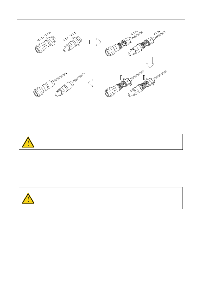
3.4.1 Connection of solar modules
Figure 3.8 Connection between DC connector and solar modules
Connection steps:
(1) Lighting, short-circuit and other protection measures which meet the local electrical safety
laws and regulations are needed before the AC connection;
Only qualified cables under the local electrical safety laws and regulations are
allowed to connect.
(2) Connect the out put cables of solar modules to the DC connector as figure 3.8 shows.
Loose the nut of connector and remove the isolation layer of the DC cable for about 15mm.
Insert it into the connector and press until heart the lock sound. Finally fasten the nut. The
wiring of negative pole is the same as that of the positive pole. Ensure the poles of solar
modules are well connected with the connectors;
The solar modules connected with the inverter needs to be the configured ones
other than some connecting devices without authorized. Otherwise, device
damage, unstable operation or fire may occur.
(3) Connect the DC connector with the inverter and ensure tightly-fastened;
(4) Insert the screw-driver into the hole of the connector to remove the connector form the
(5) Unclench the pressed cover with screw-driver to remove the cables from the connector.
inverter.
- 26 -

INVT iMars MG series grid-tied solar inverters Installation
OPEN
CLOSE
OPEN
CLOSE
OPEN
CLOSE
OPEN
CLOSE
L
PE
N
L
N
PE
3.4.2 AC connection of single-phase inverter
Figure 3.9 AC connection of single-phase inverter
Connection steps of single-phase inverter:
(1) Before connecting the single-phase AC grid cable to the inverter, take lightning and short circuit
protection measures in accordance with the local electrical safety codes;
(2) As shown in Figure 3.9, connect and fasten L, N and PE conductors of the single-phase
common grid to AC terminal, and then connect the terminal to the AC port of the inverter;
(3) Fix and connect the DC output cables of PV board with the matched DC connectors, and then
connect the connectors to the DC port of the inverter.
Only qualified cables under the local el ectrical safety laws and regulations are
allowed to connect.
- 27 -

INVT iMars MG series grid-tied solar inverters Operation
4 Operation
This chapter describes detailed operation of the inverter which involves the inspection before
operation, grid-tied operation, stopping and daily maintenance of the inverter.
- 28 -
INVT iMars MG series grid-tied solar inverters Operation
battery.
Run
Run
4.1 Inspection before operation
Check as follows before operation (including but not limited to):
(1) Ensure the installation site meet the requirement mentioned in section 3.2.2 for easy
installation, removing, operation and maintenance;
(2) Ensure the mechanical installation meet the requirement mentioned in section 3.4;
(3) Ensure the electrical installation meet the requirement mentioned in section 3.5;
(4) Ensure all switches are “off”;
(5) Ensure the voltage meet the requirement mentioned in section 2.4;
(6) Ensure all electrical safety precautions are clearly-identified on the installation site.
Do check as above before any operation if the system or inverter needs to be
installed, refitted and maintained.
4.2 Grid-tied operation
When power on the inverter for the first tim e, please refer to section 5.5 to
Note
Please start the inverter as follows:
(1) Ensure the requirements mentioned in section 4.1 are met;
(2) Switch on the breakers at the AC side;
(3) Switch on the integrated DC switch;
(4) Switch on the switch on the DC side;
(5) Observe the LED indicators and information displayed on the screen. Refer to chapter 5
self-inspection----successful commissioning.
“Warn” or “Fault” indicators are on or blinking: the inverter is power on, but fault occurs.
Please refer to section 5.3 for detailed information, and then stop as the section 4.3
mentioned, finally settle the problems as chapter 7. If all faults are solved, do as chapter 4
mentioned.
complete grid certification choice.
Keep the inverter power on at least 30 minutes to c harge for the internal clock
for detailed information.
Green indicator blinks, others off: the inverter is power on and in self-inspection;
Green indicator on, others off: the inverter is in power generation after
- 29 -
INVT iMars MG series grid-tied solar inverters Operation
contents
cycle
time monitoring software to read
running data, regularly back up all
make sure the parameters are set correctly.
solid, no damage or deformation. When
When inverter
the case cooling is normal.
See Section 4.4.2.
Check the cable connection and inverter
make sure they are connected
reliable.
4.3 Stopping
Stop the inverter as follows it needs maintenance, inspection and troubleshooting:
(1) Switch off the breakers at the AC side;
(2) Switch off the integrated DC switch;
(3) Switch off the switch on the DC side;
(4) Wait at least 5 minutes until the internal parts and components are discharged. And then
stop the inverter.
4.4 Daily maintenance
The inverter can perform power generation, start and stop automatically even the da y and night
shifts and seasons change in one year. In order to prolong the service life, daily maintenance and
inspection are needed besides following the instructions mentioned in this manual seriously.
4.4.1 Regular maintenance
Maintenance
Store the operation
data
Maintenance methods
Use realinverter
inverter running data and stats. Check the
monitoring software and inverter LCD screen to
Maintenance
Once each quarter
Check to make sure the inverter installation is
Check inverter
operation status
Clean the surface
Check electrical
connection
inverter running, check to make sure the sound
and variables are normal.
running, use thermal imager to check whether
Check the ambient humidity and dust around
inverter, clean the inverter when necessary.
terminals,
reliably, not loose, and no damage, insulation
Every six months
Every six months
Every six months
- 30 -

INVT iMars MG series grid-tied solar inverters Operation
contents
cycle
on feature of inverter: use
the inverter, do "off" and "on" operation, to
time, make sure monitoring software can
necessary replaced.
Maintenance
Check the security
features
Maintenance methods
Check the offmonitoring software or LCD and keyboard on
confirm its off-on feature intact. At the same
normally communicate with the inverter. Check
the warning label on or around the inverter, if
Maintenance
Every six months
4.4.2 Maintenance guide
Clean the inverter
Cleaning procedure is as follows:
(1) Disconnect the input and output switches.
(2) Wait ten minutes.
(3) Use a soft brush or a vacuum cleaner to clean the surface and the inlet and outlet of the
inverter.
(4) Repeat Section 4.1 operating content.
(5) Restart the inverter.
- 31 -

INVT iMars MG series grid-tied solar inverters Display panel
5 Display panel
This chapter describes the panel displaying and how to operate on the panel, which involves the
LCD display, LED indicators and operation panel.
- 32 -

INVT iMars MG series grid-tied solar inverters Display panel
Run
Warn
Fault
Run
Warn
Fault
Run
Warn
Fault
Run
Warn
Fault
Run
Warn
Fault
5.1 LED indicators
There are three LED indicators on the panel:
(1) “Run”, operation indicator, green;
(2) “Warn” recoverable fault indicator, yellow;
(3) “Fault”, unrecoverable fault indicator, red.
The inverter state includes 6 states of stand-by, self-inspection, power generation, recoverable
fault and unrecoverable fault; LED indicators are on, off and blinking. Please refer to table 5-1 for
detailed state of inverter and LED indicators state.
”: LED indicator is off;
“
“
” (green), “ ” (yellow), “ ” (red): LED indicator is blinking at every 0.25S or 0.5S;
“
(Green), “ ” (yellow), “ ” (red): LED indicator is on.
Table 5-1 Inverter state and LED indicators
Inverter state LED indicators Description
Stand-by
Self-inspection
Power
generation
Recoverable
fault
No power on. All indicators off.
Green indicator blinks in every 0.25s, others off.
Power on and ready for self-inspection
Green indicator keeps on, others off.
Grid-tied power generation.
(1) Grid-tied power generation, but clock fault (A007);
(2) Grid-tied power generation, but DC input fault
(A001 or E001);
(3) Grid-tied power generation,but fan fault(E006 or
E012);
Green and yellow indicator keeps on, others off.
Inverter stand-by. The public grid fault(A001, A003,
A004, A005or A006);
Yellow indicator blinks in every 0.5s, others off
- 33 -

INVT iMars MG series grid-tied solar inverters Display panel
Run
Warn
Fault
Run
Warn
Fault
Run
Warn
Fault
Run
Warn
Fault
Inverter state LED indicators Description
(1) Inverter stand-by. Temperature abnormal(E006);
(2) Inverter stand-by. DC input fault (E001);
Yellow indicator keeps on, others off
Hardware or software fault (E003, E004, E005, E008,
E009, E011, E013 or E015). De-couple the inverter
from the system before maintenance.
Unrecoverable
fault
Red indicator blinks in every 0.5s, others off
Current-leakage or unqualified output power energy of
the inverter (E007, E010, E014, E017, E018 or E020).
De-couple the inverter from the system before
maintenance.
Red indicator keeps on, others off
Artificial
turned off
Note
Please refer to chapter 5 and 7 for detailed fault information and troubleshooting.
Stop after the communication or panel command. All
indicators are on.
5.2 Operation panel
There are 4 buttons on the panel:
(1) “ESC”, exit and return ;
(2) “
”, back to the front page and data increasing;
”,to the next page and data decreasing;
(3) “
(4) “ENT”, enter.
The machine can be turned on and off by pressing the buttons: press "ESC" and "ENT"(about 3
seconds) at the same time, and then the quick start-up and stop is available.
- 34 -

INVT iMars MG series grid-tied solar inverters Display panel
LED indicator
LCD screen
Operation panel
Operation panel
Text Parameter
Display A
rea
Fault Code MenuStatus Area
Curve Graphic
Display A
rea
5.3 LCD screen
Figure 5.1 Operation panel
All information is displayed on the LCD screen. The background illumination of LCD screen will go
out to save power if there is not button operation in 15 seconds. But it can be activated by pressing
any button. Press “ENT” to enter into the main interface if the back ground illumination is on. All
parameters can be viewed and set on the interface.
There are main interface and menu interfaces on the LCD screen, of which the main interface is
the default one after power on, while the menu interfaces are used to watch and set parameters or
other manual operation, such as viewing the monitoring parameters, history record, system
information, statistics and fault information and setting the displayed language, time,
communication address, password and factory defaults.
The main interface of the LCD screen is shown as the figure above:
Figure 5.2 Main interface
(1) The curve displays the power changing at the current day;
(2) The words on the screen display the current key parameters of the inverter. Three lines of
words are displayed at a time, but if the inverter is in operation or stand-by state, the words
are rolling forward at every 3s. And the user can press “
- 35 -
” or “ ” to look up the

INVT iMars MG series grid-tied solar inverters Display panel
Main Menu
Monit Param
History
Statistics
Setup
System Info
Fault Info
Current State
E-tod
: 0Wh
$-tod: €0. 00
P-in : 0. 00kW
History 0
2012/01
/05 11:32: 16
A005: Grid under freq
information freely;
(3) 5 states of the inverter are displayed on the screen;
(4) If the inverter is in fault or warning state, up to 8 corresponding fault codes can be
displaying on the screen.
5.4 Functions operation
Most of the parameters can be viewed and set through the LCD screen and operation panel.
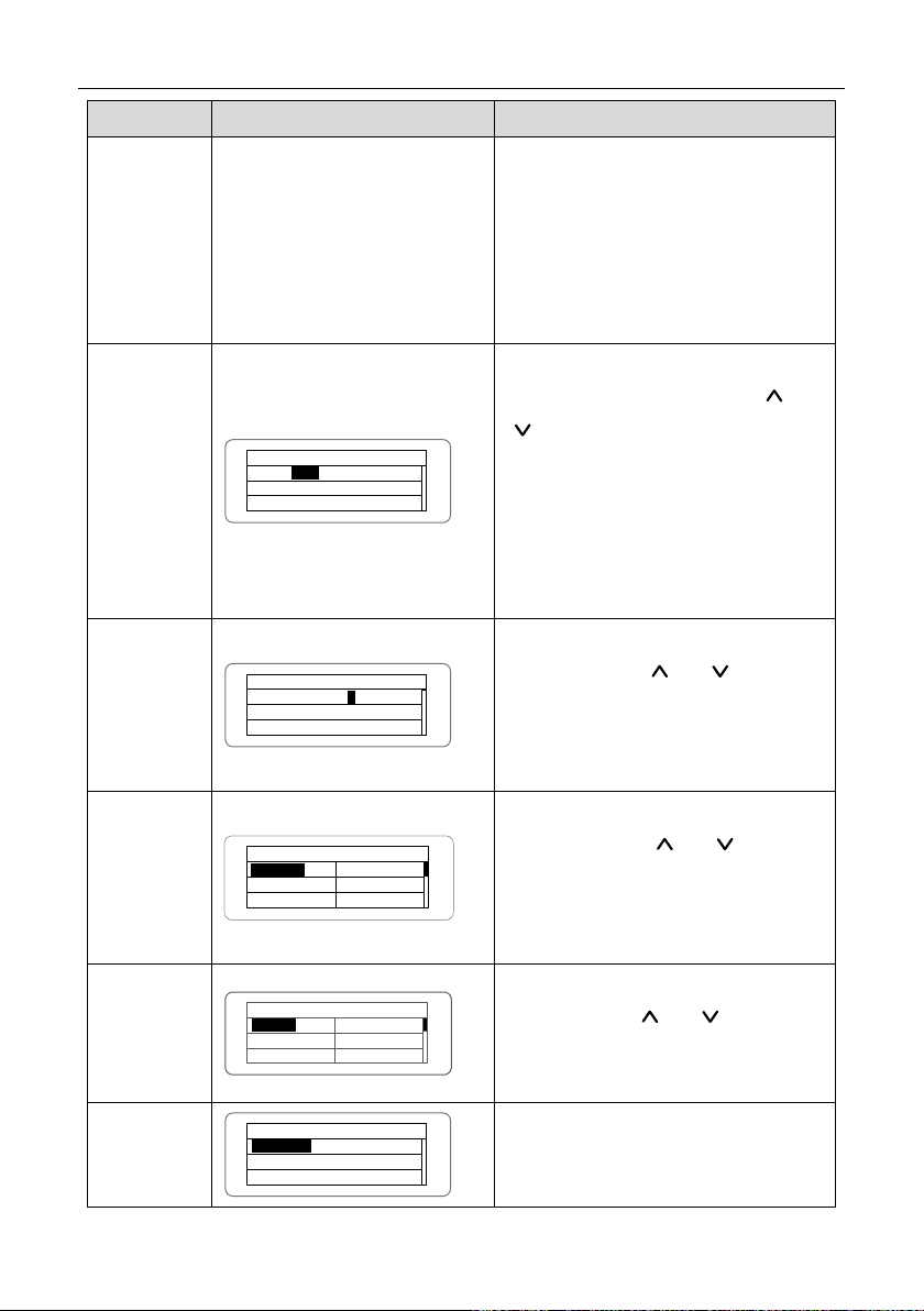
Figure 5.3 Main interface
5.4.1 Monitoring parameters
Press “ ” and “ ” in the main interface to select “Monit Param”, and then press “ENT” to view
the parameters which is shown in figure 5.4. Go the front or next page through “
return through “ESC”.
” and “ ” and
Figure 5.4 Monitoring parameters
5.4.2 History
Press “ ” and “ ” in the main interface to select “History”, and then press “ENT” to view the
parameters which is shown in figure 5.5.
Figure 5.5 History parameters
There are 32 history records in total. Press “
“ESC” to exit. The numbers on the top right is the serial No. of the record and the numbers in the
second line display date when faults occur and settled. If the color of the third line illuminates, the
fault occurs, if not, the fault is solved.
” and “ ” to review the history record and press
- 36 -

INVT iMars MG series grid-tied solar inverters Display panel
Statistical Menu
Lifetime
Partial
Today
Last 7 days
Last Month
Last 30days
Setup Menu
Address
Keypad PWD
Cash/price
Date/Time
Language
Set Model
5.4.3 Statistics
Press “ ” and “ ” in the main interface to select “Statistics”, and then press “ENT” to view the
parameters which is shown in figure 5.6.
Figure 5.6 Statistic information
The information in table 5-2 can be viewed in the statistical menu.
Table 5-2 Statistic information
Content Detailed
Lifetime
Total operation time, total power produced, total power saved, total CO
reduction in lifetime
2
Time statistics
Day statistics
Latest 7 days
Latest 1 month
Latest 30 days
Latest 1 year
Total power produced, total power saved, peak power and total CO
reduction in statistical time
Total power produced, total power saved, peak power and total CO
reduction in current day
Total power produced, total power saved and total CO
reduction in
2
latest 7 days
Total power produced, total power saved and total CO
reduction in
2
latest 1 month
Total power produced, total power saved and total CO
reduction in
2
latest 30 days
Total power produced, total power saved and total CO
reduction in
2
latest 1 year
5.4.4 Parameter settings
Press “ ” and “ ” in the main interface to select “Setup Menu”, and then press “ENT” to view
the parameters which is shown in figure 5.7.
Figure 5.7 Setting information
- 37 -
2
2

INVT iMars MG series grid-tied solar inverters Display panel
Current State
E- tod : 0 Wh
$- tod : €0. 00
P-in : 0. 00 kW
History 0
2012 / 01 / 05 11 : 32 : 16
A 005 : Grid under freq
Statistical Menu
Lifetime
Partial
Today
Last 7 days
Last Month
Last 30 days
Setup Menu
Address
Keypad PWD
Cash / price
Date / Time
Language
Set Model
Fault
1 : A 005 Grid under freq
2 : A 001 Input under Volt
3:
1
Control Menu
On / Off
Clear
Restart
Factory
Setup Menu
Address
Keypad PWD
Cash / price
Date / Time
Language
Country
RS 485 Address
001
1
User Password
0000
0
Setup Cash
Type : EUR
Val / kWh : 00 . 50 €/1 kWh
EUR
Setup Date / Time
Date : 2014 / 10 / 27
Time : 12 :14 :30
2
Setup Model : Independ
Independ
Parallel
User Period
Start : 2014 - 10 - 24
End : 2014 - 10 - 29
2
7
Main Menu
Monit Param
History
Statistics
Setup
System Info
Fault Info
V-pv 1 : 000 .0V
I -pv 1 : 000 .0A
V-pv 2 : 000 .0V
01. A001Alarm
p
h
Curr. Language : English
English
Chinese
German
Dutch
Country : Australia
Germany
England
Australia
Greece
Denmark
Holland
MENU
System Information
Part No .
Serial No .
Soft Ver
Cert . Area
Run Param
Parameters can be set in this interface.
LCD menus:
- 38 -

INVT iMars MG series grid-tied solar inverters Display panel
Control Menu
On / Off
Clear
Restart
Factory
On / Off Ctrl
ON
OFF
Clear all Record : Sure ?
Press ENT to execute .
Press ESC to cancel .
Restart
Press ENT to execute .
Press ESC to cancel .
Restore to Factory
Press ENT to execute .
Press ESC to cancel .
System Information
Part No .
Serial No .
Soft Ver
Cert . Area
Part No .
iMars BG 5 KTL
Serial No .
BGTL 100 - 00
System Ver
Version 1 : V 1 . 05
Version 2 : V 1 . 05
MCU Version
: V 1 . 05
Certificate Area
AS 4777
Run Param
Run Param
UV Volt .
UV time .
OV Volt
OV time
UF Freq
UF time
ACUV Time
200ms
RS
485 Address
001
1
User Password
0000
0
Table 5-3 Parameters setting
Setting item LCD display Instruction
RS485
Address
Enter into the interface and edit the data
through “
“ENT” again to the next bit. After editing
the three bits, press “ENT” to s ave the
edition and press “ESC” to exit.
Enter into the interface and edit the data
User
password
- 39 -
through “
“ENT” again to the next bit. After editing
the four bits, press “ENT” to save the
” or “ ”. And then press
” or “ ”. And then press
INVT iMars MG series grid-tied solar inverters Display panel
Setup Cash
Type: EUR
Val/
kWh: 00.50€/ 1 kWh
EUR
Setup Date
/Time
Date: 2012
/01/
15
Time:
12:14
:30
1
Curr. Language : English
English
Chinese
German
Dutch
Country : Australia
Germany
England
Australia
Greece
Denmark
Holland
Setup Model: Independ
Independ
Parallel
Setting item LCD display Instruction
edition and press “ESC” to exit.
The default password is “0000”; the user
can enter into the setting interface
without password. If the password is not
“0000”, the user can enter into the
setting interface with password.
Enter into the interface and edit the
currency type and cash through “
”. And then press “ENT” again to the
“
Setup Cash
next line. After editing the four bits, press
“ENT” to save the edition and press
“ESC” to exit.
The currency types include EUR, POD,
CNY and USD.
Enter into the interface and edit the date
Setup
Date/Time
and time through “
press “ENT” again to the next line. After
editing the four bits, press “ENT” to save
” or “ ”. And then
the edition and press “ESC” to exit.,
Enter into the interface and edit the
Language
language through “
press “ENT” again to save the edition
and press “ESC” to exit.
” or “ ”. And then
The default language is English.
Enter into the interface and select
Select
Country
country through “
” or “ ”. And then
press “ENT” again to save the edition
and press “ESC” to exit.
The DC input mode includes
Setup mode
- 40 -
“independent” and “parallel”:
“independent mode” is the independent
” or
INVT iMars MG series grid-tied solar inverters Display panel
User Period
Start
: 2012-01- 01
End : 2012
-02-01
1
Setting item LCD display Instruction
MPPT of Track A and Track B; “parallel
mode” is the parallel MPPT of Track A
and Track B.
The default mode is “independent”.
The input mode setting is invisible if the
inverter is in power generation. It is only
available during DC power on and AC
power off.
Press “
” or “ ” to select the setting
mode and press “ENT” to save the
setting or “ESC” to return.
If the situation of section 5.4.8 occurs, it
is necessary to switch the DC input to
“parallel” mode.
Enter into the interface and edit the user
period through “
” or “ ”. And then
press “ENT” again to the next bit. After
editing, press “ENT” to save the edition
and press “ESC” to exit.
User period
Of which, the setting time and date
needs to be later than the system
setting, and the start time needs to be
earlier than the end time.
The setting date and time is used for the
statistical information.
- 41 -
INVT iMars MG series grid-tied solar inverters Display panel
set power
P-Lmt
Mode
LmtPower
P.Factor
Limit Mode: Invalid
Invalid
Auto
Manual
Limit Power
100%
Power Factor
Grid Tied Mode
Normal Mode
Power Factor: 1.00
Input password
0000
Personal
MPP Start Volt
MPPT Volt
120V
Input password
0000
Setting item LCD display Instruction
The password is needed when enter into
the interface of “Set power”. Get the
password from the supplier if necessary
(supplier password: 2678). There are 3
submenus: ①P-Lmt Mode: invalid
(limited power function is invalid),auto
(special for single phase) ,manual (set
the limit of output value manually); ②
Set power
LmtPower: this function is only valid
when the P-Lmt Mode is manual, the
percentage is that of the rated power and
the setting range is from 10% to 100%;
③p.Factor: includes normal model
(default value “1”), current advanced
mode and current hysteresis mode and
the setting rage is -0.9-0.99.
(the machine of three phase only has the
function of ③)
This function is only valid for single
phase inverters. The password is
needed when enter into the personal
Personal
interface. Get the password from the
supplier if necessary (supplier password:
2678). It can set MPPT starting voltage
from 120V to 160V under the submenu
of ”MPPT start volt”.
- 42 -

INVT iMars MG series grid-tied solar inverters Display panel
Run Param
UV Volt
UV time
OV Volt
OV time
UF Freq
UF time
ACUV Volt(phase volt)
184V
ACUV Time
0.20s
ACOV Volt(phase volt)
263V
ACOV Time
0.20s
ACUF Freqency
47.6Hz
ACUF Time
0.20s
ACOF Freqency
51.4Hz
ACOF Time
0.20s
Input password
0000
Setting item LCD display Instruction
Password is required when enter into the
interface of “Run Param”. Get the
password from the supplier if necessary
Run Param
(supplier password: 2678). Set ACUV
Volt, ACUV time and others under the
related submenus, and then press “
and “
” to modify, and finally press
“ENT” to confirm.
”
- 43 -

INVT iMars MG series grid-tied solar inverters Display panel
Run Param
UV volt 1
UV time
1
OV volt 1
OV time
1
UF Freq 1
UF time 1
ACUV Volt(phase volt)
115V
ACUV Time
00.04
s
309V
00.02s
ACUF Frequency
47.99Hz
00.12s
50.50hz
00.12s
·
Input Password
0000
196V
252V
0.19s
01.90s
49.49Hz
595s
50.2Hz
115s
Run Restart Time
060s
Island protect:on
OFF
ON
ACOV Volt(phase volt)
ACOV Time
ACUF Time
ACOF Frequency
ACOF Time
ACUV Volt
(phase volt)
ACUV Time
ACOV Volt(phase volt)
ACOV Time
ACUF Frequency
ACUF Time
ACOF Frequency
ACOF Time
There are 2 protections under
Setting item LCD display Instruction
Run Param*
- 44 -
G83/G59(UK) and PEA(Thailand)
standards, and there is only one
protection under other grid tied standard.
Set ACUV Volt, ACUV time and others
under the related submenus, and then
press “
” and “ ” to modify, and
finally press “ENT” to confirm.
Generally, it is only necessary to set
ACUV and ACUF value for ACUV and
ACUF protection. And it is necessary to
set ACOF1 and ACOF2 together for
ACOF protection.

INVT iMars MG series grid-tied solar inverters Display panel
System Information
Part No .
Serial No .
Soft Ver
Cert . Area
Run Param
System Ver
Version1 : V1 . 05
Version
2 :
V1
.05
MCU Version
:
V
1.
05
Fault
1: A 005 Grid under freq
2: A
001 Input under Volt
3
:
1
Control Menu
On/
Off
Clear
Restart
Factory
5.4.5 System Information
Press “ ” and “ ” in the main interface to select “System Information”, and then press “ENT” to
view the parameters which is shown in figure 5.8.
Figure 5.8 System information
The system information include “product model”, “serial No.”, “software version” and “certificate
version”.
Figure 5.9 System version
5.4.6 Faults
Press “ ” and “ ” in the main interface to review the fault history, and then press “ENT” to view
the sub-menu which is shown in figure 5.10.
Figure 5.10 Fault information
There are 8 pieces of fault information in the record which is shown in figure 5.10; otherwise it will
display “No Fault!” Refer to section 5.4.2 for more detailed information.
5.4.7 Inverter control
Press “ ” and “ ” in the control interface, and then press “ENT” to view the sub-menu which is
shown in figure 5.11.
Figure 5.11 Control interface
- 45 -

INVT iMars MG series grid-tied solar inverters Display panel
On/Off Ctrl
ON
OFF
Restart
Press ENT to execute.
Press ESC to cancel.
Clear all Record: Sure
?
Press ENT to execute.
Press ESC to cancel.
is to clear all setting
Restore to Factory
Press ENT to execute.
Press ESC to cancel.
Refer to the table below for detailed information.
Table 5-4 Inverter control
Control item LCD display Instruction
Control the “On/Off” through the panel.
On/Off
control
Press “
interface to select the operation. Press
“ENT” to ensure the operation and press
” and “ ” in the control
“ESC” to return.
Restart the inverter through the panel.
And save the all settings and operation
Restart
record.
Press “ENT” to ensure restarting and the
inverter will begin to self-inspect or press
“ESC” to return.
Press “ENT” to ensure clear all records or
press “ESC” to return.
Record clear
“Record clear”
parameters through the panel, restore to
the factory setting and save all history
operation records.
“Restore to factory” is to clear all setting
Restore to
factory
parameters and history operation records
through the panel, restore to the factory
setting. Press “ENT” to ensure clear or
press “ESC” to return.
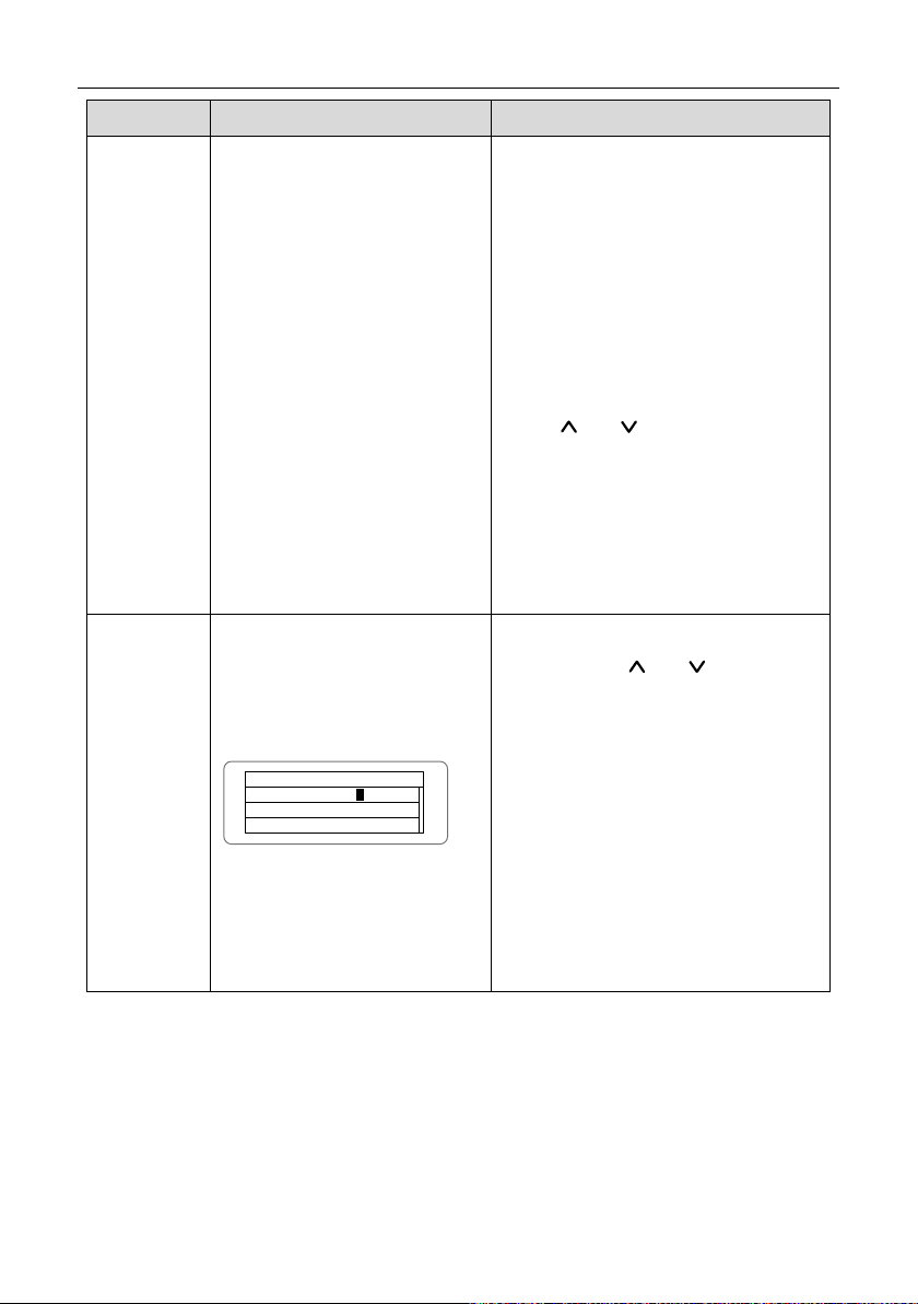
5.4.8 Mode settings
The default mode of series grid-tied solar inverter is “independent”. But if the current of solar
modules are joined into the inverter as figure 5.12 shows, it is necessary to switch the mode into
“parallel”.
- 46 -

INVT iMars MG series grid-tied solar inverters Display panel
screen and keypad.
SOLAR INVERTER
Initialing……Waiting
>>>>>>>
Country:
Unset
Germany
UK
Australia
Greece
Denmark
Holland
Country: Unset
Other
Denmark
Holland
China
Thailand
Greece
Figure 5.12 “Parallel” input mode
Only where there is more than 10 0V DC v oltage input, LCD dis play working, an d
Note
AC switch off, can query and modify the inverter DC input mode via the LCD
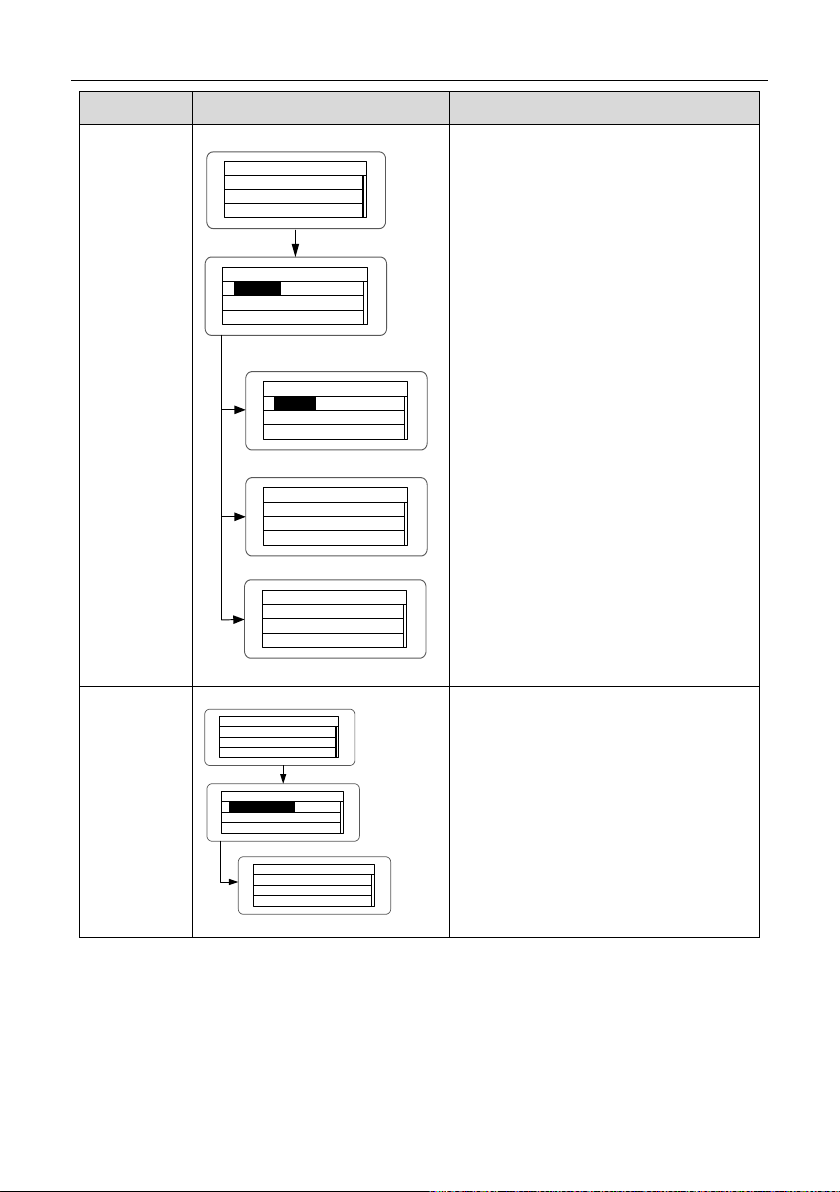
5.5 Grid Certification Choice
Power on the inverter by DC input for the first time or after Restore factory settings, it will appear
on the LCD screen prompts as follows:
Waiting a few seconds later, in the LCD screen will appear a list of countries as follows, requiring
the user to choose what country of use.
As shown below:
Press the “
” or “ ” button to navigate the country, press the ENT button to complete the
setting.
After determine the location, please follow the user manual required with the proper use of
inverter.
The user can change the location through the following ways:
LCD Screen:MENU→Main Menu: Setup→Setup Menu: Country→Country:
- 47 -

INVT iMars MG series grid-tied solar inverters Display panel
V-pv1: 000.0V
I -pv1: 000.0A
V-pv2: 000
.0V
01.A001
MENU
Alarm
p
h
MENU
Main Menu
Monit Param
History
Statistics
Setup
System Info
Fault Info
Setup Menu
Address
Keypad PWD
Cash/price
Date/Time
Language
Country
Country: China
Germany
UK
Australia
Greece
Denmark
Holland
V-pv1: 000.0V
I -pv1: 000.0A
V-pv2: 000.0V
01.A001
MENU
Alarm
p
h
MENU
Main Menu
Monit Param
History
Statistics
Setup
System Info
Fault Info
System Information
Part No.
Serial No.
Soft Ver
Cert. Area
Run Param
Certificate Area
AS4777
Germany
The user can query the grid certification which has been set through the following ways:
LCD Screen:MENU→Main Menu: System Info→System Information: Cert. Area→Certificate Area
Comparison Table: Available Countries and their grid certification
No. Country Certification Remark
1
VDE0126& AR-N4105
2 UK G83/G59
3 Australia AS4777
4 Greece VDE0126
5 Denmark TF321
6 Holland C10/C11
7 China CQC
8 Thailand PEA
9 Other VDE0126
- 48 -

INVT iMars MG series grid-tied solar inverters Display panel
Single-phase
voltage
Three-phase
voltage
Grid
frequency
New
Zealand
Reference Table: Grid Certification and Grid Voltage and Frequency of Some Countries
No. Country Certification
1 Germany
2 France
3 Greece
4 Turkey
5 Romania
6 Slovakia
7 Portugal
8 Poland
9 Hungary
10 Switzerland
11 Austria
12 UK G83-2/G59-3 240V 415V 50Hz
13 Australia
14 Singapore
15
16 Belgium
17 Luxembourg
18 Holland
19 Denmark TF3.2.1 220~230V 380~400V 50Hz
20 Thailand PEA 220V 380V 50Hz
21 China CGC/CF001 220V 380V 50Hz
22 Italy ENEL 230V 400V 50Hz
VDE0126&
AR-N4105
AS4777.2&AS4777.3
AS/NZS3100
C10/C11 220~230V 380~400V 50Hz
220~230V 380~400V 50Hz
230~240V 400~415V 50Hz
- 49 -

INVT iMars MG series grid-tied solar inverters Monitoring communication
6 Monitoring communication
This chapter describes the communication connection of inverter and monitoring system
(Industrial master, private computers, smart phones and so on).
- 50 -

INVT iMars MG series grid-tied solar inverters Monitoring communication
W
a
r
n
R
u
n
E
r
r
o
r
i
M
a
r
s
E
N
E
T
1
0
0
iMars E NET100
Inverter 001 Inverter 002
RS485
Inverter N
Ethernet
PhonExpert
WinExpert
Internet
WinExpert
WinExpert
Router
Router
User wired network
WiFi
PhonExpert
WinExpert
Internet
WinExpert
WinExpert
Router
Router
User wireless network
W
a
r
n
R
u
n
E
r
r
o
r
i
M
a
r
s
W
i
F
i
1
0
0
WiFi
iMars WiFi100
Ethernet wired monitoring system solution
WiFi wireless monitoring system solution
iMars Grid- tied Solar Inverter
InfoExpert
InfoExpert
InfoExpert
InfoExpert
RS485
RS485
Pin on inverter
Definition
1
+5VDC
2
A (RS485+)
3
B (RS485-)
4
GND
The standard communication mode of iMars grid-tied solar inverter is RS485 which includes
“RS485” and “EXT” ports. The two ports can both communicate with private computers, smart
phones and so on. The system monitoring solution are shown as figure 6.1.
6.1 Standard communication
Table 6-1 Pins on inverter instruction
Figure 6.1 Monitoring system of inverter
- 51 -
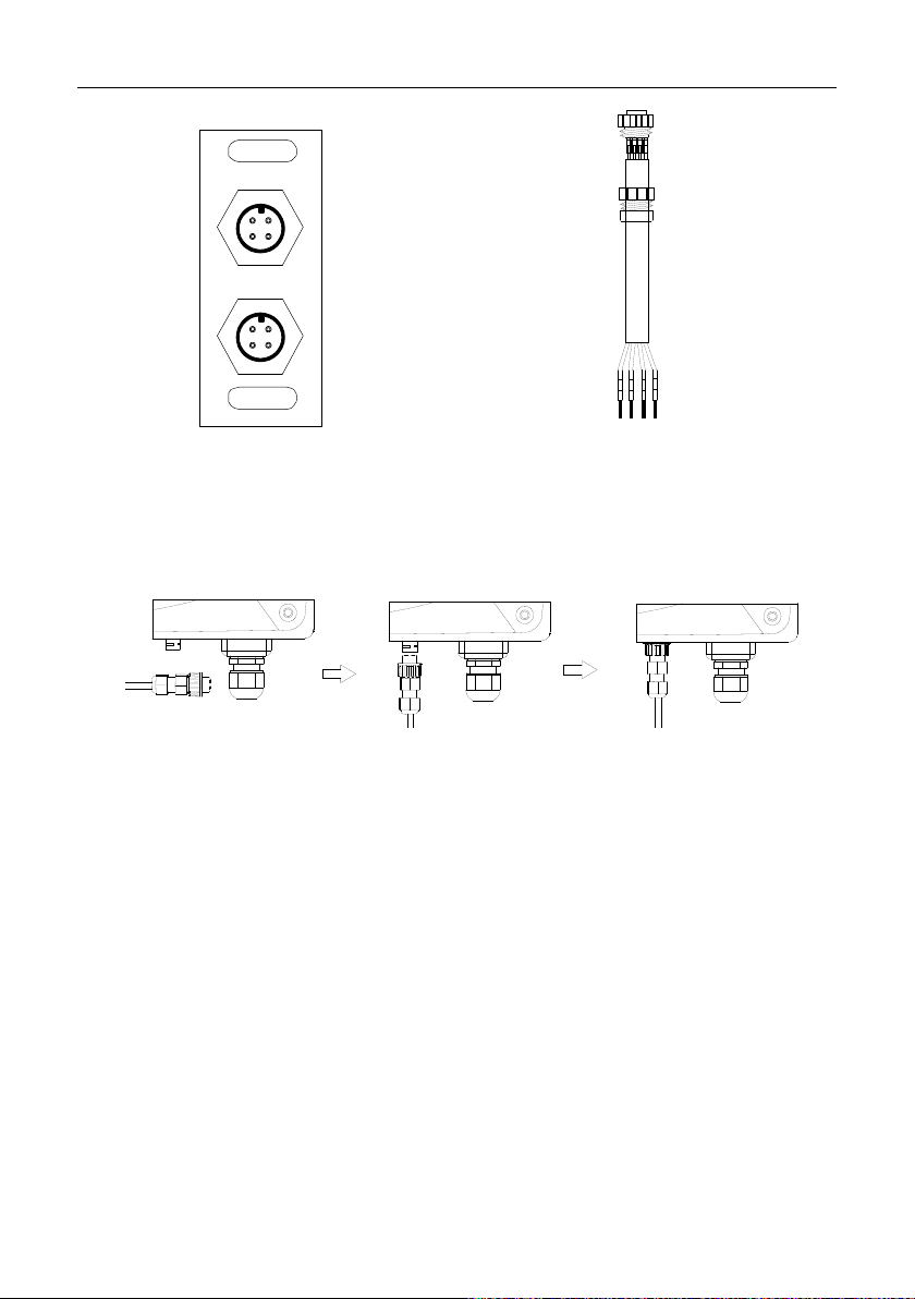
INVT iMars MG series grid-tied solar inverters Monitoring communication
RS
485
EXT
3
2
1
4
32
1
4
1
+5V
485+
485-
GND
23
4
Figure 6.2 RS485 pin on inverter Figure 6.3 Communication connector
Connection steps:
(1) Weld communication cables to the RS485 terminals of the inverter as figure 6.4
shows;Ensure the cable corresponds to the pin as table 6-1 shows and the welding is tight
enough.
Figure 6.4 Detailed connection
(2) According to Table 6-1, connect the communication connector pinout and the user's
device, make sure the connection is correct;
(3) Please download the monitoring software “iMars WinExpert” and its operation instruction
on www.invt-solar.com.
6.2 Optional communication
The optional communication modes include Ethernet, WiFi, which also need corresponding
communication parts and components. All operation parameters of the inverter are output from
port “RS485/EXT”, and then to the communication devices, finally after convertering, to the
monitoring system of upper PC as standard Ethernet, WiFi signal. See figure 6.1.
Table 6-2 Optional accessories
- 52 -

INVT iMars MG series grid-tied solar inverters Monitoring communication
Automatic control of data flow, automatic identification and
Optional accessories Inverter port Port of upper PC
Ethernet converter RS485/EXT RJ45 plug
WiFi converter RS485/EXT WiFi signal
Please download the connection instruction, operation manual and commissioning tools on
website www.invt-solar.com.
Note: the optional accessories are not standard-configured.
6.2.1 WiFi200 converter
6.2.1.1 WiFi200 Product Introduction
iMars WiFi200 communication converter has 1 RS485 and 1 WiFi communication port for the data
transmission. This product is based on the embedded module with general serial port which meets
the network standard, has built-in TCP/IP protocol stack for the transformation between the user
serial port and WiFi port. The traditional serial device can transfer the data through Internet without
any configuration modification. WiFi200 provides a complete and rapid solution of data
transmission for serial devices.
Table 6-3 iMars WiFi200 has the following features:
Interface Parameters function
1.
transmission direction of control data and no handshake signal
is needed
RS485
interface
WiFi
interface
2. Transmission speed 300~115200Baud
3. Up to 32 devices of RS485
4. the maximum transmission distance 1200m
5. Flow indicator
6. Half duplex mode
1. Support data exchange between RS485 - WiFi interface
2. Meet the 802.11 b/g/n wireless standard
3. Wireless network AP/STA
4. Security mechanismWEP/WPA-PSK/WPA2-PSK/WAPI
5. Barrier-free transmission distance 100m
- 53 -
INVT iMars MG series grid-tied solar inverters Monitoring communication
atically after the network disconnection,
Interface Parameters function
1. TCP Server, TCP Client, UDP mode and UDP Server mode
2. Operation interface, target IP address and interface can be set
in random
3. Disconnect autom
ensure the reliable TCP connection of the whole network
4. Support TCP/IP/UDP network protocol stack
5. IE configuration interface
Others
6. Operation mode, Transparent data transmission or agreement
transfer mode
7. Input power supply: 5VDC~12V/170mA~300mA and the power
is provided by the inverter directly
8. Working temperature: -20~70°C
9. Working humidity:10%-90%RH (no condensation)
10. Storage temperature: -40-80 ℃
11. Storage humidity: 5%-90%RH (no condensation)
12. Other frequency: 20MHz, 40MHz and automatic
WiFi200 is AP mode in the factory. It can be connected with the 485 communication interface of
inverters and visited by computer or mobile software.
6.2.1.2 Monitoring solutions
WiFi200 communication converter has 3 monitoring solutions to establish the solar power
generation system for different requirements:
The first solution: direct connection. Short distance site control is available.
The second solution: router LAN. Remote LAN monitoring is available.
The third solution: router internet. Remote access internet control is available.
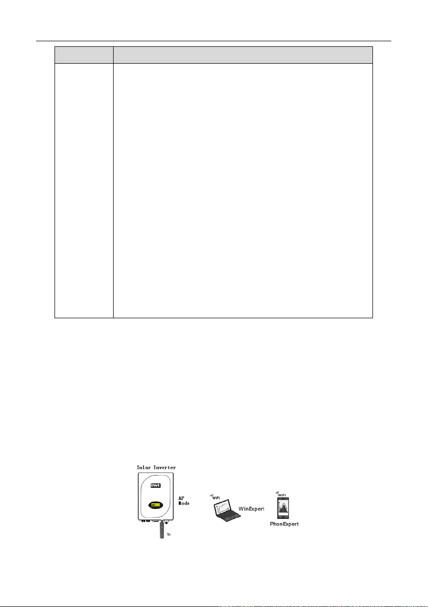
1. Direct connection
Figure 6.5 Direct connection solution
- 54 -

INVT iMars MG series grid-tied solar inverters Monitoring communication
Direct connection solution is suitable for short distance monitoring. The wiring is as the figure
above. Hardware and software devices such as iMars series solar inverters, WiFi200
communication converters, computers with the function of WiFi signal receiving), and WinExper t
solar monitoring software are needed in the establishment of direct solar monitoring. WiFi200
operates in AP mode which is also the default mode of the module. The monitoring device can visit
the inverter through wireless and wire modes. Refer to 6.2.1.3 for the configuration of WiFi200
communication converter and computers.
2. Router LAN
Figure 6.6 Router LAN solution
Router LAN is suitable for remote LAN monitoring. The wiring is as the figure above. Hardware
and software devices such as iMars series solar inverters, WiFi200 communication converters,
routers, devices with the function of WiFi signal receiving (such as computers and mobile phones)
are needed in the establishment of router internet monitoring. WinExpert solar monitoring software
or mobile phone APP are needed for the operation and data viewing.
Different configurations are needed in the wire or wireless connection between WiFi200 and
routers, monitoring devices and routers. Refer to 6.2.1.3 for detailed operation.
3. Router internet
Figure 6.7 Router internet solution
Router internet is suitable for internet monitoring without distance limit. But the servers of INVT
solar monitoring system are needed. The wiring is as the figure ab ove. Hardware and software
- 55 -

INVT iMars MG series grid-tied solar inverters Monitoring communication
devices such as iMars series solar inverters, WiFi200 communication converters, devices with the
function of WiFi signal receiving (such as computers and mobile phones) are needed in the
establishment of router internet monitoring. Websites or mobile phone APP are needed for the
operation and data viewing.
Different configurations are needed in the wire or wireless connection between WiFi200 and
routers, monitoring devices and routers. Refer to 6.2.1.3 for detailed operation.
6.2.1.3 Installation and commissioning
1. Computer network configuration
Take the computer configuration as the example. The user needs to ensure there is wireless
network card in the computer and the card can access the IP address automatically.
After power on, the factory default value is AP hotspot mode. Please connect the hotspot through
the wireless network and then the computer can access the IP address automatically.
2. Parameters setting
(1)Log in the Web
Open the web browser (need to use more than IE7.0 browser or Google Chrome browser), input
http//192.168.16.254 in the address bar. Input the user name: admin; Password: admin in the
pop-up login window and then click "Ok".
Enter into the main interface:
- 56 -
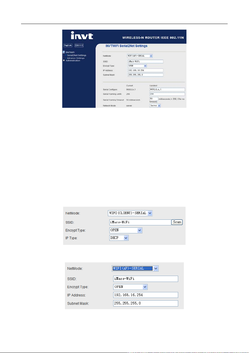
INVT iMars MG series grid-tied solar inverters Monitoring communication
There are 3 areas in the main Web interface: 1 Network configuration; 2 Serial port configuration; 3
Configuration submitting
Network modes (NetMode):
Default – default operation mode
ETH-SERIAL – serial port to Ethernet
WIFI (CLIENT)-SERIAL – serial port to WIFI CLIENT
WIFI (AP)-SERIAL) – serial port to WIFI AP
Different operation modes display different interface. The precious two modes can not be
supported by WiFi200, so mode (3) and (4) is introduced in this manual.
Serial port to WIFI CLIENT (STA mode):
Serial port to WIFI AP:
Serial port configuration:
- 57 -
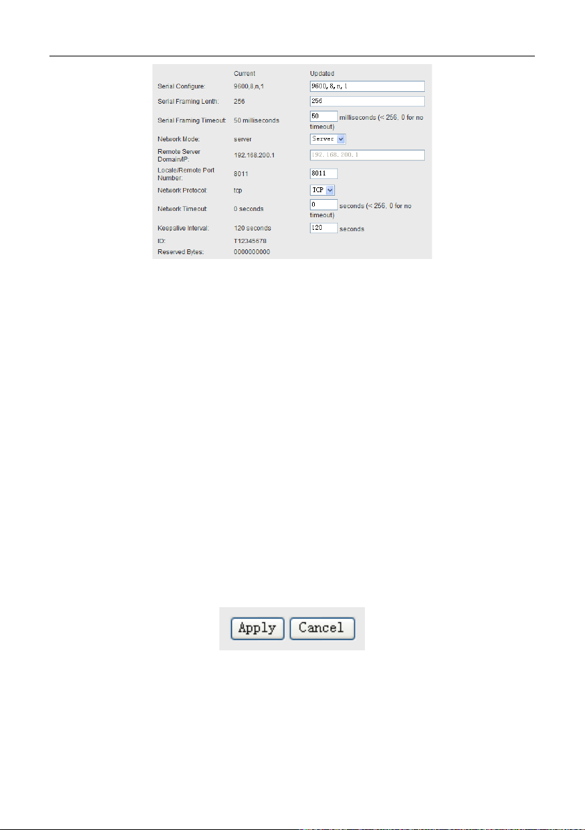
INVT iMars MG series grid-tied solar inverters Monitoring communication
Generally, above parameters does not need to be modified, and it can be adjusted during special
requirements.
Current: display the current configuration; Updated: display the current parameters to be modified.
Serial Configure: serial port configuration. The format is as below: baud rate, parity check, data
bits, stop bit, for example,“9600,8,n,1”
Serial Framing Lenth: framing length of the serial port
Serial Framing Timeout: framing time of the serial port
Network Mode: network mode, select Client, Server or none
Remote Server Domain/IP: The remote server domain name or IP address. For example,
192.168.200.1
Locale/Remote Port Number: Local or remote port number. Different network mode designates
different parameters. In the Client mode, it designates the remote port number and in Server mode,
it designates the local port number.
Network Protocol: Network Protocol type, use tcp or udp protocol
Network Timeout: Network Timeout. In Server mode, there is no data during the timeout
Configuration submitting:
Click “Apply” to submit the current interface. If the network parameters are modified, it needs 25
seconds to submit. If only modifying the function of serial port, the submitting will be finished soon.
Click “Cancel”to download the interface and the modified configuration will be lost.
(2)Configuration of direct monitoring
Select AP hotspot mode as the operation mode. SSID is the hotspot name and can be modified by
- 58 -

INVT iMars MG series grid-tied solar inverters Monitoring communication
the user. The authenticated encryption is OPEN, WEP, WPA and so on. The user c an set the
security according to the needs.
Select TCP Server in the configuration of the serial port.
(3)Configuration of router LAN monitoring
Select STA station spot mode as the operation mode. SSID is the hotspot name and the user
needs to modify it as the router name.
The user can use the button “Scan” to scan the wireless hot spots information and then the router
list can be found. The password and authentication encryption need to be set according to the
attribute of the wireless router.
Select TCP Server in the configuration of the serial port.
- 59 -

INVT iMars MG series grid-tied solar inverters Monitoring communication
(4)Configuration of router server
Select STA station spot mode as the operation mode. SSID is the hotspot name and the user
needs to modify it as the router name.
The user can use the button “Scan” to scan the wireless hot spots information and then the router
list can be found. The password and authentication encryption need to be set according to the
attribute of the wireless router.
Select TCP Server in the configuration of the serial port. Input the remote IP address according to
the actual. For example,“192.168.200.1”.
3. Commissioning
- 60 -
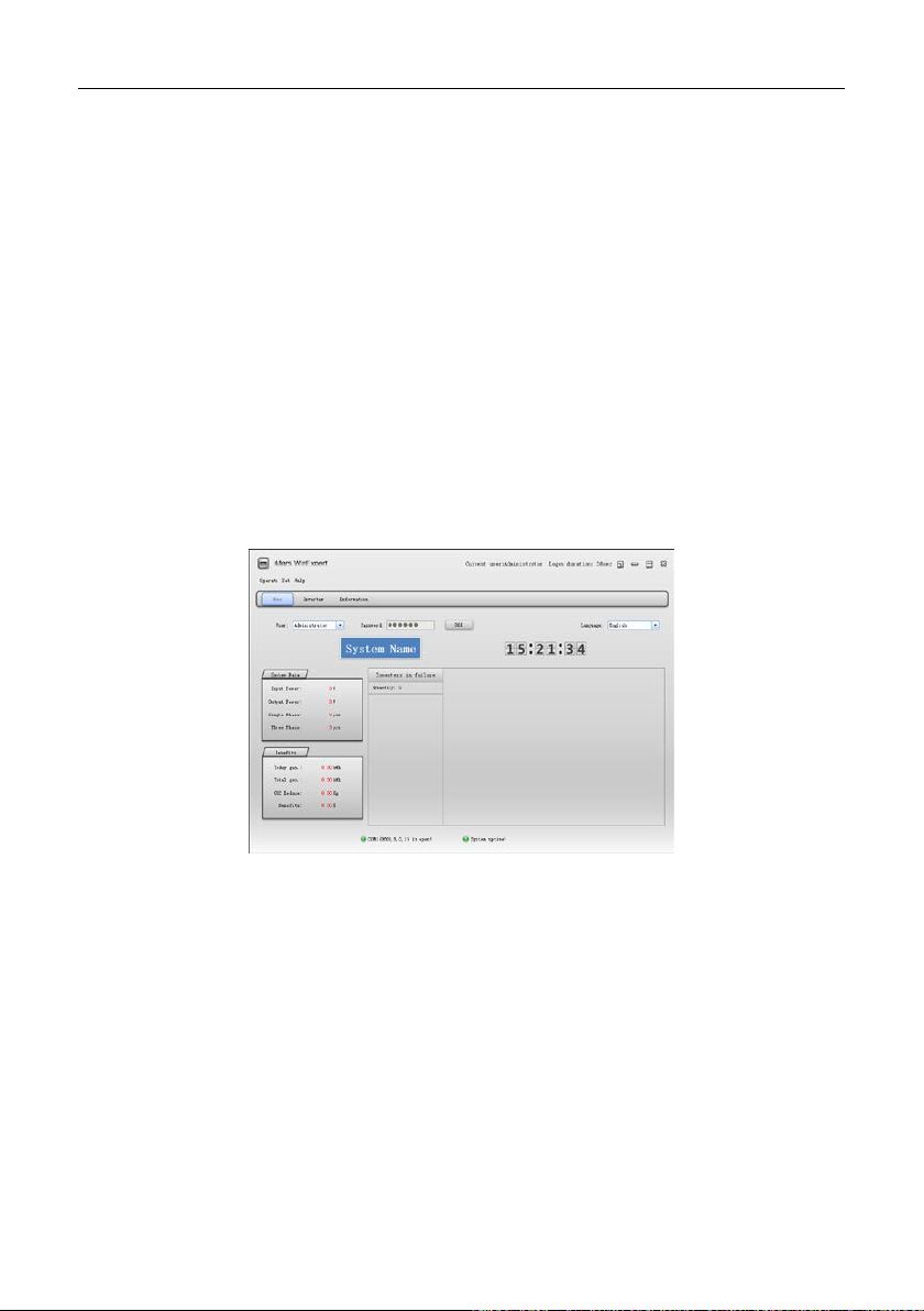
INVT iMars MG series grid-tied solar inverters Monitoring communication
The software of iMars WinExpert can check the configuration of WiFi200 and this method can be
used in the direct monitoring and router LAN monitoring.
Please download the monitoring software of iMars WinExpert and the operation instruction on
www.invt-solar.com.
WinExpert software introduction: WinExpert software can support two kinds of communication
mode of serial port and network. When WiFi100 monitors the inverter, it is necessary to select
network monitoring.
Note: because of 485 communication and the influence of the WiFi100 communication converter,
at the same time only one computer or mobile phone can transmit data with the inverter through
WiFi100 converter; otherwise there will be data conflict to make WinExpert or PhonExpert
monitoring software display the wrong data, and even lead to monitor software has burst
automatically and shut down.
Install WinExpert software on the computer (Microsoft XP or Win7 operating system).
Click "Set" menu to select "Set communicate information" menu.
- 61 -
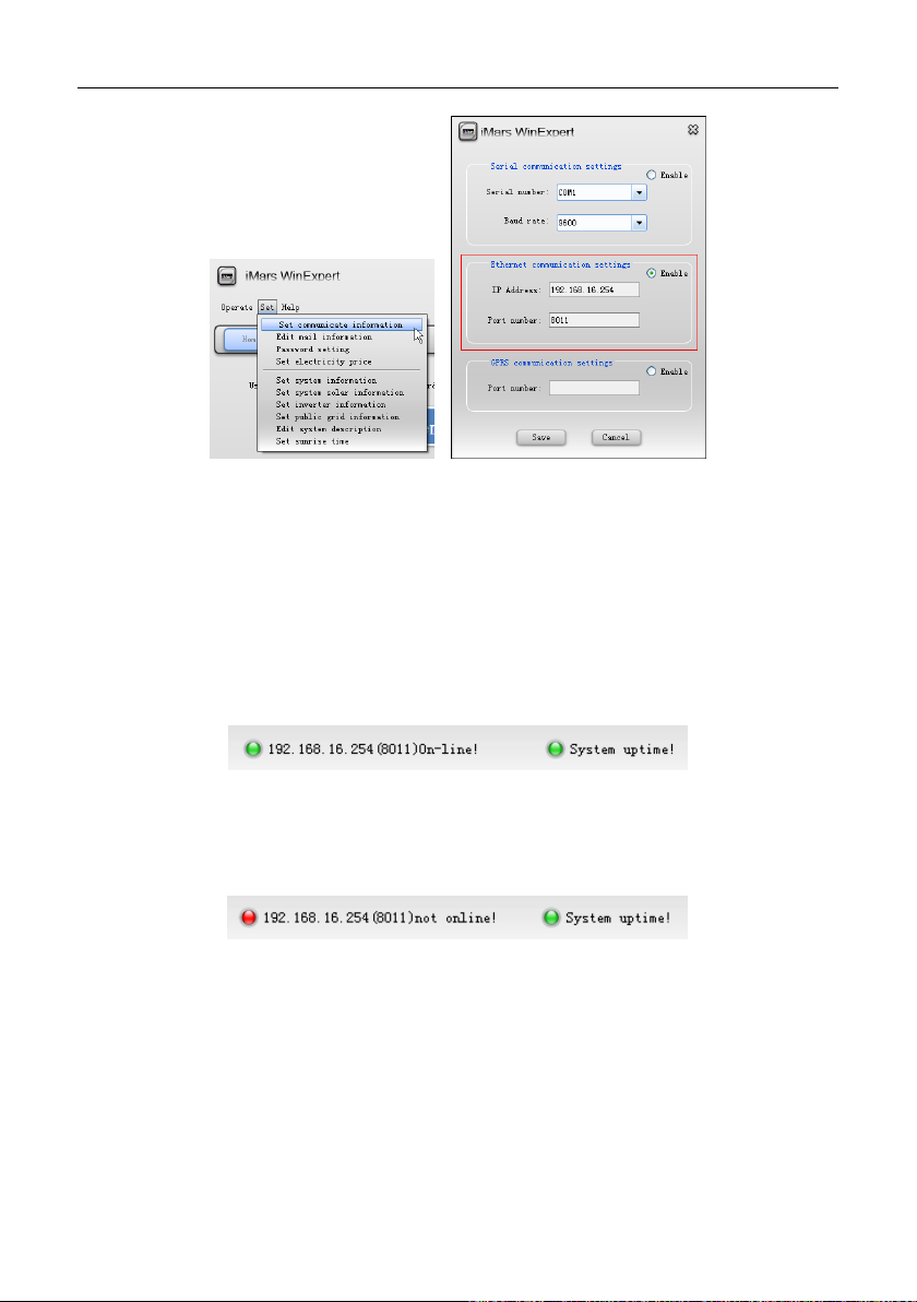
INVT iMars MG series grid-tied solar inverters Monitoring communication
Enable the “Ethernet communication settings” in the pop -up dialog box, fill in the IP address and
port number. The port number needs to be the same as that of the “Network setting”.
(1)Communication verification of WiFi200 and terminal devices
Complete the "Communication setting" of WinExpert solar monitoring software according to the
above description. As shown in figure, if the "green light" on the below of the home page is on and
display “Online”, the communication between WiFi200 and monitori ng devic es i s s uccess ful and i t
can go to the next step.
Otherwise, as shown in figure, if the "red light" on the below of the home page is on and display
“Offline”, the communication between WiFi200 and monitoring devices is not successful, please
check WiFi200 network connections, network configuration and monitoring equipment again.
(2)Communication verification of WiFi200 and inverters
Ensure the successful communication between WiFi200 and monitoring devices, and then check
the communication. As shown in the figure, select “Search inverter” in the operation menu of
WinExpert software.
- 62 -

INVT iMars MG series grid-tied solar inverters Monitoring communication
As shown in the figure, the inverter whose communication address in solar system is "001" inverter
has been displayed in the search list, which means the "001" inverter has successfully establish
communication with WiFi200. So on, when all the inverters in the solar system are displayed in the
search list, the solar system has successfully established communication with WiFi200. Otherwise,
please check the communication address and RS485 communication connec tion which are not
listed and repeat the above operation.
And then, the real-time data of the inverter can be monitored by the software.
- 63 -

INVT iMars MG series grid-tied solar inverters Troubleshooting
7 Troubleshooting
This chapter describes the fault alarm and fault code for quick troubleshooting.
- 64 -

INVT iMars MG series grid-tied solar inverters Troubleshooting
Table 7-1 Fault code
Fault
code
A
A001 Input UV Input undervoltage
A002 Bus UV Bus undervoltage DC input
A003 Grid UV AC undervoltage Low voltage of the public grid
A004 Grid OV AC overvoltage High voltage of the public grid
A005 Grid UF AC underfrequency Low frequency of the public grid
A006 Gri d OF AC overfrequency High frequency of the public grid
A007 Clock Fail Clock alarm Wrong setting
A009 Cmd Shut Manual stutdown
A011 Grid Loss
E
Message Instruction Fault analysis
PV1 undervoltage
PV2 undervoltage
Stop by the operation panel or upper
PC
The public grid
disconnects.
Check if inverter AC connection is
well
E001 Input OV Input overvoltage DC input overvoltage
E003 Bus OV Bus overvoltage Internal bus voltage
E004 Boost Fail Voltage-boost fault Voltage-boost fault of the inverter
E005 Grid OC AC overcurrent Internal AC overcurrent
E006 OTP Overtemperature Internal overtemperature
E007 Riso Low
E008 IGBT drv
Low isolation
impedance
IGBT drive
protection
Low isolation impedance of the
external port system
IGBT drive protection of the inverter
- 65 -

INVT iMars MG series grid-tied solar inverters Troubleshooting
Fault
code
E009 Int Comm
E010 ILeek Fail
E011 Relay Fault Relay fault Internal relay fault
E012 Fan Fail Fan fault Internal fan fault
E013 Eeprom Memory error Internal memory error
E014 Dc inject High DC injection High DC injection during AC output
E015 OutputShort Output short-circuit Output short-circuit
E018 Input OC Input overcurrent DC input overcurrent
E019 Incnst
E020 PowerReversed DC power reversed DC power reversed
Message Instruction Fault analysis
Internal
communication fault
Huge leakage
current
Data consistency
fault
Master-slave DSP communication
disabled
Error of master-slave DSP check bit
Huge leakage current of the system
or inverter
Inconsistent grid voltage, frequency,
leakage current or AC/DC injection
If any problem, please contact with the supplier and provide following information:
Model of the inverter: ;
Serial No. of the inverter: ;
System version:——version 1: ;
——version 2: ;
——MCU software version: ;
Fault code: ;
Fault description .
- 66 -

INVT iMars MG series grid-tied solar inverters Contact us
8 Contact us
Shenzhen·China
SHENZHEN INVT ELECTRIC CO., LTD
Add: No. 4 Building, Gaofa Scientific Industrial Park, Longjing, Nanshan District, Shenzhen, China
Tel: +86 755 86312953
Email: invtsolaros@invt.com.cn; invtsolarcn@invt.com.cn
Website: www.invt.com
Solar website:www.invt-solar.com
- 67 -

Warranty Card
Fault Messages:
iMars series inverter 2012
Consumer information (please print):
Name: Business name:
Address: Phone Number:
City: State: Zip Code:
Email:
Installer information:
Installer name:
Installation Company:
Contractor’s license number:
Address:
City: State: Zip Code:
Email:
Website:
Modules used:
Modules per string:
Number of strings:
System commission date:
Fault inverter information:
Model No.: Serial No.: Date of Delivery:
Error Code: Error tips:
Version1: Version2: MCU Version:
Signature:
Please mail or email a copy of this warranty registration card to:
Address:4# Building, Gaofa Industrial Park, Longjing, Nanshan District, Shenzhen, China 518055
Tel:86-755-86312953 Fax:86-755-86312880
Website:www.invt.com Email:inverter@invt.com.cn
All rights reserved by INVT. This information is subject to changes without notice.

INVT Warranty Terms and Conditions
INVT inverter provides five years’ quality assurance
*Please keep the whole warranty card and purchase invoice as the basis for quality assurance *
Standard warranty:
iMars MG Series inverter (Model: MG750TL/MG1KTL/MG1K5TL /MG2KTL/MG3KTL/MG4KTL/MG4K6TL/MG5KTL/MG3KTL-2M/
MG4KTL-2M/MG4K6TL-2M/MG5KTL-2M) from Shenzhen INVT Electric Co., Ltd. (herein after “INVT”). Have 60 months standard
warranty period starting on the date of Shipment by INVT.
Warranty extension:
The warranty period can be extended to 10 years from the date of shipment or no more than 126 months from the date of delivery
by INVT, subject to additional cost. INVT als o o ffers w arr anty extens i ons to 1 5 a nd 20 years (please check the separate order form) .
The warranty extension can be ordered while orders be confirmed and before shipment, and no more than twelve months after
delivery by INVT. Warranty extension is no longer possible after the above-mentioned dates. Upon purchase of the warranty
extension and once the unit has been delivered, INVT grants the customer a warranty certificate for each inverter confirming the
extended warranty period.
Procedure in the case of servicing:
Contact INVT or the authorized service agencies if your product is in the course of a defect or fault during the warranty period. To
file warranty claims and for claim management with INVT, you are required to supply us with following information and documents
regarding the fault inverter:
- Copy of the invoice and warranty certificate for the inverter.
- Copy of the startup report and startup date.
- Copy of warranty card (already filled out).
- Documentation detailing previous claims/exchanges (if applicable).
If a device becomes defective or fault during the specified INVT Factory warranty period, one of the following services, as selected
by INVT.
1) Depot Repair(For iMars inverter).
2) Exchange for a replacement device of equiv alent val ue accordi ng to mod el and ag e(Only for iMars inverter). In this case,
the reminder of the warranty entitlement will be transferred to the replacement device. In such an event, you do not receive
a new warranty card, as your entitlement is documented at INVT. INVT or the authorized service agencies will inform
replacement date within 2 working days. The defective device is to be packed in the original packaging materials for return
transport to the closest office of INVT.
Exclusion of warranty claims:
To provide better service to INVT’s End Users, all INVT authorized Dealers or Distributors are requested to respond to End Users’
warranty claim, and INVT will replace any products or parts of the product during the Warranty Period proved to be defective in
design or manufacture, provided always that the INVT’s obligations stated below will not apply where (the Dealers or Distributors
are liable for investigation of the fol l owing):
1) “Warranty Card” not being sent back to Distributor/Dealer or INVT;
2) Failure to observe the user manual, the installation guide, and the maintenance regulations;
3) Product modified or design changed or parts replaced not approved by INVT;
4) Transport damage, Painting scratch caused by shipping pumping, it should claim to insurance company as soon as
containers unload with enough evidence;
5) Modifications, changes, or attempted re pair s and er ase series number or seals by non INVT’s technician;
6) Failure to observe the applicable safety regulations (VDE standards, etc.);
7) Incorrect installation or commissioning;
8) The Product has been improperly stored and damaged while being stored by the Dealer or the end user;
9) Insufficient ventilation of the device;
10) The maintenance procedures relating to such product have not been observed or performed to an acceptable standard;
11) Incorrect use or inappropriate operation;
12) Force majeure (e.g., lightning, overvoltage, storm, fire).
Only INVT has the rights to revise the quality assurance contents mentioned-above; any trader or distributor has no rights to make
any modification for warranty card provided by INVT, or represent INVT to express any opinion and behavior; INVT reserves the
final interpretation right. If there is any question, users can dial the after-sales hotline.
Shenzhen INVT Electric Co., Ltd.

Quality certification
Inspector:
This product has passed inspection of our quality control and assurance department, and its
performance parameters meet the "User Manual" standard. Allowed to ex-factory sales!
Shenzhen INVT Electric Co.,

In dust ria l Auto mat io n:
Ele ct ric Power:
6 6 0 0 1 - 0 0 0 9 8
20 150 3 (V 2.0)
 Loading...