

Page 1
IVC3 Series PLC
Item
General-purpose IVC3
Program capacity
64 ksteps
High-speed input
200 kHz
High-speed output
200 kHz
Power-outage
memory
64 kB
CAN
The CANopen DS301 protocol (master) supports a
maximum of 31 stations, 64 TxPDOs, and 64
RxPDOs.
The CANopen DS301 protocol (slave) supports 4
TxPDOs and 4 RxPDOs.
Terminal resistor: Equipped with a built-in DIP switch
Station number setting: Set by using a DIP switch or
program
Modbus TCP
Supporting master and slave stations
IP address setting: Set by using a DIP switch or
program
Serial
communication
Communication mode: RS485
Max. baud rate of PORT1 and PORT2: 115200
Terminal resistor: Equipped with a built-in DIP switch
USB
communication
Standard: USB2.0 Full Speed and MiniB interface
Function: Program upload and download,
monitoring, and upgrade of underlying systems
Interpolation
Two-axis linear and arc interpolation (supported by
board software V2.0 or later)
Electronic cam
Supported by board software V2.0 or later
Special extension
module
Max. total number of special extension modules: 8
User name
Telephone
User address
Postal code
Product name and
model
Installation date
Machine No.
Product appearance or
structure
Product performance
Product package
Product material
Quality in use
Improvement
comments or
suggestions
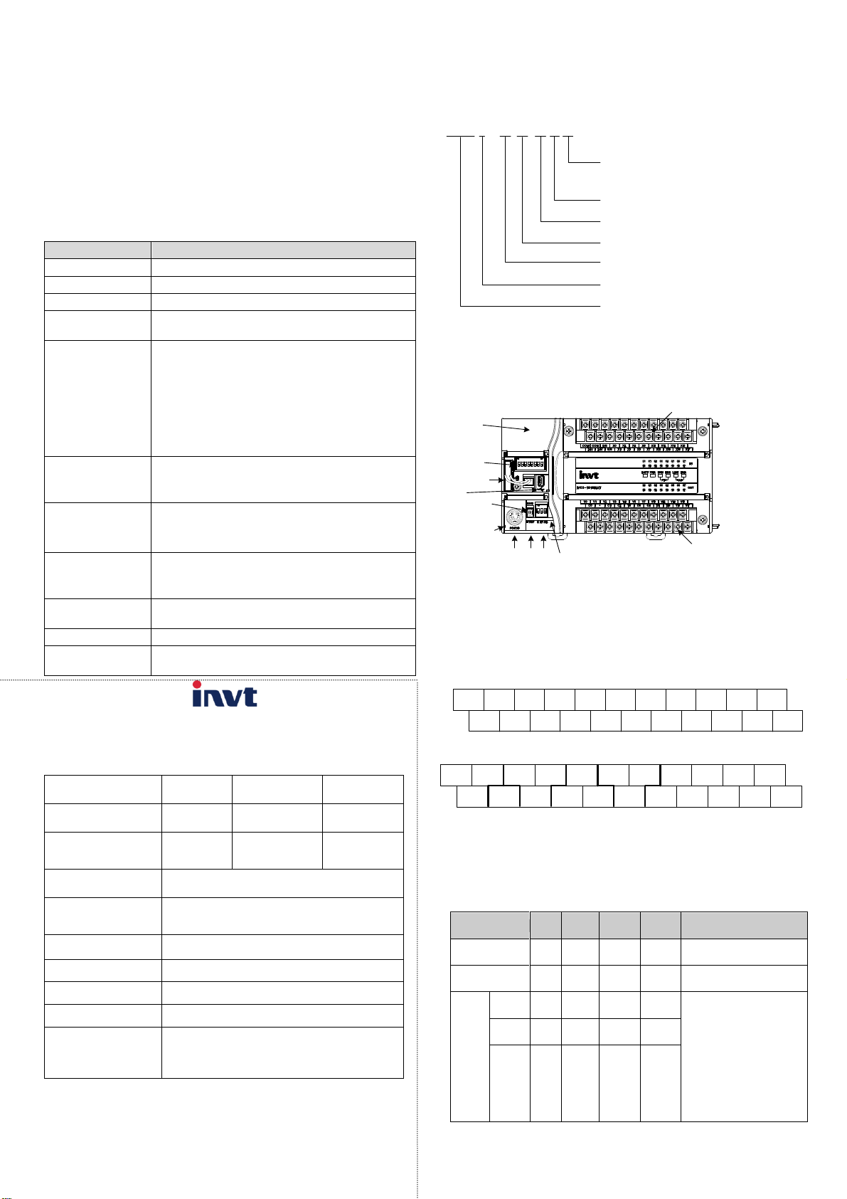
I V C 3 - 16 16 M A T
Identifier of INVT Auto-Control PLCs
Series number
Number of input points
Number of output points
Module type (M: Main module;
E: extension module)
Power input mode (A: 220 V AC power
input; D: 24 V DC power input; N: No
external power input)
Output mode (R: Relay output;
T: Transistor output; N: No output)
Signal input terminal
ETH
DIP switch for CAN
communication
Battery mounting
base
DIP switch for
running
PORT0
PORT1
PORT2
CAN
DIP switch for
terminal resistor
Signal output terminal
Input signal state indicator
System operation state indicator
Output signal state indicator
USB
COM
S/S
X0 X2 X4 X6 X10 X12 X14 X16
24V X1
X3
X7X5
X11 X13 X15 X17
COM
24V
S/S
Y0
Y1 Y2 Y3 Y4 Y6 Y7 Y10 Y12 Y14 Y16
C0
.
C1 C2
Y5
C4C3
Y11 Y13 Y15 Y17
Item
Unit
Min.
value
Typical
value
Max.
value
Remarks
Input voltage
range
V AC
85
220
264
Voltage range for proper
start and operation
Input current
A / /
1.5
90 V AC input, full-load
output
Rated
output
current
5V/GN
D
mA / 1000
/
The capacity is the sum of
the internal consumption
of the main module and
the load of the extension
modules. The maximum
output power is the sum
of the full load of all
modules, that is, 35 W.
The natural cooling mode
is adopted for the module.
24V/G
ND
mA / 650
/
24V/C
OM
mA / 600
/
Quick Reference Manual
Thanks for choosing the programmable logic controllers (PLCs) developed
and produced by INVT Auto-Control Technology (Shenzhen) Co., Ltd. Before
using the PLC, read this manual carefully to understand the product features,
so that you can use the product properly and make full use of its functions.
This manual briefly describes the hardware specification, features, and
application methods of IVC3 series PLCs. It is a quick-start guide for the
design, installation, connection, and maintenance of IVC3 series PLCs. Users
can handily refer to this manual for the required information on site.
1 Product introduction
1.1 Model description
Figure 1-1 describes the product model.
Customer service center
INVT Auto-Control Technology (Shenzhen) Co., Ltd.
Product quality feedback sheet
Figure 1-1 Product model description
1.2 Appearance and structure
Figure 1-2 shows the appearance and structure of an IVC3 series main
module (using IVC3-1616MAT as an example).
Figure 1-2 Appearance and structure
The bus socket is used to connect extension modules. The mode selection
switch provides three options: ON, TM, and OFF.
1.3 Terminal introduction
The following figures show the terminal arrangement of IVC3-1616MAT.
Input terminals:
Output terminals:
Gaofa Technology Park, Longjing, Nanshan District, Shenzhen
Postal code: 518055
2 Power supply specifications
Table 2-1 describes the specifications of the built-in power supply of the main
module and those of the power that the main module can supply to extension
modules.
Table 2-1 Power supply specifications
1
Page 2
3 Digital input/output characteristics
Item
High-speed input
terminals X0 to X7
Common input terminal
Signal input mode
Source-type or sink-type mode. You can select the
mode through the "S/S" terminal.
Electrical
paramet
ers
Detection
voltage
24V DC
Input
impedance
1 kΩ
5.7 kΩ
Input
switched on
The resistance of the
external circuit is lower
than 400 Ω.
The resistance of the
external circuit is lower
than 400 Ω.
Input
switched off
The resistance of the
external circuit is higher
than 24 kΩ.
The resistance of the
external circuit is higher
than 24 kΩ.
Filtering
function
Digital
filtering
X0–X7: The filtering time can be set through
programming, and the allowable range is 0 to 60
ms.
Hardware
filtering
Hardware filtering is adopted for ports except the X0
to X7, and the filtering time is about 10 ms.
High-speed function
Ports X0 to X7 can implement multiple functions
including high-speed counting, interrupting, and
pulse capture.
The maximum couting frequency of X0 to X7 is 200
kHz.
Item
Output specification
Output mode
Transistor output
The output is connected when the output state is ON,
and it is disconnected when the output state is OFF.
Circuit insulation
Optocoupler insulation
Action indication
The indicator is on when the optocoupler is drived.
Circuit power
supply voltage
5–24 V DC
The polarities are differentiated.
Open-circuit
leakage current
Lower than 0.1 mA/30 V DC
Min. load
5 mA (5–24 V DC)
Item
Output specification
Max.
outpu
t
curre
nt
Resistive
load
Total load of the common terminals:
Common terminal of the 0.3 A/1-point group
Common terminal of the 0.8 A/4-point group
Common terminal of the 1.6 A/8-point group
Inductive
load
7.2 W/24 V DC
Lamp load
0.9 W/24 V DC
Resp
onse
time
OFF→ON
Y0–Y7: ≤1 μs/higher than 10 mA
Others: ≤0.5 ms/higher than 100mA
ON→OFF
Max. output
frequency
Y0–Y7: 200 kHz (maximum)
Common output
terminal
One common terminal can be shared by a maximum
of 8 ports, and all the common terminals are isolated
from each other. For details about common terminals
of different models, see the terminal arrangement.
Fuse protection
No
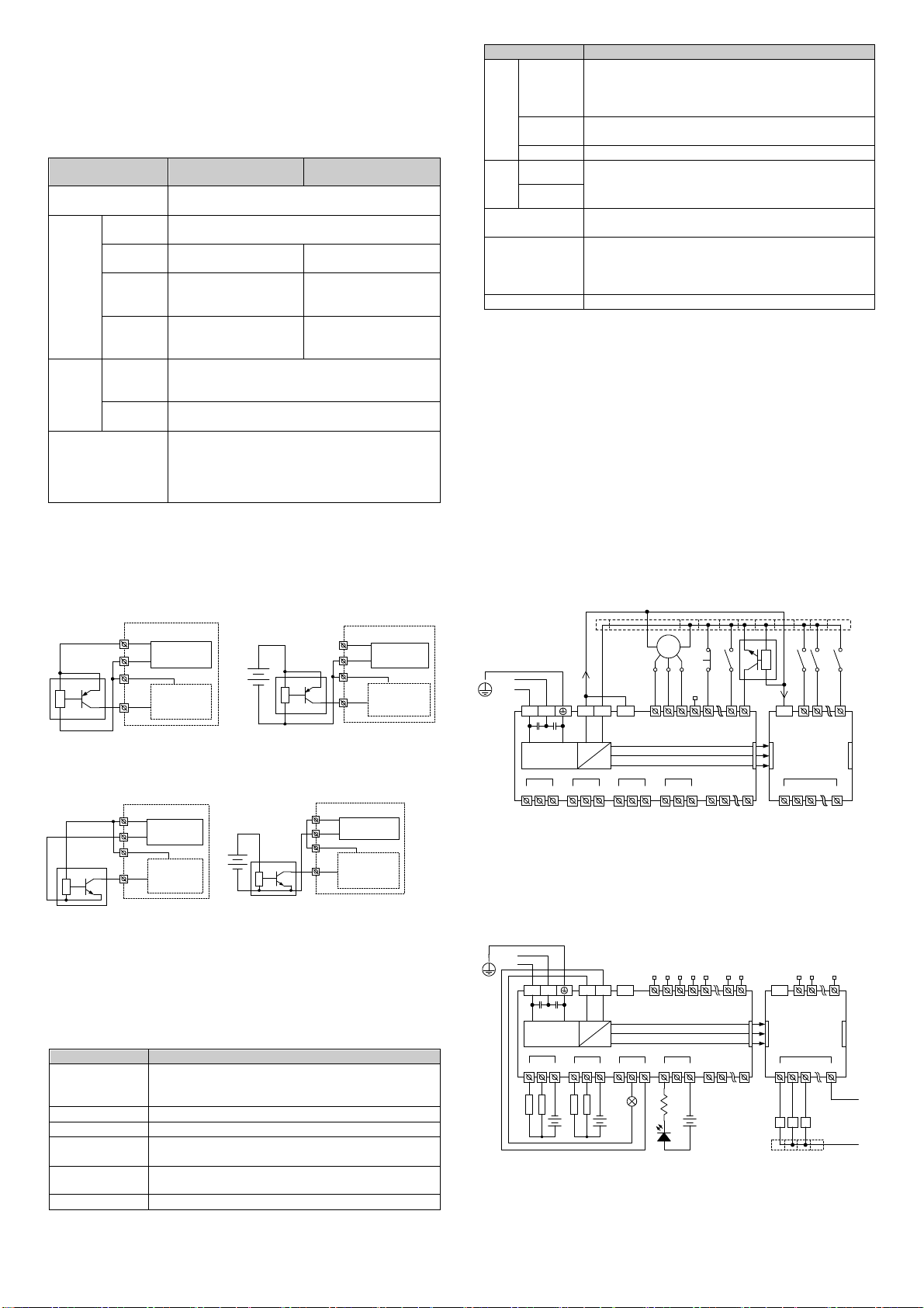
Source-type
wiring mode
S/S
X
+24V
COM
Isolation
circuit
24 V DC
Auxiliary
power supply
24V+
24V-
Sensor
Source-type
wiring mode
S/S
X
+24V
COM
Isolation
circuit
24 V DC
Auxiliary
power supply
24V+
24V-
Sensor
User-provided power supply
Wiring diagram of source-type input mode based
on the internal power supply of the module
Wiring diagram of source-type input mode
based on an external auxiliary power supply
Internal power supply
of the module
COM
+24V L N
Switch-mode
power supply
S/S
Y0
COM0
Y1
COM1
Y2
Y3
Y4
Y5
Y6
Y7
COM2
Y10
Y11
COM5
X0
X1
X2
X3
X4
X16
X17
IVC3-1616MAT
X0
X1
X7
+24V
Y0
Y1
COM0
Y2
IVC-EH-0808ENR
AC - N
AC - L
+24V
+5V
GND
传感器
Encoder
+24V
VGND
COM3
The common terminal
can be connected
through a terminal block.
COM
+24V N
Switch-mode
power supply
S/S
X0
X1
X2
X3
X4
X16
X17
IVC3-1616MAT
X0
X1
X7
+24V
Y0
Y1
COM
Y2
IVC-EH-0808ENR
A B
A B
A B
AC - L
AC - N
+24V
+5V
AC - N
L
Various low-voltage control circuits
The common terminal can be
connected through a terminal block.
220 V AC control load circuit
+24V
+5V
GND
Y0
COM0
Y1
COM1
Y2
Y3
Y4
Y5
Y6
Y7
COM2
Y10
Y11
COM5
COM3
L L L
L
+12V
+24V
AC - L
S/S
X
Internal power supply
of the module
Sensor
+24V
COM
Isolation
circuit
24V DC
Auxiliary
power supply
24V+
24V-
S/S
X
User-provided
power supply
Sensor
+24V
COM
Isolation
circuit
24 V DC
Auxiliary
power supply
24V+
24V-
Wiring diagram of sink-type input mode based
on the internal power supply of the module
Wiring diagram of sink-type input mode based
on an external auxiliary power supply
24 V DC
Sink-type
wiring mode
Sink-type
wiring mode
Figure 3-1 Source-type input wiring diagram
Figure 3-2 Sink-type input wiring diagram
Figure 3-3 Input connection instance
Figure 3-4 Output connection instance
3.1 Input characteristics and signal specifications
Table 3-1 describes the input characteristics and signal specifications.
Table 3-1 Input characteristics and signal specifications
(1) The transistor output circuit is equipped with a built-in voltage-stabilizing
tube to prevent the counter-electromotive force caused when the inductive
load is disconnected. If the capacity of the load exceeds the specification
requirement, you need to add an external freewheeling diode.
(2) High-speed transistor output involves distributed capacitance. Therefore, if
the machine runs at 200 kHz, you need to ensure that the conducted current is
larger than 15 mA to improve the output characteristc curve, and the device
connected to it can be connected to a resistor in parallel mode to increase the
load current.
3.3 Input/output connection instances
Input connection instance
The maximum frequency of the high-speed input port is limited. If the input
frequency exceeds the limit, the counting may be incorrect or the system fails
to run properly. You need to select a proper external sensor.
The PLC provides the "S/S" port for selecting the signal input mode. You can
select the source-type or sink-type mode. Connecting "S/S" to "+24V"
indicates that you select the sink-type input mode, and then an NPN-type
sensor can be connected. If "S/S" is not connected to "+24V", it indicates that
the source-type input mode is selected. See Figure 3-1 and Figure 3-2.
Figure 3-3 shows the connection of IVC3-1616MAT and IVC-EH-0808ENR,
which is an instance of implementing simple positioning control. The position
signals obtained by the encoder can be detected by the X0 and X1 high-speed
counting terminals. The position switch signals that require quick response
can be connected to the high-speed terminals X2 to X7. Other user signals
can be distributed among the input terminals.
Output connection instance
Figure 3-4 shows the connection of IVC3-1616MAT and IVC-EH-0808ENR.
The output groups can be connected to different signal voltage circuits, that is,
the output groups can operate in circuits of different voltage classes. They can
be connected only to DC circuits. Pay attention to the direction of the current
when connecting them.
3.2 Output characteristics and signal specifications
Table 3-2 describes the output electrical specifications.
Table 3-2 Output electrical specifications
2
Page 3
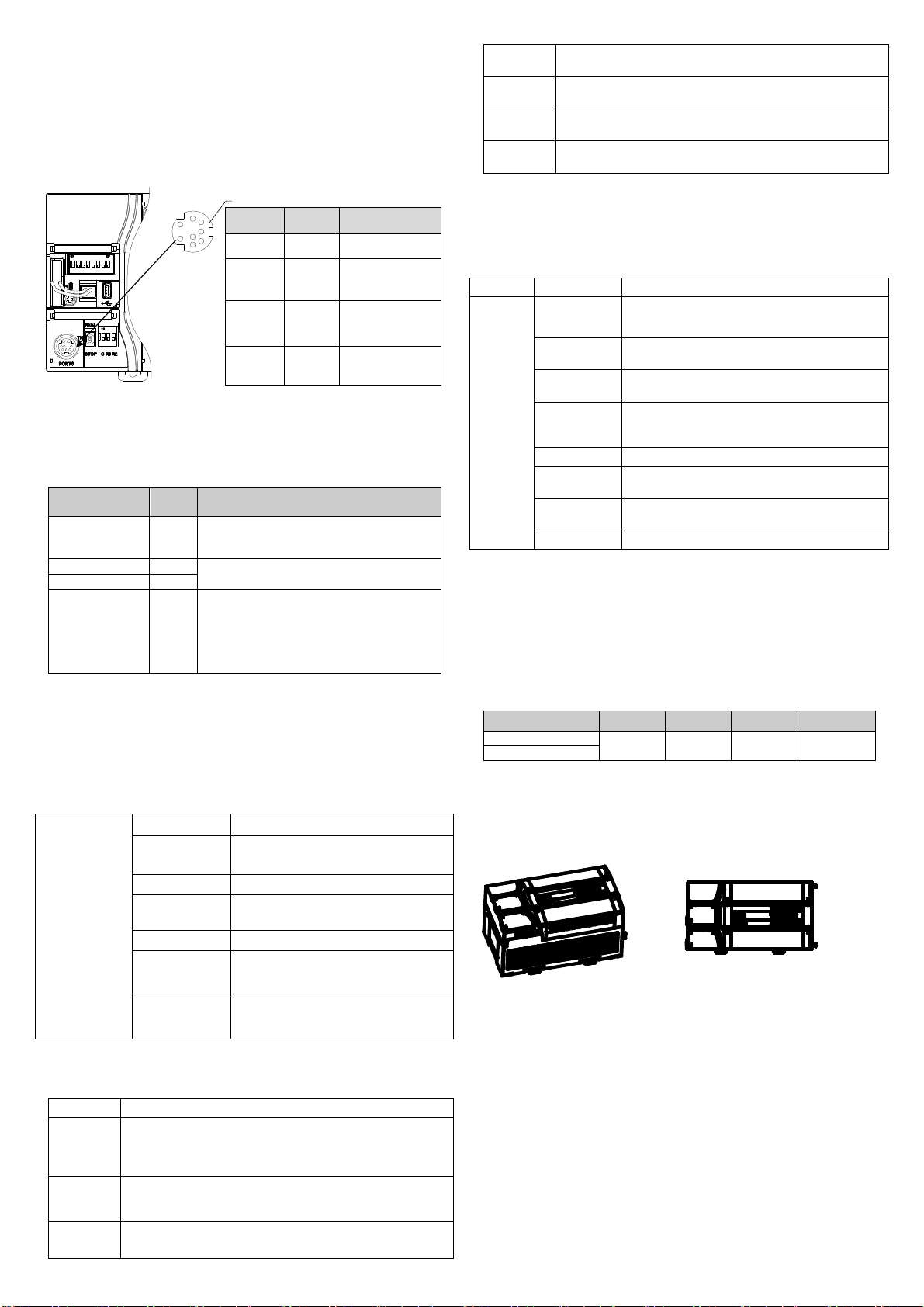
4 Communication guide
PORT0
12
345
67
8
Pin No. Name Description
3 GND Grounding pin
4 RxD
Serial data receiving
pin (from RS232 to the
PLC)
5 TxD
Serial data
transmitting pin (from
the PLC to RS232)
1, 2, 6, 7, 8 Reserved
Undefined pin
Do not connect to
these pins.
Mode selection
switch setting
State
PORT0 running protocol
ON
Running
Depend on the user program and its system
configuration. It can be the programming port,
Modbus, free-port, or N:N network protocol.
TM (ON→TM)
Running
Forcibly switched to the programming port
protocol.
TM (OFF→TM)
Stopped
OFF
Stopped
If the free-port protocol is used in the system
configuration of the user program, PORT0 is
automatically switched to the programming
port protocol after the PLC is stopped.
Otherwise, the protocol set in the system is not
switched.
RS485
communication
Item
Characteristic
Communication
port
2
Socket mode
PORT1, PORT2
Baud rate
115200, 57600, 38400, 19200, 9600,
4800, 2400, 1200bps
Signal level
RS485, half duplex, non-isolation
Supported
protocol
Modbus master/slave station protocol,
free communication protocol, N:N
protocol
Terminal
resistor
Equipped with a built-in DIP switch
Item
Characteristic
Protocol
Standard CANopen protocol DS301v4.02 that can be applied
for master and slave stations, supporting the NMT service,
Error Control protocol, SDO protocol, SYNC, Emergency, and
EDS file configuration
Master
station
Supporting 64 TxPDOs, 64 RxPDOs, and a maximum of 31
stations. The data exchange area (D component) is
configurable.
Slave
station
Supporting 4 TxPDOs and 4 RxPDOs
Data exchange area: SD500–SD531
Socket
mode
Pluggable terminal of 3.81 mm
Terminal
resistor
Equipped with a built-in DIP switch
Station
No. setting
Set through bits 1 to 6 of the DIP switch or through the
program
Baud rate
Set through bits 7 to 8 of the DIP switch or through the
program
Item
Characteristic
Ethernet
Protocol
Supporting the Modbus TCP and programming
port protocols
IP address
setting
The last segment of the IP address can be set
through the DIP switch or an upper computer
Slave station
connection
A maximum of 16 slave stations can be
connected simultaneously.
Master
station
connection
A maximum of 4 master stations can be
connected simultaneously.
Socket mode
RJ45
Function
Program upload/download, monitoring, and user
program upgrade
Default IP
address
192.168.1.10
MAC address
Set in factory. See SD565 to SD570.
Model
Width
Depth
Height
Net weight
IVC3-1616MAT
167 mm
90 mm
90 mm
740 g
IVC3-1616MAR
4.1 Serial communication
The IVC3 series main module provides three asynchronous serial
communication ports, namely PORT0, PORT1, and PORT2. They support the
baud rates of 115200, 57600, 38400, 19200, 9600, 4800, 2400, and 1200 bps.
PORT0 adopts the RS232 level and the Mini DIN8 socket. Figure 4-1
describes the pin definition of PORT0.
Use STPs for CAN communication. If multiple devices are involved in
communication, ensure that the GND terminals of all the devices are
connected and the terminal resistors are set to ON.
4.4 Ethernet communication
Table 4-4 Ethernet communication characteristics
Figure 4-1 Position of the mode selection switch and definition of PORT0 pins
As a specialized interface for user programming, PORT0 can be forcibly
switched to the programming port protocol through the mode selection switch.
Table 4-1 describes the mapping between PLC running states and PORT0
running protocols.
Table 4-1 Mapping between PLC running states and PORT0 running protocols
4.2 RS485 communication
Both PORT1 and PORT2 are RS485 ports that can be connected to devices
with communication functions, such as inverters or HMIs. These ports can be
used to control multiple devices in networking mode through the Modbus, N:N,
or free-port protocol. They are terminals fastened with screws. You can make
the communication signal cables by yourself. It is recommended that you use
shielded twisted pairs (STPs) to connect the ports.
Table 4-2 RS485 communication characteristics
5 Installation
IVC3 Series PLCs are applicable to scenarios with installation environments of
standard II and pollution level of 2.
5.1 Dimensions and specifications
Table 5-1 describes the dimensions and specifications of IVC3 series main
modules.
Table 5-1 Dimensions and specifications
5.2 Installation modes
Using DIN slots
4.3 CANopen communication
Table 4-3 CAN communication characteristics
Generally, the PLCs are installed by using DIN slots with a width of 35 mm, as
shown in Figure 5-1.
Figure 5-1 Diagram of installation by using a DIN slot
The specific installation steps are as follows:
1. Fix the DIN slot horizontally on the installation backplate.
2. Pull out the DIN slot clamping buckle from the bottom of the module.
3. Mount the module onto the DIN slot.
4. Press the clamping buckle back to where it was to lock the fix the module.
5. Use the stoppers of the DIN slot to fix the two ends of the module,
preventing it from sliding.
These steps can also be used to install other PLCs of the IVC3 series by using
DIN slots.
Using screws
For scenarios where large impact may occur, you can install the PLCs by
using screws. Put the fastening screws (M3) through the two screw holes on
the housing of the PLC and fix them on the backplate of the electrical cabinet,
as shown in Figure 5-2.
3
Page 4
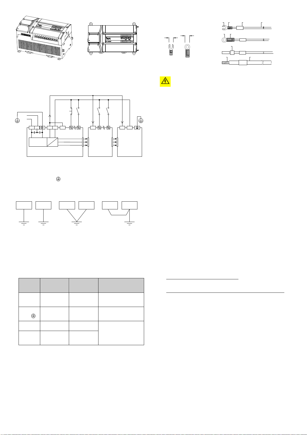
Figure 5-2 Diagram of installation by using screws
Cable
Coss-sectional
area of wire
Recommended
wire model
Cmpatible wiring
terminals and
heat-shrinkable tubing
AC power
cable (L, N)
1.0–2.0mm²
AWG12, 18
H1.5/14 preinsulated
tube-like terminal, or hot
tin-coated cable terminal
Grounding
cable ( )
2.0mm²
AWG12
H2.0/14 preinsulated
tube-like terminal, or hot
tin-coated cable terminal
Input signal
cable (X)
0.8–1.0mm²
AWG18, 20
UT1-3 or OT1-3
cold-pressed terminal, Φ3
or Φ4 heat-shrinkable
tubing
Output
signal
cable (Y)
0.8–1.0mm²
AWG18, 20
Less than 5.0
Less than5.0
UT Cold-pressed
terminal
Heat-
shrinkable
tubing
Wire No. Wire
OT Cold-pressed
terminal
Heat-shrinkable tubing
H-type preinsulated
cold-pressed terminal
Hot tin-coated
cable terminal
Wire
PG
18
47
682
Warning
COM
+24V L N
Switch-mode
power supply
S/S
X0
X17
IVC3-1616MAT
X0
X7
+24V
IVC-EH-0808ENR
AC - N
AC - L
+24V
+5V
GND
COM
+24V
IVC3 series
special function
module
PLC
Other
devices
Optimal
PLC
Other
devices
Good
PLC
Other
devices
Worst
Figure 5-3 Connection diagram of the AC and auxiliary power supplies
Figure 5-4 Grounding diagram
5.3 Cable connection and specifications
Figure 5-5 Cable preparation diagram
Power cable and grounding cable connection
Figure 5-3 shows the connection of the AC and auxiliary power supplies.
The anti-electromagnetic interference capability of the PLCs can be improved
by configuring reliable grounding cables. When installing a PLC, connect the
power supply terminal
connection wires of
to the ground. It is recommended that you use
AWG12 to AWG16 and try to shorten the wires, and that you
configure independent grounding and keep the grounding cables away from those of
other devices (especially those generating strong interference), as shown in Figure
5-4.
Cable specifications
For the wiring of the PLC, it is recommended that you use multi-stranded
copper wire and prepare insulated terminals to ensure the wiring quality. Table
5-2 describes the recommended wire cross-sectional areas and models.
Fix the processed cable terminals onto the wiring terminals of the PLC by
using screws. Pay attention to the positions of the screws. The tightening
torque for the screws is 0.5 to 0.8 Nm, which can be used to complete reliable
connection without damaging the screws.
Figure 5-5 shows the recommended cable preparation mode.
Table 5-2 Recommended cross-sectional areas and models
Do not connect transistor output to AC circuits, such as a circuit of 220 V AC.
Strictly follow the electrical parameters to design the output circuits. Ensure
that no overvoltage or overcurrent occurs.
6 Power-on, operation, and routine
maintenance
6.1 Power-on and operation
After the wiring is complete, check all the connections. Ensure that no foreign
matters have dropped inside the housing and heat dissipation is in good
conditions.
1. Power on the PLC.
The POWER indicator of the PLC is on.
2. Start the Auto Station software on the PC and download the compiled user
program to the PLC.
3. After the program is downloaded and verified, set the mode selection
switch to ON.
The RUN indicator is on. If the ERR indicator is on, it indicates that errors
occur on the user program or the system. In this case, rectify the errors by
referring to the instructions in the IVC Series Small-sized PLC
Programming Manual.
4. Power on the PLC external system to perform commissioning on the
system.
6.2 Routine maintenance
Pay attention to the following aspects when performing routine maintenance
and inspection:
1. Ensure that the PLC operates in a clean environment, preventing foreign
matters or dust from dropping into the machine.
2. Keep the PLC in good ventilation and heat dissipation conditions.
3. Ensure that the wiring is properly performed and all the wiring terminals
are well fastened.
User notice
1. The warranty covers only the PLC machine.
2. The warranty period is 18 months. We provide free-of-charge
maintenance and repairs for the product if it is faulty or damaged during
proper operation within the warranty period.
3. The warranty period starts from the ex-factory date of the product. The
machine No. is the only basis for determining whether the machine is
within the warranty period. A device without the machine No. is deemed
out-of-warranty.
4. Maintenance and repair fees are charged in the following scenarios even
the product is within the warranty period:
• Faults are caused due to misoperations. Operations are not performed
following the instructions provided in the manual.
• The machine is damaged due to causes such as fire, flood, or voltage
exceptions.
• The machine is damaged due to improper use. You use the machine to
5. The service fees are calculated based on the actual fees. If there is a
6. Keep this warranty card. Show it to the maintenance unit when you seek
7. Contact the local dealer or directly contact our company if you have any
Customer Service Center (China)
INVT Auto-Control Technology (Shenzhen) Co., Ltd.
Address: Gaofa Technology Park, Longjing, Nanshan District, Shenzhen
Postal code: 518055
Company website: http://www.invt-control.com/en/index.html
Version: V1.2 Date: 2018-08-17
All rights reserved. The content of this manual is subject to change without
prior notice.
perform some unsupported functions.
contract, the provisions stated in the contract prevail.
maintenance services.
questions.
4
 Loading...