

Page 1
(SJEUJFE4PMBS*OWFSUFS
Operation Manual
iMars
(
INVT Solar Technology (Shenzhen) Co., Ltd.
Page 2

1
Page 3

Preface
The manual is intended to provide detailed information of product information, installation,
application, trouble shooting, precautions and maintenance of iMars series grid-tied solar inverters.
The manual does not contain all the information of the photovoltaic system. Please read this
manual carefully and follow all safety precautions seriously before any moving, installation,
operation and maintenance to ensure correct use and high performance of operation on the
inverter.
The use o f the iMa r s series grid-tie d solar inver te rs mu st com ply w ith local law s and re gula t io n s on
grid-tied power gene ration.
The man u al n eeds t o be kep t well and be avail ab le at all tim es.
All rights reserved. The contents in this document are subject to change without notice.
Ther e may be d ata d eviati on becaus e of pr oduct i mprovi ng. Det ail ed inform ation is in acc ordant
with the final product.
Page 4

iMars grid-tied solar inverters Contents
Contents
Preface .................................................................................................................................................. 1
Contents................................................................................................................................................ 2
1 Safety precautions .............................................................................................................................. 5
1.1 Icons ...........................................................................................................................................................6
1.2 Safety guidelines .....................................................................................................................................6
1.2.1 Deliver y a nd instal l a t i on....................................................................................................................7
1.2.2 Grid-tied operation ............................................................................................................................8
1.2.3 Maintenance and inspection ............................................................................................................8
1.2.4 What to do after scrapping ...............................................................................................................9
2 Product overview.............................................................................................................................. 10
2.1 Solar grid-tied power generation system ........................................................................................ 11
2.2 Products appearance .......................................................................................................................... 13
2.3 Nameplate ............................................................................................................................................. 14
2.4 D RM instruction .................................................................................................................................... 15
2.5 Products modules ................................................................................................................................ 16
2.6 Dim ens i ons and w eig ht....................................................................................................................... 17
3 Storage ............................................................................................................................................. 18
4 Installation ....................................................................................................................................... 19
4.1 Unpacking inspection .......................................................................................................................... 20
4.2 Before in stallation ................................................................................................................................ 20
4.2.1 Ins tallat ion tools........................................................................................................................... 20
2
Page 5

iMars grid-tied solar inverters Contents
4.2.2 Ins tallat ion plac e ......................................................................................................................... 21
4.2.3 Connection cables ...................................................................................................................... 22
4.2.4 M ini ature cir c ui t breaker s .......................................................................................................... 23
4.3 Mechanical installation ........................................................................................................................ 23
4.3.1 Installation of three-phase inverter .............................................................................................. 23
4.4 Electrical installation ............................................................................................................................ 26
4.4.1 Connection of solar modules.................................................................................................... 27
4.4.2 AC c onn ec t i on ............................................................................................................................. 29
5Operation .......................................................................................................................................... 30
5.1 Inspection before operation ............................................................................................................... 31
5.2 G rid-tied operation ............................................................................................................................... 31
5.3 Stopping ................................................................................................................................................. 32
5.4 Daily maintenance ............................................................................................................................... 32
5.4.1 Regular maintenance ................................................................................................................. 32
5.4.2 M ai nt enanc e guid e ..................................................................................................................... 33
6 Display panel .................................................................................................................................... 36
6.1 LED indicators....................................................................................................................................... 37
6.2 Operation panel .................................................................................................................................... 38
6.3 LCD screen............................................................................................................................................ 39
6.4 Functions operation ............................................................................................................................. 40
6.4.1 Monitor i ng para meters .................................................................................................................. 40
6.4.2 History ............................................................................................................................................. 40
6.4.3 Statistics .......................................................................................................................................... 41
3
Page 6

iMars grid-tied solar inverters Contents
6.4.4 Parameter settings ......................................................................................................................... 41
6.4.5 System Information ........................................................................................................................ 48
6.4.6 Faults ............................................................................................................................................... 48
6.4.7 Inverter control ............................................................................................................................... 48
6.4.8 Mode sett i ngs ................................................................................................................................. 49
6.5 G rid certification choice ...................................................................................................................... 50
7 Monitoring communicati on............................................................................................................... 53
7.1 Standard co mmunication.................................................................................................................... 54
7.2 Optional communication ..................................................................................................................... 56
7.3 RS485-DRM ports................................................................................................................................ 56
8 Troubleshooti ng ............................................................................................................................... 58
9 Contact us......................................................................................................................................... 62
10 Technical parameters ...................................................................................................................... 63
4
Page 7

iMars grid-tied solar inverters Sa fe ty precaution s
1 Safety precautions
iMars series grid-tied solar inverters are designed and tested strictly in accordance with relevant
international safety standards. As an electrical and electronic device, all relevant safety regulations
must b e stric tly com pl i ed durin g ins t all at i on , oper ati on, and mai nt enanc e. Incorrec t use or misuse
may result in˖
z Injur y to t h e lif e and p ersonal s afety of th e op er at or or ot h er peop l e.
z Damag e to t h e in verter or oth er property belonging to t h e operator or other p eop l e.
In order to av oi d p ersonal injur y, damage t o the inver t er or other devices, pl ease stri c t l y observe
the following safety precautions.
This ch apt er mai nly desc ribes various w ar n i n g s ymb ols in operation manu al and provides s afety
instructions for the installation, operation, maintenance and use of the iMars series grid-tied solar
inverters.
5
Page 8
iMars grid-tied solar inverters Sa fe ty precaution s
ame
Abbreviation
Danger
Danger
Serious physical inj ury or even death m ay
occur if not follow the relative re quirements
Warning
Warning
Physical injury or damage to the devic es
may occur if not follow the relative
requirements
Do not
Do not
Damage may occur if not follow the relative
requirements
sides
Hot
sides
Sides of the device may become hot. Do not
touch
Note
Physical hurt may occu r if not follow the
relati ve requirements
The first thing after receiving is to check for any visible damage to the package
car ry out any w iring and inspect ion or changing c om ponents w h en the
oper at ed p r otec t i ve (R C D) or m onitori ng
oth er elec trical and
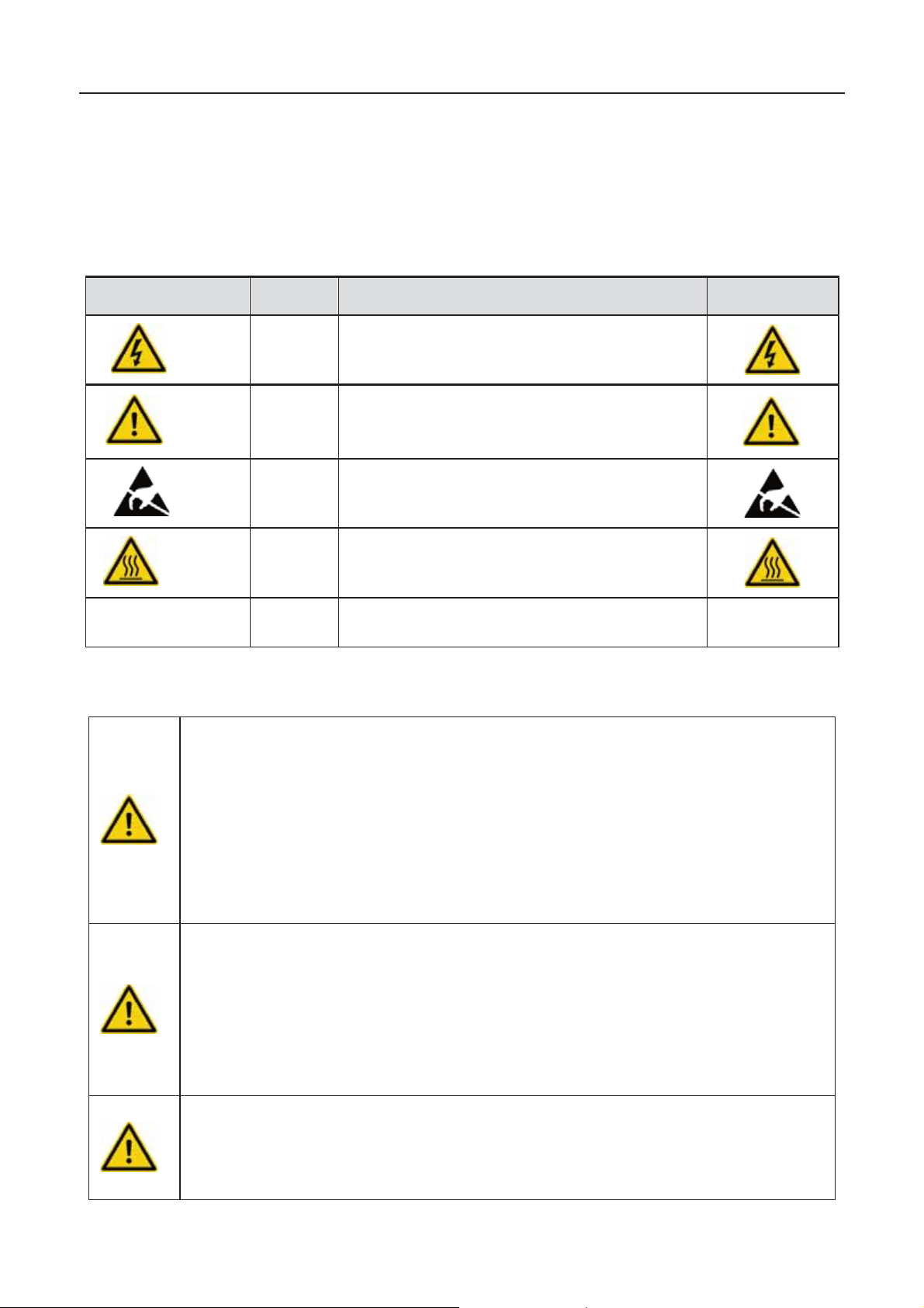
1.1 Icons
This manual provides relevant information with icons to highlight the physical and property safety
of the user to avoid device damage and physical injury.
The icons used in this manual are listed below:
Icons N
Hot
Note
1.2 Safety guidelines
z
Instruction
Note
or to the inverter. If there is something suspected, contact the shipping
company and l oc al dealer b ef or e ins tallin g.
z Only qu alified el ec t ric i ans are allow ed t o op erate on the inver t er.
z Do not
power supply is applied.
z This product can cause a residual current in the external protective earth
conductor. Where a residual current(RCM) device is strongly recommend to be used for protection in a case of
direct or indir ect c ont ac t, on l y an RCD or RCM of Type B is allow ed on the
supply side of this product.
z Ensur e th at th er e is n o el ectromag netic interference fr om
electr on ic eq uipmen ts on th e inst al lation site.
z Do not ref it th e i n verter unauthor i z ed.
6
Page 9
iMars grid-tied solar inverters Sa fe ty precaution s
especially
ponents inside the inverter are electrostatic. Take measurements to avoid
th at DC an d AC side circ uit br eak ers h ave been dis conn ec t ed and w ait
Note:
maintenance, troubleshooting and replacement
inverters
precautions.
Operators need to be familiar with the relevant safety regulations for electrical systems.
Operators need to be fully familiar with the composition and operating principle of the
eep the package and unit complete, dry and clean during storage and delivery.
lease r em o ve an d ins tall t h e inv erter with two or more peopl e, b ec ause of the
normal
echanical
z All the el ectric ins t allation needs to be c ompliance wit h th e nat ional or loc al
laws an d st and ar ds .
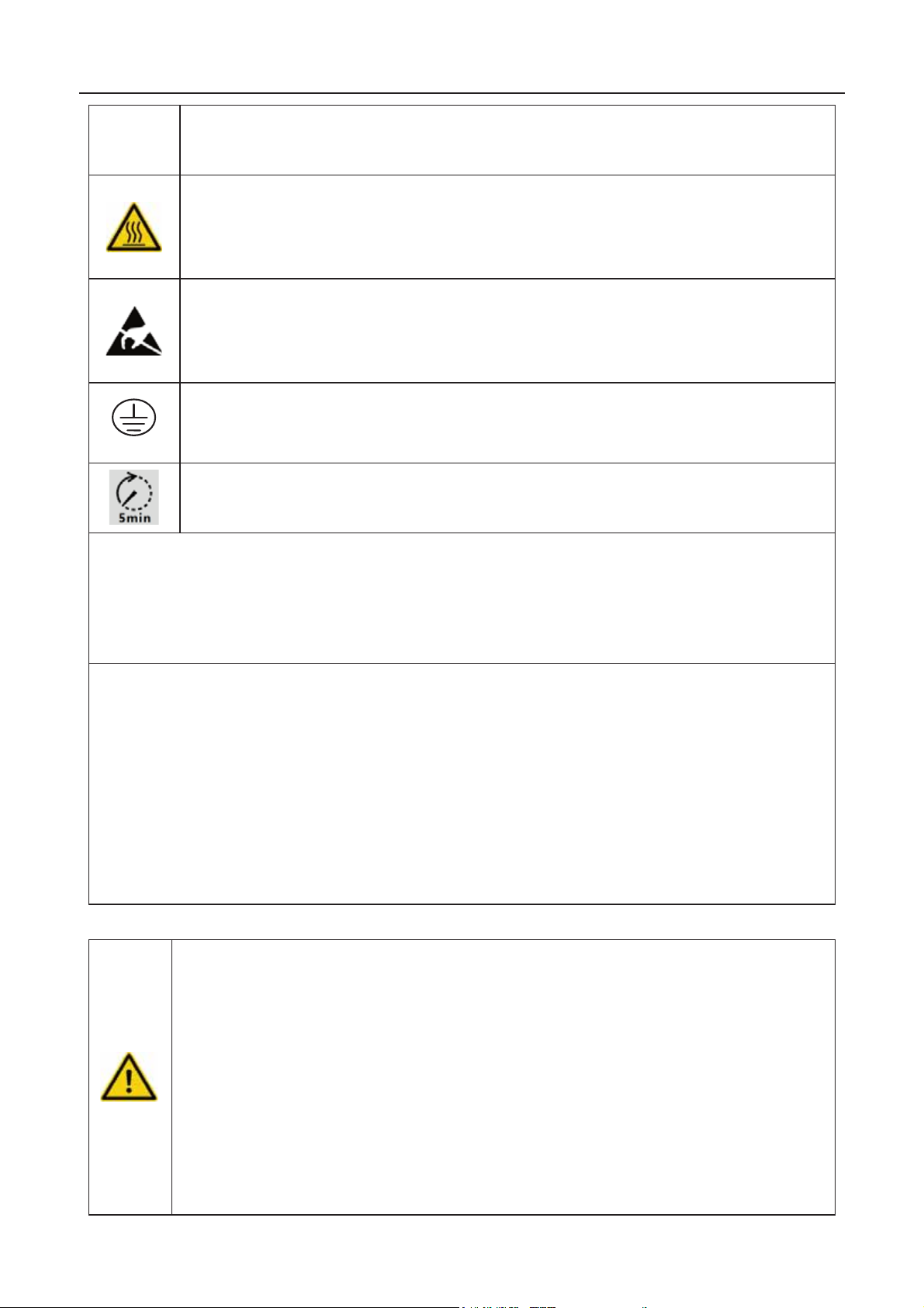
z The tem p eratur e of ind i vid ual parts o r t h e enc l os ure of the in verter–
the heat sin k m ay b ec ome hot in normal operat i on. Th er e is a dan ger of
burning. Do not touch.
z Do not open the cover of inver t ers unau thori z ed. The electric al par ts an d
com
electrostatic discharge during relevant operation.
z The inverter must be reliably grounded.
z Ensure
at least 5 minutes before wiring and checking.
Tec hni ca l pers onn el who ca n perform instal lati on, wiring, co mmi ss ion ing ,
of the iMars series grid-tied solar
must meet the following requirements:
z Operators need professional training.
z Operators must read this manual completely and master the related safety
z
z
entire grid-tied photovoltaic power generation system and related standards of the
countries/regions in which the project is located.
z Oper at or s mus t w ear p er sonal protecti ve eq uipm ent .
1.2.1 Delivery and installation
z K
z P
invert er is hea vy.
z Remove and install the inverter with appropriate tools to ensure safe and
oper ati on an d av oi d physical injury or deat h. The people also need m
protective measures, such as protective shoes and work clothes.
z Only qu alif ied elec tr ic i ans are allow ed to inst all th e in ver t er.
z Do not put and inst all t h e in verter on or c lose to c ombusti ble mater i al s .
7
Page 10
iMars grid-tied solar inverters Sa fe ty precaution s
rounded, otherwise
, other wise, im pr oper con nection or
enerator cells are exposed to light (even if it is dim), the
ection,
during
ait f or at le ast 5 minutes
z Keep the installation site away from children and other public places.
z Remo ve th e metal jew el ry such as ri ng and bracel et b ef or e ins t allation and
electrical connection to avoid electric shock.
z Do cover solar modules with light-tight materials. Exposed to sunlight, so lar
modules wil l out put dang er ous v olt age.
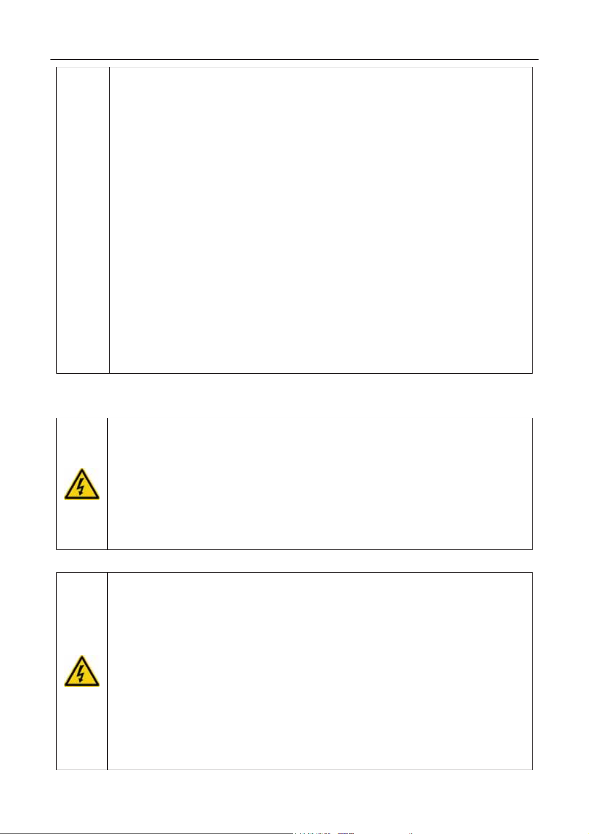
z The in vert er in put voltage d oes not e xc eed t h e m aximum in put voltage ;
otherwise inverter damage may occur.
z The positive and negative po le of solar modules can not be g
irrecoverable damage may occur.
z Ensur e the prop er groundi ng of the inverter
no grou nd ing may c ause stop of the inverter.
z Ensure reliable installation and electrical connection.
z When the pho tovoltaic g
generator supplies DC voltage to the inverter.
Note: iMars series grid-tied solar inverters are only for crystalline silicon solar modules.
1.2.2 Grid-tied operation
z Only qualified electricians are allowed to operate the inverter under the
permission of loc al power departments.
z All electrical connections must meet the electrical standards of the
countries/regions in which the project is located.
z Ensur e reliabl e ins tallation and el ec t rical c onn ec ti on befor e op eration.
z Do not open t h e cov er of inver t er d uri ng operat i on or vol t age is pres ent .
1.2.3 Maintenance and inspection
z Only qualified electricians are allowed to perform the maintenance, insp
and components replacement of the inverter.
z Contac t w ith th e l oc al d eal er or su pplier for maint en ance.
z In order t o avoi d irr el ev an t per sonn el fr om enterin g the m aint enanc e area
maintenanc e, temporary warning labels must be placed to warn
non-pr ofessi on als to enter or us ef ence f or isolation .
z Firstl y di s connect all pow er s upplies of t h e gr id t o th e in verter b ef or e any
maint en ance, an d then disconn ec t th e br eak ers and w
until th e in ver t er is d is c h arged b efore maintenance.
8
Page 11
iMars grid-tied solar inverters Sa fe ty precaution s
lease do
Do not dis pose of the in verter t ogether w ith hous ehold w aste. Th e user h as the
to the designated organization for recycling
z Please follow electrostatic protection norms and take correct protective
measures because of the electrostatic sensitive circuits and devices in the
inverter.
z Do not us e par ts and compon ents not pr ovided b y our c om p any duri n g
maintenance.
z Rest art the in vert er after s ett li ng the fault an d problem wh ic h m ay affect the
saf ety an d p erform ance of the in verter.
z Do not get close to or touch an y m etal c onduc tive part of th e gr id or inverter,
other wise el ectric sh oc k, ph ys ical inj ury or deat h an d fire may occ u r. P
not ign ore the warn ing icons an d ins t ruc t ions wi th “electric shock”.
1.2.4 What to do after scrapping
z
respo n sib i lity and ob li ga tio n to send i t
and disposal.
9
Page 12

iMars grid-tied solar inverters Product overview
2 Product overview
This ch apt er mai nl y d esc ri bes the app earance, pac k aging access ori e s , nam eplate, t ech nical
parameters and other information of iMars series grid-tied solar inverters.
10
Page 13
iMars grid-tied solar inverters Product overview
wit h IE C617 30 Class A rati ng .
2.1 Solar grid-tied power generation system
2.1.1 Applic ation
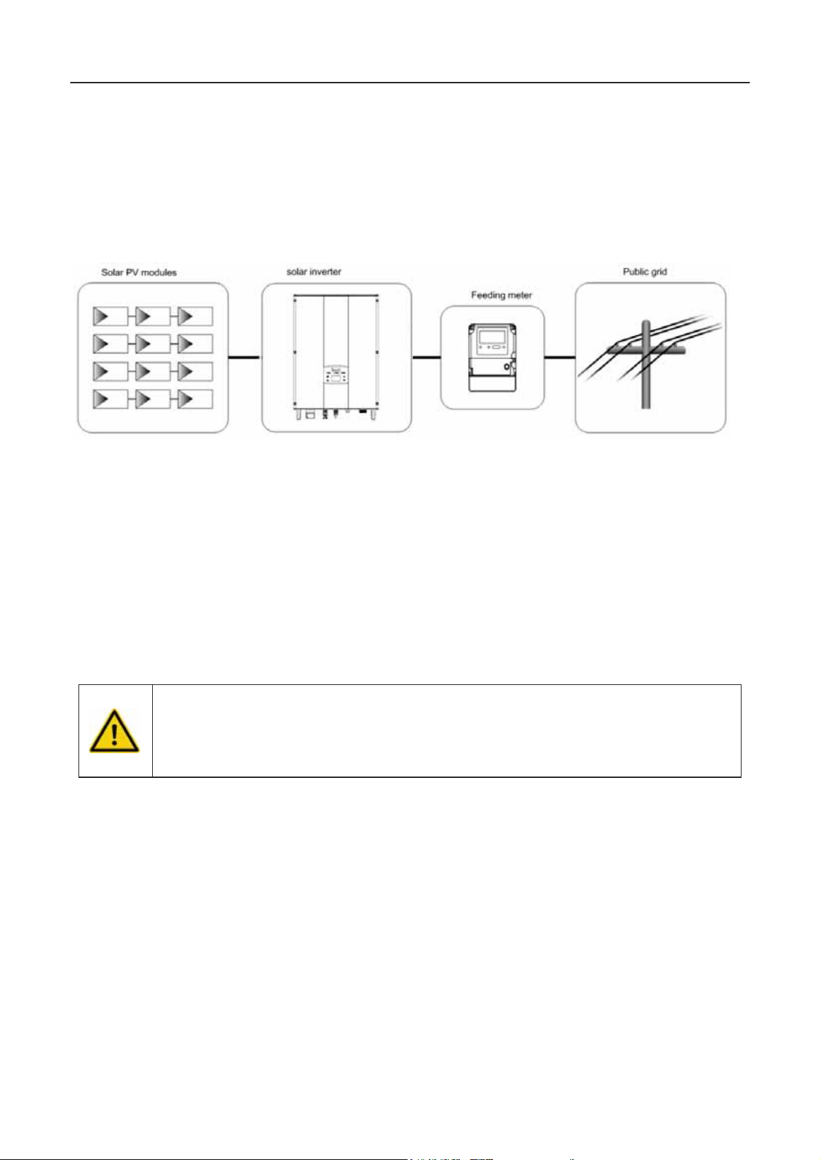
The photovoltaic grid-tied power generation system consists of solar modules, grid-tied inverter,
metering devices and public grid.
Figure 2.1 Application o f iMars series grid-tied solar inverters
Grid-tied solar inverter is the core of photovoltaic power generation system. The solar energy can
be converted into DC electric energy through solar modules and then be changed into sinusoidal
AC energy which has the same frequency and phase with the public grid by grid-tied solar
inverters, and then be fed to the grid.
iMa rs series grid-tie d solar inverters are only applied in solar grid-tied power generation system
and its DC input are only composed of crystalline silicon solar modules whose negative and
posit i ve p ol es are not gr oun ded.
z The re comme nded sola r modules need to comply
z iMars series grid-tied solar inverters are only for crystalline silicon solar
modules.
2.1.2 Supported grid connection structure
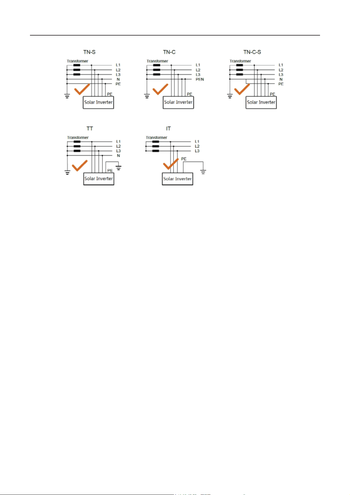
iMars series grid-tied solar inverters support TN-S, TN-C, TN-C-S , TT and IT grid connection.
When applied to the TT connection, the N-to-PE voltage should be less than 30V.
11
Page 14
iMars grid-tied solar inverters Product overview
Figure 2.2Type of grid
12
Page 15
iMars grid-tied solar inverters Product overview
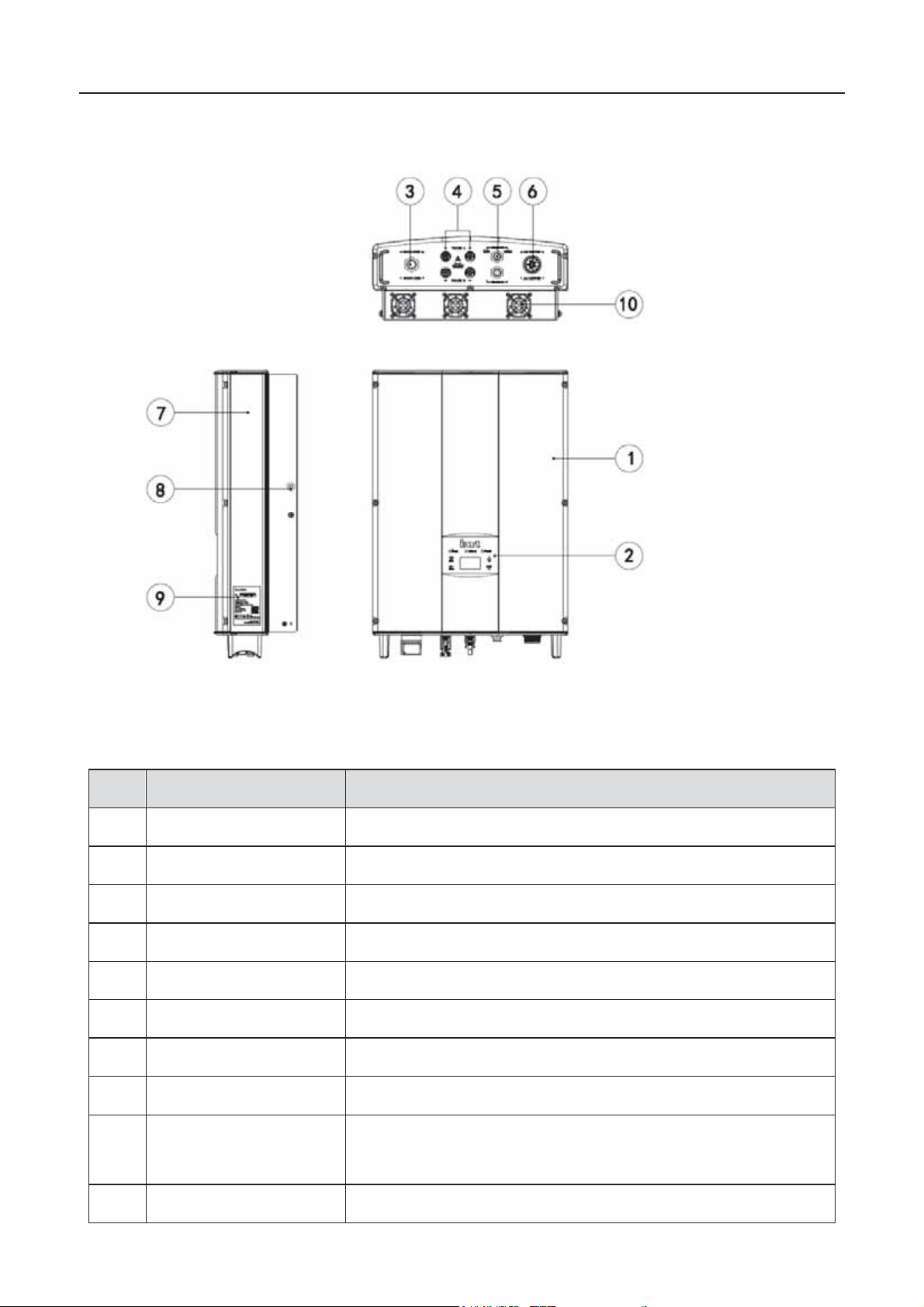
No.
1
C
over
2
O
pe rational panel
L
3
Communication port
DRM
4
DC input port
F
5
Communication port
RS485 and EXT communication port
6
AC terminal
F
7
Cooling chamber
8
R
adiator
9
N
ame plat e
F
of the inverter
10
FAN
BG6KTR
2.2 Products appearance
Table 2- 1 Parts inst r uc t i on
Name Instruction
Figure 2.3 Products appearance
CD indicators
Communi cation port
or the conn ec tion of sol ar m odu l es
or the conn ec tion of AC output
or rated parameters an d s af ety precau t i ons
(NO FAN) , BG8KTR / BG10KTR(Air cooling)
13
Page 16
iMars grid-tied solar inverters Product overview
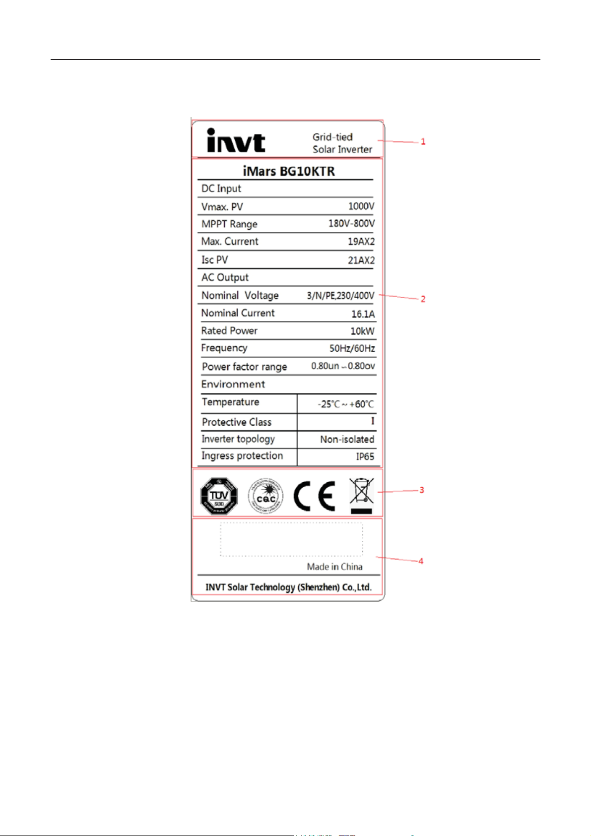
2.3 Nameplate
Figure 2.4 Inverter nameplate
˄1˅Tradem ar k and pr oduc t type
˄2˅Mod el an d im port ant t ech nical p aram eters
˄3˅Certification system of the inverter confirming
˄4˅Serial number, company name and country of origin
14
Page 17
iMars grid-tied solar inverters Product overview
Instruction
No.
Mode
Requirement
1
DRM0
Operter the di sconnectio n devise
2
DRM1
Do not consume power
3
DRM2
Do not consume at more than 50% of rated power
4
DRM3
Do not consume at more than 75% of rated power AND Source reactive
power if capable
5
DRM4
Increase power consumption(subject to constraints from other active DRMs)
6
DRM5
Do not generate power
7
DRM6
Do not genera te at more than 50% of rated power
8
DRM7
Do not generate at more than 75% of rated power AND Sink reactive power if
capable
9
DRM8
Incr eas e power g enerat i on( s ub j ect to const r aints from oth er active DRMs )
Icons
z TUV certification mark. The inverter is certified by TUV.
z CE certification mark. The inverter complies with the CE directive.
z CQC certification mark. The inverter is certified by CQC
z EU WEEE mark. Cannot dispos e of the inverter as household wast e.
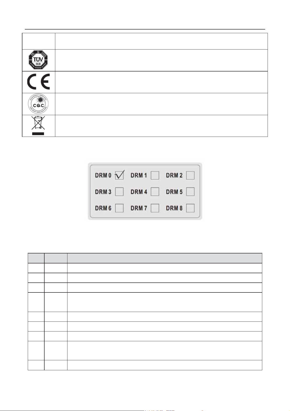
2.4 DRM instruction
Table 2-2 DRMs instruction
Figure 2.5 DRM label
Note: Our product only realize the DRM0 function
15
Page 18
iMars grid-tied solar inverters Product overview
Rated output power
Three
tied solar inverter
tied solar inverter
tied solar inverter
2.5 Products modules
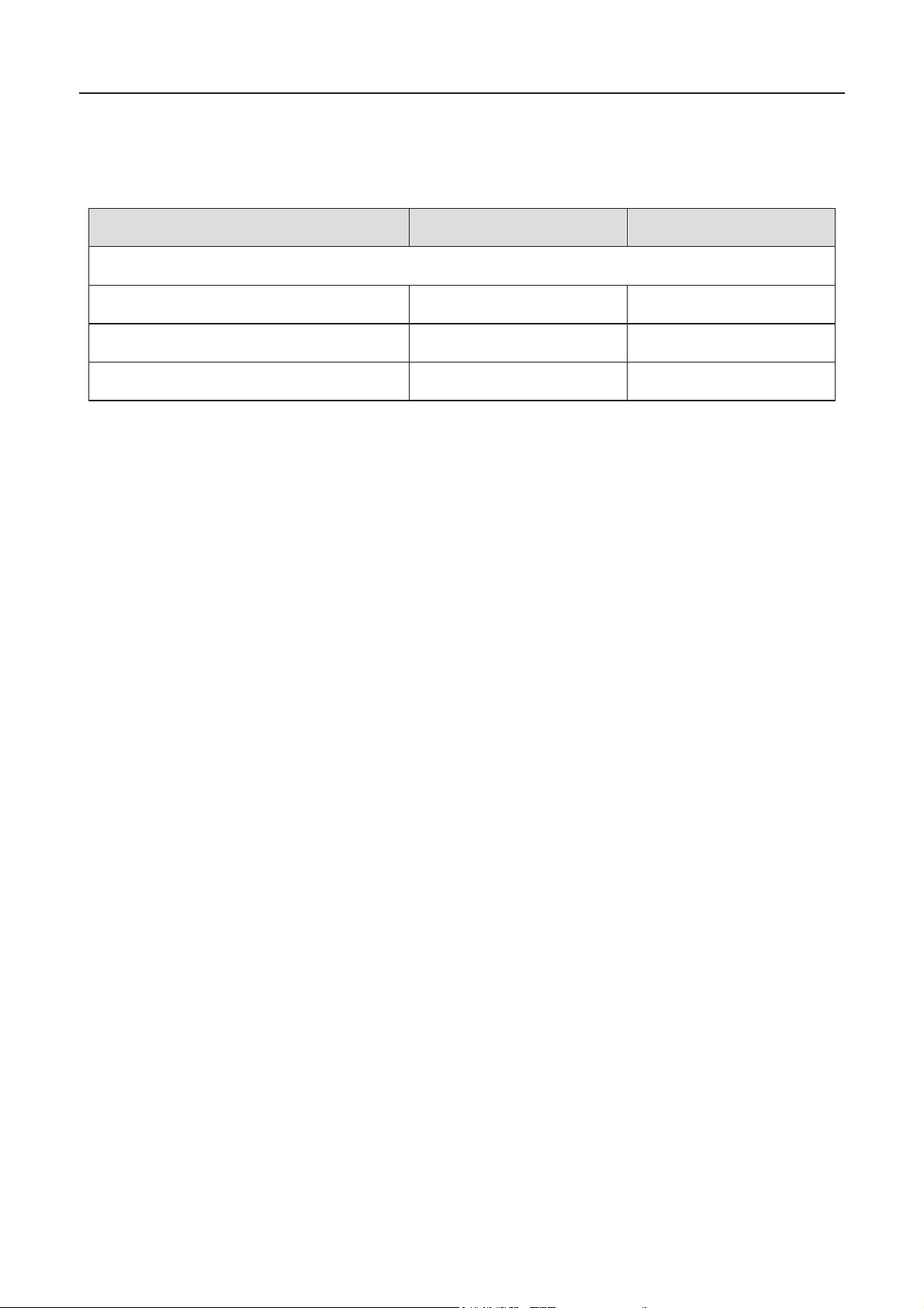
Table 2-3 Models of iMars grid-tied solar inv erter
Product na me Model
-pha se ( L1,L 2,L 3,N,PE )
Thr ee- ph as e gr i dThr ee- ph as e gr i dThr ee- ph as e gr i d-
Note: Refer to the product specifications in chapter 10 for detailed information.
BG6KTR
BG8KTR
BG10KTR
6000
8000
10000
16
Page 19
iMars grid-tied solar inverters Product overview
(mm)
(mm)
D
(mm)
et weight
(kg)
(mm)
(mm)
(mm)
Gross
weight (kg)
Packaging
Material
630
470
284
22
Paper
BG8KTR / BG10KTR
675
470
284
Paper
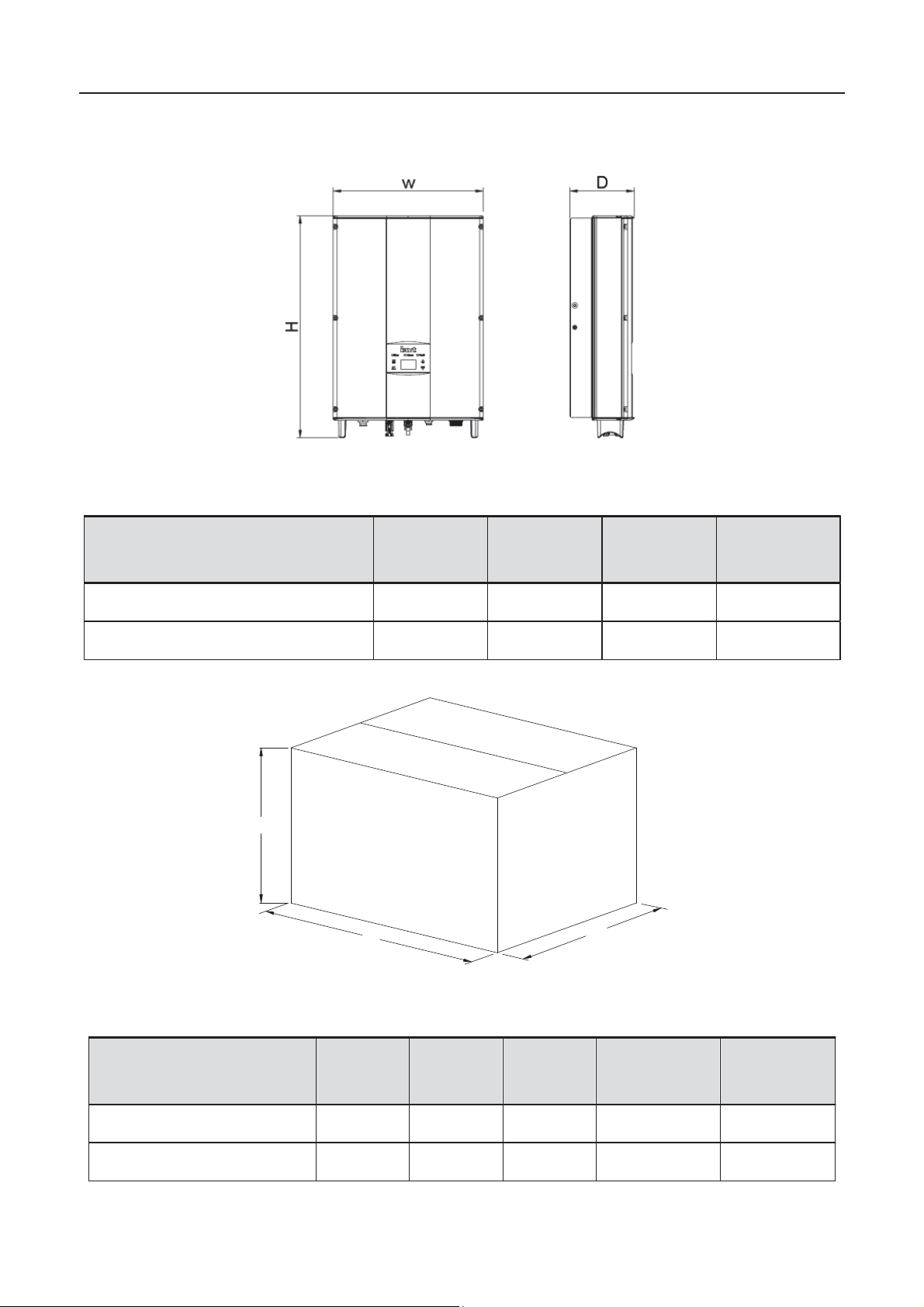
2.6 Dimensions and weight
Figure 2.6 Inverter dimensions
Table 2-4 Inverter dimension an d net weight
H
Model
BG6KTR 530 360 150 20
BG8KTR / BG10KTR 575 360 150 23
W
N
D
H
W
Figur e 2. 6Paper pack ag es di m ens ion
Table 2- 4 Packag es di m ens i on and gross w eig ht
Model
BG6KTR
H
W
D
25
17
Page 20

iMars grid-tied solar inverters Storage
3 Storage
If th e invert er is not p ut into us e immedi ately, the st orage of i nverter s hould m eet the f ollowin g
requirements:
z Do not remove the outer packing.
z The inverter needs to be stored in a clean and dry place, and prevent the erosion of dust and
water vapor.
z The st orag e t emp erat ure s hou ld b e kep t at -4 0°C~ +70° C, and th e r elat ive hu midit y s h ould
be kept at 5%RH ~ 95%RH .
z The st ac ki ng of inver t er s is rec ommen d ed to be placed accord in g to th e nu mb er of st ac k in g
layers in th e origi n al sh ip m ent. Pl ac e the inverter c arefully duri ng st a c king to av oid personal
injur y or equ ipment dam age caused b y the f alli ng of equipment.
z Keep away from chemically corrosive substances that may corrode the inverter.
z Periodic inspections are required. If damages are found by worms and rats, or packaging
are found to be damaged, the packaging materials must be replaced in time.
After long-t erm st orage, i nvert ers need to be ins pect ed and t ested b y qualifi ed pers onnel bef ore
put into use.
18
Page 21

iMars grid-tied solar inverters Installation
4 Installation
This chapter describes how to install the inverter and connect it to the grid-tied solar system
(including the conne ction between solar mo dules, pub lic grid and inverter).
Read this ch apter carefu ll y and ens ure all install at i on requirem ents are met befor e ins tallation.
Only qu alified el ec t ric i ans are allow ed to ins tall th e in verter.
19
Page 22
iMars grid-tied solar inverters Installation
No.
1
BG6KTR / BG8KTR / BG10KTR inverter
2
3
4
5
4
6
2 pairs
7
1
No.
Mark the installation hole
Drill in t h e brac k et or wall
Hamm er on t h e exp ansi on b olts
Fix the ins t allation br ac k et
Fasten the screws, remove and install AC wiring box
4.1 Unpacking inspection
Insp ect th e informat i on of the order and t h e nam e pl ate to ensure th e prod uc t are the ord er ed on e
and no damage to the package. If any problem, contact the supplier as soon as possible.
Put the invert er int o t h e pac k ag e if not used and pr otec t it f r om humid ity and dus t.
Check as f ollowin g aft er un p ac kin g:
(1) Ensure no damage to the inverte r unit.
(2) Ensure the operat ion manual, port and installation accessorie s in the package.
(3) Ensure no damage or loss to the ite ms in the package.
(4) Ensure th e inf or m ati on of the ord er ar e th e sam e as that of th e n am e plate.
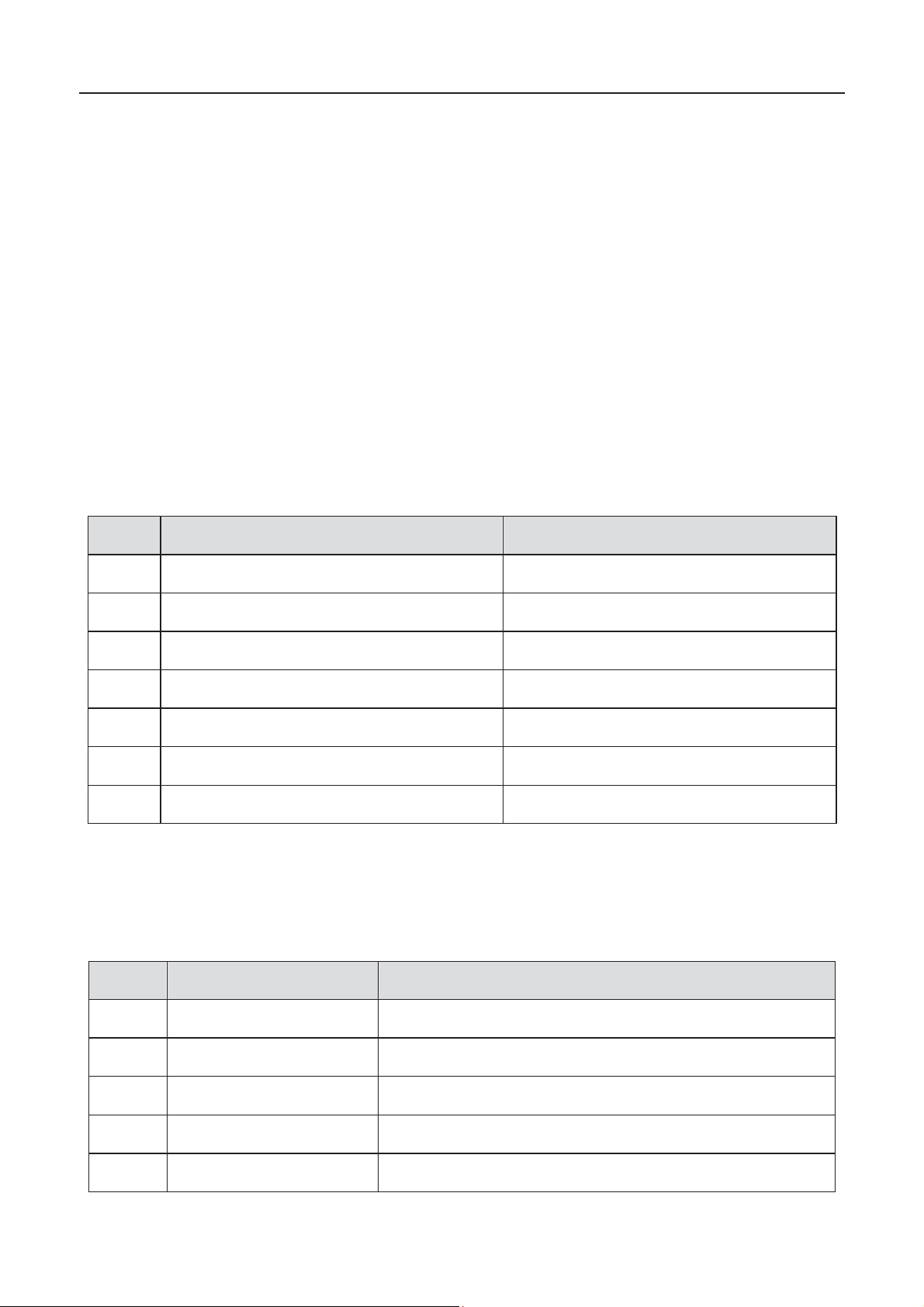
Packinglist:
Table 4-1 Detailed delivery list of three-phase inverter
Name Quantity
Installation bracket 1
oper ati on m anual
Hexagon ass embling bolts M5*20
Expansion bolts M6*60
DC connector
AC co nnector
4.2 Before installatio n
4.2.1 Installation tools
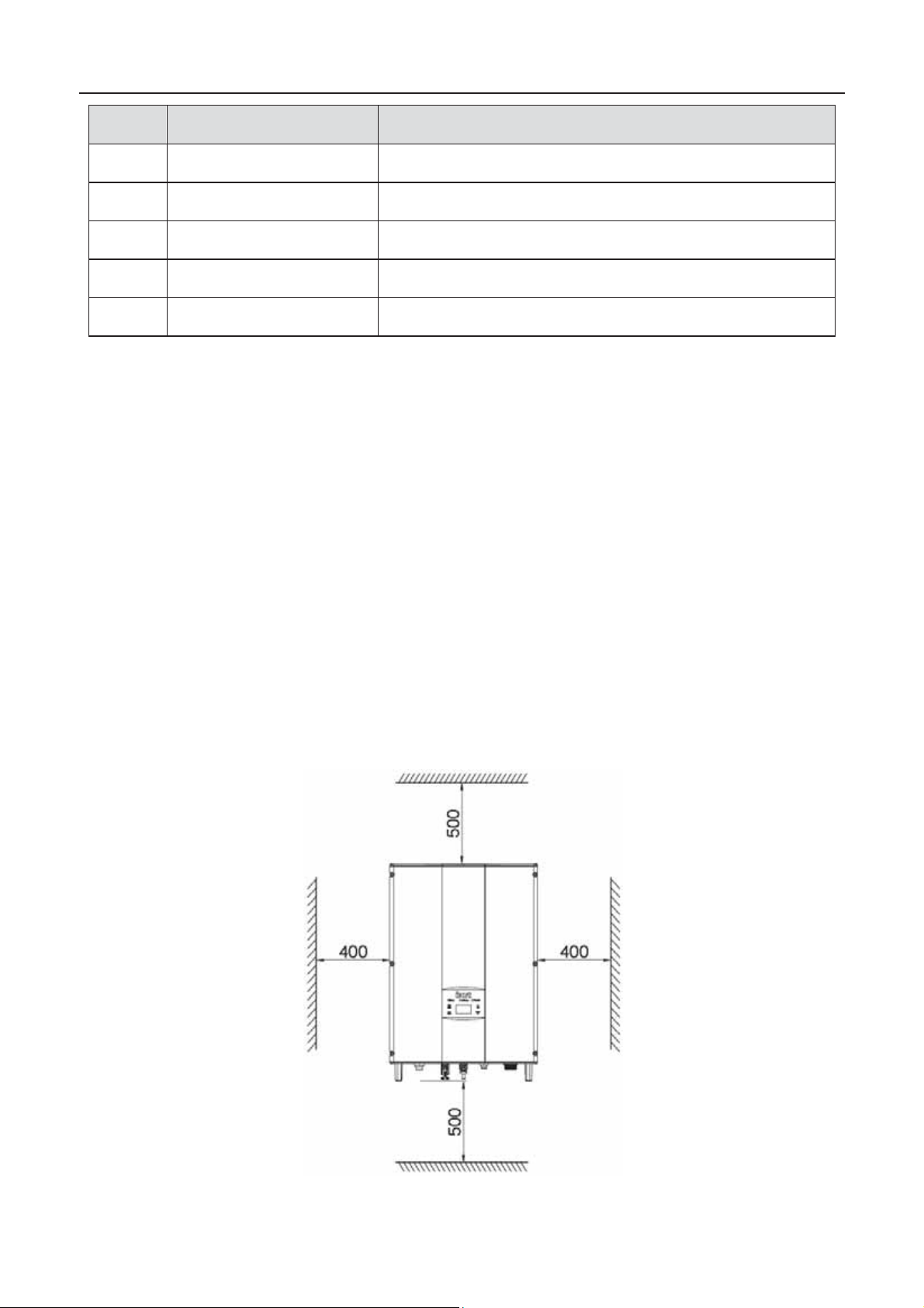
Table 4-2 Tools list
Installation tools
1
1
2
Instruction
1
2
3
4
5
Marking pen
Electrodrill
Hammer
Monke y wr enc h
Allen driver
20
Page 23
iMars grid-tied solar inverters Installation
No.
Straight screwdriver
For AC wiring
Measuring insulation
Check the circuit and AC and DC voltage
Weld communications cable
10
Crimp DC terminals
Installation tools
6
7
8
9
Megger
Multimeter
Electric iron
Wire c rimper
Instruction
perform ance and im p ed ance
4.2.2 Installation place
Select installation place based on the following considerations:
(1) Height from ground level should be enough to ensure that display and status LCD are
easy to read.
(2) S elec t a well v entilated plac e sh elter ed fr om di rect sun radiation and rain.
(3) Allow sufficient space around the inverter to enable easy installation and removal from the
mounting surface. Refer to Figure 4.1.
(4) The envir on m ent temperatu r e is between - 25 ć~60ć.
(5) The ins tallat i on p os ition keeps awa y from th e int erface of ot h er electr i c al de vise.
(6) The invert er n eeds t o b e inst al led on a fir m an d sturdy surfac e, suc h as w al l an d m etal
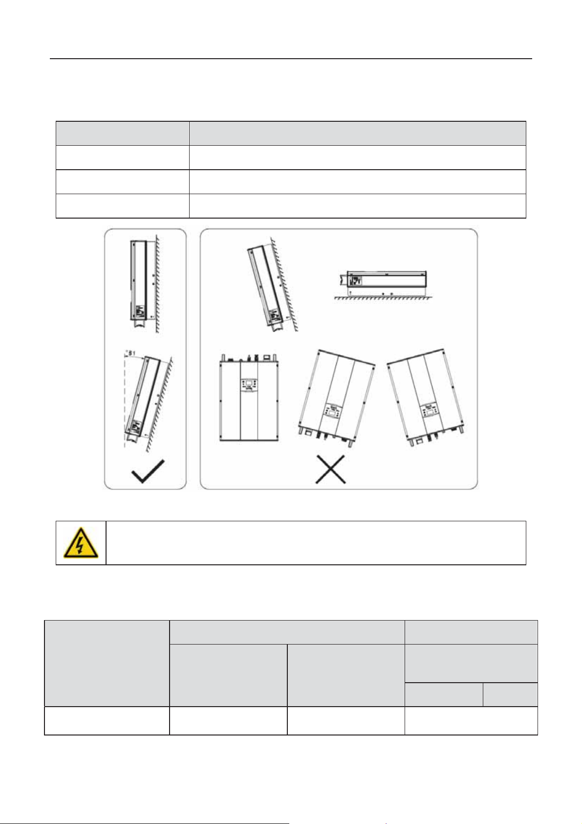
brack et and s o on.
(7) The installation surface should be perpendicular to the horizontal line. Refer to Figure 4.2.
(8) The installation should be ensure that the inverter is reliably grounded, and the material of
grounded metal conductor should be consistent with the metal material reserved for the
groun di ng of the in vert er.
Figure 4.1 Installation space
21
Page 24
iMars grid-tied solar inverters Installation
otherwise
DC side
AC side
section
(length ≤50m)
mm
ϡ
section
(length >50m ) mmϡ
Mini cross-section
mmϡϡ
L
N/PE
BG6KTR / BG8KTR /
BG10KTR
Ensure there is sufficient space for heat-releasing. In generally, below space requirement should
be met:
Table 4-3 Detailed installation space
Minimum clearance
Lateral
Top
Bottom
400mm
500mm
500mm
Figure 4.2 Installation position
z D o not remo ve any part and c omponent of the i nverter u ninten ded;
damage to the device and physical injury may occur.
4.2.3 Connection cables
The user can select connection cable according the table below:
Table 4-4 Cable specifications
Model
Cross-
Cross-
ϡ
4 4 4
22
Page 25
iMars grid-tied solar inverters Installation
z In order to protect the PCE, user and installer, external DC and AC circuit
break er sh all be equi pp ed at th e end -us e appl ication ;
z The wiring shall be according local electric code. Choose proper cable for power
input and output lines. Input and output cable shall be PV priv a te cable s sui ta ble
for outd oor use.
DC input
AC output
Recommended DC
breakers (optional for
length >100m)
BG6KTR / BG8KTR
DC1000V, C16A, 2P
AC400V, C16A, 4P
BG10KTR
DC1000V, C16A, 2P
AC400V, C25A, 4P
4.2.4 Miniature circuit breakers
It is recom mend ed stron gly t o ins tall c ircuit break ers or f us es at t he DC input and AC out put to
ensur e s af e install ation and r un ni ng.
Table 4-5 Breaker specifications
Model
Recommended AC
breakers
4.3 Mechanical installation
Sinc e the ins tall ation place c an b e made by diff erent c onstruc tion mater ials, t he inv erter c an be
inst all ed b y d if f er ent m ou nting m ethods . Take th e t ypical ins t all ation envir on m ent as the ex am ple,
the m anu al d esc r i b es h ow t o ins tall t h e in verter on c oncrete w al l. The invert er sh ou ld be m oun ted
in a vertical pos it i on of 90°t o the h or iz on t al line as sh ow n in Figure 4. 2.
4.3.1 Installation of three-phase inverter
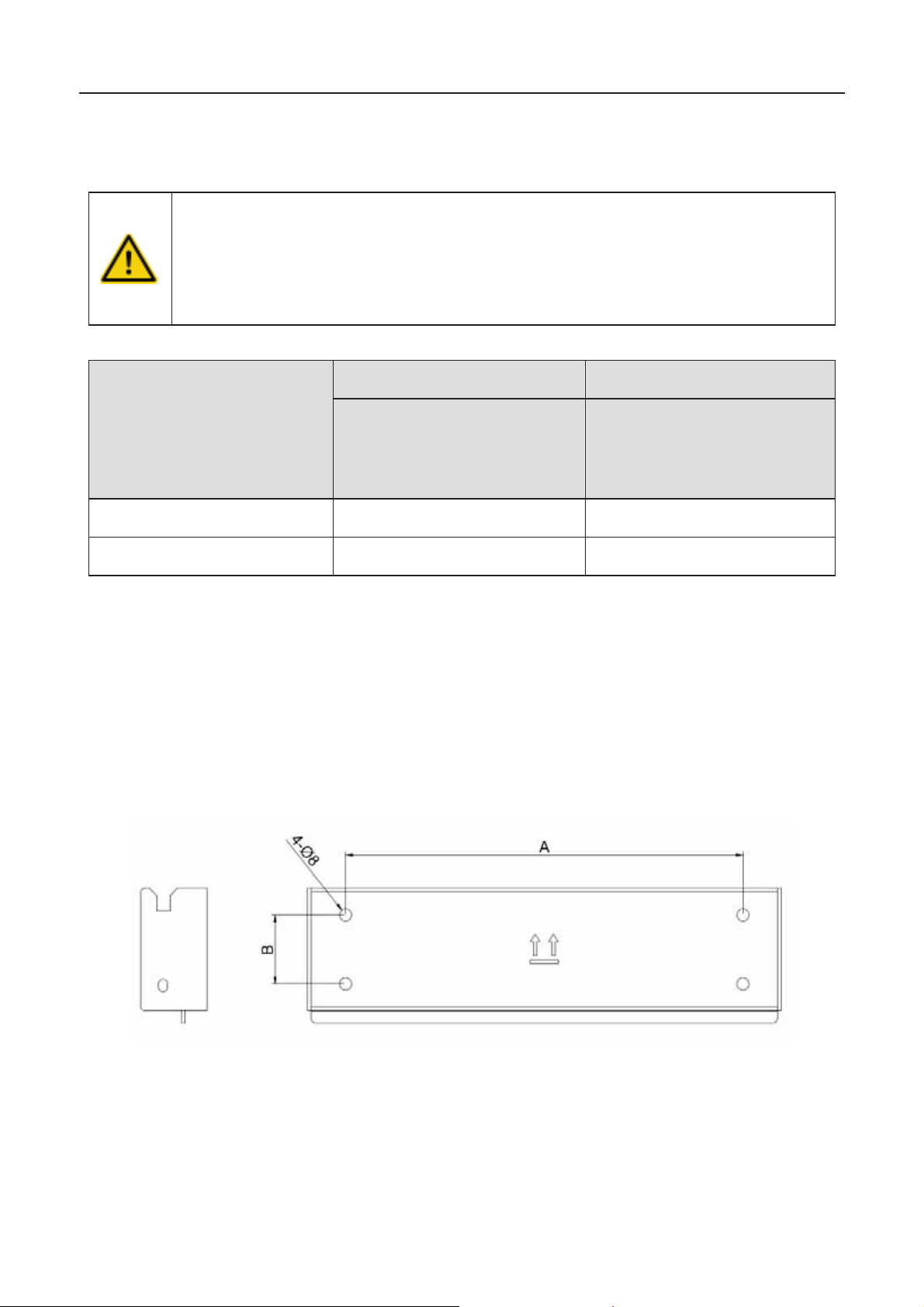
Figure 4.3 Installation bracket of 6~10kW inverter
23
Page 26
iMars grid-tied solar inverters Installation
Instal l ation hole
A(mm)*B(mm)
BG6KTR /BG8KTR/ BG10KTR
260*45
No.
Table 4- 6 Size of install ation br ac k et
Model
Table 4-7Instruction of installation bracket
Structure in st ructio n
1
2
Installation steps:
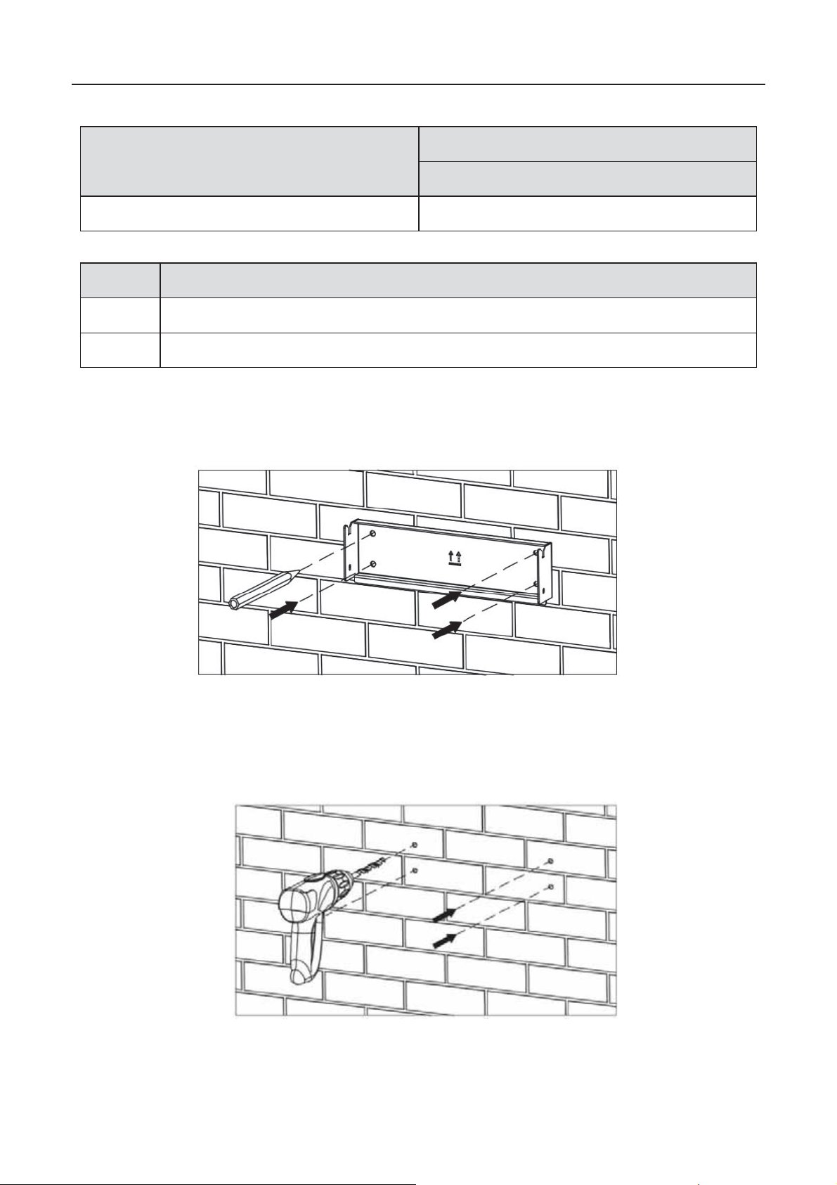
(1) Put th e m ounting pl ate on the w all to determin e t h e punc h pos it i o n . As show n in Figure 4. 4.
Level th e hol es with a level ru l er and mark it with a m ar k ing pen .
Hexagon ass embling bolt hole M5
Installation holeΦ8
Figure 4.4 Determine the punch posi tion
(2)Drill 4installation holes on the wall with electric drill. As shown in Figure 4.5.
Figure 4.5 Drilling
24
Page 27
iMars grid-tied solar inverters Installation
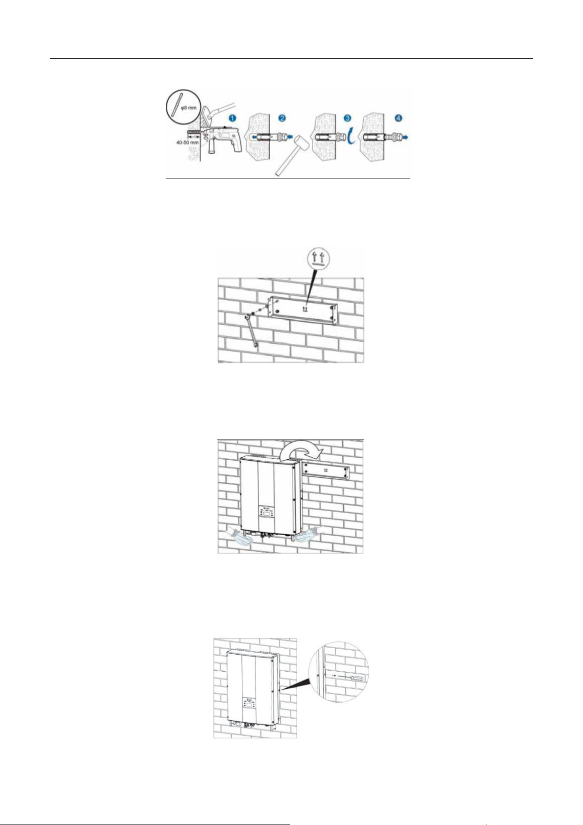
(3) Fix the expansion bolts to the installation holes with hammer, as shown in Figure 4.6.
Figure 4.6 Install expansion bolts
(4)Fix t h e ins t all at i on br ac k et on to the expansi on b olts and ensure the ins tallation is fir m
enough(tightening torque 8.5NЬm). As shown in Figure4.7.
Figure 4.7 Fix the installation bracket
(5) Hang the inverter onto the installation bracket and ensure the installation is firm enough.
As shown in Figu re4.8.
Figure 4.8 Installation of inverter
(6) Ensure the inverter is installed properly and tighten the M5X20 bolts into the screw holes on the
left and right side of inverter. As shown in Figure 4.9.
Figure 4.9 Tighten M5X20 bolts
25
Page 28
iMars grid-tied solar inverters Installation
Impr oper oper ation dur ing th e wirin g proc ess can c aus e fatal in jury t o oper at or
or unrecoverable damage to the inverter. Only qualified pers onnel can perf orm
with local and national
All cables must be firmly attached, undamaged, properly insulated and
It is not allowed to close the AC and DC breakers before the inverter is
ote
the instructions provided in this section while observing all
Always note the rated voltage and current defined in this manual. Never exceed
4.4 Electrical installation
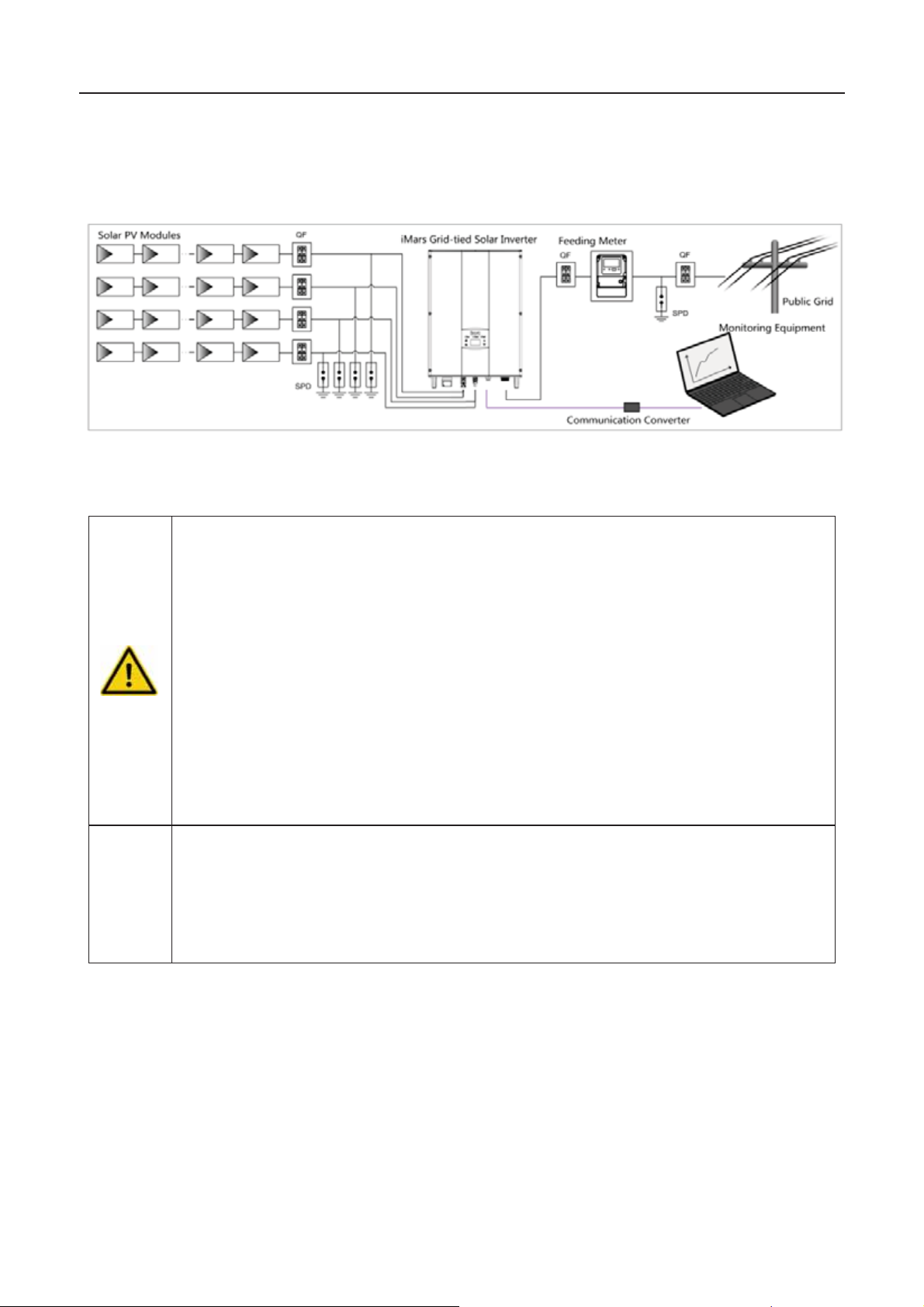
This sect i on propos es t o desc ribe detail ed electrical instal lation an d r el ated saf et y inst r uc t i ons .
Figure 4.10 B lock diagram of the grid-tied solar system
N
z
the wiring work.
z All electrical installations must be in accordance
electrical codes.
z
adequately dimensioned.
z
electrically connected.
z Read and follow
saf ety warnings.
z
the limits.
26
Page 29
iMars grid-tied solar inverters Installation
local electrical safety laws and regulations are
4.4.1 Connection of solar modules
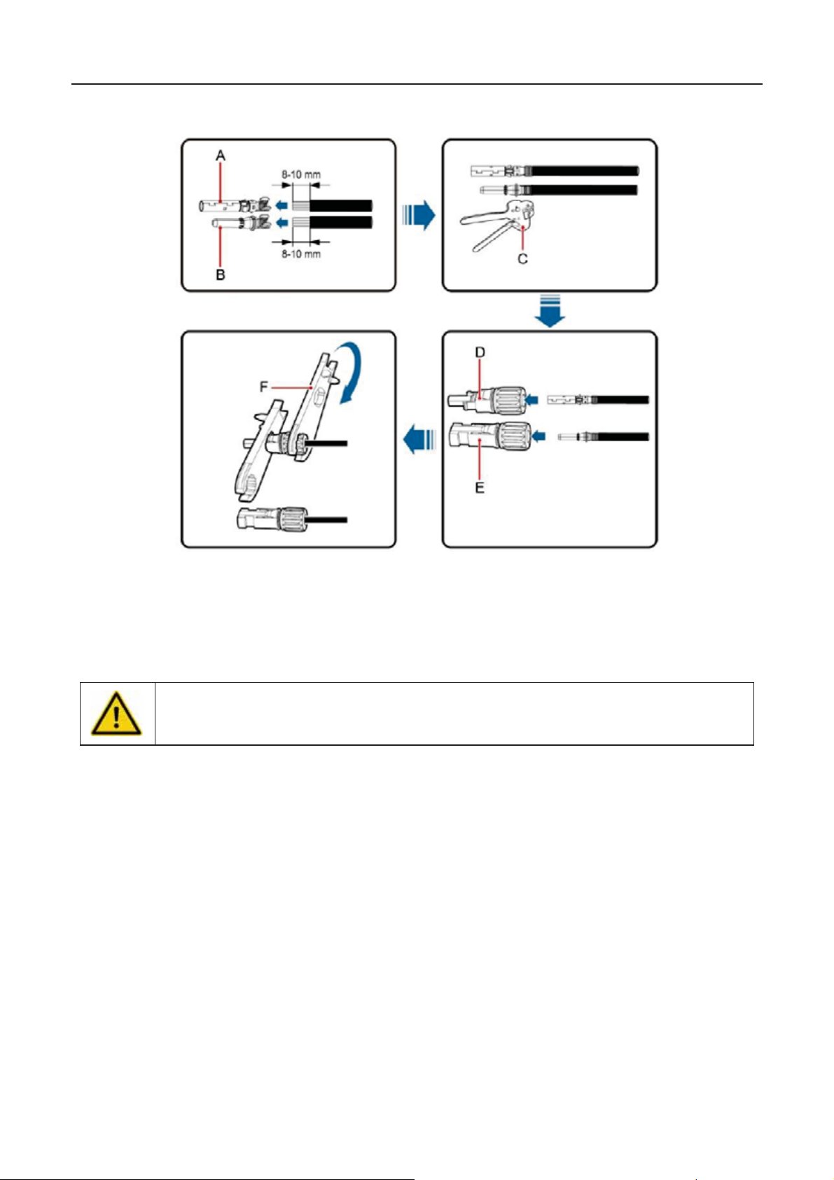
Figure 4.11 Connection between DC connector and solar modules
Connection steps:
(1) Light i n g, sh or t- circ uit and other prot ec tion m eas u res whic h meet the loc al el ec trical s af et y
laws and regulations are needed before the AC connection.
z O nly qual ified c ables un der th e
allowed to connect.
(2) Conn ect the out put cabl es of sol ar modul es to the DC conn ect or as f igure 4. 11 s hows.
Remo ve the is olati on layer of th e DC c able f or about 8- 10mm. Insert the c onduct or part
into t h e appr op riate positi on of the conn ect or, c ri mp the MC4 DC termi n al and t ighten th e
nut with a torque of 2.5-3Nm. The wiring of negative pole is the same as that of the
positive pole. Ensure the poles of solar modules are well connected with the connectors;
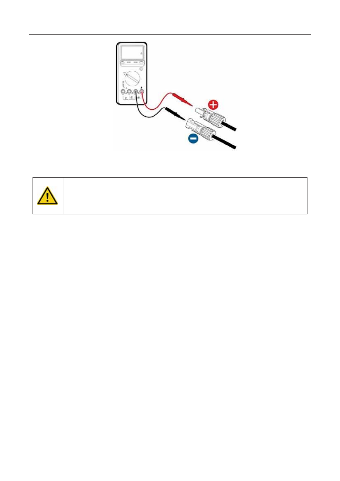
(3 ) Aft er t he D C con n ect or is c on n ect ed , us e a mul t im et er t o m eas u re t h e vo lt ag e of th e DC
input str ing, ver ify the polar ity of the DC inp ut cabl e, and ensur e that the voltag e of each
string is within the allowable range of the inverter, as shown in Figure 4.12.
27
Page 30
iMars grid-tied solar inverters Installation
he solar modules connected with the inverter needs to be the configured ones
therwise, device
damage, unstable op erati on or f ir e may occ ur.
Figure4.12 DC input voltage meas uring
z T
other than some connecting devices without authorized. O
(4) C onn ect the DC connect or wit h the in vert er and ensur e ti gh tly- fast ened.
(5) Inser t the screw-driver into the hole of the connector to remove the connector fo rm the
inverter.
(6) Unclench the pressed cover with screw-driver to remove the cables from the connector.
28
Page 31

iMars grid-tied solar inverters Installation
z Only qu alif ied c abl es un der t h e l oc al el ectr ic al s afet y law s and r egul ations are
allowed to connect.
z Only with the permission of the local electric
power company can the inverter be
connected to the utility grid.
4.4.2 AC connection
Figure 4.13 AC connection o f th ree-phase inverter
Connection steps of three -phase inv erter:
(1) Before connecting the three-phase AC grid cable to the inverter, take lightning and short circuit
protection measures in accordance with the local electrical safety codes;
(2) As shown in Figure 4.8, connect and fasten L1,L2,L3, N and PE conductors of the three-phase
comm on gri d to AC ter minal with 0.5N m t orque, ass emble t he t erminal tight en to 2.5 -3Nm, and
then connect the terminal to the AC port of the inverter.
(3) Fi x an d conn ect t he DC ou t p ut cabl es of P V board with the match ed D C connec tors , and then
connect the connectors to the DC port of the inverter.
29
Page 32

iMars grid-tied solar inverters Operation
5Operation
This chapter describes detailed operation of the inverter which involves the inspection before
oper ati on, gr id -tied op erati on, stoppin g an d daily mai ntenance of th e in ver t er.
30
Page 33
iMars grid-tied solar inverters Operation
o c heck as abov e before an y oper ation if the s ystem or inverter needs to be
installed, refitted and maintained.
Note
to
eep the in vert er pow er on at least 30 mi nut es t o charg e for th e inte rn al cloc k
battery.
Gr een ind icator bli n ks , oth ers off: th e inverter is p ow er on an d in s elf-ins p ec ti on ;
self
“Warn
P
mentioned, finally settle the problems as chapter 8.
, do as chapter 5
mentioned.
5.1 Inspection before operation
Check as follows before operation (including but not limited to):
(1) Ensure the installation site meet the requirement mentioned in section 4.2.2 for easy
installation, removing, operation and maintenance.
(2) E ns ur e t h e mec h anical ins t all ation m eet the req uir em en t m ent i on ed in s ect i on 4. 3.
(3) Ensure the electrical installation meet the requirement mentioned in section 4.4.
(4) E ns ur e all s w itc h es ar e “off”.
(5) E ns ur e t h e volt ag e m eet the req uiremen t m entioned in chapt er 1 0 .
(6) Ensure all el ec trical s af et y precau t i ons ar e cl e ar l y-identified on the ins t all ati on site.
z D
5.2 Grid-tied operation
z When power on the inverter for the first time, please refer to section 6.5
compl ete grid c ert if icati on ch oice.
z K
Please start the inverter as follows:
(1) E ns ur e t h e r equ irements ment i oned in section5.1 ar e m et.
(2) S wit c h on th e br eak ers at th e AC side .
(3) Switch on the integrated DC switch.
(4) Switch on the switch on the DC side.
(5) Observe the LED indicators and information displayed on the screen. Refer to chapter 6
for detai led information.
Run
Run
Green indicator on, others off: the inverter is in power generation after
-inspection----successful commissioning.
” or “Fault” indicat ors are on or bli nk in g: th e in ver t er is power on, but faul t occ ur s .
lease refer to section 6.3 for detailed information, and then stop as the section 5.3
If all faul ts are solv e d
31
Page 34
iMars grid-tied solar inverters Operation
Maintenance
contents
Maintenance
cycle
Store the
oper ati on data
Use real
-time monitoring software to read inverter
running data, regular ly back up all inverter running data
and
stats.
Chec k the moni torin g s oft w ar e an d in verter
LCD screen to make sure
the parameters are set
correctly.
Onc e each q u art er
Check inverter
operation
status
Check to make sure the inverter installa tion is solid, no
damage or defor m ation. When inverter running, check
to make sure th e sou nd and v ariabl es are norm al .
When inverter running, use thermal imager to check
whether the case cooling is normal.
Every six months
Clean th e
surface
Check th e amb ient humidity and dust ar ou nd in ver t er,
clean the inverter when necessary. See Section 5.4.2.
Every six months
Check
electrical
connection
Check the cable connection and inverter terminals
,
make sure they are connected reliably, not loose, and
no damage, insulation reliable.
Every six months
Che ck the
security
features
Che ck the off
-on feature of in ver ter: us e m onit or i n g
soft war e or LC D an d k eyb oard on th e in verter, do "off"
and "on" operation, to confirm its off
-
on feature intact. At
the same
time, make sure monito ring softwa re ca n
normally communicate with the
inverter. Check the
warning label on or around th e invert er, if necessary
replaced.
Every six months
5.3 Stopping
Stop th e inv er t er as f oll ows it n eeds m ainten ance, ins p ection an d tr o ubl es hooting:
(1) Switch off the breakers at the AC side.
(2) Switch off the integrated DC switch.
(3) Switch off the switch on the DC side.
(4) Wait at least 5 mi nutes until the inter n al part s an d c omp onents ar e dis c har g ed. And then
stop th e in verter.
5.4 Daily maintenance
The inv erter can perf orm power g eneration , s tart and stop au tomatic ally even th e day an d night
shif ts and seasons chan ge in one year. In or der to pr olong th e servic e life, d aily maint en anc e and
inspection are needed besides following the instructions mentioned in this manual seriously.
5.4.1 Regular maintenance
Maintenanc e met hod s
32
Page 35
iMars grid-tied solar inverters Operation
5.4.2 Maintenance guide
Clean the inverter
Cleani n g pr ocedur e is as f ollows:
(1) Disconnect the input and output switches.
(2) Wait ten minutes.
(3) Use a soft brush or a vacuum cleaner to clean the surface and the inlet and outlet of the
inverter.
(4) Repeat Section 5.1 operating content.
(5) Restart the inverter.
Fan clea ni n g (f or BG 8KTR and BG 1 0K T R )
The cleaning steps are as follows:
(1) Disconnect the input and output of inverter.
(2) Wait ten min ut es.
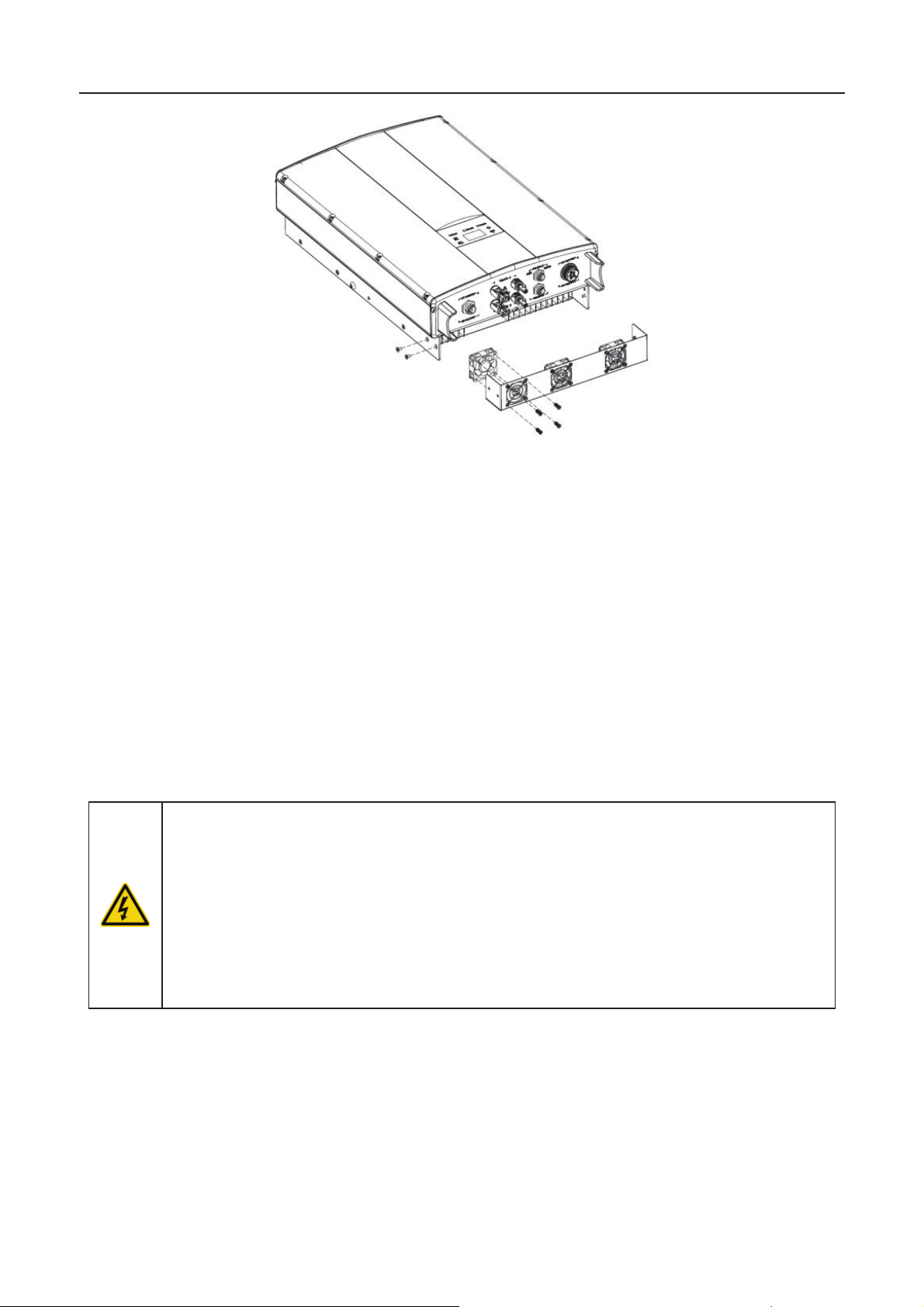
(3) Disassemble the inverter in the reverse of the installation procedure in section 4.
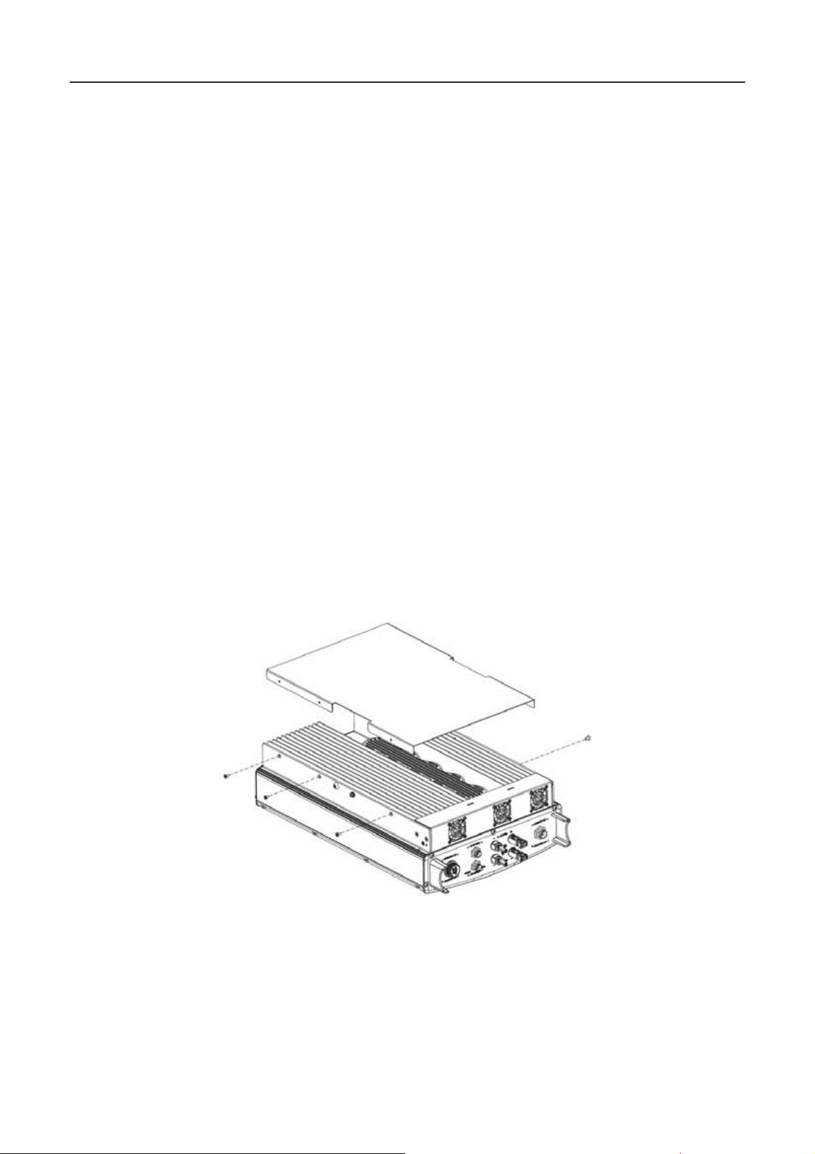
(4) Remo ve th e sc rews an d c over of the h eat si n k or fan case. As sh own in Fi gure 5. 1 and
Figure 5.2.
Figure 5.1 Disassembly of the heat sink
33
Page 36
iMars grid-tied solar inverters Operation
the inverter must be
he maint enanc e work can on ly be carr ied out aft er
Only pr of essi onal electr ic ians c an perf orm f an mai nt enanc e an d r eplac emen t
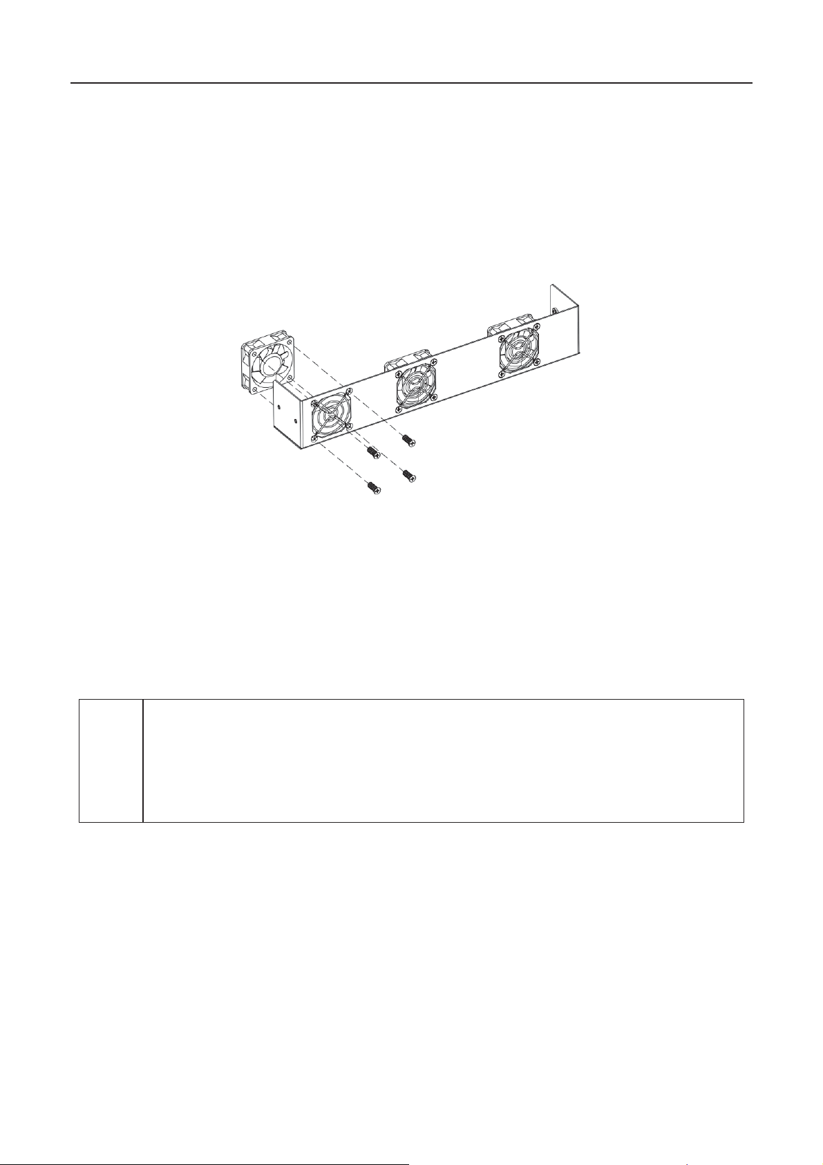
Figure 5.2 Disassembly of fan box
(5) C l ean t h e in verter h eat s in k and fan wit h a s oft brus h or vacuum cl eaner.
(6) Install the screws and cover of the heat sink or fan case to their original positions.
(7) Reinstall the invert er to its or ig in al positi on in accord ance wit h sectio n 4 .
(8) Repeat th e op er at i on c ontents of secti on 5.1.
(9) Rest art the in verter.
Replace the fan
If the inverte r has high temperatures or the fan is running abnorm ally, replace the fan. This
oper ati on must be p erform ed b y pr of ess i on als.
z The inverter must be shut down and all power inputs of
disc onnected befor e mai nt en ance wor k b egi ns .
z W ait at least 10 min utes , t
the capacitor inside the inverter has been discharged .
z
work.
The fan replacement steps are as follows:
(1) D is c onn ec t AC circu it breaker.
(2) Turn the DC switch to the "OFF" position.
(3) Wait at least 10 minutes.
(4) D is c onn ec t all el ectric al con n ections from the bottom of th e in verter.
34
Page 37
iMars grid-tied solar inverters Operation
Note
Once the inverter stops due to an alarm, it is forbidden to start the machine
immediately. The cause should be identified and all faults must be eliminated
before starting up. Inspections should be carried out in strict accordance with the
(5) Lift the inverter with the help of others and remov e the inverter from th e wall.
(6) P l ac e th e in verter on th e o p er ati ng plat f or m.
(7) Disassemble the fan case as shown in Figure 5.2.
(8) As shown in Figure 5.3, remove the damaged inverter fan, install the good fan to the
original position, and connect the fan power supply and control cable.
Figure 5.3 Replace the Fan
(9) I ns t all the screws and cover of the h eat si n k or f an b ox t o th eir origin al positi ons.
(10) Reins t all t h e in verter to its orig inal pos ition in accord ance with secti o n 4.
(11) Repeat the operation in section 5.1.
(12) Restart the inverter.
z
procedures in section 5.1.
35
Page 38

iMars grid-tied solar inverters Display panel
6 Display panel
This ch apt er desc ribes th e p an el dis playi ng an d h ow to operat e on th e pan el, whic h in volves th e
LCD display, LED indicators and operatio n panel.
36
Page 39
iMars grid-tied solar inverters Display panel
Inverter state
indicators
No power on. All indicators off
Self-inspection
Green indicator blinks in every 0.
Power on
generation
Gr een ind icator k eeps on , oth er s off
Grid
(1)
, but clock fault (A007);
(2)
(A001 or E001);
(3)
but fan fault(E006 or
E012);
Green
ecoverable
Inverter stand
he public grid fault(A001, A003,
A004, A005or A006);
Y
6.1 LED in di c at or s
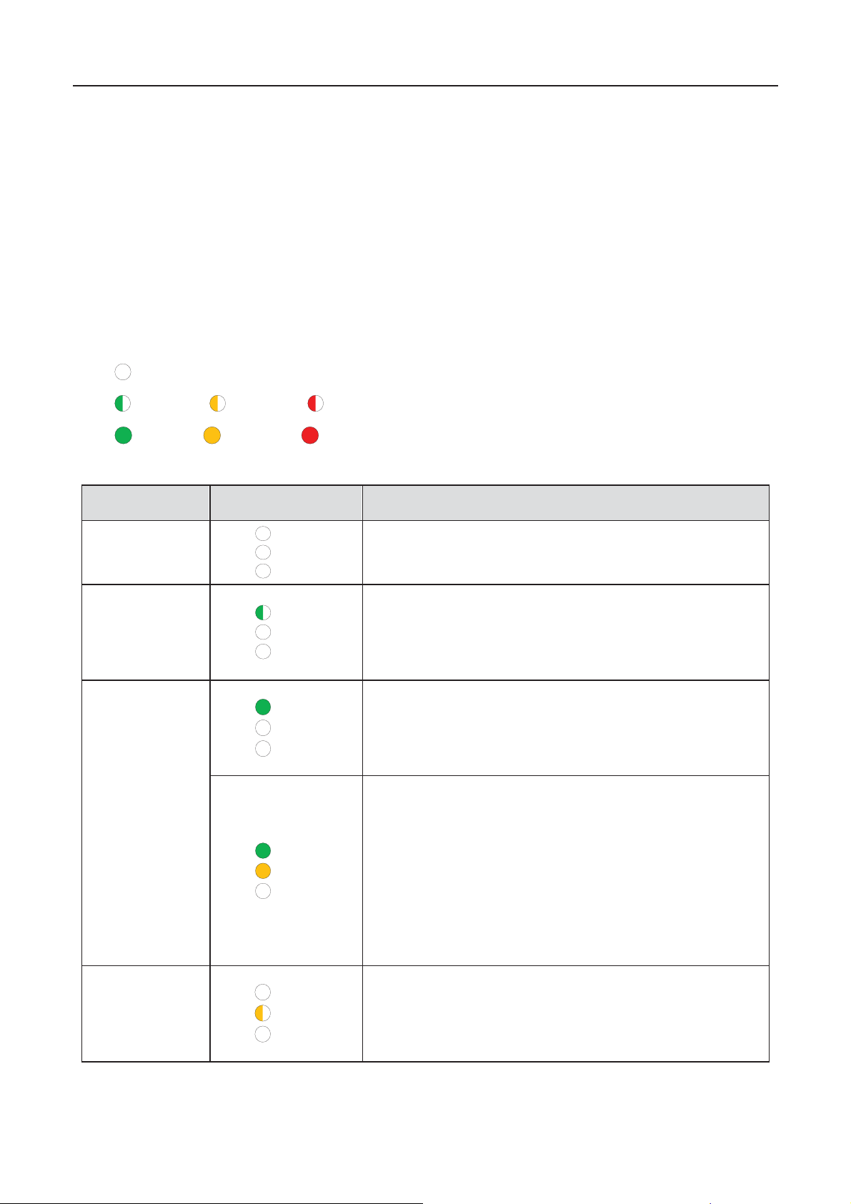
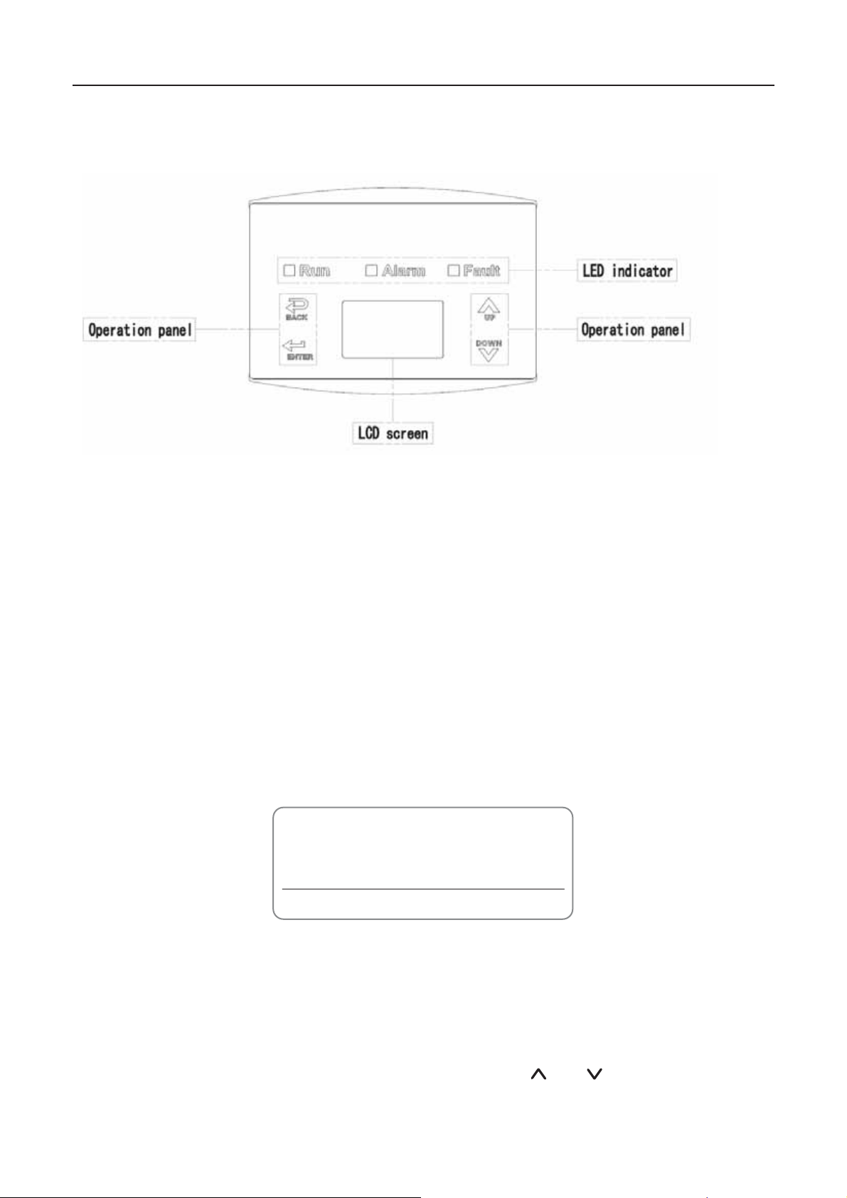
Ther e ar e three LED in dicators on t h e pan el :
(1) “Run”, operation indicator, green;
(2) “Warn” recoverable fault indicator, yellow;
(3) “Fault”, unrecoverable fault indicator, red.
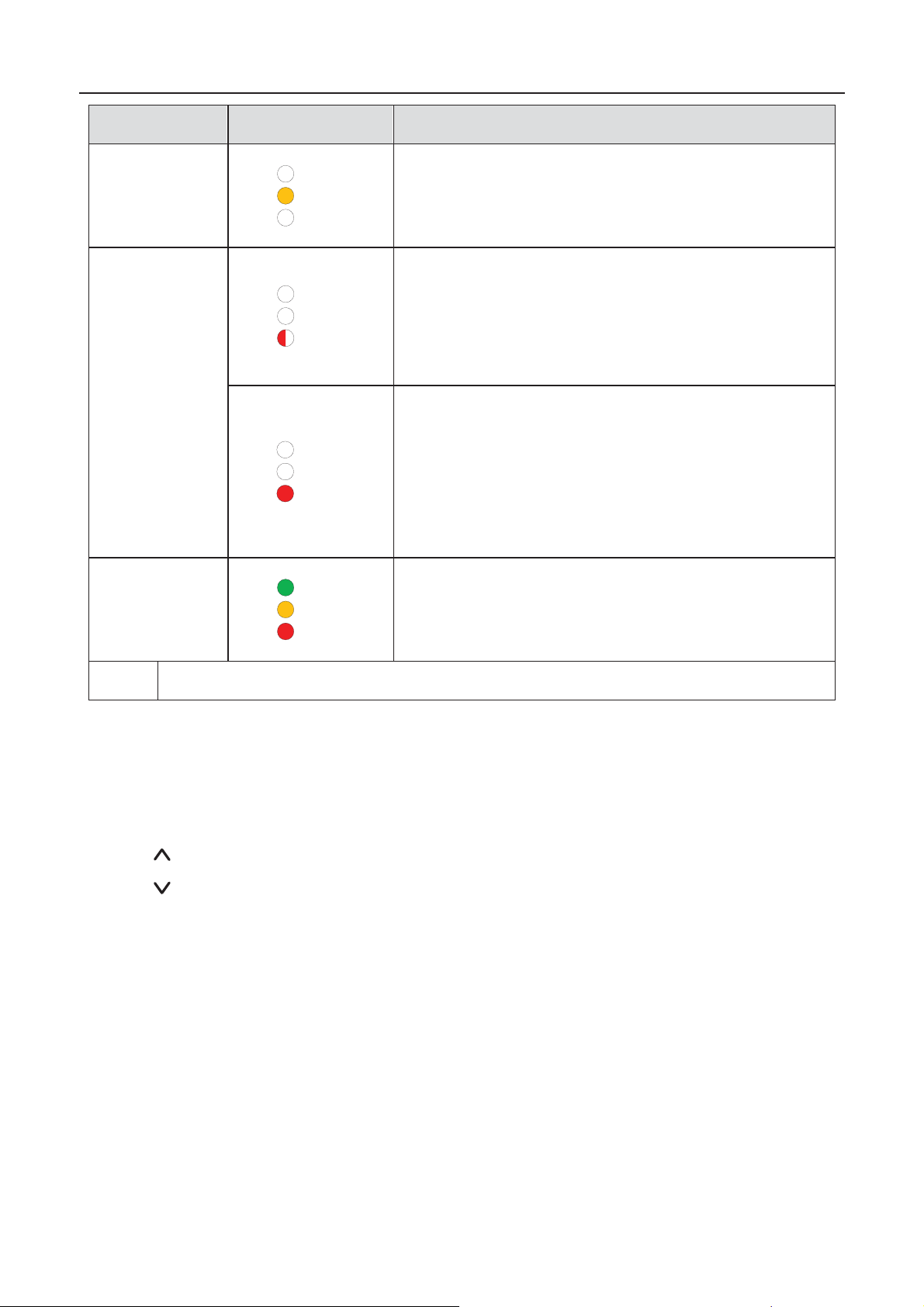
The inverter state includes 6 states of stand-by, self-inspection, power generation, recoverable
fault an d unrecoverable faul t; LED in dicat ors are on, off and bli nk ing. Please refer to tab l e 6-1 for
detailed state of inverter and LED indicators state.
“
”: LED i ndicator i s off;
“
” (green), “ ” (yellow), “ ” (r ed): LED indic ato r is bl in king at every 0. 25S or 0.5 S ;
(Green), “ ” (yellow), “ ” (red): LED indicator is on.
“
Table 6-1 Inverter state and LED indicators
Stand-by
Power
LED
Run
Warn
Fault
Run
Warn
Fault
Run
Warn
Fault
Run
Warn
Fault
Description
.
25 s, oth ers of f.
Grid-tied power generation
Gri d-tied p ow er generation , but DC in put fault
Grid-tied power generationˈ
and ready for self-inspection
.
-tied power generation.
R
fault
Run
Warn
Fault
and yel l ow ind icator k eeps on, others off.
-by. T
ell ow indicat or blin ks in ev ery 0.5s , others off
37
Page 40
iMars grid-tied solar inverters Display panel
Inverter state
indicators
(1)
emper ature abnormal(E006) ;
(2)
Y
Unrecoverable
fault
H
E003, E004, E005, E008,
E009, E011, E0 13 or E0 15
couple the inverter
from the system before maintenance .
R
C
power energy of
the inverter (E007, E010, E014, E017, E018 or E020).
D
maintenance.
R
Artificial
turned off
S
All
indicators are on.
Note
P
lease refer to chapter 6 and 8 for detailed fault information and troubleshooting.
LED
Run
Warn
Fault
Run
Warn
Fault
Run
Warn
Fault
Inverter stand-by. T
Inverter stand-by. DC input fault (E001);
ell ow indicat or keep s on, ot h ers off
ardware or software fault (
ed indicator bli nks in ev ery 0.5s, oth ers off
urrent-leakage or unqualified output
e-couple the inverter from the system before
ed indicator keep s on, others off
Description
). De-
Run
Warn
Fault
6.2 Oper ati o n pa nel
Ther e ar e 4 butt ons on t h e p an el:
(1) “ESC”, exit and return ;
(2) “
(3) “
(4) “ENT”, enter.
”, back to the front page and data increasing;
”ˈto the next page and data decreasing;
top after the communication or panel command.
38
Page 41
iMars grid-tied solar inverters Display panel
6.3 LCD screen
Figure
6.1 Operation panel
All information is displayed on the LCD screen. The background illumination of LCD screen will go
out to save power if there is not button operation in 15 seconds. But it can be activated by pressing
any but t on. Press “ENT” t o ent er int o the main int er fac e if the bac k ground illumi nation is on. A l l
parameters can be viewed and set on the interface.
Ther e ar e m ain int er face and menu int er f ac es on t h e LCD s c reen, of whic h t h e m ain int erfac e is
the def ault one after p ower on, w hi l e th e men u int erfaces are used to watc h an d s et par am eters or
other manual operation, suc h as viewing the monitoring parameters, history rec ord, system
information, statistics and fault information and setting the displayed language, time,
commu nicati on address , p assword and factor y def aul t s .
Text Parameter
Display Area
Fault CodeStatus Area
Figure 6.2 Main interface
The main interface of the LCD screen is shown as the figure above:
(1) The curve displays the power changing at the current day;
(2) The w or ds on the scr een dis play the curr ent key parameter s of the inver t er. Thr ee li n es of
words are displayed at a time, but if the inverter is in operation or stand-by state, the words
are rolling forward at every 3s. And the user can press “
information freely;
” or “ ” to look up th e
39
Page 42
iMars grid-tied solar inverters Display panel
(3) 5 states of the inverter are displayed on the screen;
(4) If the inverter is in fault or warning state, up to 8 corresponding fault codes can be
displaying on the screen.
6.4 Functi on s op er at io n
Most of the parameters can be viewed and set through the LCD screen and operation panel.
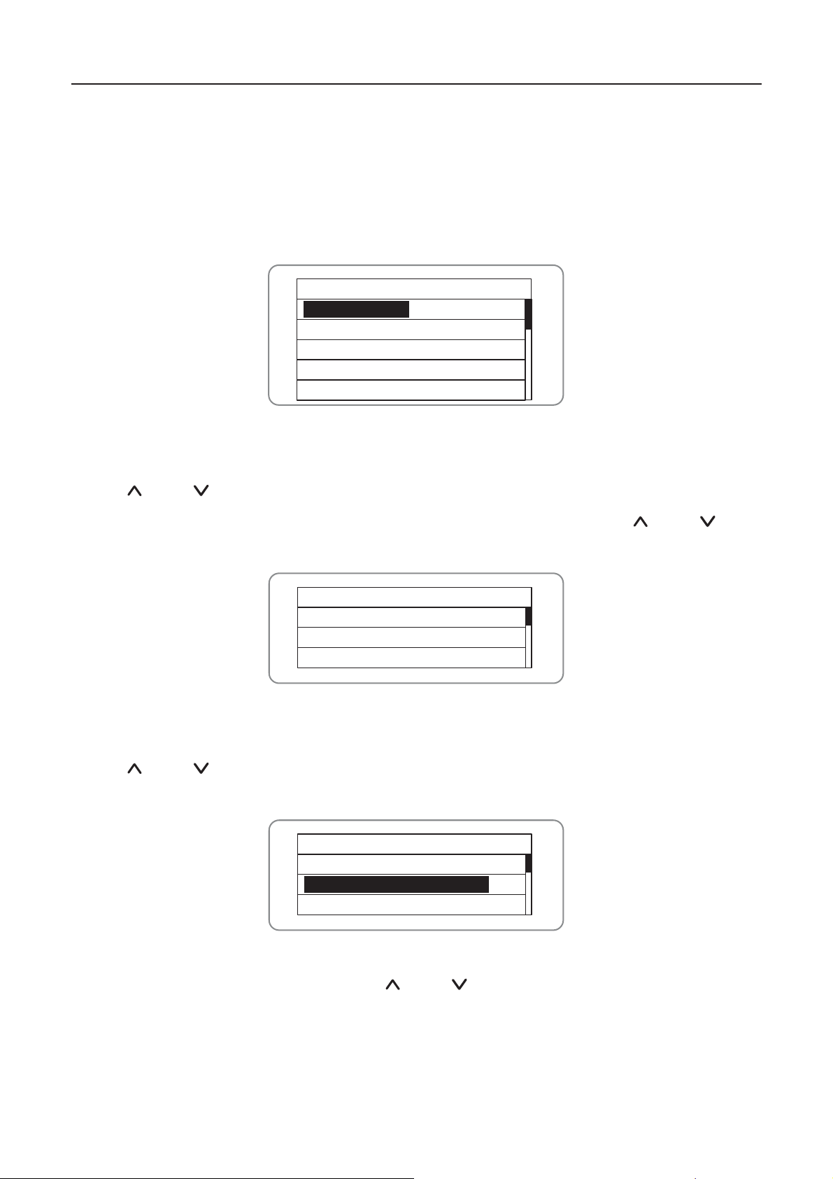
Main Menu
Monit Param
Statistics
Setup
System Info
Fault Info
Figure 6.3 Main interface
6.4.1 Monitoring parameters
Press “ ” and “ ” in the main interface to select “MonitParam”, and then press “ENT” to view
the parameters which is shown in figure 6.4. Go the front or next page through “
return through “ESC”.
Current State
E-tod: 0Wh
$-tod: 噉0.00
P-in : 0.00kW
” and “ ” and
Figure 6.4 Moni toring parameters
6.4.2 History
Press “ ” and “ ” in the main interface to select “History”, and then press “ENT” to view the
param et er s whic h is sh ow n in fi gure 6.5 .
History 0
2012/01/05 11:32:16
A005: Grid under freq
Figure 6.5 History parameters
There are 32 history records in total. Press “
“ESC” to exit. The numbers on the top right is the serial No. of the record and the numbers in the
second line display date when faults occur and settled. If the color of the third line illuminates, the
fault occurs, if not, the fault is solved.
” and “ ” to revi ew th e history rec ord and pr ess
40
Page 43
iMars grid-tied solar inverters Display panel
Content
Detailed
T
CO2
reduction
T
reduction
6.4.3 Statistics
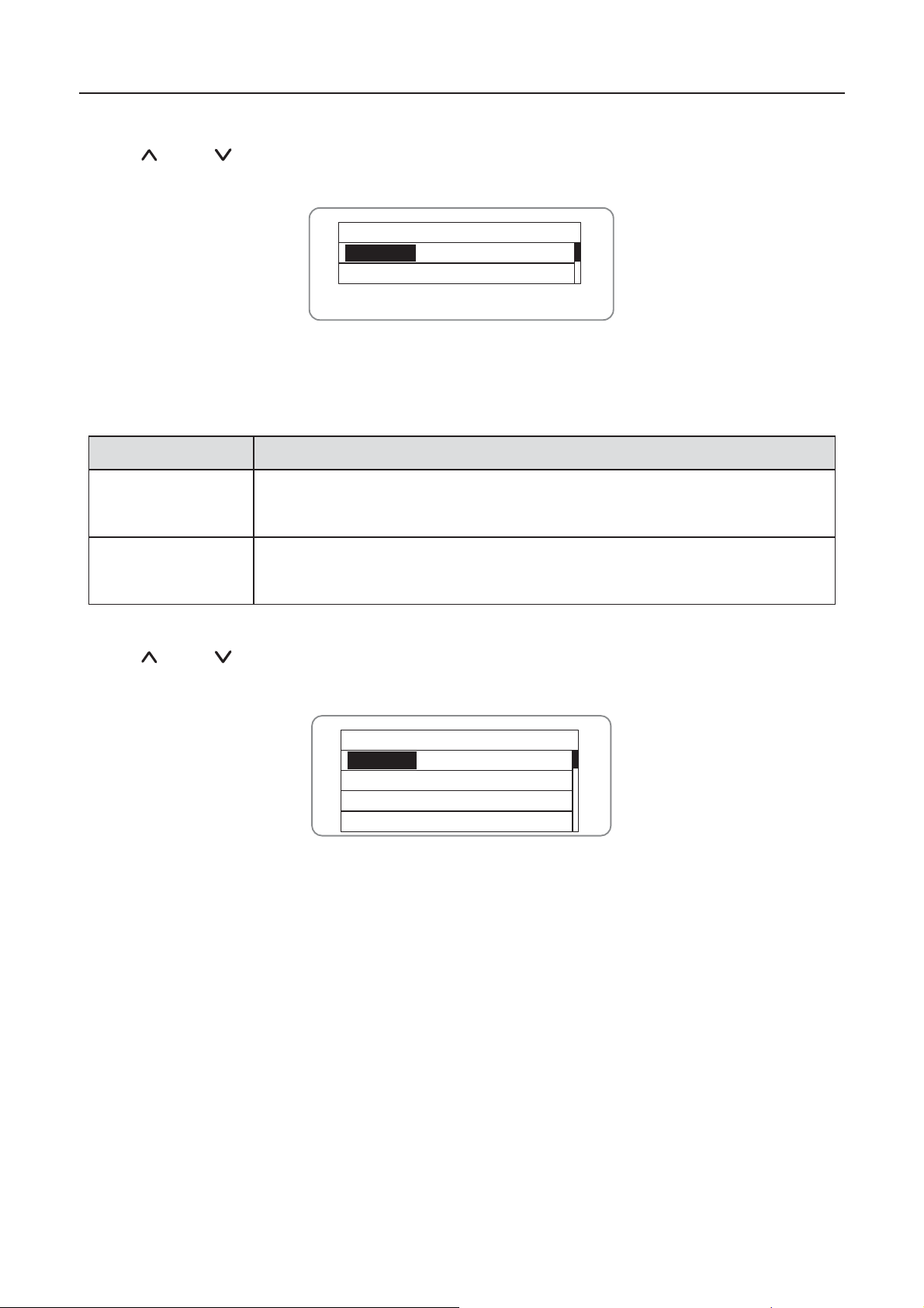
Press “ ” and “ ” in the main interface to select “Statistics”, and then press “ENT” to view the
param et er s whic h is sh ow n in fi gure 6.6 .
Statistical Menu
Lifetime
Today
Figure 6.6 Statistic information
The information in table 6-2 can be v iewed in the statistical menu.
Table 6-2 Statistic information
Lifetime
otal operation time, total power produced, total power saved, total
in lif eti m e
otal power produced, total power saved, peak power and total CO2
Daystatistics
in current day
6.4.4 Parameter settings
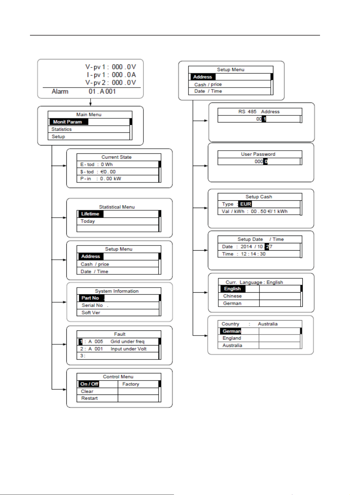
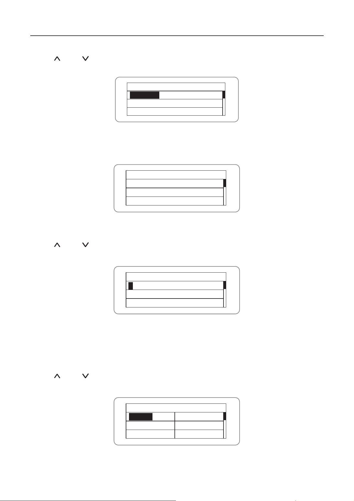
Press “ ” and “ ” in the main interface to select “S etup Men u ”, and then press “ENT” to view
the parameters which is shown in figure 6.7.
Setup Menu
Address
Cash/price
Date/Time
Language
Figur e 6. 7 S ett i ng inform at i on
Parameters can be set in this i nterface.
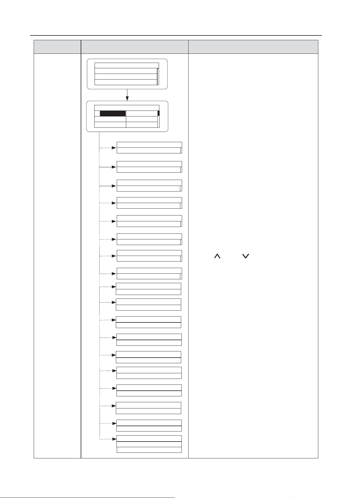
41
Page 44
iMars grid-tied solar inverters Display panel
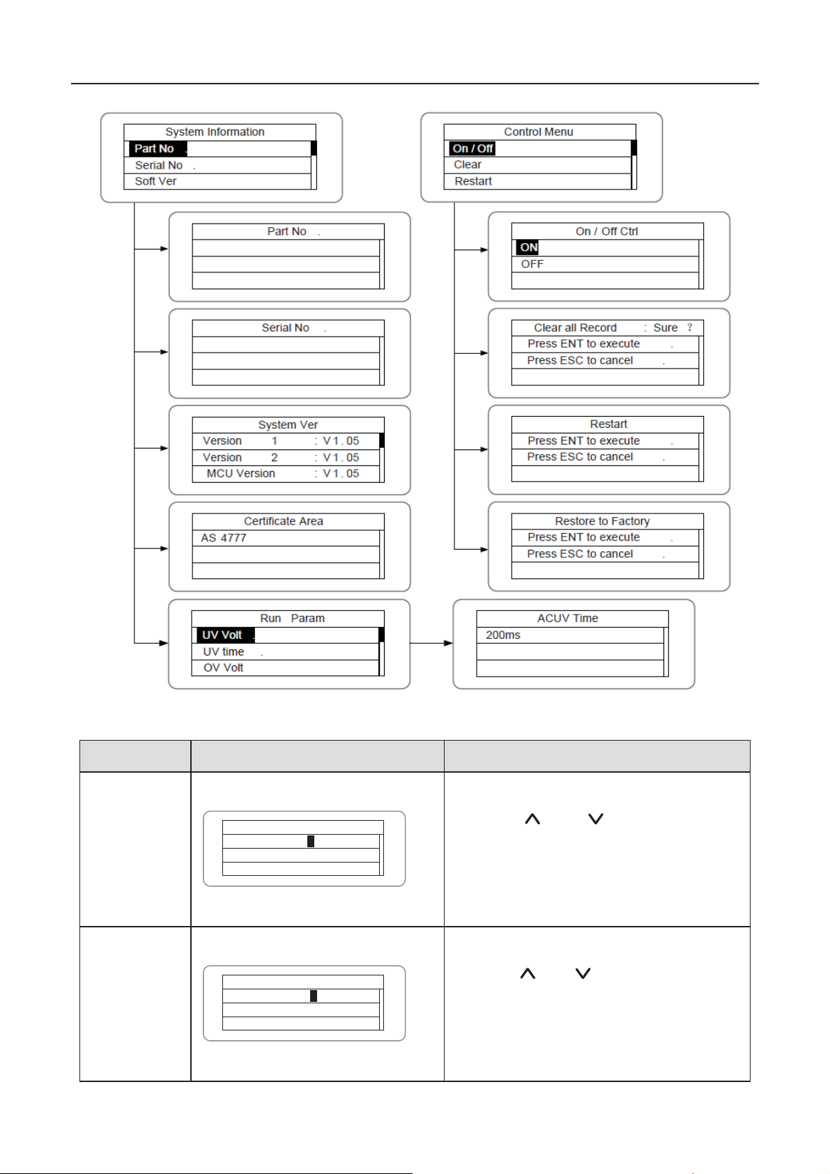
LCD menus:
42
Page 45
iMars grid-tied solar inverters Display panel
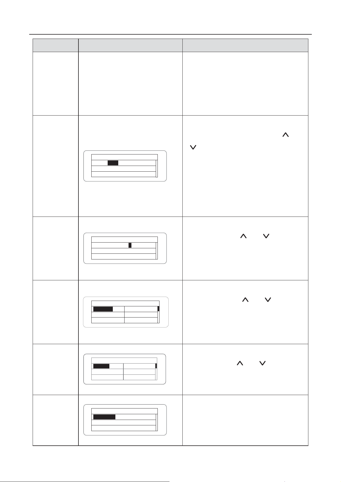
Setting item
RS485
ddress
Enter int o th e int erf ace and edit t he d ata
through
nd then press
“ENT
editing
the three bits, press
to save the
editi on an d p
password
Enter into th e int erface and ed it th e d at a
through
nd then press
“ENT
editing
the four bits, press
editi on an d press
Table 6-3 Parameters setting
LCD display Instruction
RS485 Address
A
User
User Password
001
0000
“ ” or “ ”. A
1
0
43
” again to the next bit. After
“ENT”
ress “ESC” to exit.
“ ” or “ ”. A
” again to the nex t b it. After
“ENT” to sav e the
“ESC” to exit.
Page 46
iMars grid-tied solar inverters Display panel
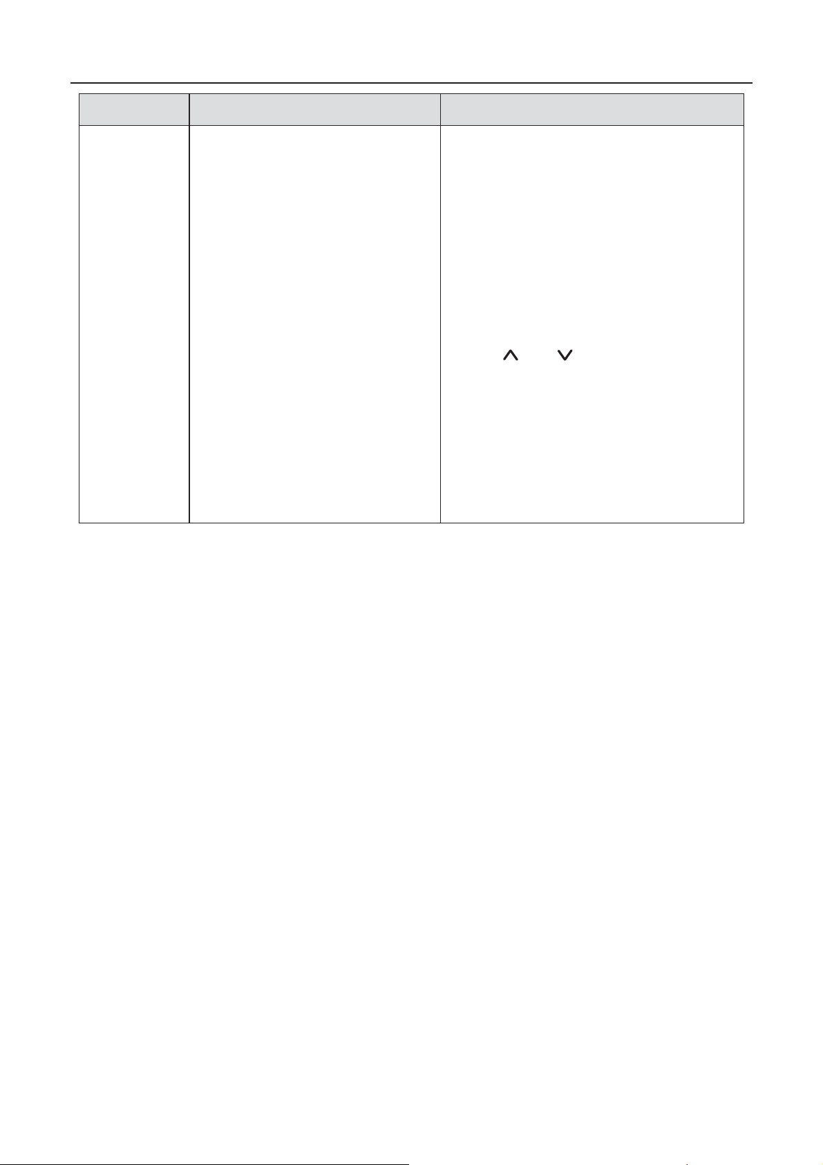
Setting item
LCD display
Instruction
T
t he u ser
can ent er int o t h e s etting inter fac e
without password.
f the password is not
“0000
setting interface with password.
Setup Cash
E
currency type and cash through
or
“
again to the
next line.
th e four bit s , press
“ENT
“ESC
The currency ty pes include EUR, POD,
CN Y and USD.
etup
Date/Time
Enter into th e int erface and ed it th e d at e
and time through
nd then
press
fter
editing
to save
the edit i on an d p r ess
anguage
E
language through
nd then
press
again to save the edition
and press
T
Select
Country
E
country through
nd then
press
again to save the edition
and press
Setup m od e
T
“independent”
“independent
independent
MPPT of Track A and Track B;
parallel
he default password is“0000”;
I
”, the user can enter into the
nter into the interface and edit the
“ ”
”. And then press “ENT”
Setup Cash
EUR
Type: EUR
Val/kWh: 00.50噉/1kWh
Aft er edit in g
” to save the edition and press
” to exit.
S
Setup Date/Time
Date: 2012/01/15
Time: 12:14:30
1
“ENT” again to the next l ine. A
“ ” or “ ”. A
the four bits, press “ENT”
“ESC” to exit.ˈ
nter into the interface and edit the
Curr. Language : English
L
English
Chinese
German
Dutch
“ENT”
“ESC” to exit.
“ ” or “ ”. A
he default language is En glish.
nter into the interface and select
Country : Australia
Germany
England
Australia
Greece
Denmark
Holland
“ENT”
“ ” or “ ”. A
“ESC” to exit.
Independ
Parallel
Setup Model: Independ
he DC input mode includes
and “parallel”:
mode” is the
“
44
Page 47
iMars grid-tied solar inverters Display panel
Setting item
LCD display
Instruction
mode” is the parallel MPPT of Track A
and Track B.
T
The input mode setting is invisible if the
inv erter is in power generation.
t is only
available during DC p ow er on an d AC
power off.
P
tting
mode and press
setti ng or
If the situat ion of section 6.4.8 occurs, it
is necessary to switch the DC input to
“parallel
he default mode is “independent”.
I
ress “ ” or “ ” to select the se
“ENT” to save the
“ESC” to return.
” mode.
45
Page 48
iMars grid-tied solar inverters Display panel
Setting item
LCD display
Instruction
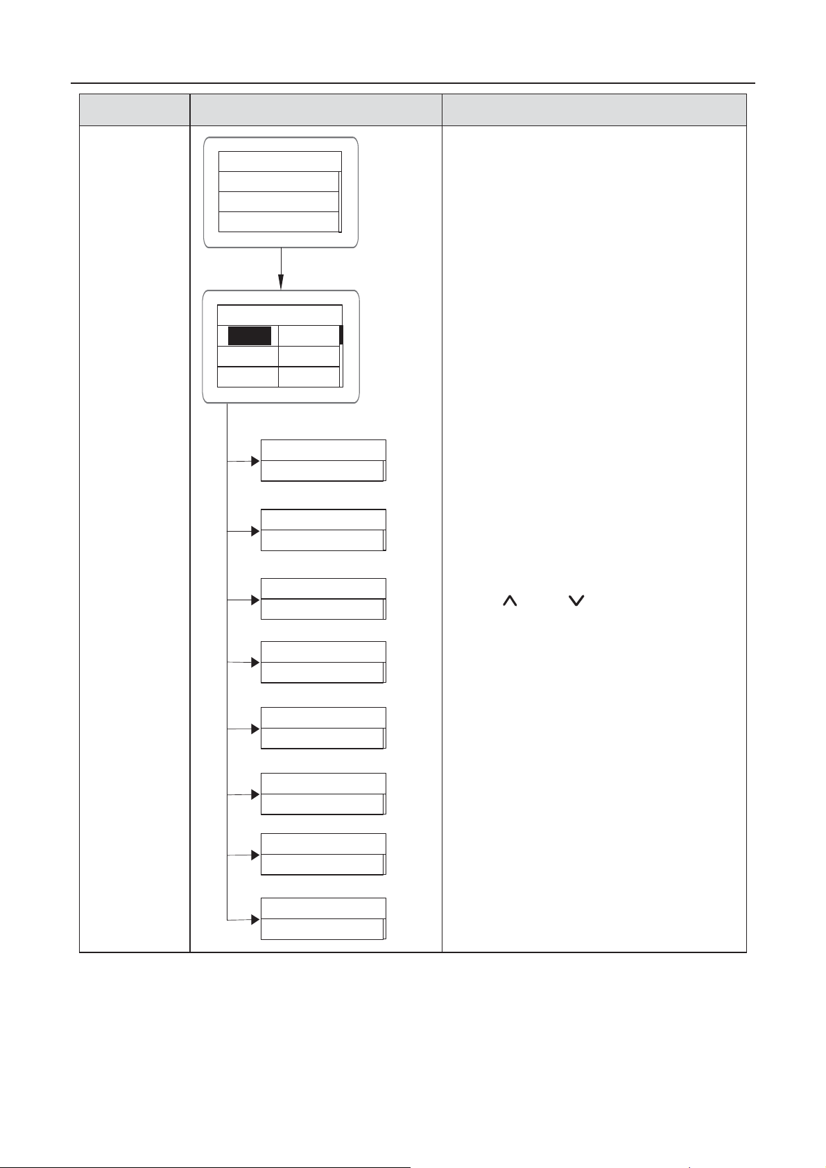
Run Par am
Passw or d is required wh en ent er int o the
interface of “Run Param”. Get the
password
from the supplier if necessary.
Set ACUV Volt, ACUV time and others
under the related submenus, and then
press “
finally press “ENT” to confirm.
Input password
0000
Run Param
UV Volt
UV time
OV Volt
OV time
UF Freq
UF time
ACUV Volt(phase volt)
184V
0.20s
263V
0.20s
47.6Hz
0.20s
51.4Hz
0.20s
ACUV Time
ACOV Volt(phase volt)
ACOV Time
ACUF Freqency
ACUF Time
ACOF Freqency
ACOF Time
” and “ ” to modify, and
46
Page 49
iMars grid-tied solar inverters Display panel
Setting item
LCD display
Instruction
Run Par am
There are 2 protections under
G83/G59(UK) and PEA(Th ailand)
stan d ards , and th er e is on l y on e
protection under other grid tied standard.
Set ACUV Volt,
ACUV time and others
under the related submenus, and then
press “
finally press “ENT” to confirm.
Generally, it is only nec essar y t o s et
ACUV and ACUF value for ACU V and
ACUF protection. And it is necessary to
set ACOF1 and ACOF2 together for
ACOF protection.
Input Password
0000
Run Param
UV volt 1
UV time 1
OV volt 1
OV time 1
UF Freq 1
UF time 1
ACUV Volt(phase volt)
115V
00.04s
309V
00.02s
47.99Hz
·
00.12s
50.50hz
00.12s
196V
0.19s
252V
ACUV Time
ACOV Volt(phase volt)
ACOV Time
ACUF Frequency
ACUF Time
ACOF Frequency
ACOF Time
ACUV Volt(phase volt)
ACUV Time
ACOV Volt(phase volt)
” and “ ” to modify, and
01.90s
49.49Hz
ACUF Frequency
595s
ACOF Frequency
50.2Hz
115s
060s
OFF
ON
ACOV Time
ACUF Time
ACOF Time
Run Restart Time
Island protect:on
47
Page 50
iMars grid-tied solar inverters Display panel
6.4.5 System Information
Press “ ” and “ ” in the main interface to select “S ys tem Inform ation”, and then press “ENT” to
view the parameters which is shown in Figure 6.8.
System Information
Part No .
Serial No .
Soft Ver
Figure 6.8 System information
The system in formation include “prod uc t m od el”, “serial No.”, “software version” and “certificate
version”.
System Ver
Version1 : V1.05
Version2 : V1.05
MCU Version : V1.05
Figure 6.9 System version
6.4.6 Faults
Press “ ” and “ ” in the main interface to review the fault history, and then press “ENT” to view
the sub-menu which is shown in figure 6.10.
Fault
1: A005 Grid under freq
1
2: A001 Input under Volt
3:
Figure 6.10 Fault information
There are 8 pieces of fault information in the record which is shown in figure 6.10; otherwise it will
display “No Fault!” Refer to sec ti on 6.4.2 for more d etai led infor m ati on.
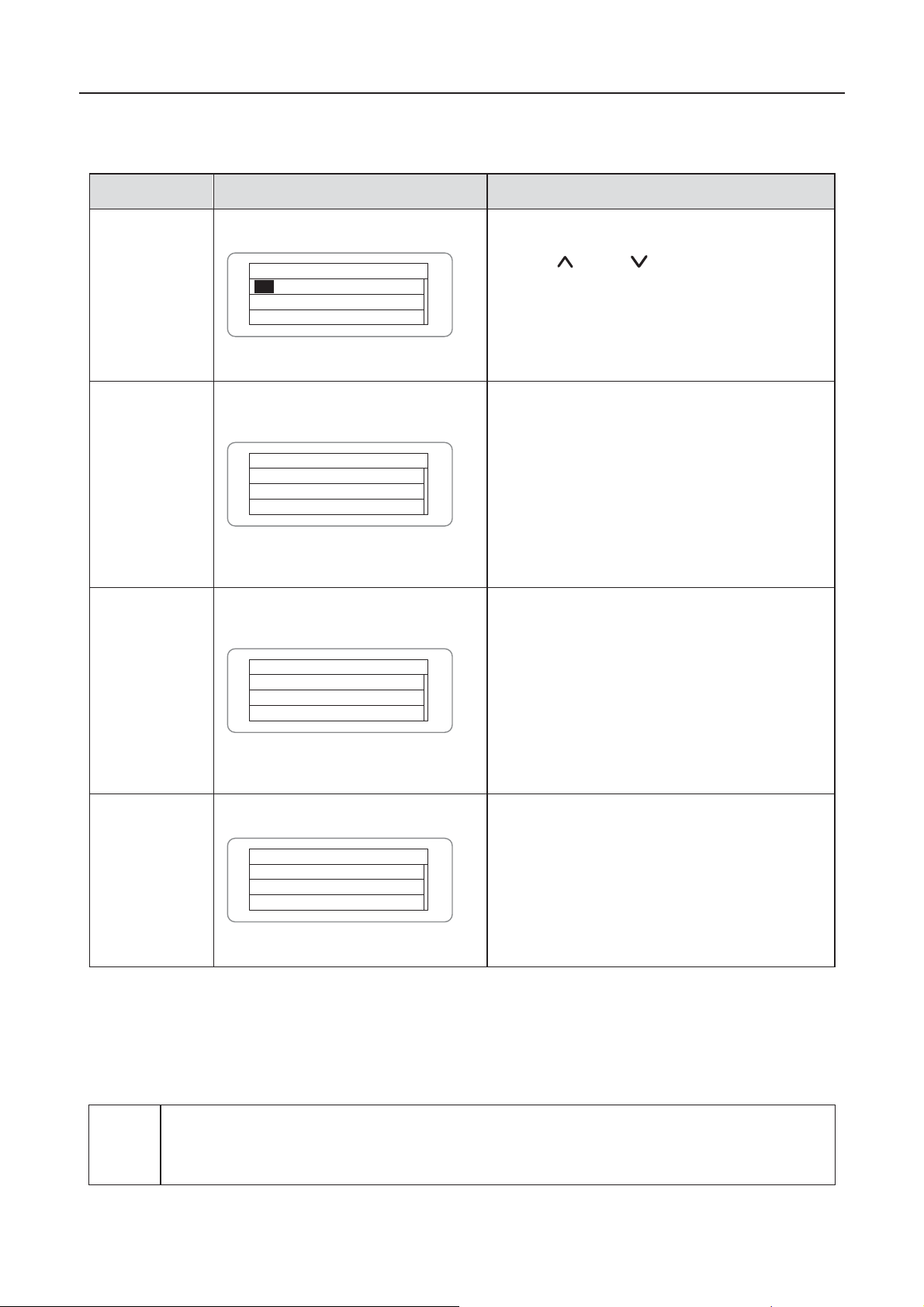
6.4.7 Inverter control
Press “ ” and “ ” in the cont r ol in terf ac e, and then press “ENT” to view the s ub-men u wh ic h is
shown in figure 6.1 1.
Control Menu
On/Off
Clear
Restart
Factory
Figure 6.11 Control inte rfa ce
48
Page 51
iMars grid-tied solar inverters Display panel
Control item
n/Off
control
C
through the panel.
P
interface to select the operation. Press
“ENT
to ensu r e th e op er at i on an d press
“ESC
estart
Restart the inverter through the panel.
And save the all settings and operation
record.
P
to ensur e rest arting and th e
invert er will b egin t o self
inspect or press
“ESC
Record clear
P
to ens ur e cl ear all records or
press
“R
is to clear all setting
parameters through the panel,
to
the factory setting and save all history
operation records.
estore to
“R
is to clear all setting
param et er s and his tory op eration r ecords
through the panel,
to the factory
setting.
to ens ur e cl ear or
press
Note
Only wh ere ther e is more than 10 0V DC vol tag e input , LCD disp lay w orkin g, and
modify the inverter DC input mode via the LCD
scr een an d k eyp ad.
Refer to the table below for detailed information.
Table 6-4 Inverter control
LCD display Instruction
ontrol the “On/Off”
R
O
ON
On/Off Ctrl
OFF
Restart
Press ENT to execute.
Press ESC to cancel.
Clear all Record: Sure˛
Press ENT to execute.
Press ESC to cancel.
ress “ ” and “ ” in the control
”
” to return.
ress “ENT ”
-
” to return.
ress “ENT”
“ESC” to return.
ecord clear”
restore
estore to factory”
R
Restore to Factory
Press ENT to execute.
Press ESC to cancel.
factory
Press “ENT”
“ESC” to return .
6.4.8 Mode settings
The default mode of series grid-tied solar inverter is “independent”. But if the current of solar
modules are joined into the inverter as figure 6.12 shows, it is necessary to switch the mode into
“parallel”.
z
AC switch off, can query and
49
restore
Page 52
iMars grid-tied solar inverters Display panel
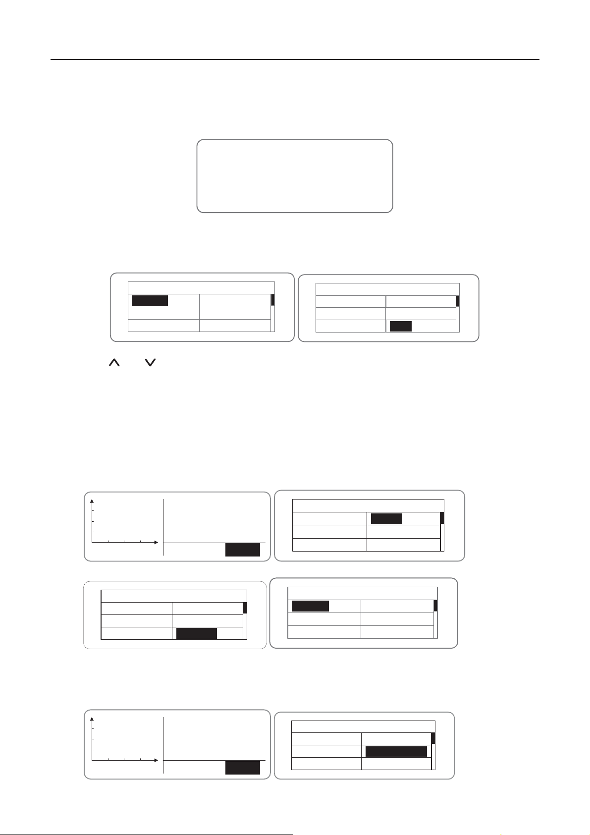
6.5 Grid certification choice
Power on the inverter by DC input for the first time or after Restore factory settings, it will appear
on the LCD sc r een prompt s as f oll ows :
SOLAR INVERTER
InitialingĂĂWaiting
>>>>>>>
Waiting a few seconds later, in the LCD screen will appear a list of countries as follows, requiring
the user to choose what country of use. As shown below:
Country: Unset
Germany
UK
Australia
Greece
Denmark
Holland
Country: Unset
Greece
Denmark
Holland
China
Thailand
Other
Press the “
” or“ ” button to navigate the country , press the ENT button to complete the
setting.
After determine the location, please follow the user manual required with the proper use of
inverter.
The user can change the location through the following ways:
LCD Screen˖MENUėMain M enu: S etu p ėS etup Menu: CountryėCountry:
p
Alarm
V-pv1: 000.0V
I -pv1: 000.0A
V-pv2: 000.0V
h
01.A001
MENU
MENU
Monit Param
History
Statistics
Main Menu
Setup
System Info
Fault Info
Setup Menu
Address
Keypad PWD
Cash/price
Date/Time
Language
Country
Country: China
Germany
UK
Australia
Greece
Denmark
Holland
The user can query the grid certification which has been set through the following ways:
LCD Screen˖MENU→Main Menu: System Info→System Information: Cert. Area→Certificate Area
p
Alarm
V-pv1: 000.0V
I -pv1: 000.0A
V-pv2: 000.0V
h
01.A001
MENU
MENU
Main Menu
Monit Param
History
Statistics
Setup
System Info
Fault Info
50
Page 53
iMars grid-tied solar inverters Display panel
No.
Germany
System Information
Part No.
Serial No.
Soft Ver
Cert. Area
Run Param
AS4777
Certificate Area
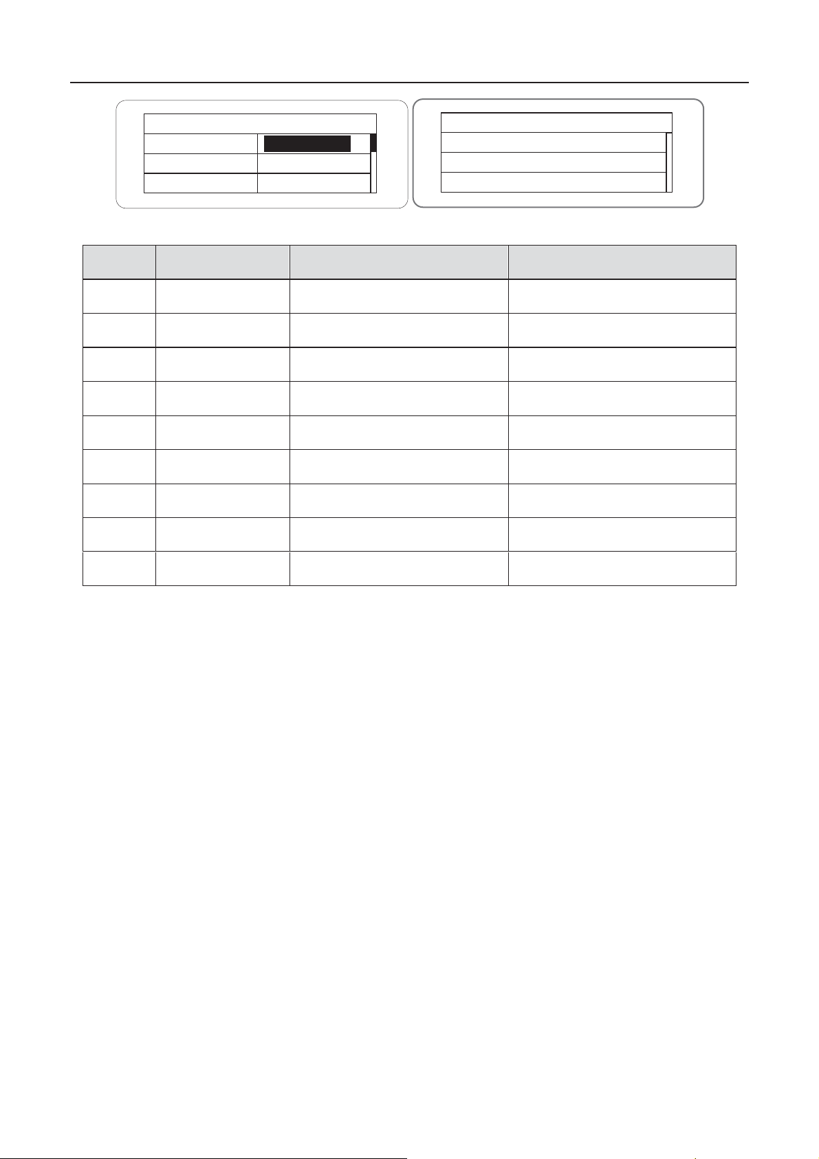
Comp arison Tabl e: Available Coun tries and th eir gri d certif icati on
Country Certification Remark
1
2
3
4
5
6
7
UK G83/G59
Australia
Greece VDE0126
Denmark
Holland C10/C11
China CQC
VDE0126& AR-N4105
AS4777
TF321
8
9
Thailand
PEA
Other VDE0126
51
Page 54
iMars grid-tied solar inverters Display panel
No.
Three-phase
voltage
Grid
frequency
VDE0126& AR-N4105
380~400V
10
11
12
13
AS4777.2&AS4777.3
415V
14
15
16
380~400V
17
18
19
380~400V
20
21
22
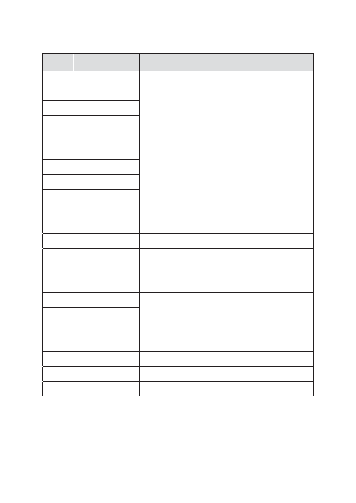
Refer ence Tabl e: Grid c ertific ation and gr id v olt age and f r equenc y of s om e c ountries
Country Certifi cation
1
2
3
4
5
6
7
8
9
Germany
France
Greece
Turkey
Romania
Slovakia
Portugal
Poland
Hungary
Switzerland
Austria
UK G83-2/G59-3 415V 50Hz
50Hz
Australia
Singapore
New Zealand
Belgium
Luxembourg
Holland
Denmark TF3.2.1
Thailand PEA 380V 50Hz
China CGC/CF001 380V 50Hz
Italy ENEL 400V 50Hz
AS/NZS3100
C10/C1 1
400~
50Hz
50Hz
50Hz
52
Page 55

iMars grid-tied solar inverters Monitoring communication
7 Monitoring c ommunication
This chapter describes the communicat ion connection of inverter and monitori ng system
(Industrial master, private computers, smart phones and so on).
53
Page 56
iMars grid-tied solar inverters Monitoring communication
7.1 Standard communication
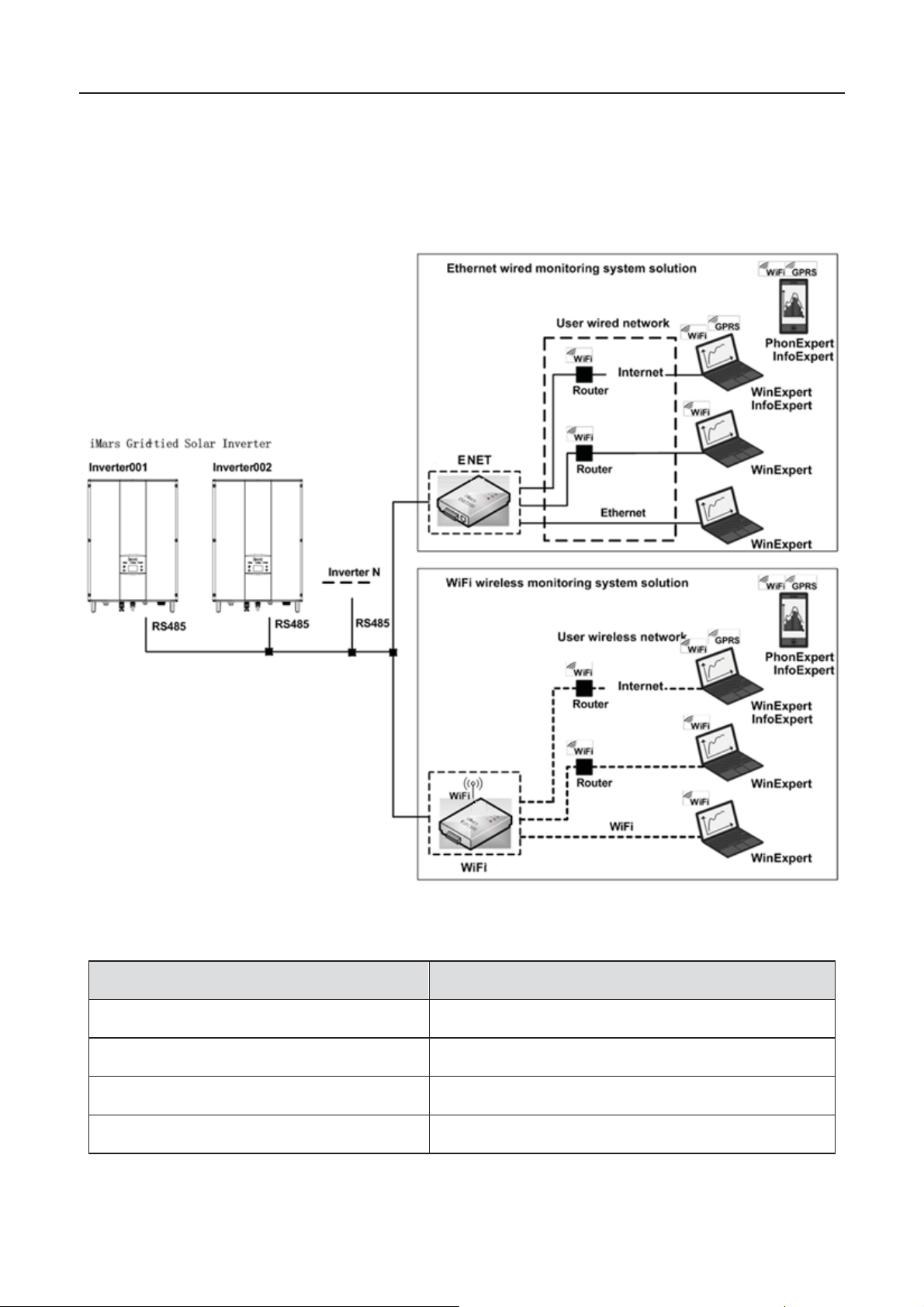
The standard communication mode of iMars grid-tied solar inverter is RS485 which includes
“RS485-M” and “RS485-S” ports. The RS485-M ports c an com muni cate w ith pr ivate c omput ers,
smart phones and so on. The system monitoring solution is shown as figure 7.1.
Figure 7.1 Monitoring system of inverter
Table 7-1 Pins on inverter instruction
Pin on inverter Definition
1 +5VDC
2 A (RS485+)
3 B (RS485-)
4 GND
54
Page 57
iMars grid-tied solar inverters Monitoring communication
9
*1'
1
23
4
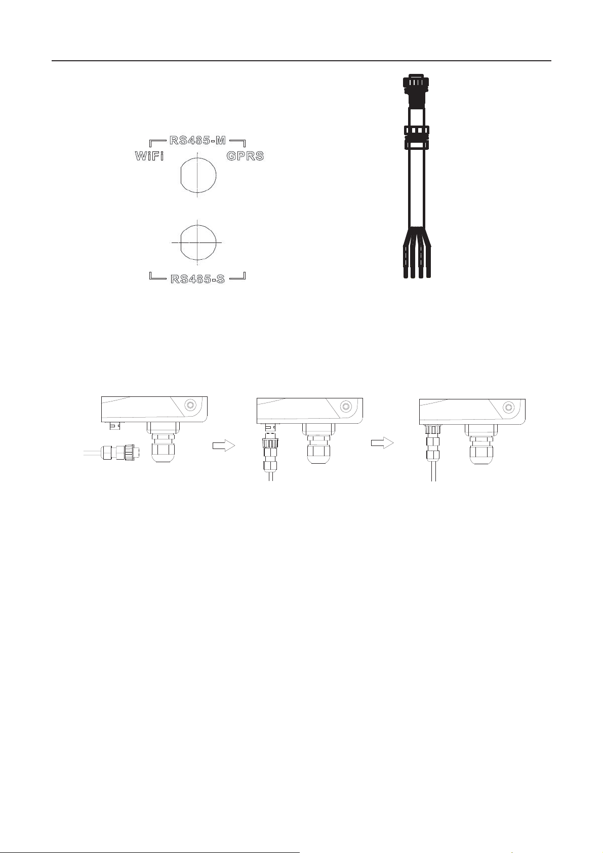
Figure 7.2 RS485 pin on inverter Figure 7.3 Communication connector
Connection steps:
(1) Weld communication cables to the RS485 terminals of the inverter as Figure 7.4 shows.
Ensure the cable corresponds to the pin as table 7-1 shows and the welding is tight
enough.
Figure 7.4 Detailed connection
(2) According to Table 7-1, connect the communication connector pinout and the user's
device, make sure the connection is correct.
(3) Please download the monitoring software “iMars WinExpert” and its operation instruction.
55
Page 58
iMars grid-tied solar inverters Monitoring communication
Optional accessories
Inverter port
Port of upper PC
GPRS converter
RS485-M
GPRS signal
ENET converter
RS485-M
Ethernet port
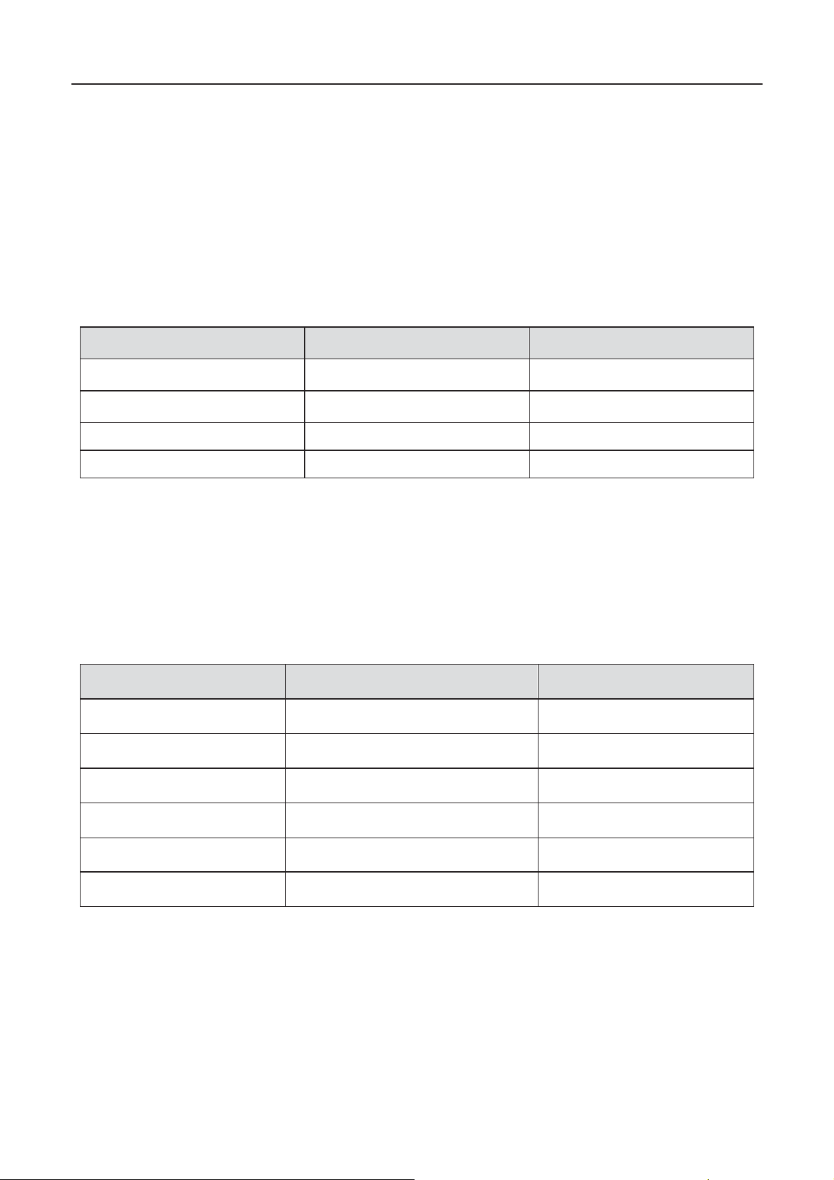
7.2 Opti on al com m u ni ca ti on
The opti on al comm un icati on m od es inc l ude E th er n et, W iFi, w hic h also need c orrespon ding
commu nicati on p ar ts and c omp onents . All oper at i on p arameters of th e in verter ar e out p ut f rom
port “RS485-M”, and then to the communication devices, finally after convertering, to the
monitoring system of upper PC as standard Ethernet, WiFi signal. See figure 7.1.
Table 7-2 Optional accessories
Ethernet converter RS485-M RJ45 plug
WiFi converter RS485-M WiFi signal
Pleas e d ow nl oad the conn ect ion instructi on, oper ati on manu al an d c om mis s i oning tools on
websit e w ww.in vt -solar.c om.
Note: the optional acce ssories a re not standard-configured.
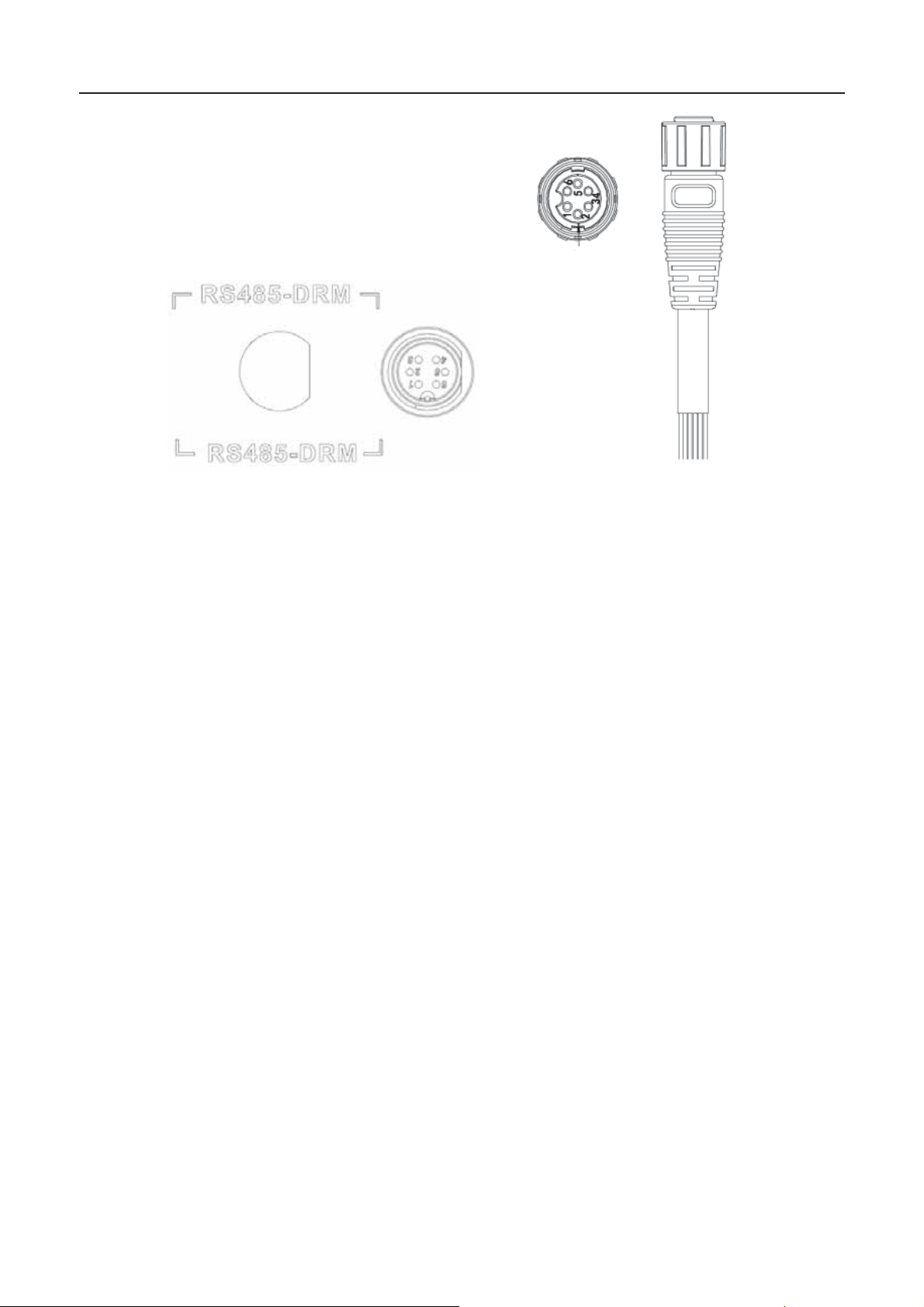
7.3 RS485-DRM ports
Table 7-3 RS485-DRM Pins on inverter instruction
Pin on inverter Colour Definition
1 Red RefGen
2 Yellow Com/DRM0
3 White DRM1/5
4 Black DRM2/6
5 Green DRM3/7
6 Blue DRM4/8
56
Page 59
iMars grid-tied solar inverters Monitoring communication
Figure 7.5 RS485-DRM pin on inverter Figure 7.6Connection cable
RS485-DRMconnection steps:
(1) Weld communication cables to the RS485-DRM terminals of t he inverter as figu re 7.6 show s;
Ensure the cable corresponds to the pin as table 7-3 shows and the welding is tight enough.
According to Table 7-3, connect the communication connector pinout and the user's device, make
sure the connection is correct.
57
Page 60

iMars grid-tied solar inverters Troubleshooting
8 Troubleshooting
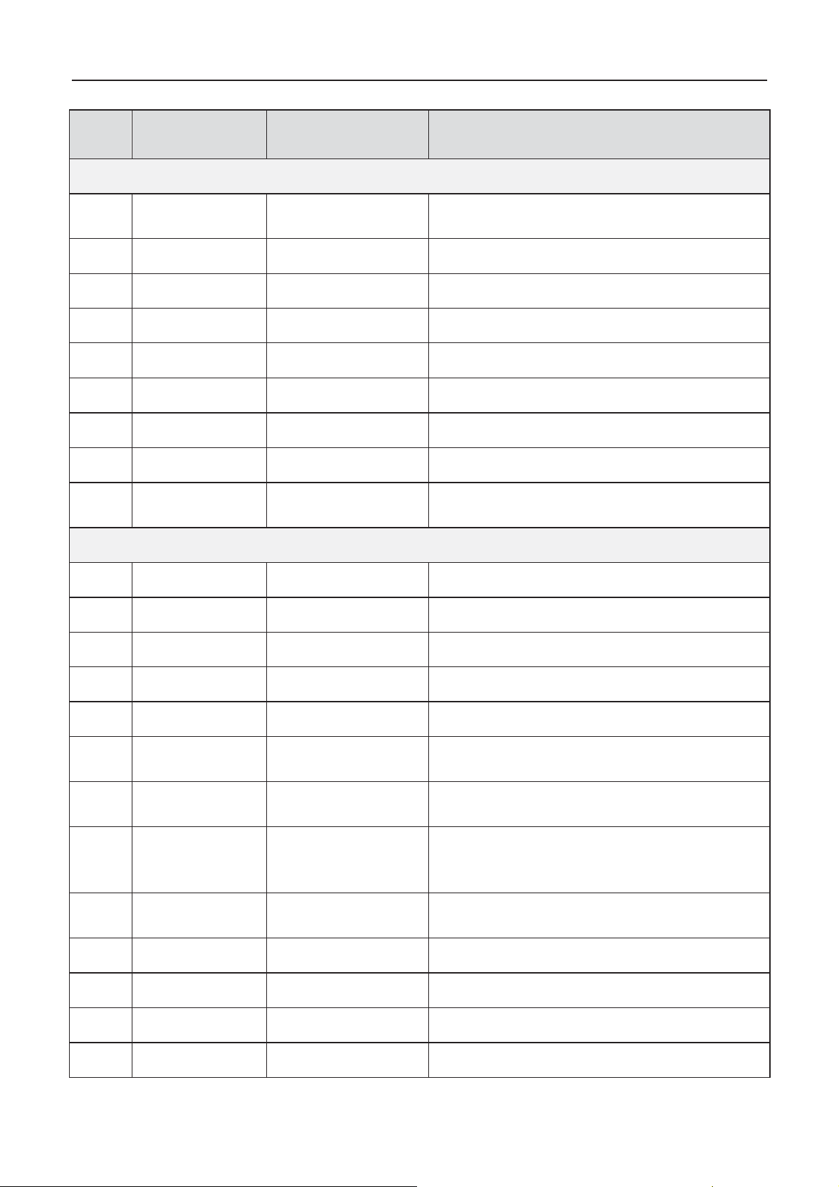
This chapter describes the fault alarm and fault code for quick troubleshooting.
58
Page 61
iMars grid-tied solar inverters Troubleshooting
Fault
code
A
A001
Input undervoltage
PV1 und er v olt age
PV2 und er v olt age
A002
Bus undervoltage
A003
AC un dervolta ge
A004
AC over v olt age
A005
AC un derfrequency
A006
AC overf requency
A007
Fail
A009
Cmd Shut
tutdown
Stop by th e oper ati on p an el or upp er PC
A011
The public grid
disconnects.
Check if inver ter AC connection is well
E
E001
Input overvoltage
E003
overvoltage
E004
Boost Fail
Voltage-boost fault
E005
AC overcurr ent
E006
vertemperature
E007
Low is olat ion
impedance
Low is olat ion impedance of th e ext ernal por t
system
E008
IGBT drive
protection
E009
Internal
communication
fault
Master-slave DSP communication di sabled
Er ror of m ast er- sla v e D SP c heck b it
E010
Fail
Huge leakage
current
Huge leakage current of the system or
inverter
E011
Relay Fault
E012
E013
E014
igh DC injection
Table 8-1 Fault code
Message
Input UV
Bus UV
Gr id UV
Grid OV
Grid UF
Grid OF
Clock
Grid Loss
Instruction Faultanalysis
DC input
Low volt ag e of th e pub lic gr i d
High vol tage of th e pu bl ic gr id
Low fr equ ency oft h e public grid
High frequency ofthe public grid
Clock al arm Wrong sett in g
Manual s
Input OV
Bus OV Bus
Grid OC
OTP O
Riso Low
IGBT drv
IntComm
ILeek
Voltage- b oos t fault of th e in verter
IGBT drive protection of the inverter
DC input overvoltage
Intern al bus v oltage
Internal AC overcurrent
Internal overtemper ature
Relay fault Internal relay fault
Fan Fail Fan fault Internal fan fault
Eeprom Memory error
Dc inject
H
Internal memory error
High DC injection during AC output
59
Page 62

iMars grid-tied solar inverters Troubleshooting
Fault
code
E015
OutputShort
O
circuit
E018
nput o verc u r rent
E019
Data consistency
fault
Inc ons is t ent gri d voltage, fr equ ency, leakage
current or AC/DC injection
E020
PowerReversed
DC power reversed
Message
Input OC
Incnst
Instruction Faultanalysis
utput short-
I
Output short-circuit
DC input overcurrent
DC power reversed
60
Page 63

iMars grid-tied solar inverters Troubleshooting
If any problem, please contact with the supplier and provide following information:
z Model of the inverter: ;
z Serial No. of the inverter: ;
z System version:üüversion 1: ;
üüversion 2: ;
üüMCU software version: ;
z Fault code: ;
z Fault description .
61
Page 64

iMarsgrid-tied solar inverters Contact us
9 Contact us
Shenzhen·China
INVT Solar Technology (Shenzhen) Co., Ltd.
Address: Room 504, No. 7 Building, Gaofa Scientific Industrial Park, Longjing, Nanshan District,
Shenzhen, China
Service hotline: +86 400 700 9997
E-mail:[email protected]
INVT group website: www.invt.com
INVT solar website ::www.invt-solar.com
62
Page 65
iMarsgrid-tied solar inverters Technical par am e ters
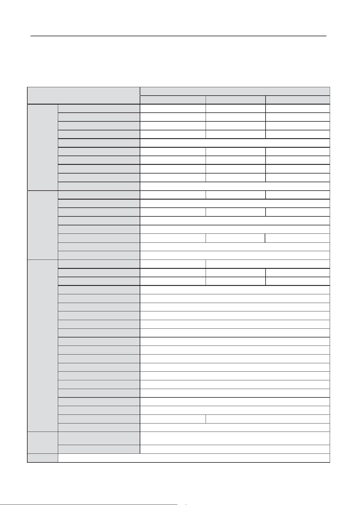
Input(DC)
Max. DC voltage (V)
Starting voltage (V)
MPPT voltage(V)
Operation voltage (V)
MPPT/strings per MPPT
Max. DC power (W)
Max. input curr ent ( A)
Isc PV
(A)
Max inverter backfeed current to the
array(A)
DC switch
Output(AC)
Max output
power
Voltage(V)/ fre quency(Hz )
Max. AC current (A)
Maximum output fault current
AC inrush current
Maximum output overcurrent
protection(A)
Power factor
Harmonic distortion
Cooling
Maximum effi ciency
European efficiency
MPPT efficiency
Protection
degree
Power consumption
Isolation mode
Protec tive class
Overvoltage category
inverter topology
Pollution degree
Operation temperature
Relati v e humidity
Max. altitude(m)
Displaying
Systerm langua ge
Communication
DC terminal
Noise dB(A)
≤30
<50
Installation mode
Gri d standar d
DIN VDE 0126-1-1˖2013ˈVDE-AR-N 4105 ˖2011ˈDIN VDE V 0124-100˖2012ˈIEC 61727
˄IEC62116˅ˈAS/N ZS 4777. 2˖2015ˈNB/T32004-2013ˈIEC 60068-2-1˖2007ˈIEC 60068- 2
-2
˖
2007ˈIEC 60 068-2-14˖2009ˈIEC 60068-2-30˖2005ˈIEC 61683˖1999ˈC10/11˖2012
Safe certificate / EMC category
IEC 62109
-1 ˖2010ˈIEC 62 10 9-2 ˖2011ˈEN 6100 0- 6-2 : 20 05 / EN 61000-6-
3:2007/A1:2011
Protection
Input overv oltage protection, input overcurrent protection, DC i s olation monitoring, DC mo nitoring, gro unding fault curre nt monitoring, grid
monitoring, island protection, short circuit protection, overheating protection
10 Techn ic a l parame t ers
Table 10-1T echnical parameters
Three-phase
2/1
Optional
265A @ 34ms
Less than 10 A
-0.80~+0.80(adjustable)
< 3% (rated power
99.9%
IP65
< 1W
Transformerless
AC:III,PV:II
Non-isolated
4~100% , Condensation
LED/LCD, backlit dis play
BC03A/ BC03B
˅
I
3
ć
System
Model
BG6KTR BG8KTR BG10KTR
1000 1000 1000
200 200 200
180~800 180~800 180~800
300 - 800 300 - 800 320 - 800
6300 8400 10400
11x2 14x2 19x2
12.5 x2 15.5 x2 21 x2
000
6000 8000 10000
320~460Vac, 50Hz( 47~51. 5H z)/ 60Hz(57~61.5Hz)
9.6 12.8 16.1
19 25.3 31.8
Natural cooling Air cooling
97.50% 97.60% 98.20%
97.00% 97.00% 97.60%
(-25ć~+60ć)ˈderate after 45
<2000 (derate if the altitude˚2000)
English, Chinese, German, Dutch
RS485 (standard); handheld keypad; WiFi (optional)
Wall installat ion
Others
63
Page 66

Page 67

Page 68

201807(V1.1)
 Loading...