

Page 1
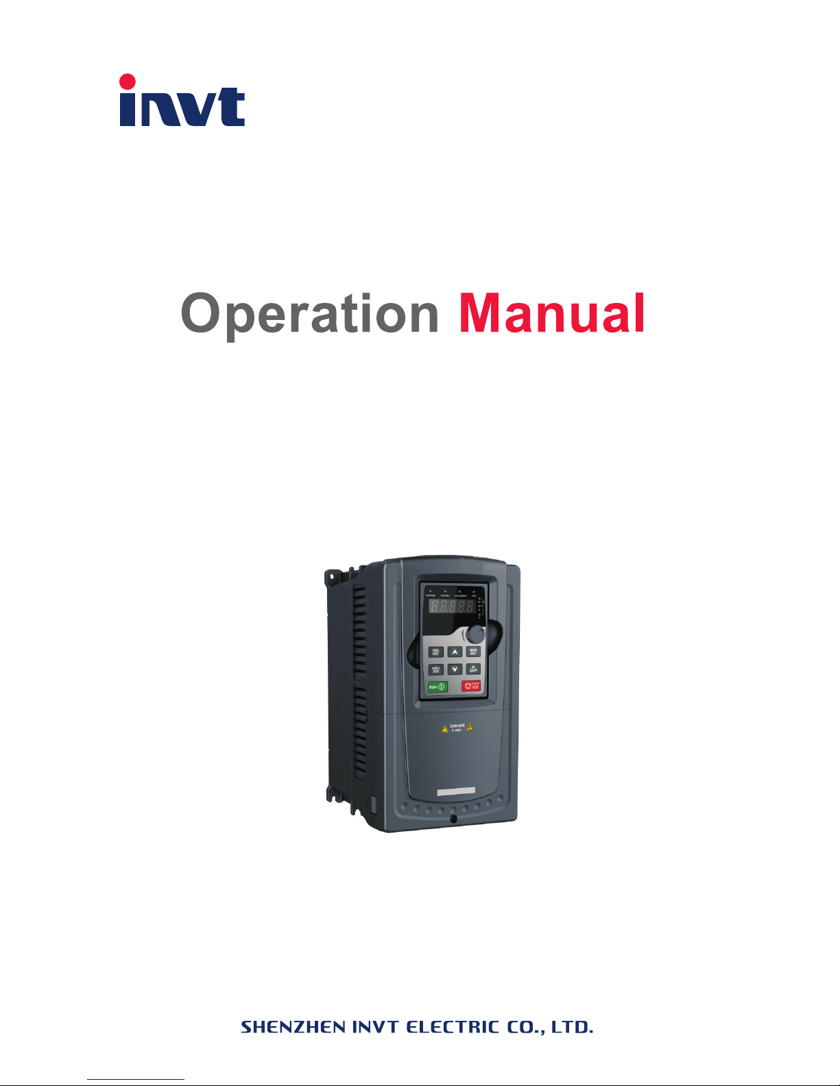
Goodrive300-16
Special Inver ter for HVAC
GD300-16-011G/015P-4
Page 2

Goodrive300-16 special inverter for HVAC Preface
1
Preface
Thanks for choosing our products.
Goodrive300-16 special inverters for HVAC are developed according to HVAC application
features and control requirements, and can be widely used in heating and water supply.
Applying TI 32bit DSP control system and the most advanced international SVC technology,
Goodrive300-16 inverters can meet the high performance requirements of customers.
Simultaneously, comparing with the other kinds, Goodrive300-16 inverters can adapt to
worse grid, temperature, humidity and dust with a better performance of anti-tripping and
improve the reliability. Goodrive300-16 inverters have safe and reliable fault protection
function, built-in realtime clock, two groups of PID adjusters and multi-motor combined
system and available BACnet communication, etc.
With EMC design, Goodrive300-16 inverters can meet the demand of environmental
protection which focuses on low noise and weakening electromagnetic interference in the
application sites for the customers.
This manual provides installation and configuration, parameters setting, fault diagnoses and
daily maintenance and relative precautions to customers. Please read this manual carefully
before the installation to ensure a proper installation and operation and high performance of
Goodrive300-16 inverters.
If the product is ultimately used for military affairs or manufacture of weapon, it will be listed
on the export control formulated by Foreign Trade Law of the People's Republic of China.
Rigorous review and necessary export formalities are needed when exported.
Our company reserves the right to update the information of our products.
Page 3

Goodrive300-16 special inverter for HVAC Content
2
Content
Preface .............................................................................................................................. 1
Content .............................................................................................................................. 2
Chapter 1 Safety precautions ................................ ............................................................. 3
1.1 What this chapter contains .................................................................................. 3
1.2 Safety definition .................................................................................................. 3
1.3 Warning symbols ................................................................................................ 3
1.4 Safety guidelines ................................................................................................ 4
Chapter 2 Product overview ............................................................................................... 7
2.1 Product specification ........................................................................................... 7
2.2 Name plate ......................................................................................................... 9
2.3 Type designation key .......................................................................................... 9
2.4 Rated specifications .......................................................................................... 10
Chapter 3 Commissioning guidelines ................................................................................. 11
3.1 Wiring of main circuit .......................................................................................... 11
3.2 Terminals of control circuit ................................................................................. 12
3.3 Wiring and commissioning of single fixed variable frequency motor+multiple power
frequency motors .................................................................................................... 15
3.4 Wiring and commissioning of multiple circulation variable frequency
motors+multiple power frequency motors ................................................................ 21
3.5 Commissioning instruction of extension functions .............................................. 27
3.6 Maintenance intervals ....................................................................................... 29
3.7 Fault instruction and solution ............................................................................. 32
Appendix A Function parameters .................................................................................... 39
A.1 Goodrive300-16 basic function parameters ....................................................... 39
A.2 Goodrive300-16 special function parameters .................................................. 108
A.3 Goodrive300-16 communication additions ...................................................... 124
Appendix B Dimension drawings .................................................................................. 126
B.1 Keypad structure and dimension ..................................................................... 126
B.2 Dimensions for wall installation ....................................................................... 127
B.3 Dimensions for flange installation ................................................................... 128
Appendix C Peripherial options and parts ..................................................................... 130
C.1 Breaker and electromagnetic contactor (optional) ........................................... 130
C.2 Reactors (optional) ......................................................................................... 131
C.3 Filter (optional) ............................................................................................... 132
Page 4
Goodrive300-16 special inverter for HVAC Safety precautions
3
Chapter 1 Safety precautions
1.1 What this chapter contains
Please read this manual carefully and follow all safety precautions before moving, installing,
operating and servicing the inverter. If ignored, physical injury or death may occur, or
damage may occur to the devices.
If any physical injury or death or damage to the devices occurs for ignoring to the safety
precautions in the manual, our company will not be responsible for any damages and we are
not legally bound in any manner.
1.2 Safety definition
Danger:
Serious physical injury or even death may occur if not follow
relevant requirements
Warning:
Physical injury or damage to the devices may occur if not follow
relevant requirements
Note:
Physical hurt may occur if not follow relevant requirements
Qualified
electricians:
People working on the device should take part in professional
electrical and safety training, receive the certification and be
familiar with all steps and requirements of installing,
commissioning, operating and maintaining the device to avoid any
emergency.
1.3 Warning symbols
Warnings caution you about conditions which can result in serious injury or death and/or
damage to the equipment, and advice on how to avoid the danger. Following warning
symbols are used in this manual:
Symbols
Name
Instruction
Abbreviation
Danger
Electrical
Danger
Serious physical injury or even
death may occur if not follow the
relative requirements
Warning
General
danger
Physical injury or damage to the
devices may occur if not follow the
relative requirements
Page 5
Goodrive300-16 special inverter for HVAC Safety precautions
4
Symbols
Name
Instruction
Abbreviation
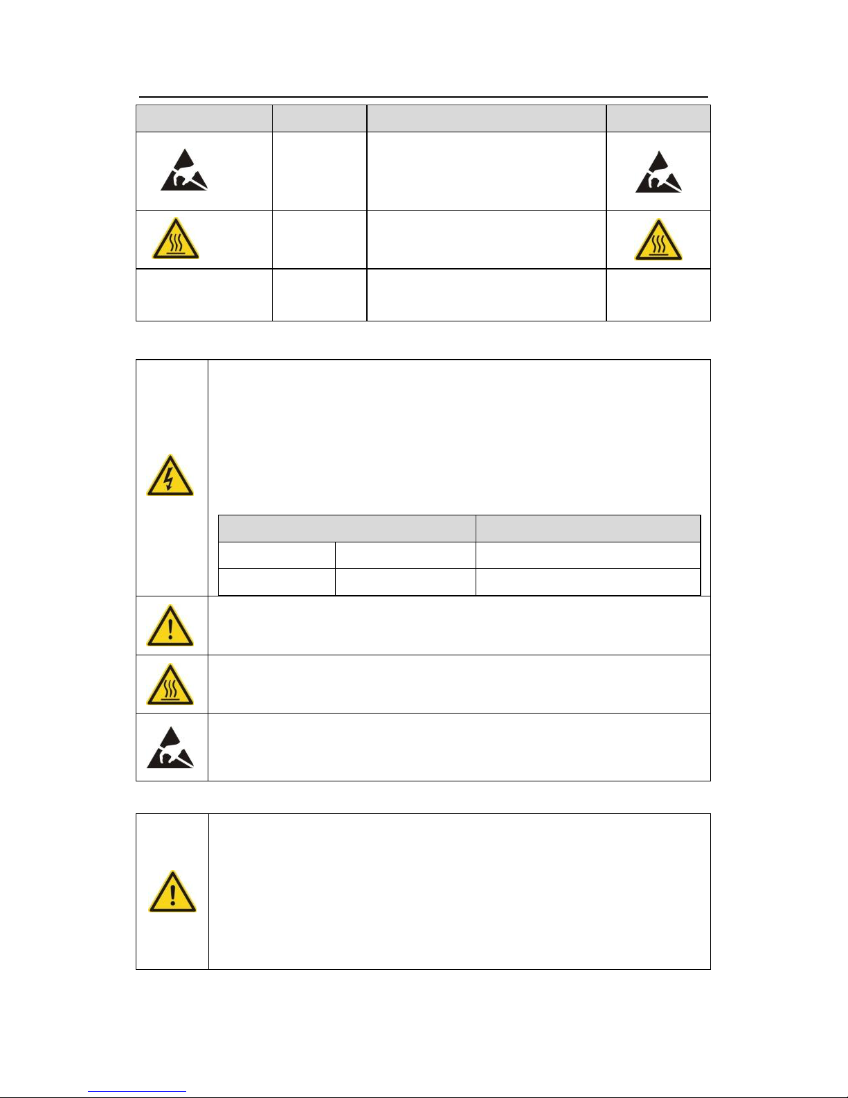
Do not
Electrostatic
discharge
Damage to the PCBA board may
occur if not follow the relative
requirements
Hot sides
Hot sides
Sides of the device may become
hot. Do not touch.
Note
Note
Physical hurt may occur if not follow
the relative requirements
Note
1.4 Safety guidelines
Only qualified electricians are allowed to operate on the inverter.
Do not carry out any wiring and inspection or changing components when the
power supply is applied. Ensure all input power supply is disconnected
before wiring and checking and always wait for at least the time designated
on the inverter or until the DC bus voltage is less than 36V. Below is the table
of the waiting time:
Inverter module
Minimum waiting time
380V
4kW-110kW
5 minutes
380V
132 kW
15 minutes
Do not refit the inverter unauthorizedly; otherwise fire, electric shock or other
injury may occur.
The base of the radiator may become hot during running. Do not touch to
avoid hurt.
The electrical parts and components inside the inverter are electrostatic. Take
measures to avoid electrostatic discharge during relevant operation.
1.4.1 Delivery and installation
Please install the inverter on fire-retardant material and keep the inverter
away from combustible materials.
Connect the braking optional parts (braking resistors, braking units or
feedback units) according to the wiring diagram.
Do not operate on the inverter if there is any damage or components loss to
the inverter.
Page 6
Goodrive300-16 special inverter for HVAC Safety precautions
5
Do not touch the inverter with wet items or body, otherwise electric shock
may occur.
Note:
Select appropriate moving and installing tools to ensure a safe and normal running of
the inverter and avoid physical injury or death. For physical safety, the erector should
take some mechanical protective measures, such as wearing exposure shoes and
working uniforms.
Ensure to avoid physical shock or vibration during delivery and installation.
Do not carry the inverter by its cover. The cover may fall off.
Install away from children and other public places.
The inverter cannot meet the requirements of low voltage protection in IEC61800-5-1
if the sea level of installation site is above 2000m.
Please use the inverter on appropriate condition (See chapter Installation
Environment).
Do not allow screws, cables and other conductive items to fall inside the inverter.
The leakage current of the inverter may be above 3.5mA during operation. High
leakage current, earth connection essential before connecting supply. Ground with
proper techniques and ensure the grounding resistor is less than 10Ω. The
conductivity of PE grounding conductor is the same as that of the phase conductor
(with the same cross sectional area).
R, S and T are the input terminals of the power supply, while U, V and W are the motor
terminals. Please connect the input power cables and motor cables with proper
techniques; otherwise the damage to the inverter may occur.
1.4.2 Commission and running
Disconnect all power supplies applied to the inverter before the terminal
wiring and wait for at least the designated time after disconnecting the
power supply.
High voltage is present inside the inverter during running. Do not carry
out any operation except for the keypad setting.
The inverter may start up by itself when P01.21=1. Do not get close to
the inverter and motor.
The inverter can not be used as “Emergency-stop device”.
The inverter can not be used to break the motor suddenly. A mechanical
braking device should be provided.
Page 7

Goodrive300-16 special inverter for HVAC Safety precautions
6
Note:
Do not switch on or off the input power supply of the inverter frequently.
For inverters that have been stored for a long time, check and fix the capacitance and
try to run it again before utilization (see Maintenance and Hardware Fault
Diagnose).
Cover the front board before running, otherwise electric shock may occur.
1.4.3 Maintenance and replacement of components
Only qualified electricians are allowed to perform the maintenance,
inspection, and components replacement of the inverter.
Disconnect all power supplies to the inverter before the terminal wiring.
Wait for at least the time designated on the inverter after disconnection.
Take measures to avoid screws, cables and other conductive matters to
fall into the inverter during maintenance and component replacement.
Note:
Please select proper torque to tighten screws.
Keep the inverter, parts and components away from combustible materials during
maintenance and component replacement.
Do not carry out any isolation and pressure test on the inverter and do not measure
the control circuit of the inverter by megameter.
Carry out a sound anti-electrostatic protection to the inverter and its internal
components during maintenance and component replacement.
1.4.4 What to do after scrapping
There are heavy metals in the inverter. Deal with it as industrial effluent.
Page 8

Goodrive300-16 special inverter for HVAC Product overview
7
Chapter 2 Product overview
Goodrive300-16 are special inverters for HVAC designed to solve the application problems
in HVAC industry, reduce the costs of customers, enhance the competitiveness and
guarantee for the advantages in HVAC industry. The products possess following features:
1. Built-in realtime clock for setting multiple events;
2. Built-in two groups of PID adjusters for various feedback sources;
3. Available various communication extension interfaces for customers, such as BACnet,
Profibus DP, DeviceNet and CANopen;
4. Extensible special relay extension board, available multi-motor power and variable
frequency switching start or power frequency start
2.1 Product specification
Function
Specification
Power
input
Input voltage (V)
3PH 380V(-15%)~440V(+10%)
Input current (A)
Refer to the rated value
Input frequency (Hz)
50Hz/60Hz
Allowed range: 47~63Hz
Power
output
Output voltage (V)
0~input voltage, error<5%
Output current (A)
Refer to the rated value
Output power (kW)
Refer to the rated value
Output frequency
(Hz)
0~400Hz
Running
control
feature
Control mode
V/F, sensorless vector control
Max. output
frequency
400Hz
Adjustable-speed
ratio
Open loop vector 1:100
Speed control
accuracy
±0.2% (sensorless vector control)
Speed fluctuation
± 0.3% (sensorless vector control)
Torque response
<20ms (sensorless vector control)
Torque control
accuracy
Open loop vector 10%
Page 9

Goodrive300-16 special inverter for HVAC Product overview
8
Function
Specification
PID function
2 sets of PID
Overload capability
G type: 150% of rated current: 60 seconds
180% of rated current: 10 seconds
200% of rated current: 1 second
P type: 120% of rated current: 60 seconds
Starting torque
0.3Hz 150% (sensorless vector control)
Protection function
More than 30 protection functions, including
overvoltage, overcurrent, overheating and phase
loss
Peripheral
interface
Analog input
2 0~10V/0~20mA and 1 -10~10V
Analog output
2 0~10V/0~20mA
Digital input
8 common inputs, the Max. frequency: 1kHz,
selectable PNP/NPN
1 high speed input, the Max. frequency: 50kHz
Digital output
2 programmable relay outputs, NO and NC;
1 high speed pulse output
Communication
Standard 485 interface, available RTU protocol
Communication
extension interface
Available Profibus DP, DeviceNet, BACnet and
CANopen
Relay extension card
6 programmable relay outputs, NO
Others
Mountable method
Wall and flange mountable
Temperature of the
running environment
-25~55℃, derate above 40℃, If temperature is
above 40℃, derate 1% for every additional 1℃.
Average non-fault
time
2 years (25℃ ambient temperature)
Protective degree
IP20
Safety
Meet CE requirements
Cooling
Forced air-cooling
DC reactor
Unavailable for 30kW and below, available for 37kW
above
EMC filter
Built-in C3 filters: meet the degree requirement of
IEC61800-3 C3
Page 10
Goodrive300-16 special inverter for HVAC Product overview
9
Function
Specification
Selectable C2 filters: meet the degree requirement
of IEC61800-3 C2
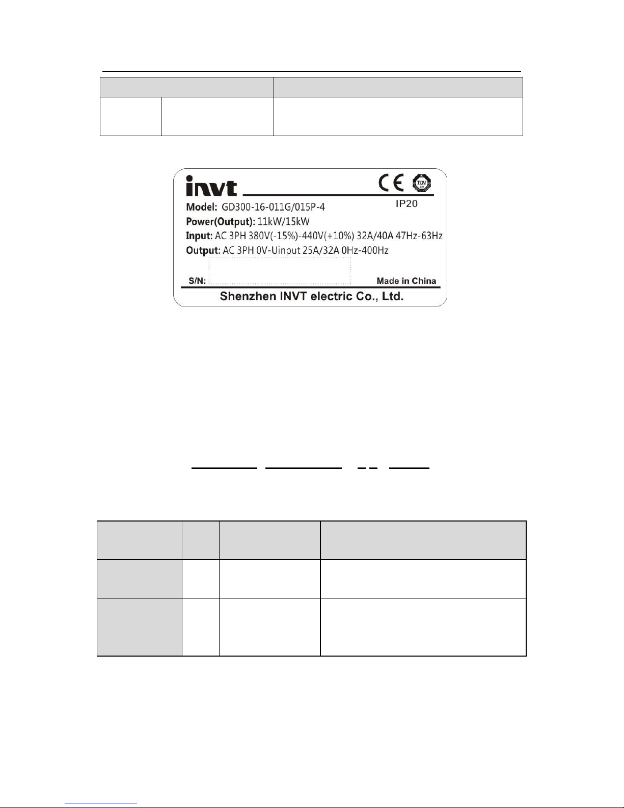
2.2 Name plate
Fig 2-1 Name plate
Note: The name plate above is an example of Goodrive300-16 standard products.
CE/TUV/IP20 will be identified on basis of actual certification.
2.3 Type designation key
The type designation contains information on the inverter. The user can find the type
designation on the type designation label attached to the inverter or the simple name plate.
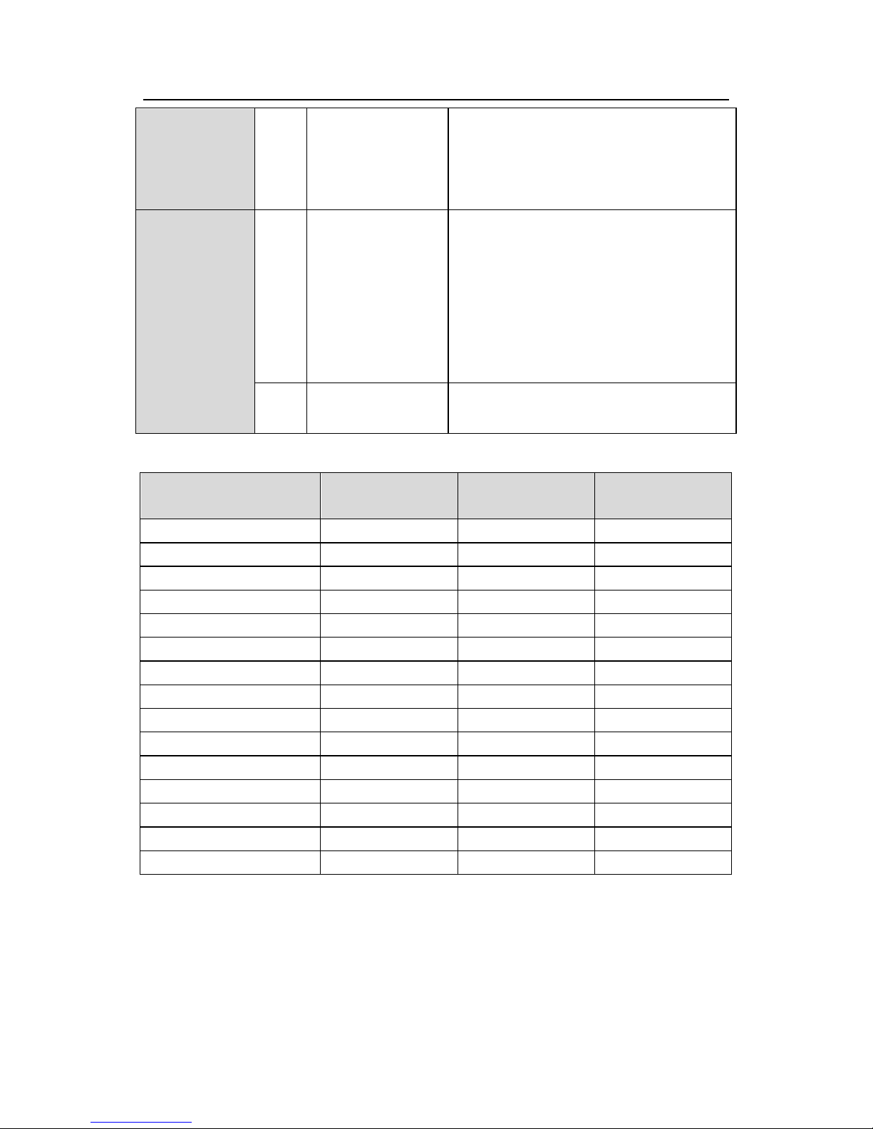
GD300-16–5R5G/7R5P – 4 1– HVAC
① ② ③ ④ ⑤
Fig 2-2 Product type
Key
No.
Detailed
description
Detailed content
Abbreviation
①
Product
abbreviation
GD300-16 is short for Goodrive300-16:
special for HVAC
Rated power
②
Power range +
Load type
5R5-5.5kW
G—Constant torque load
P—Variable torque load
Page 11
Goodrive300-16 special inverter for HVAC Product overview
10
Voltage
degree
③
Voltage degree
S2: AC 1PH 220V(-15%)~240V(+10%)
2: AC 3PH 220V(-15%)~240V(+10%)
4: AC 3PH 380V(-15%)~440V(+10%)
6: AC 3PH 520V(-15%)~690V(+10%)
Lot number
④
IP degree
Protective degree (the protective degree
of standard products can be default)
0-IP00;
1-IP20;
2-IP21;
5-IP54;
6-IP65;
⑤
Market lot number
HVAC: heating, ventilation and air
conditioning, can be omitted
2.4 Rated specifications
Model
Rated output
power(kW)
Rated input
current(A)
Rated output
current(A)
GD300-16-004G/5R5P-4
4/5.5
13.5/19.5
9.5/14
GD300-16-5R5G/7R5P-4
5.5/7.5
19.5/25
14/18.5
GD300-16-7R5G/011P-4
7.5/11
25/32
18.5/25
GD300-16-011G/015P-4
11/15
32/40
25/32
GD300-16-015G/018P-4
15/18.5
40/47
32/38
GD300-16-018G/022P-4
18.5/22
47/56
38/45
GD300-16-022G/030P-4
22/30
56/70
45/60
GD300-16-030G/037P-4
30/37
70/80
60/75
GD300-16-037G/045P-4
37/45
80/94
75/92
GD300-16-045G/055P-4
45/55
94/128
92/115
GD300-16-055G/075P-4
55/75
128/160
115/150
GD300-16-075G/090P-4
75/90
160/190
150/180
GD300-16-090G/110P-4
90/110
190/225
180/215
GD300-16-110G/132P-4
110/132
225/265
215/260
GD300-16-132G/160P-4
132/160
265/310
260/305
Note:
1. The input current of inverters 4~132kW is detected when the input voltage is 380V and
there is no DC reactors and input/output reactors.
2. The rated output current is defined when the output voltage is 380V.
3. The output current can not exceed the rated output current and the output power can not
exceed the rated output power in the voltage range.
Page 12
Goodrive300-16 special inverter for HVAC Commissioning guidelines
11
Chapter 3 Commissioning guidelines
3.1 Wiring of main circuit
R
S
T
W
V
U
PE
M
Inverters (≤30kW)
(+)
PB
Three-phase
380V(-15%)
~440V(+10%)
50/60Hz
Braking resistor
Input
reactor
Input
filter
Fuse
A1
A2
Single-phase 220V optional
Output
reactor
Output
filter
(-)
R
S
T
W
V
U
PE
M
Inverters (≥37kW)
P1
(+)
DC reactor
Three-phase
380V(-15%)
~440V(+10%)
50/60Hz
(-)
Fuse
A1
A2
DC-
Braking resistor
DC+
Braking unit
Single-phase 220V optional
Input
reactor
Input
filter
Output
reactor
Output
filter
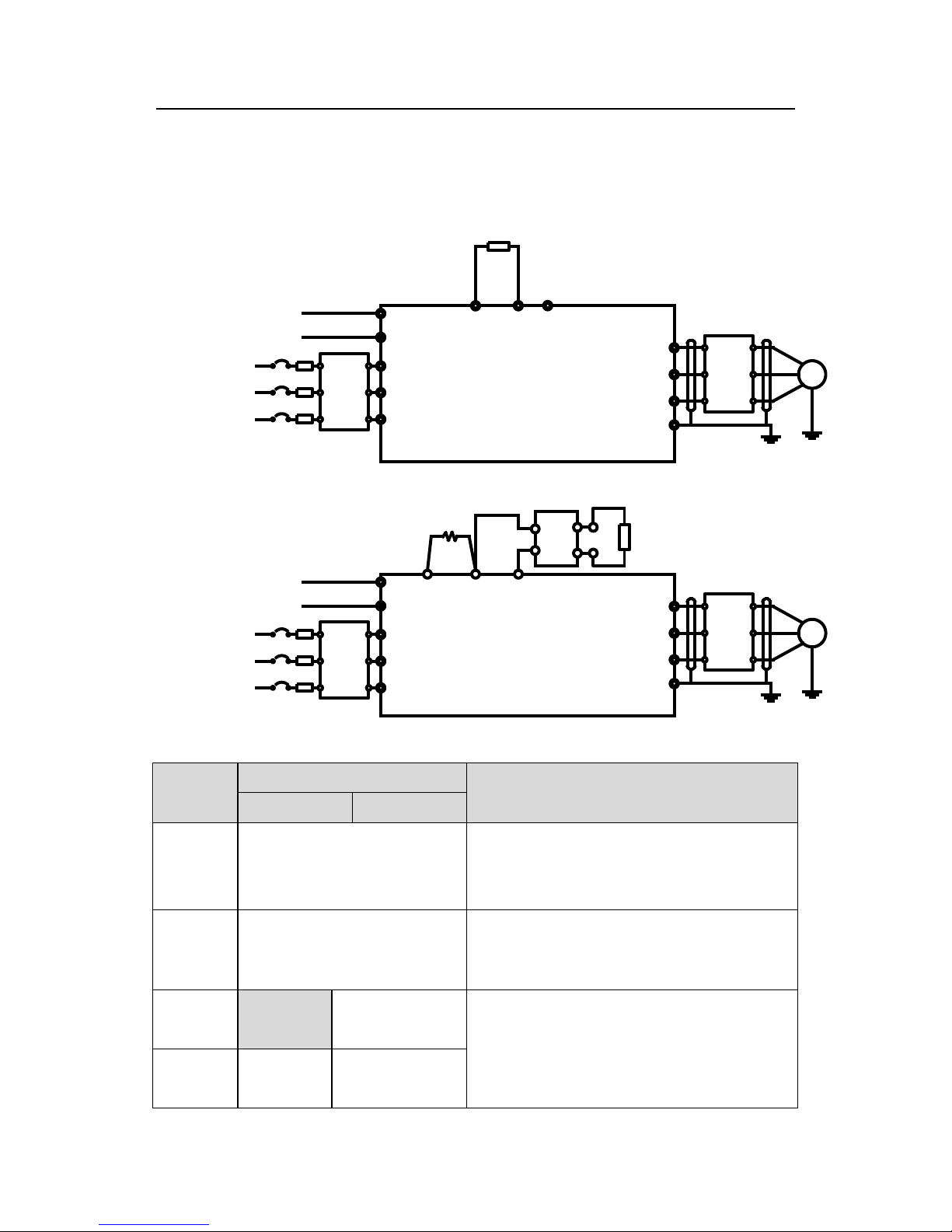
Fig 3-1 Wiring of main circuit
Terminal
Terminal name
Function
≤75kW
≥90kW
R,S,T
Power input of the main circuit
3-phase AC input terminals which are generally
connected with the power supply.
U,V,W
The inverter output
3-phase AC output terminals which are
generally connected with the motor.
P1
/
DC reactor
terminal 1
P1 and (+) are connected with the terminals of
DC reactor.
(+) and (-) are connected with the terminals of
braking unit.
(+)
Braking
resistor 1
DC reactor
terminal 2, braking
Page 13
Goodrive300-16 special inverter for HVAC Commissioning guidelines
12
Terminal
Terminal name
Function
≤75kW
≥90kW
unit terminal 1
PB and (+) are connected with the terminals of
braking resistor.
(-)
/
Braking unit
terminal 2
PB
Braking
resistor 2
/
PE
380V: the grounding resistor is
less than 10Ω
Protective grounding terminals, every machine
is provided 2 PE terminals as the standard
configuration. These terminals should be
grounded with proper techniques.
3.2 Terminals of control circuit
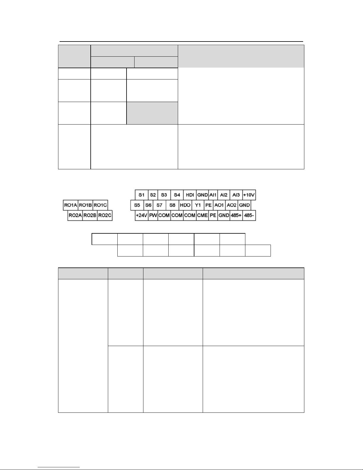
Fig 3-2 Terminals of control circuit
R03A
R03C
R04A
R04C
R05A
R05C
R06A
R06C
R07A
R07C
R08A
R08C
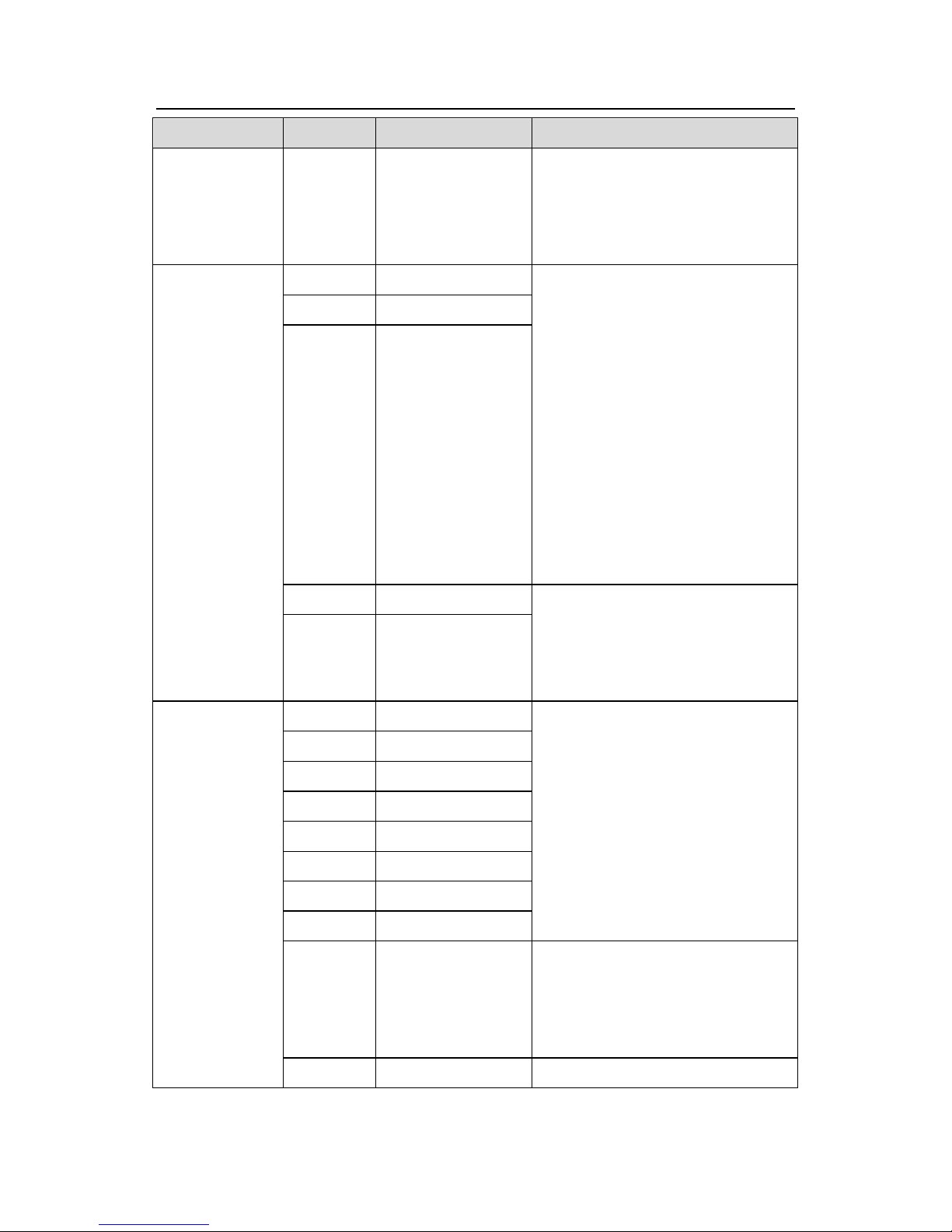
Fig 3-3 Relay extension board
Type
Code
Terminal name
Description
Power supply
+10V
10V reference
power supply
The inverter provides 10V
reference power supply with a
maximum output current of 50mA.
Generally as the power supply of
the external potentiometer with
resistance above 5kΩ
+24V
24V power supply
The inverter provides 24V±10%
power supply with a maximum
output current of 200mA.
Generally as the working power
supply of switch input and output or
the external sensor
Page 14
Goodrive300-16 special inverter for HVAC Commissioning guidelines
13
Type
Code
Terminal name
Description
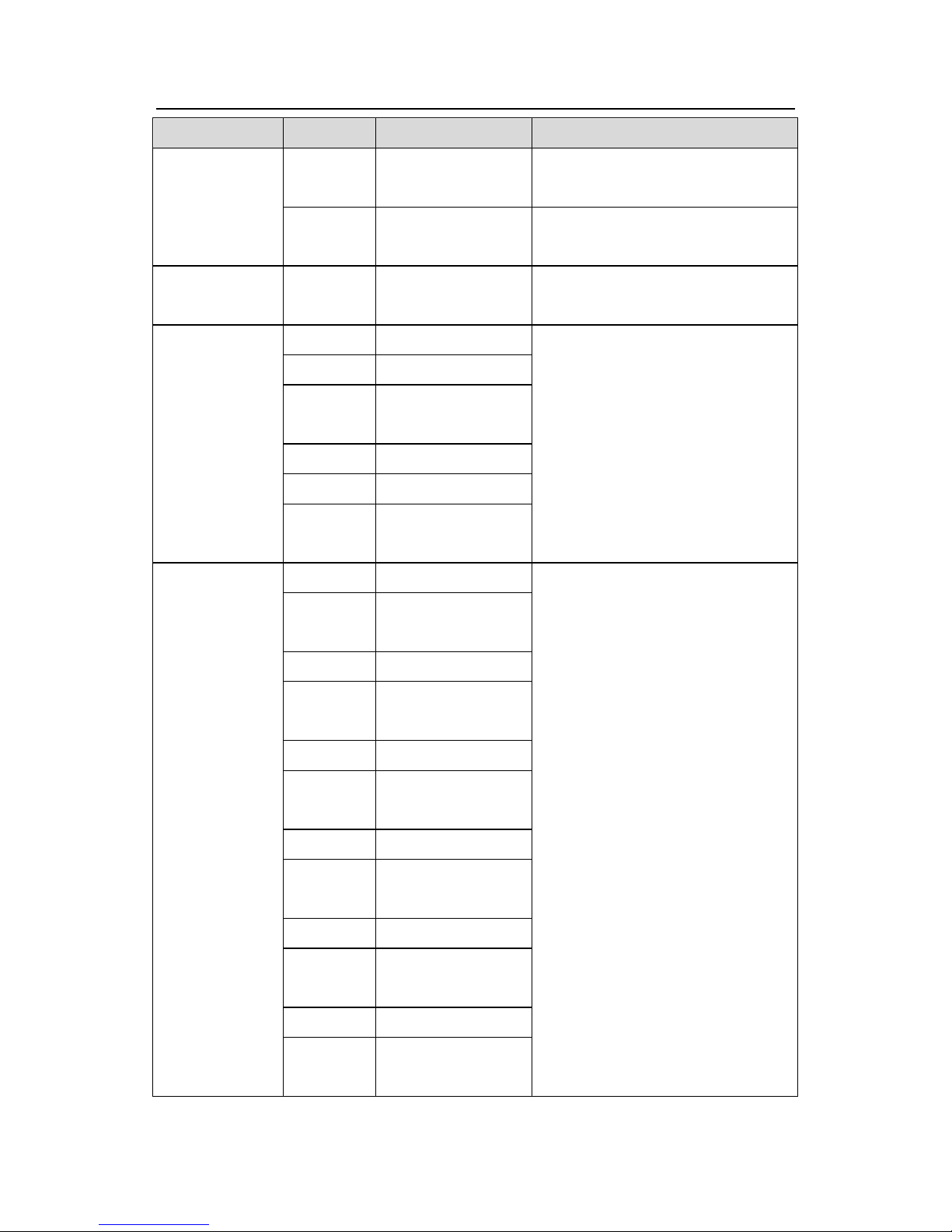
PW
External power
supply
Provide the input switch working
power supply from external to
internal.
Voltage range: 12~24V
Analog input
and output
AI1
Analog input 1
1. Input range: AI1/AI2 voltage and
current can be chosen
0~10V/0~20mA;
AI3:-10V~+10V
2. Input impedance: voltage input:
20kΩ; current input: 500Ω
3. The voltage or current input is
set by the jumper
4. Resolution: the minimum one is
5mV when 10V corresponds to
50Hz
AI2
Analog input 2
AI3
Analog input 3
AO1
Analog output 1
1. Output range: 0~10V or 0~20mA
2. The voltage or the current output
is set by the jumper
3. Resolution 10bit
AO2
Analog output 2
Switch input
and output
S1
Switch input 1
1. Internal impedance: 3.3kΩ
2. 12~30V voltage input is available
3. The terminal is the dual-direction
input terminal
4. Max. input frequency: 1kHz
S2
Switch input 2
S3
Switch input 3
S4
Switch input 4
S5
Switch input 5
S6
Switch input 6
S7
Switch input 7
S8
Switch input 8
HDI
Switch input
Except for S1~S8, this terminal can
be used as high frequency input
channel.
Max. input frequency: 50kHz
HDO
Switch output
1. Switch capacity: 50mA/30V
Page 15
Goodrive300-16 special inverter for HVAC Commissioning guidelines
14
Type
Code
Terminal name
Description
2. Output frequency range:
0~50kHz
Y1
Switch output
1. Switch capacity: 50mA/30V
2. Output frequency range: 0~1kHz
Communication
485+,485-
485
communication
485 communication terminal, adopt
MODBUS protocol
Relay output
RO1A
Relay 1 NO contact
Contact capacity: 3A/AC250V,
1A/DC30V
RO1B
Relay 1 NC contact
RO1C
Relay 1 common
contact
RO2A
Relay 2 NO contact
RO2B
Relay 2 NC contact
RO2C
Relay 2 common
contact
Relay output
(relay
extension
board)
RO3A
Relay 3 NO contact
Contact capacity: 3A/AC250V,
1A/DC30V
RO3C
Relay 3 common
contact
RO4A
Relay 4 NO contact
RO4C
Relay 4 common
contact
RO5A
Relay 5 NO contact
RO5C
Relay 5 common
contact
RO6A
Relay 6 NO contact
RO6C
Relay 6 common
contact
RO7A
Relay 7 NO contact
RO7C
Relay 7 common
contact
RO8A
Relay 8 NO contact
RO8C
Relay 8 common
contact
Page 16

Goodrive300-16 special inverter for HVAC Commissioning guidelines
15
3.3 Wiring and commissioning of single fixed variable frequency
motor+multiple power frequency motors
3.3.1 Standard wiring diagram
R
S
GD300-16
U
V
W
RO3
RO4
+10V
RO5
AI2
GND
AI1
GNDTPT
PID1
reference
PID1
feedback
M1
L1
L2
L3
KM1
M2
FR1
M3
KM2
FR2
M4
KM3
FR3
KM2 KM3
R04 R05
FR2 FR3
N
L1/L2/L3
KM1
R03
FR1
Note: The diagram is the system of the fixed variable frequency motor+3 power frequency
motors, which will become the system of single variable frequency motor without connecting
power frequency motors. Goodrive300-16 inverter can form the system of the fixed variable
frequency motor+8 power frequency motors.
3.3.2 Commissioning steps of basic functions
1. Check the circuits and ensure proper wiring;
2. P00.18=1, restore to factory default;
3. Input the parameters of motor name plate to P2 group and do motor autotuning;
4. P22.00=1, enable HVAC function;
5. P22.10=0, enable fixed variable frequency motor;
6. According to the actual situations, set multiple function codes of P22.11~P22.18 to 2 and
enable multiple power frequency motors;
7. According to the motor number, such as A and B, set P06 group;
8. Proper running and commissioning
Page 17
Goodrive300-16 special inverter for HVAC Commissioning guidelines
16
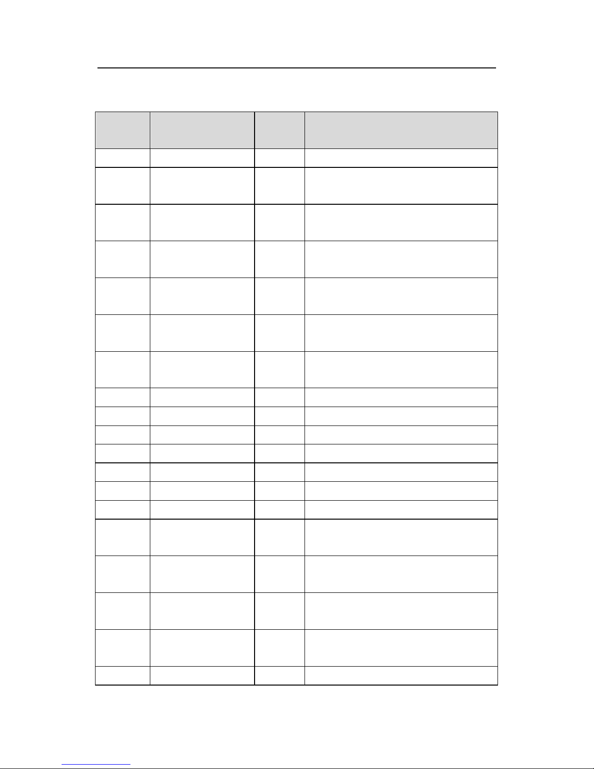
3.3.3 List of control parameters
List of relevant function parameters (take 3 power frequency motors for example)
Function
code
Name
Set
value
Remark
P00.00
Speed control mode
2
V/F control
P00.01
Run command
channel
1
Terminal control, adjustable according to
the actual situations
P00.03
Max. output
frequency
50.00Hz
Adjustable according to the actual
situations
P00.04
Upper limit of
running frequency
50.00Hz
Adjustable according to the actual
situations
P00.05
Lower limit of
running frequency
20.00Hz
Adjustable according to the actual
situations
P00.11
ACC time 1
4.0s
Adjustable according to the actual
situations
P00.12
DEC time 1
4.0s
Adjustable according to the actual
situations
P05.01
S1 terminals function
1
Forward running
P05.02
S2 terminals function
7
Fault reset
P06.03
Relay RO1 output
01
In running
P06.04
Relay RO2 output
05
Fault output signal
P06.05
Relay RO3 output
35
Connect motor A power frequency
P06.06
Relay RO4 output
37
Connect motor B power frequency
P06.07
Relay RO5 output
39
Connect motor C power frequency
P09.02
Max. PID1 reference
1.000
Adjustable according to the actual
situations
P09.03
Upper limit of PID1
reference
1.000
Adjustable according to the actual
situations
P09.04
Lower limit of PID1
reference
0.100
Adjustable according to the actual
situations
P09.05
PID1 reference
source 1
2
Adjustable according to the actual
situations
P09.09
ACC/DEC time of
0.000
Adjustable according to the actual
Page 18
Goodrive300-16 special inverter for HVAC Commissioning guidelines
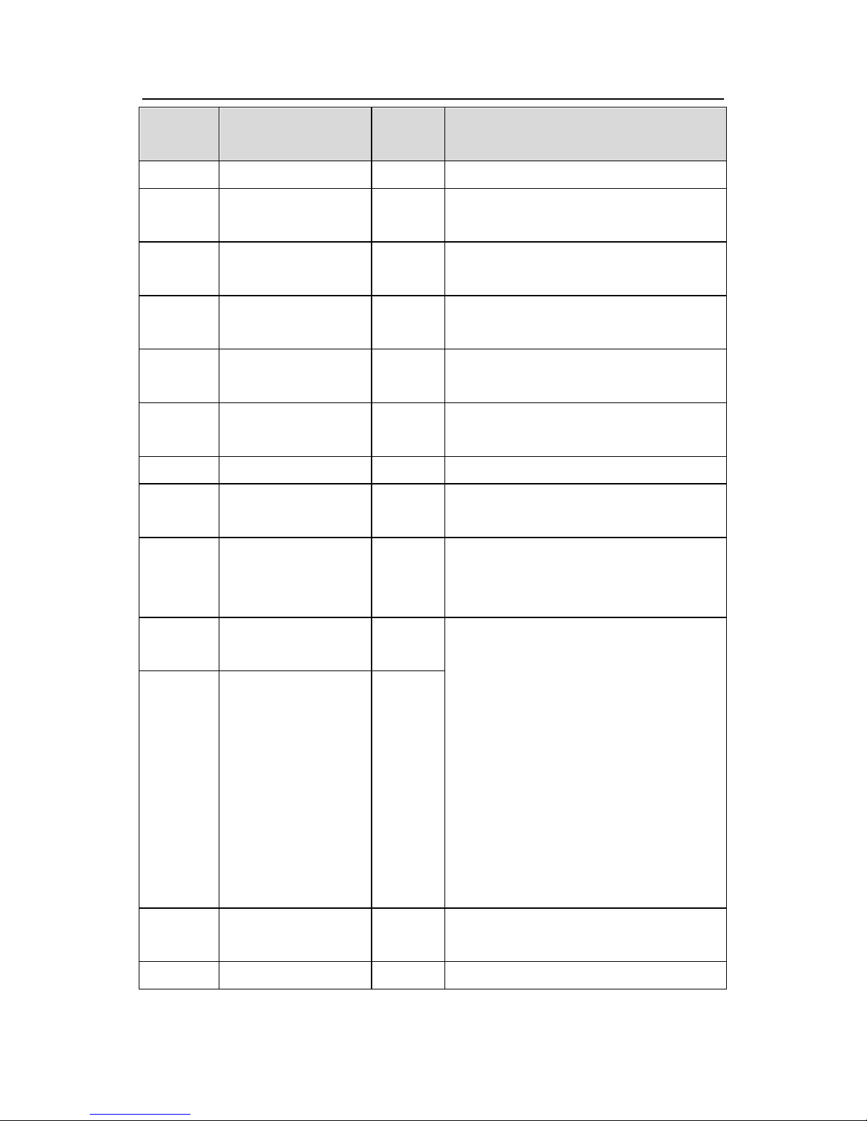
17
Function
code
Name
Set
value
Remark
PID1 reference
situations
P09.10
PID1 feedback
source 1
1
Adjustable according to the actual
situations
P09.16
Output feature
0
Adjustable according to the actual
situations
P09.17
Proportional gain
1.00
Adjustable according to the actual
situations
P09.18
Integral time
0.10
Adjustable according to the actual
situations
P09.19
Differential time
0.00
Adjustable according to the actual
situations
P22.00
HVAC function
1
HVAC function enabled
P22.01
Hibernation type
1
Hibernate according to the running
frequency
P22.02
Hibernation starting
frequency
40.00Hz
Allow hibernation only when the running
frequency is smaller than the value and
the hold time is larger than P22.04.
P22.03
Hibernation starting
deviation
5.0%
Relative to the maximum PID1 value
Allow hibernation only when the output
feature is positive, feedback is larger than
reference, the absolute value of the actual
deviation is larger than the value and the
hold time is larger than P22.04.
Allow hibernation only when the output
feature is negative, feedback is smaller
than reference, the absolute value of the
actual deviation is larger than the value
and the hold time is larger than P22.04.
P22.04
Hibernation entry
delay time
60.0s
P22.05
PID1 reference
boost
10.0%
Relative to PID1 reference
P22.06
Max. boost time
10.000s
Used to avoid the case where the inverter
Page 19

Goodrive300-16 special inverter for HVAC Commissioning guidelines
18
Function
code
Name
Set
value
Remark
runs continuously when the running
frequency reaches the upper limit while
the feedback cannot reach the set value
after boost, the inverter will enter
hibernation immediately after boost time.
P22.07
Hibernation waking
frequency
20.00Hz
PID output directly starts superposition
from the frequency when waking up in
close loop.
P22.08
Hibernation waking
deviation
2.0%
Relative to the maximum PID1 value
Allow waking up only when the output
feature is positive, feedback is smaller
than reference, the absolute value of the
actual deviation is larger than the value
and the hold time is larger than P22.09.
Allow waking up only when the output
feature is negative, feedback is larger
than reference, the absolute value of the
actual deviation is larger than the value
and the hold time is larger than P22.09.
P22.09
Hibernation waking
delay time
2.0s
Min. hibernation time
P22.10
Variable frequency
motor operation
0
Set to the fixed variable frequency motor,
invalid when A~H motors are set to
variable frequency motor, set to power
frequency motors when using multiple
motors
P22.11
A motor type
2
Power frequency motor
P22.12
B motor type
2
Power frequency motor
P22.13
C motor type
2
Power frequency motor
P22.19
Pressure allowance
when adding motor
4.0%
Adjustable according to the actual
situations
Page 20
Goodrive300-16 special inverter for HVAC Commissioning guidelines
19
Function
code
Name
Set
value
Remark
P22.20
Running frequency
when adding motor
50.00Hz
Adjustable according to the actual
situations
P22.21
Delay time when
adding motor
10.0s
Adjustable according to the actual
situations
P22.24
Pressure allowance
when reducing motor
4.0%
Adjustable according to the actual
situations
P22.25
Running frequency
when reducing motor
25.00Hz
Adjustable according to the actual
situations
P22.26
Delay time when
reducing motor
5.0s
Adjustable according to the actual
situations
P22.27
Action of variable
frequency motor
when reducing motor
0
Adjustable according to the actual
situations
P22.28
ACC time of variable
frequency motor
when reducing motor
10.0s
Adjustable according to the actual
situations
P22.29
Multi-motor pressure
loss compensation
0
Adjustable according to the actual
situations
P22.30
Pressure reference
boost value of 1
auxiliary motor
5.0%
Adjustable according to the actual
situations
P22.31
Pressure reference
boost value of 2
auxiliary motors
10.0%
Adjustable according to the actual
situations
P22.32
Pressure reference
boost value of 3
auxiliary motors
15.0%
Adjustable according to the actual
situations
P22.33
Circulation cycle of
power frequency
motor
24.0h
Adjustable according to the actual
situations
Page 21

Goodrive300-16 special inverter for HVAC Commissioning guidelines
20
3.3.4 Instruction of commissioning process
1. If the system of single variable frequency motor does not need the auxiliary power
frequency motor, set P22.11, P22.12 and P22.13 to 0. The system will proceed with close
loop PID adjustment, control the output frequency of the inverter and support P22.01 to
hibernate and wake up.
2. For the system of single variable frequency motor+multiple auxiliary power frequency
motors, set the parameters as above table and part of the parameters such as PID1
reference according to the actual situations. For the system of multi-motor in operation at the
same time, PID1 feedback detection value may be decreasing, then set P22.29=1 to boost
PID1 reference.
3. Generally, set P00.05 to non-zero and need to adjust the value according to the actual
situations. In the ACC/DEC stage, when the inverter has no fault, suggest setting P00.11
and P00.12 to smaller values such as in 3~5s to ensure PID adjustment has quick response.
4. P09.17 and P09.18 can be fine-tuned on the basis of factory values. If the actual
controlled quantity is over-tuned, set P09.19 properly and adjust according to the actual
situations.
5. The system of single variable frequency motor+multiple auxiliary power frequency motors
has logic functions of adding and reducing power frequency motors. Please refer to
Goodrive300-16 special function codes.
6. The system of single variable frequency motor+multiple auxiliary power frequency motors
supports P22.01 to hibernate and wake up only when the system reduces all power
frequency motors and the single variable frequency motor runs.
Page 22
Goodrive300-16 special inverter for HVAC Commissioning guidelines
21
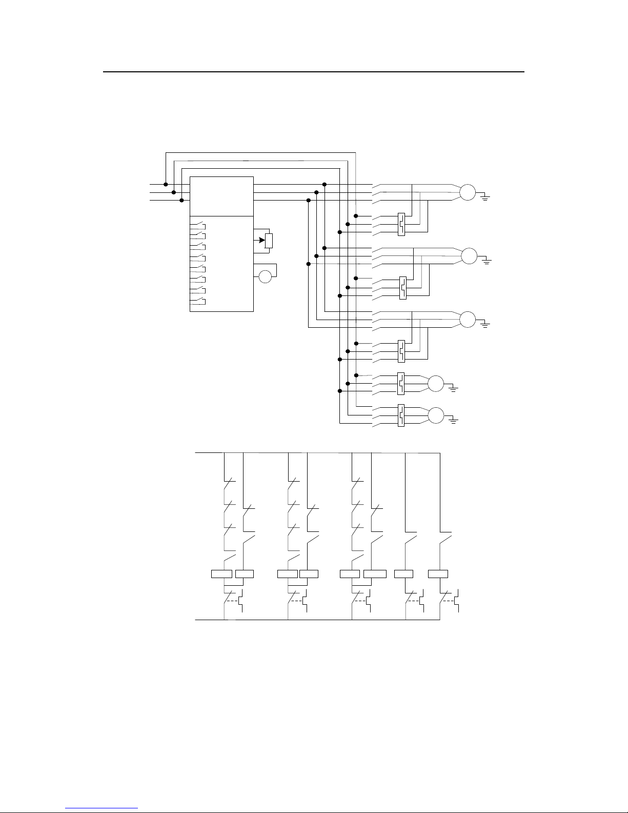
3.4 Wiring and commissioning of multiple circulation variable
frequency motors+multiple power frequency motors
3.4.1 Standard wiring diagram
R
S
GD300-16
U
V
W
RO1
RO6
RO2
+10V
RO3
RO4
RO5
AI2
GND
AI1
GNDTPT
PID1
reference
PID1
feedback
M1
L1
L2
L3
KM1
FR1
M4
KM6
FR4
M5
KM7
FR5
M2
KM3
FR2
M3
FR3
RO8
RO7
KM0
KM2
KM4
KM5
KM0
KM0 KM1
R01
R02
KM1
KM2
KM4
KM2
KM2 KM3
R03
R04
KM3
KM0
KM4
KM4
KM4 KM5
R05
R06
KM5
KM0
KM2
KM6 KM7
R07 R08
FR1 FR2 FR3 FR4 FR5
N
L1/L2/L3
Note: The diagram is the system of 3 circulation variable frequency motors+2 power
frequency motors, which will become the system of 3 circulation variable frequency motors
without connecting power frequency motors. Goodrive300-16 inverter can form the system
of 4 circulation variable frequency motors.
Page 23
Goodrive300-16 special inverter for HVAC Commissioning guidelines
22
3.4.2 Commissioning steps of basic functions
1. Check the circuits and ensure proper wiring;
2. P00.18=1, restore to factory default;
3. Input the parameters of motor name plate to P2 group and do motor autotuning;
4. P22.00=1, enable HVAC function;
5. P22.10=1, enable circulation variable frequency motor;
6. According to the actual situations, set multiple function codes of P22.11~P22.18 to 1 and
enable multiple circulation variable frequency motors; set the function codes to 2 and enable
power frequency motors;
7. According to the motor number, such as A and B, set P06 group;
8. Proper running and commissioning
3.4.3 List of control parameters
List of relevant function parameters (take 3 circulation variable frequency motors+2 power
frequency motors for example)
Function
code
Name
Set
value
Remark
P00.00
Speed control mode
2
V/F control
P00.01
Run command
channel
1
Terminal control, adjustable according to
the actual situations
P00.03
Max. output
frequency
50.00Hz
Adjustable according to the actual
situations
P00.04
Upper limit of
running frequency
50.00Hz
Adjustable according to the actual
situations
P00.05
Lower limit of
running frequency
20.00Hz
Adjustable according to the actual
situations
P00.11
ACC time 1
4.0s
Adjustable according to the actual
situations
P00.12
DEC time 1
4.0s
Adjustable according to the actual
situations
P05.01
S1 terminals function
1
Forward running
P05.02
S2 terminals function
7
Fault reset
P06.03
Relay RO1 output
34
Connect motor A variable frequency
P06.04
Relay RO2 output
35
Connect motor A power frequency
Page 24
Goodrive300-16 special inverter for HVAC Commissioning guidelines
23
Function
code
Name
Set
value
Remark
P06.05
Relay RO3 output
36
Connect motor B variable frequency
P06.06
Relay RO4 output
37
Connect motor B power frequency
P06.07
Relay RO5 output
38
Connect motor C variable frequency
P06.08
Relay RO6 output
39
Connect motor C power frequency
P06.09
Relay RO7 output
41
Connect motor D power frequency
P06.10
Relay RO8 output
43
Connect motor E power frequency
P09.02
Max. PID1 reference
1.000
Adjustable according to the actual
situations
P09.03
Upper limit of PID1
reference
1.000
Adjustable according to the actual
situations
P09.04
Lower limit of PID1
reference
0.100
Adjustable according to the actual
situations
P09.05
PID1 reference
source 1
2
Adjustable according to the actual
situations
P09.09
ACC/DEC time of
PID1 reference
0.000
Adjustable according to the actual
situations
P09.10
PID1 feedback
source 1
1
Adjustable according to the actual
situations
P09.16
Output feature
0
Adjustable according to the actual
situations
P09.17
Proportional gain
1.00
Adjustable according to the actual
situations
P09.18
Integral time
0.10
Adjustable according to the actual
situations
P09.19
Differential time
0.00
Adjustable according to the actual
situations
P22.00
HVAC function
1
HVAC function enabled
P22.01
Hibernation type
1
Hibernate according to the running
frequency
P22.02
Hibernation starting
frequency
40.00Hz
Allow hibernation only when the running
frequency is smaller than the value and
Page 25
Goodrive300-16 special inverter for HVAC Commissioning guidelines
24
Function
code
Name
Set
value
Remark
the hold time is larger than P22.04.
P22.03
Hibernation starting
deviation
5.0%
Relative to the maximum PID1 value
Allow hibernation only when the output
feature is positive, feedback is larger than
reference, the absolute value of the actual
deviation is larger than the value and the
hold time is larger than P22.04.
Allow hibernation only when the output
feature is negative, feedback is smaller
than reference, the absolute value of the
actual deviation is larger than the value
and the hold time is larger than P22.04.
P22.04
Hibernation entry
delay time
60.0s
P22.05
PID1 reference
boost
10.0%
Relative to PID1 reference
P22.06
Max. boost time
10.000s
Used to avoid the case where the inverter
runs continuously when the running
frequency reaches the upper limit while
the feedback cannot reach the set value
after boost, the inverter will enter
hibernation immediately after boost time.
P22.07
Hibernation waking
frequency
20.00Hz
PID output directly starts superposition
from the frequency when waking up in
close loop.
P22.08
Hibernation waking
deviation
2.0%
Relative to the maximum PID1 value
Allow waking up only when the output
feature is positive, feedback is smaller
than reference, the absolute value of the
actual deviation is larger than the value
and the hold time is larger than P22.09.
Allow waking up only when the output
feature is negative, feedback is larger
than reference, the absolute value of the
Page 26

Goodrive300-16 special inverter for HVAC Commissioning guidelines
25
Function
code
Name
Set
value
Remark
actual deviation is larger than the value
and the hold time is larger than P22.09.
P22.09
Hibernation waking
delay time
2.0s
Min. hibernation time
P22.10
Variable frequency
motor operation
1
Circulation variable frequency motor
P22.11
A motor type
1
Variable frequency motor
P22.12
B motor type
1
Variable frequency motor
P22.13
C motor type
1
Variable frequency motor
P22.14
D motor type
2
Power frequency motor
P22.15
E motor type
2
Power frequency motor
P22.19
Pressure allowance
when adding motor
4.0%
Adjustable according to the actual
situations
P22.20
Running frequency
when adding motor
50.00Hz
Adjustable according to the actual
situations
P22.21
Delay time when
adding motor
10.0s
Adjustable according to the actual
situations
P22.22
Switch frequency
when adding
variable frequency
motor
50.00Hz
Adjustable according to the actual
situations
P22.23
DEC time of variable
frequency motor
when adding power
frequency motor
10.0s
Adjustable according to the actual
situations
P22.24
Pressure allowance
when reducing motor
4.0%
Adjustable according to the actual
situations
P22.25
Running frequency
when reducing motor
25.00Hz
Adjustable according to the actual
situations
P22.26
Delay time when
reducing motor
5.0s
Adjustable according to the actual
situations
Page 27
Goodrive300-16 special inverter for HVAC Commissioning guidelines
26
Function
code
Name
Set
value
Remark
P22.27
Action of variable
frequency motor
when reducing motor
0
Adjustable according to the actual
situations
P22.28
ACC time of variable
frequency motor
when reducing motor
10.0s
Adjustable according to the actual
situations
P22.29
Multi-motor pressure
loss compensation
0
Adjustable according to the actual
situations
P22.30
Pressure reference
boost value of 1
auxiliary motor
5.0%
Adjustable according to the actual
situations
P22.31
Pressure reference
boost value of 2
auxiliary motors
10.0%
Adjustable according to the actual
situations
P22.32
Pressure reference
boost value of 3
auxiliary motors
15.0%
Adjustable according to the actual
situations
P22.33
Circulation cycle of
power frequency
motor
0.0h
Adjustable according to the actual
situations
P22.34
Circulation cycle of
variable frequency
motor
0.0h
Adjustable according to the actual
situations
P22.35
Circulation
frequency threshold
45.00Hz
Adjustable according to the actual
situations
3.4.4 Instruction of commissioning process
1. If the system of multiple circulation variable frequency motors does not need the auxiliary
power frequency motor, set P22.14 and P22.15 to 0. For the system of multiple circulation
variable frequency motors+multiple auxiliary power frequency motors, set the parameters as
above table and part of the parameters such as PID1 reference according to the actual
situations. For the system of multi-motor in operation at the same time, PID1 feedback
Page 28

Goodrive300-16 special inverter for HVAC Commissioning guidelines
27
detection value may be decreasing, then set P22.29=1 to boost PID1 reference.
2. Generally, set P00.05 to non-zero and need to adjust the value according to the actual
situations. In the ACC/DEC stage, when the inverter has no fault, suggest setting P00.11
and P00.12 to smaller values such as in 5s to ensure PID adjustment has quick response.
3. P09.17 and P09.18 can be fine-tuned on the basis of factory values. If the actual
controlled quantity is over-tuned, set P09.19 properly and adjust according to the actual
situations.
4. During adding and reducing motors, add variable frequency motors in priority if meeting
the conditions of adding motors; add power frequency motors if no variable frequency
motors. When the system of multi-motor in operation at the same time has only one motor in
variable frequency while others in power frequency and meets the conditions of reducing
motors, reduce power frequency motors until variable frequency motors are left. Please refer
to Goodrive300-16 special function codes.
5. The system of multiple circulation variable frequency motors+multiple auxiliary power
frequency motors supports P22.01 to hibernate and wake up only when the system reduces
all power frequency motors and the single variable frequency motor runs.
3.5 Commissioning instruction of extension functions
1. Realtime clock and timing function: Goodrive300-16 has built-in clock chip. After the
time is set to the chip, the current time and date can be observed on the inverter. The timing
function can be set according to the realtime time to control automatic start and stop of the
inverter. Refer to P21 group in Appendix A for detailed information.
2. Fire override function: Once there is any fire signal sent to the inverter, after the
program inside the inverter identifies the information, the motors will keep running in the set
fire frequency. Goodrive300-16 has 2 fire modes: fire mode 1: the inverter will keep running
all the time unless it is damaged; fire mode 2: the inverter will keep running all the time
except that it stops at OUT1, OUT2, OUT3, OC1, OC2, OC3, OV1, OV2, OV3 and SPO.
Refer to P21 group in Appendix A for detailed information.
3. Second set of PID adjustment function: Goodrive300-16 has built-in two sets of PID
adjusters. PID2 start or stop can be triggered by switch signals or current actual control
detection values. PID2 adjustment output values can be output to other masters via analog
or communication modes to control other functions. Refer to P21 group in Appendix A for
detailed information.
4. Detection function of water level of intake sump: Goodrive300-16 has built-in
Page 29

Goodrive300-16 special inverter for HVAC Commissioning guidelines
28
detection function of water level of intake sump for water supply applications. The inverter
receives the signals of water level of intake sump in real time. If the water level changes from
high to low, PID1 reference will be normal set value when the water level above lower limit;
PID1 reference will be P22.43 when the water level below lower limit and above water
shortage level; all water pumps of the control system will stop when the water level below
water shortage level. If the water level changes from low to high, the system will stop when
the water level below lower limit; PID1 reference will be P22.43 when the water level below
upper limit and above lower limit; PID1 reference will be normal set value when the water
level above upper limit.
5. Abnormal PID1 feedback pre-alarm function: Goodrive300-16 has built-in abnormal
PID1 feedback detection pre-alarm function. The inverter receives feedback signals in real
time. If PID1 feedback is P22.45 and no more than P22.44, the inverter will display “-LP-”
indicating PID1 feedback is too low. If PID1 feedback is P22.47 and no less than P22.46, the
inverter will display “-HP-” indicating PID1 feedback is too high. Press PRG/ESC key to
return to stop or run displaying interface and other keys are invalid. If PID1 feedback is
normal, return to stop or run displaying interface automatically.
6. Multi-motor manual start test function: The manual start test function consists of
manual soft start and manual circulation.
The manual soft start is only valid for circulation variable frequency motors and needs fitting
with the terminal corresponding to the function of the motors. When the manual soft start and
the signal of manual soft start of variable frequency motors are valid, the inverter will control
the motor to start and run to P22.38, then coast to stop and connect the motor to power
frequency power. If the corresponding S terminal of the motor is invalid, stop immediately. If
the corresponding terminal of manual soft commissioning command is invalid, all motors will
stop immediately.
When the manual circulation signal is valid, the circulation process for power frequency
motors: connect the motor to power frequency power supply and disconnect the power
supply after running a certain time, repeat with the second valid motor and so on. When the
manual circulation signal is valid, the circulation process for variable frequency motors: start
operating the motor in switch frequency P22.22, control the inverter to coast to stop after
running a certain time, then connect the motor to power frequency power supply and
disconnect the power supply after running a certain time, repeat with the second valid motor
and so on. All motors under power frequency and variable frequency will stop only when the
manual circulation signal is invalid.
Page 30

Goodrive300-16 special inverter for HVAC Commissioning guidelines
29
7. HVAC check function: The running conditions of the motors, PID1 and PID2 running
states and relevant output values can be checked out in P18 group. The function facilitates
analyzing and adjusting function parameters.
3.6 Maintenance intervals
If installed in an appropriate environment, the inverter requires very little maintenance. The
table lists the routine maintenance intervals recommended by INVT.
Checking
Item
Method
Criterion
Ambient
environment
Check the ambient
temperature, humidity and
vibration and ensure there is
no dust, gas, oil fog and
water drop.
Visual examination
and instrument test
Conforming to the
manual
Ensure there are no tools or
other foreign or dangerous
objects
Visual examination
There are no tools
or dangerous
objects.
Voltage
Ensure the main circuit and
control circuit are normal.
Measurement by
millimeter
Conforming to the
manual
Keypad
Ensure the display is clear
enough
Visual examination
The characters
are displayed
normally.
Ensure the characters are
displayed totally
Visual examination
Conforming to the
manual
Main
circuit
For
public
use
Ensure the screws are
tightened securely
Tighten up
NA
Ensure there is no distortion,
crackles, damage or
color-changing caused by
overheating and aging to the
machine and insulator.
Visual examination
NA
Ensure there is no dust and
dirtiness
Visual examination
NA
Note: if the color
of the copper
blocks change, it
Page 31
Goodrive300-16 special inverter for HVAC Commissioning guidelines
30
Checking
Item
Method
Criterion
does not mean
that there is
something wrong
with the features.
The
lead
of the
conductors
Ensure that there is no
distortion or color-changing
of the conductors caused by
overheating.
Visual examination
NA
Ensure that there are no
crackles or color-changing of
the protective layers.
Visual examination
NA
Terminals
seat
Ensure that there is no
damage
Visual examination
NA
Filter
capacitors
Ensure that there is no
weeping, color-changing,
crackles and casing
expansion.
Visual examination
NA
Ensure the safety valve is in
the right place.
Estimate the usage
time according to the
maintenance or
measure the static
capacity.
NA
If necessary, measure the
static capacity.
Measure the
capacity by
instruments.
The static capacity
is above or equal
to the original
value *0.85.
Resistors
Ensure whether there is
displacement caused by
overheating.
Smelling and visual
examination
NA
Ensure that there is no
offline.
Visual examination
or remove one
ending to coagulate
The resistors are
in ±10% of the
standard value.
Page 32

Goodrive300-16 special inverter for HVAC Commissioning guidelines
31
Checking
Item
Method
Criterion
or measure with
multimeters
Transforme
rs
and
reactors
Ensure there is no abnormal
vibration, noise and smelling,
Hearing, smelling
and visual
examination
NA
Electroma
gnetism
contactors
and
relays
Ensure whether there is
vibration noise in the
workrooms.
Hearing
NA
Ensure the contact is good
enough.
Visual examination
NA
Control
circuit
PCB
and
plugs
Ensure there are no loose
screws and connectors.
Fasten up
NA
Ensure there is no smelling
and color-changing.
Smelling and visual
examination
NA
Ensure there are no
crackles, damage, distortion
and rust.
Visual examination
NA
Ensure there is no weeping
and distortion to the
capacitors.
Visual examination
or estimate the
usage time
according to the
maintenance
information
NA
Cooling
system
Cooling
fan
Estimate whether there is
abnormal noise and
vibration.
Hearing and Visual
examination or
rotate with hand
Stable rotation
Estimate there is no loose
screw.
Tighten up
NA
Ensure there is no
color-changing caused by
overheating.
Visual examination
or estimate the
usage time
NA
Page 33

Goodrive300-16 special inverter for HVAC Commissioning guidelines
32
Checking
Item
Method
Criterion
according to the
maintenance
information
Ventilating
duct
Ensure whether there is no
stuff or foreign objects in the
cooling fan and air vent.
Visual examination
NA
Consult the local service representative for more details on the maintenance. Visit the official
website.
3.7 Fault instruction and solution
Do as the following after the inverter fault:
1. Check to ensure there is nothing wrong with the keypad. If not, please contact with the
local INVT office.
2. If there is nothing wrong, please check P07 and ensure the corresponding recorded fault
parameters to confirm the real state when the current fault occurs by all parameters.
3. See the following table for detailed solution and check the corresponding abnormal state.
4. Eliminate the fault and ask for relative help.
5. Check to eliminate the fault and carry out fault reset to run the inverter.
Code
Fault
Cause
Solution
OUt1
IGBT U phase
protection
The acceleration is too fast
There is damage to the
internal to IGBT of the phase
The connection of the driving
wires is not good
The grounding is not good
Increase ACC time
Change the power unit
Check the driving wires
Check if there is strong
interference to the external
equipment
OUt2
IGBT V phase
protection
OUt3
IGBT W
phase
protection
OC1
Accelerating
overcurrent
The acceleration or
deceleration is too fast
The voltage of the grid is too
low
The power of the inverter is
too low
The load transients or is
Increase the ACC time
Check the input power
Select the inverter with a larger
power
Check if the load is short
circuited (the grounding short
circuited or the wire short
OC2
Decelerating
overcurrent
OC3
Constant
overcurrent
Page 34
Goodrive300-16 special inverter for HVAC Commissioning guidelines
33
Code
Fault
Cause
Solution
abnormal
The grounding is short
circuited or the output is
phase loss
There is strong external
interference
circuited) or the rotation is not
smooth
Check the output configuration.
Check if there is strong
interference
OV1
Accelerating
overvoltage
The input voltage is
abnormal
There is large energy
feedback
Check the input power
Check if the DEC time of the
load is too short or the inverter
starts during the rotation of the
motor or it needs to increase the
energy consumption
components
OV2
Decelerating
overvoltage
OV3
Constant
overvoltage
UV
Bus
undervoltage
fault
The voltage of the power
supply is too low
Check the input power of the
supply line
OL1
Motor
overload
The voltage of the power
supply is too low
The motor setting rated
current is incorrect
The motor stall or load
transients is too strong
Check the power of the supply
line
Reset the rated current of the
motor
Check the load and adjust the
torque lift
OL2
Inverter
overload
The acceleration is too fast
Reset the rotating motor
The voltage of the power
supply is too low.
The load is too heavy.
The motor power is too
small.
Increase the ACC time
Avoid the restarting after
stopping.
Check the power of the supply
line
Select an inverter with bigger
power.
Select a proper motor.
SPI
Input phase
loss
Phase loss or fluctuation of
input R,S,T
Check input power
Check installation distribution
Page 35
Goodrive300-16 special inverter for HVAC Commissioning guidelines
34
Code
Fault
Cause
Solution
SPO
Output phase
loss
U,V,W phase loss input(or
serious asymmetrical three
phase of the load)
Check the output distribution
Check the motor and cable
OH1
Rectifying
module
overheated
Air duct jam or fan damage
Ambient temperature is too
high.
The time of overload running
is too long.
Refer to the overcurrent solution
Redistribute dredge the wind
channel or change the fan
Low the ambient temperature
Check and reconnect
Change the power
Change the power unit
Change the main control panel
OH2
IGBT
overheated
EF
External fault
SI external fault input
terminals action
Check the external device input
CE
485
communication
fault
The baud rate setting is
incorrect.
Fault occurs to the
communication wiring.
The communication address
is wrong.
There is strong interference
to the communication.
Set proper baud rate
Check the communication
connection distribution
Set proper communication
address.
Chang or replace the connection
distribution or improve the
anti-interference capability.
ItE
Current-detect
ing fault
The connection of the control
board is not good
Assistant power is bad
Hoare components is broken
The modifying circuit is
abnormal.
Check the connector and
repatch
Change the Hoare
Change the main control panel
tE
Motor-autotun
ing fault
The motor capacity does not
comply with the inverter
capability
The rated parameter of the
motor does not set correctly.
Change the inverter mode
Set the rated parameter
according to the motor name
plate
Empty the motor load and
Page 36
Goodrive300-16 special inverter for HVAC Commissioning guidelines
35
Code
Fault
Cause
Solution
The offset between the
parameters from autotune
and the standard parameter
is huge
Autotune overtime
reidentify
Check the motor connection and
set the parameter.
Check if the upper limit
frequency is above 2/3 of the
rated frequency.
EEP
EEPROM
operation fault
Error of controlling the write
and read of the parameters
Damage to EEPROM
Press STOP/RST to reset
Change the main control panel
bCE
Braking unit
fault
Braking circuit fault or
damage to the braking pipes
The external braking resistor
is not sufficient
Check the braking unit and ,
change new braking pipe
Increase the braking resistor
END
Running time
arrival
The actual running time of
the inverter is above the
internal setting running time.
Ask for the supplier and adjust
the setting running time.
OL3
Electrical
overload
The inverter will report
overload pre-alarm
according to the set value.
Check the load and the overload
pre-alarm point.
PCE
Keypad
communication
fault
The connection of the
keypad wires is not good or
broken.
The keypad wire is too long
and affected by strong
interference.
There is circuit fault on the
communication of the
keypad and main board.
Check the keypad wires and
ensure whether there is mistake.
Check the environment and
avoid the interference source.
Change the hardware and ask
for service.
UPE
Parameters
uploading
fault
The connection of the
keypad wires is not good or
broken.
The keypad wire is too long
Check the keypad wires and
ensure whether there is mistake.
Change the hardware and ask
for service.
Page 37
Goodrive300-16 special inverter for HVAC Commissioning guidelines
36
Code
Fault
Cause
Solution
and affected by strong
interference.
Communication fault.
Change the hardware and ask
for service.
DNE
Parameters
downloading
fault
The connection of the
keypad wires is not good or
broken.
The keypad wire is too long
and affected by strong
interference.
There is mistake on the data
storage of the keypad.
Check the keypad wires and
ensure whether there is mistake.
Change the hardware and ask
for service.
Repack-up the data in the
keypad.
ETH1
Grounding
shortcircuit
fault 1
The output of the inverter is
short circuited with the
ground.
There is fault in the current
detection circuit.
The actual motor power
sharply differs from the
inverter power.
Check if the connection of the
motor is normal or not
Change the hoare
Change the main control panel
Set motor parameters correctly.
ETH2
Grounding
shortcircuit
fault 2
The output of the inverter is
short circuited with the
ground.
There is fault in the current
detection circuit.
The actual motor power
sharply differs from the
inverter power.
Check if the connection of the
motor is normal or not
Change the Hoare
Change the main control panel
Set motor parameters correctly.
dEv
Speed
deviation fault
The load is too heavy or
stalled.
Check the load and ensure it is
normal. Increase the detection
time.
Check whether the control
parameters are normal.
STo
Maladjustment
The control parameters of
Check the load and ensure it is
Page 38
Goodrive300-16 special inverter for HVAC Commissioning guidelines
37
Code
Fault
Cause
Solution
fault
the synchronous motors not
set properly.
The autotuning parameter is
not right.
The inverter is not connected
to the motor.
normal.
Check whether the control
parameter is set properly or not.
Increase the maladjustment
detection time.
LL
Electronic
underload
fault
The inverter will report the
underload pre-alarm
according to the set value.
Check the load and the
underload pre-alarm point.
PId1E
Feedback
over limit fault
PID1 feedback value is
larger than upper limit
detection value or smaller
than lower limit detection
value in a long time.
Check PID1 feedback source;
Check PID1 feedback source
signal connection
TI-E
Clock chip
fault
The slot terminal board is
loose.
EEPROM is broken
Check the slot terminal board;
Press STOP/RST to reset;
Change the main control board
E-DP
Profibus-DP
communication
fault
Communication address is
not correct.
Corresponding resistor is not
dialed
The files of main stop GSD
does not set sound
The ambient interference is
too strong.
Check related setting
Check the communication
method selection.
Check the environment and
avoid the interference.
E-NET
Ethernet
communication
fault
The Ethernet address is not
set right.
The Ethernet communication
is not selected to right.
The ambient interference is
too strong.
Check the relative setting.
Check the communication
method selection.
Check the environment and
avoid the interference.
E-CAN
CANopen
The connection is not sound
Check the connection
Page 39

Goodrive300-16 special inverter for HVAC Commissioning guidelines
38
Code
Fault
Cause
Solution
communication
fault
Corresponding resistor is not
dialed
The communication baud
rate is uneven
The ambient interference is
too strong.
Draw out the correspond resistor
Set the same baud rate
Check the environment and
avoid the interference.
E-DP
BACnet
communication
fault
The Ethernet communication
is not selected to right.
The ambient interference is
too strong.
Check the communication
method selection.
Check the environment and
avoid the interference.
E-CAN
Devicenet
communication
fault
The connection is not sound
The communication baud
rate is uneven
The ambient interference is
too strong.
Check the connection
Set the same baud rate
Check the environment and
avoid the interference.
HP
Low PID1
feedback
pre-alarm
Inverter
non-stop fault
PID1 feedback value
continues P22.45 and is
smaller than P22.44
Check PID1 actual feedback
value is normal
Check PID1 feedback detection
device has no fault
LP
High PID1
feedback
pre-alarm
Inverter
non-stop fault
PID1 feedback value
continues P22.47 and is
larger than P22.46
Check PID1 actual feedback
value is normal
Check PID1 feedback detection
device has no fault
Page 40
Goodrive300-16 special inverter for HVAC Appendix A
39
Appendix A Function parameters
For the convenience of function codes setting, the function group number corresponds to the
first level menu, the function code corresponds to the second level menu and the function
code parameter corresponds to the third level menu.
Below is the instruction of the function lists:
The first line “Function code”: codes of function parameter group and parameters;
The second line “Name”: full name of function parameters;
The third line “Detailed instruction of parameters”: detailed instruction of the function
parameters;
The fourth line “Default value”: the original factory values of the function parameter;
The fifth line “Modify”: the modifying character of function codes (the parameters can be
modified or not and the modifying conditions), below is the instruction:
“○”: means the set value of the parameter can be modified on stop and running state;
“◎”: means the set value of the parameter can not be modified on the running state;
“●”: means the value of the parameter is the real detection value which can not be
modified.
(The inverter has limited the automatic inspection of the modifying character of the
parameters to help users avoid mismodifying)
A.1 Goodrive300-16 basic function parameters
Function
code
Name
Detailed instruction of parameters
Default
value
Modify
P00 Group Basic function group
P00.00
Speed
control
mode
0: Sensorless vector control mode 0
1: Sensorless vector control mode 1
2: V/F control
Note: Only apply to asynchronous motors
2
◎
P00.01
Run
command
channel
0: Keypad running command
1: Terminal running command channel
2: Communication running command channel
0
○
P00.02
Communic
ation
running
commands
0: MODBUS communication channel
1: Profibus/CANopen/BACnet/Devicenet
communication channel
2: Ethernet communication channel
0
○
Page 41
Goodrive300-16 special inverter for HVAC Appendix A
40
Function
code
Name
Detailed instruction of parameters
Default
value
Modify
3:Reserved
Note: 1, 2 and 3 are extension functions which
need corresponding extension cards.
P00.03
Max. output
frequency
Max. (P00.04, 10.00)~400.00Hz
50.00Hz
◎
P00.04
Upper limit
of running
frequency
P00.05~P00.03 (Max. output frequency)
50.00Hz
◎
P00.05
Lower limit
of running
frequency
0.00Hz~P00.04 (Upper limit of running frequency)
0.00Hz
◎
P00.06
A
frequency
command
0: Keypad
1: AI1
2: AI2
3: AI3
4: High-speed pulse HDI setting
5: Simple PLC program setting
6: Multi-step speed running setting
7: PID1 control setting
8: MODBUS communication setting
9: Profibus/CANopen/BACnet/Devicenet
communication setting
10: Ethernet communication setting
11: Reserved
0
○
P00.07
B
frequency
command
2
○
P00.08
B
frequency
command
reference
0: Maximum output frequency
1: A frequency command
0
○
P00.09
Combination
of setting
source
0: A
1: B
2: A+B
3: A-B
4: Max (A, B)
5: Min (A, B)
0
○
Page 42

Goodrive300-16 special inverter for HVAC Appendix A
41
Function
code
Name
Detailed instruction of parameters
Default
value
Modify
P00.10
Keypad set
frequency
0.00 Hz~P00.03 (Max. output frequency)
50.00Hz
○
P00.11
ACC time 1
0.0~3600.0s
Depend
on
model
○
P00.12
DEC time 1
0.0~3600.0s
Depend
on
model
○
P00.13
Running
direction
0: Runs at the default direction
1: Runs at the reverse direction
0
○
P00.14
Carrier
frequency
setting
1.0~15.0kHz
Depend
on
model
○
P00.15
Motor
parameter
autotuning
0: No operation
1: Rotation autotuning
2: Static autotuning 1(autotune totally)
3: Static autotuning 2(autotune part parameters)
0
◎
P00.16
AVR
function
selection
0: Invalid
1: Valid during the whole procedure
1
○
P00.17
Inverter
type
0: G type
1: P type
0
◎
P00.18
Function
restore
parameter
0: No operation
1: Restore the default value
2: Cancel the fault record
0
◎
P01 Group Start-up and stop control
P01.00
Start mode
0: Start-up directly
1: Start-up after DC braking
2: Start-up after speed tracing
0
◎
P01.01
Starting
frequency
of direct
start
0.00~50.00Hz
0.50Hz
◎
Page 43
Goodrive300-16 special inverter for HVAC Appendix A
42
Function
code
Name
Detailed instruction of parameters
Default
value
Modify
P01.02
Retention
time of
starting
frequency
0.0~50.0s
0.0s
◎
P01.03
The braking
current
before
starting
0.0~100.0%
0.0%
◎
P01.04
The braking
time before
starting
0.00~50.00s
0.00s
◎
P01.05
ACC/DEC
selection
0:Linear type
0
◎
P01.08
Stop mode
0: Decelerate to stop
1: Coast to stop
0
○
P01.09
Starting
frequency
of DC
braking
0.00Hz~P00.03 (Max. output frequency)
0.00Hz
○
P01.10
Waiting
time of DC
braking
0.00~50.00s
0.00s
○
P01.11
DC braking
current
0.0~100.0%
0.0%
○
P01.12
DC braking
time
0.00~50.00s
0.00s
○
P01.13
Dead time
of
FWD/REV
rotation
0.0~3600.0s
0.0s
○
P01.14
Shifting
0:Switch after zero frequency
1
◎
Page 44
Goodrive300-16 special inverter for HVAC Appendix A
43
Function
code
Name
Detailed instruction of parameters
Default
value
Modify
between
FWD/REV
rotation
1:Switch after the starting frequency
P01.15
Stopping
speed
0.00~100.00Hz
0.50Hz
◎
P01.16
Detection
of stopping
speed
0: Detect according to speed setting (no stopping
delay)
1: Detect according to speed feedback (only valid
for vector control)
0
◎
P01.17
Detection
time of
feedback
speed
0.00~100.00s (only valid when P01.16=1)
0.50s
◎
P01.18
Terminal
running
protection
when
powering
on
0: The terminal running command is invalid when
powering on
1: The terminal running command is valid when
powering on
0
○
P01.19
Action if
running
frequency<
lower limit
frequency
(valid >0)
0: Run at the lower-limit frequency
1: Stop
0
◎
P01.21
Restart
after power
off
0: Disable
1: Enable
0
○
P01.22
The waiting
time of
restart after
0.0~3600.0s (valid when P01.21=1)
1.0s
○
Page 45
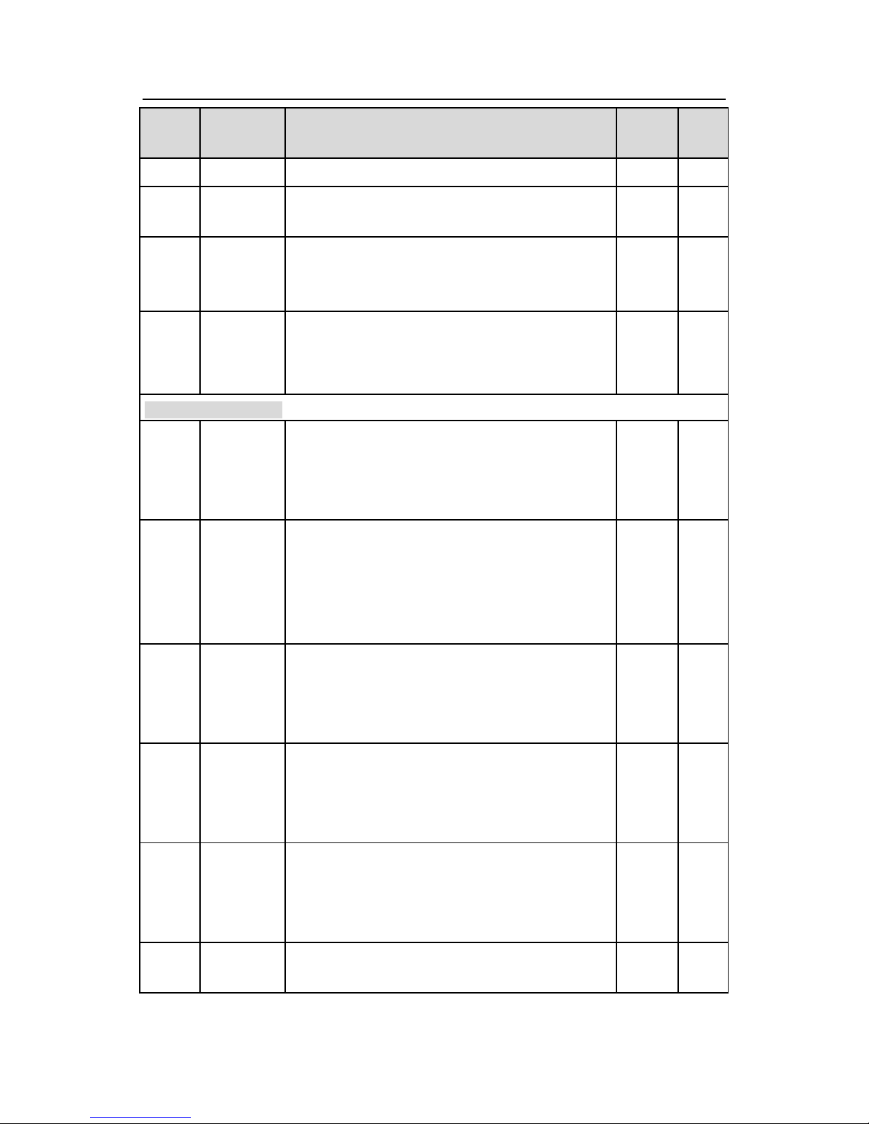
Goodrive300-16 special inverter for HVAC Appendix A
44
Function
code
Name
Detailed instruction of parameters
Default
value
Modify
power off
P01.23
Start delay
time
0.0~60.0s
0.0s
○
P01.24
Delay time
of stop
speed
0.0~100.0s
0.0s
○
P01.25
0Hz output
selection
0: Output without voltage
1: Output with voltage
2: Output at DC braking current at stopping
1
○
P02 Group Motor 1
P02.01
Rated
power of
asynchrono
us motor 1
0.1~3000.0kW
Depend
on
model
◎
P02.02
Rated
frequency
of
asynchrono
us motor 1
0.01Hz~P00.03 (Max. output frequency)
50.00Hz
◎
P02.03
Rated
speed of
asynchrono
us motor 1
1~36000rpm
Depend
on
model
◎
P02.04
Rated
voltage of
asynchrono
us motor 1
0~1200V
Depend
on
model
◎
P02.05
Rated
current of
asynchrono
us motor 1
0.8~6000.0A
Depend
on
model
◎
P02.06
Stator
resistor of
0.001~65.535Ω
Depend
on
○
Page 46

Goodrive300-16 special inverter for HVAC Appendix A
45
Function
code
Name
Detailed instruction of parameters
Default
value
Modify
asynchrono
us motor 1
model
P02.07
Rotor
resistor of
asynchrono
us motor 1
0.001~65.535Ω
Depend
on
model
○
P02.08
Leakage
inductance
of
asynchrono
us motor 1
0.1~6553.5mH
Depend
on
model
○
P02.09
Mutual
inductance
of
asynchrono
us motor 1
0.1~6553.5mH
Depend
on
model
○
P02.10
Non-load
current of
asynchrono
us motor 1
0.1~6553.5A
Depend
on
model
○
P02.11
Magnetic
saturation
coefficient
1 for the
iron core of
AM1
0.0~100.0%
80.0%
◎
P02.12
Magnetic
saturation
coefficient
2 for the
iron core of
AM1
0.0~100.0%
68.0%
◎
P02.13
Magnetic
0.0~100.0%
57.0%
◎
Page 47

Goodrive300-16 special inverter for HVAC Appendix A
46
Function
code
Name
Detailed instruction of parameters
Default
value
Modify
saturation
coefficient
3 for the
iron core of
AM1
P02.14
Magnetic
saturation
coefficient
4 for the
iron core of
AM1
0.0~100.0%
40.0%
◎
P02.26
Motor 1
overload
protection
0: No protection
1: Common motor (with low speed compensation).
2: Variable frequency motor (without low speed
compensation)
2
◎
P02.27
Motor 1
overload
protection
coefficient
20.0%~120.0%
100.0%
○
P02.28
Correction
coefficient
of motor 1
power
0.00~3.00
1.00
○
P03 Group Vector control
P03.00
Speed loop
proportiona
l gain1
0~200.0
20.0
○
P03.01
Speed loop
integral
time1
0.000~10.000s
0.200s
○
P03.02
Low
switching
0.00Hz~P03.05
5.00Hz
○
Page 48
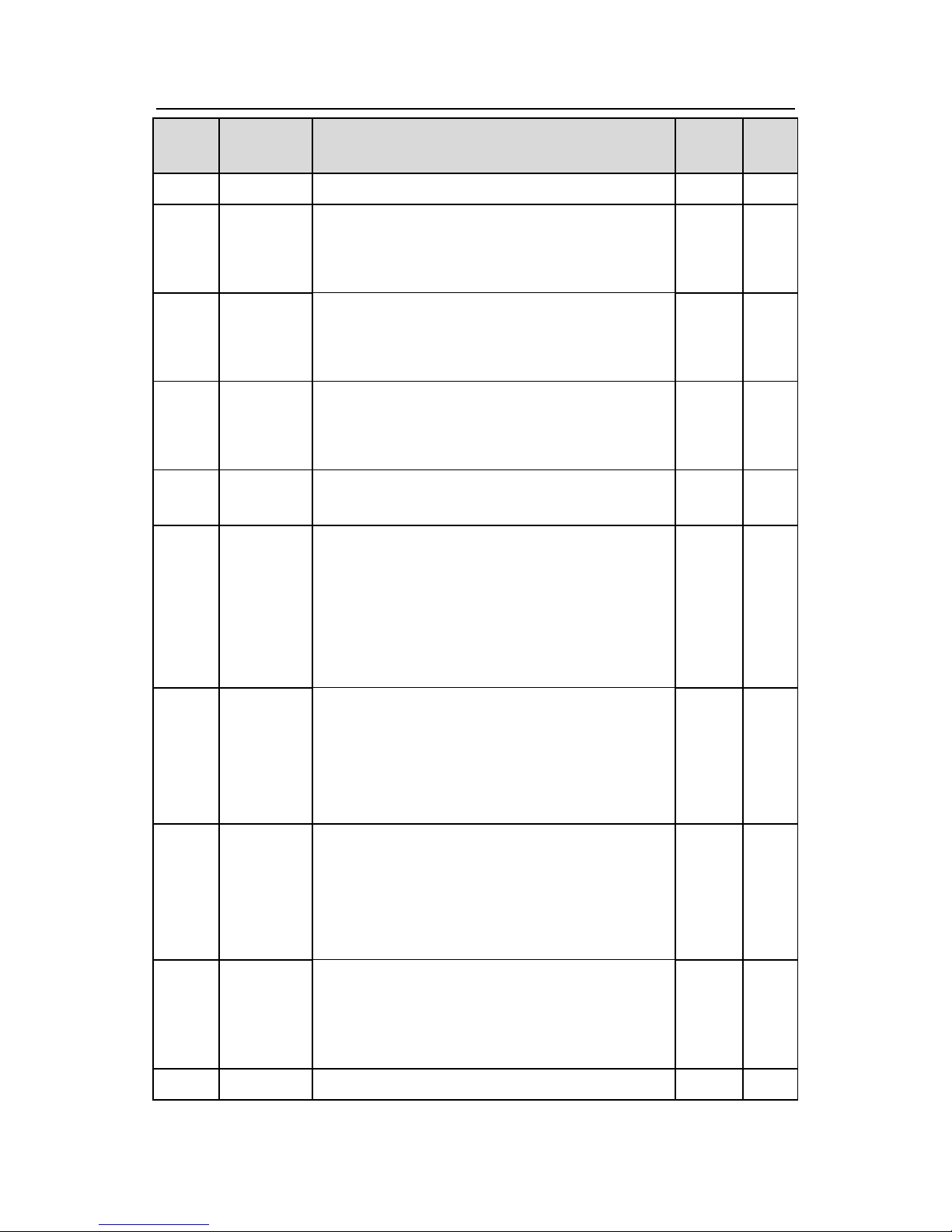
Goodrive300-16 special inverter for HVAC Appendix A
47
Function
code
Name
Detailed instruction of parameters
Default
value
Modify
frequency
P03.03
Speed loop
proportiona
l gain 2
0~200.0
20.0
○
P03.04
Speed loop
integral
time 2
0.000~10.000s
0.200s
○
P03.05
High
switching
frequency
P03.02~P00.03 (Max. output frequency)
10.00Hz
○
P03.06
Speed loop
output filter
0~8 (corresponds to 0~28/10ms)
0
○
P03.07
Compensat
ion
coefficient
of
electromoti
on slip
50%~200%
100%
○
P03.08
Compensat
ion
coefficient
of braking
slip
50%~200%
100%
○
P03.09
Current
loop
percentage
coefficient
P
0~65535
1000
○
P03.10
Current
loop
integral
coefficient I
0~65535
1000
○
P03.11
Torque
0: Torque control is invalid
0
○
Page 49
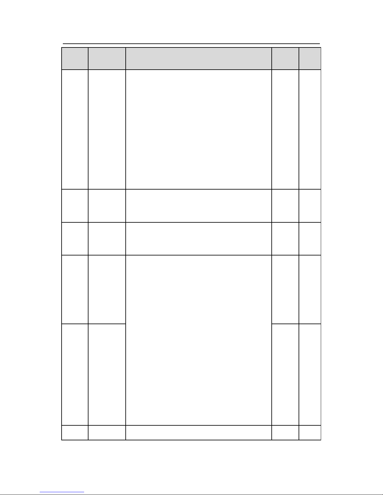
Goodrive300-16 special inverter for HVAC Appendix A
48
Function
code
Name
Detailed instruction of parameters
Default
value
Modify
setting
method
1: Keypad setting torque (P03.12)
2: Analog AI1 setting torque
3: Analog AI2 setting torque
4: Analog AI3 setting torque
5: Pulse frequency HDI setting torque
6: Multi-step torque setting
7: MODBUS communication setting torque
8: Profibus/CANopen/BACnet/Devicenet
communication setting torque
9: Ethernet communication setting torque
10: Reserved
P03.12
Keypad
setting
torque
-300.0%~300.0% (rated current of the motor)
50.0%
○
P03.13
Torque
reference
filter time
0.000~10.000s
0.010s
○
P03.14
Upper
frequency
of forward
rotation in
vector
control
0: Keypad
1: AI1
2: AI2
3: AI3
4: Pulse frequency HDI setting upper-limit
frequency
5: Multi-step setting upper-limit frequency
6: MODBUS communication setting upper-limit
frequency
7: Profibus/CANopen/BACnet/Devicenet
communication setting upper-limit frequency
8: Ethernet communication setting upper-limit
frequency
9: Reserved
0
○
P03.15
Upper
frequency
of reverse
rotation in
vector
control
0
○
P03.16
Keypad
0.00Hz~P00.03
50.00Hz
○
Page 50
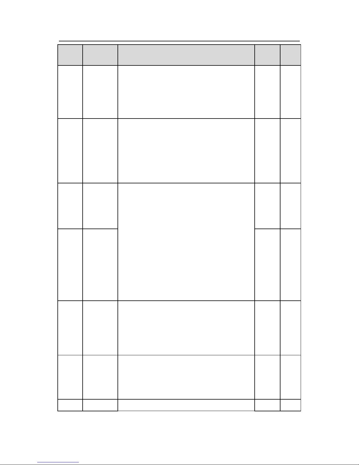
Goodrive300-16 special inverter for HVAC Appendix A
49
Function
code
Name
Detailed instruction of parameters
Default
value
Modify
setting for
upper
frequency
of forward
rotation
P03.17
Keypad
setting for
upper
frequency
of reverse
rotation
0.00Hz~P00.03
50.00Hz
○
P03.18
Upper
electromoti
on torque
source
0: Keypad setting upper-limit frequency
1: AI1
2: AI2
3: AI3
4: HDI
5: MODBUS communication
6: Profibus/CANopen/BACnet/Devicenet
communication
7: Ethernet communication
8: Reserved
0
○
P03.19
Upper
braking
torque
source
0
○
P03.20
Keypad
setting of
electromoti
on
torque
0.0~300.0% (motor rated current)
180.0%
○
P03.21
Keypad
setting of
braking
torque
0.0~300.0% (motor rated current)
180.0%
○
P03.22
Weakening
0.1~2.0
0.3
○
Page 51
Goodrive300-16 special inverter for HVAC Appendix A
50
Function
code
Name
Detailed instruction of parameters
Default
value
Modify
coefficient
in constant
power zone
P03.23
Lowest
weakening
point in
constant
power zone
10%~100%
20%
○
P03.24
Max.
voltage limit
0.0~120.0%
100.0%
◎
P03.25
Pre-excitin
g time
0.000~10.000s
0.300s
○
P03.26
Weak
magnetic
proportiona
l gain
0~8000
1000
○
P03.27
Vector
control
speed
0: Display the actual value
1: Display the setting value
1
○
P04 Group V/F control
P04.00
Motor 1 V/F
curve
setting
0: Straight line V/F curve
1: Multi-dots V/F curve
2: 1.3th power low torque V/F curve
3: 1.7th power low torque V/F curve
4: 2.0th power low torque V/F curve
5: Customized V/F(V/F separation)
0
◎
P04.01
Torque
boost of
motor 1
0.0%: (automatic) 0.1%~10.0%
0.0%
○
P04.02
Torque
boost close
0.0%~50.0% (relative to the rated frequency of
motor 1)
20.0%
○
Page 52

Goodrive300-16 special inverter for HVAC Appendix A
51
Function
code
Name
Detailed instruction of parameters
Default
value
Modify
of motor 1
P04.03
V/F
frequency 1
of motor 1
0.00Hz~P04.05
0.00Hz
○
P04.04
V/F
voltage 1 of
motor 1
0.0%~110.0% (the rated voltage of motor 1)
0.0%
○
P04.05
V/F
frequency 2
of motor 1
P04.03~P04.07
0.00Hz
○
P04.06
V/F
voltage 2 of
motor 1
0.0%~110.0% (the rated voltage of motor 1)
0.0%
○
P04.07
V/F
frequency 3
of motor 1
P04.05~P02.02 (the rated frequency of motor 1)
0.00Hz
○
P04.08
V/F
voltage 3 of
motor 1
0.0%~110.0% (the rated voltage of motor 1)
0.0%
○
P04.09
V/F slip
compensati
on gain of
motor 1
0.0~200.0%
100.0%
○
P04.10
Vibration
control
factor at
low
frequency
of motor 1
0~100
10
○
P04.11
Vibration
control
factor at
0~100
10
○
Page 53
Goodrive300-16 special inverter for HVAC Appendix A
52
Function
code
Name
Detailed instruction of parameters
Default
value
Modify
high
frequency
of motor 1
P04.12
Vibration
control
threshold of
motor 1
0.00Hz~P00.03 (Max.output frequency)
30.00Hz
○
P04.13
Motor 2 V/F
curve
setting
0: Straight line V/F curve
1: Multi-dots V/F curve
2: 1.3th power low torque V/F curve
3: 1.7th power low torque V/F curve
4: 2.0th power low torque V/F curve
5: Customized V/F(V/F separation)
0
◎
P04.14
Torque
boost of
motor 2
0.0%: (automatic) 0.1%~10.0%
0.0%
○
P04.15
Torque
boost close
of motor 2
0.0%~50.0% (relative to the rated frequency of
motor 2)
20.0%
○
P04.16
V/F
frequency 1
of motor 2
0.00Hz~P04.18
0.00Hz
○
P04.17
V/F
voltage 1 of
motor 2
0.0%~110.0% (the rated voltage of motor 2)
0.0%
○
P04.18
V/F
frequency 2
of motor 2
P04.16~P04.20
0.00Hz
○
P04.19
V/F
voltage 2 of
motor 2
0.0%~110.0% (the rated voltage of motor 2)
0.0%
○
P04.20
V/F
frequency 3
P04.18~P12.02 (the rated frequency of motor 2)/
P04.18~P12.16 (the rated frequency of motor 2)
0.00Hz
○
Page 54
Goodrive300-16 special inverter for HVAC Appendix A
53
Function
code
Name
Detailed instruction of parameters
Default
value
Modify
of motor 2
P04.21
V/F
voltage 3 of
motor 2
0.0%~110.0% (the rated voltage of motor 2)
0.0%
○
P04.22
V/F slip
compensati
on gain of
motor 2
0.0~200.0%
100.0%
○
P04.23
Vibration
control
factor at
low
frequency
of motor 2
0~100
10
○
P04.24
Vibration
control
factor at
high
frequency
of motor 2
0~100
10
○
P04.25
Vibration
control
threshold of
motor 2
0.00Hz~P00.03 (Max.output frequency)
30.00Hz
○
P04.26
Energy-sav
ing
operation
0:No operation
1:Automatic energy-saving operation
0
◎
P04.27
Voltage
setting
0: Keypad: the output voltage is determined by
P04.28.
1: AI1
2: AI2
3: AI3
4: HDI
5: Multi-step speed
0
○
Page 55
Goodrive300-16 special inverter for HVAC Appendix A
54
Function
code
Name
Detailed instruction of parameters
Default
value
Modify
6: PID1
7: MODBUS communication
8: Profibus/CANopen/BACnet/Devicenet
communication
9: Ethernet communication
10: Reserved
P04.28
Keypad
setting
voltage
0.0%~100.0%
100.0%
○
P04.29
Voltage
increasing
time
0.0~3600.0s
5.0s
○
P04.30
Voltage
decreasing
time
0.0~3600.0s
5.0s
○
P04.31
Maximum
output
voltage
P04.32~100.0% (the rated voltage of the motor)
100.0%
◎
P04.32
Minimum
output
voltage
0.0%~ P04.31 (the rated voltage of the motor)
0.0%
◎
P04.33
Weaking
coefficient
at constant
power
1.00~1.30
1.00
○
P05 Group Input terminals
P05.00
HDI input
selection
0: High pulse input
1: Digital input
0
●
P05.01
S1
terminals
function
selection
0: No function
1: Forward rotation operation
2: Reverse rotation operation
3: 3-wire control operation
1
◎
Page 56
Goodrive300-16 special inverter for HVAC Appendix A
55
Function
code
Name
Detailed instruction of parameters
Default
value
Modify
P05.02
S2
terminals
function
selection
4: Forward jogging
5: Reverse jogging
6: Coast to stop
7: Fault reset
8: Operation pause
9: External fault input
10: Increasing frequency setting (UP)
11: Decreasing frequency setting (DOWN)
12: Frequency setting clear
13: Shift between A setting and B setting
14: Shift between combination setting and A setting
15: Shift between combination setting and B setting
16: Multi-step speed terminal 1
17: Multi-step speed terminal 2
18: Multi-step speed terminal 3
19: Multi- step speed terminal 4
20: Multi- step speed pause
21: ACC/DEC time 1
22: ACC/DEC time 2
23: Simple PLC stop reset
24: Simple PLC pause
25: PID1 control pause
26: Traverse pause (stop at the current frequency)
27: Traverse reset (return to the center frequency)
28: Counter reset
29: Torque control disabling
30: ACC/DEC disabling
31: Counter trigging
32: Reserved
33: Cancel the frequency change setting
temporarily
34: DC brake
35: Shift the motor 1 into motor 2
36: Shift the command to the keypad
4
◎
P05.03
S3
terminals
function
selection
7
◎
P05.04
S4
terminals
function
selection
0
◎
P05.05
S5
terminals
function
selection
0
◎
P05.06
S6
terminals
function
selection
0
◎
P05.07
S7
terminals
function
selection
0
◎
P05.08
S8
terminals
function
selection
0
◎
P05.09
HDI
terminal
function
selection
0
◎
Page 57
Goodrive300-16 special inverter for HVAC Appendix A
56
Function
code
Name
Detailed instruction of parameters
Default
value
Modify
37: Shift the command to the terminals
38: Shift the command to the communication
39: Pre-magnetized command
40: Consumption power clear
41: Consumption power holding
42: Reserved
43: Reserved
44: PID1 integral pause
45: PID1 pole switching
46: Emergency deceleration to stop
47: PID2 start
48: PID2 stop
49: HVAC invalid (valid in stop state)
50: PID2 integral pause
51: PID2 control pause
52: PID2 pole switching
53: Fire signal trigging
54: Hibernation mode trigging
55: Waking up trigging
56: Motor A invalid
57: Motor B invalid
58: Motor C invalid
59: Motor D invalid
60: Motor E invalid
61: Motor F invalid
62: Motor G invalid
63: Motor H invalid
64: Manual circulation command
65: Manual soft start commissioning
66: Manual soft start of motor A
67: Manual soft start of motor B
68: Manual soft start of motor C
69: Manual soft start of motor D
70: Manual soft start of motor E
Page 58

Goodrive300-16 special inverter for HVAC Appendix A
57
Function
code
Name
Detailed instruction of parameters
Default
value
Modify
71: Manual soft start of motor F
72: Manual soft start of motor G
73: Manual soft start of motor H
74: Upper limit of water level of inlet sump
75: Lower limit of water level of inlet sump
76: Water shortage level of inlet sump
77~79: Reserved
P05.10
Polarity
selection of
the input
terminals
0x000~0x1FF
0x000
○
P05.11
ON-OFF
filter time
0.000~1.000s
0.010s
○
P05.12
Virtual
terminals
setting
0x000~0x1FF (0: Disabled, 1:Enabled )
BIT0: S1 virtual terminal
BIT1: S2 virtual terminal
BIT2: S3 virtual terminal
BIT3: S4 virtual terminal
BIT4: S5 virtual terminal
BIT5: S6 virtual terminal
BIT6: S7 virtual terminal
BIT7: S8 virtual terminal
BIT8: HDI virtual terminal
0x000
◎
P05.13
Terminals
control
running
mode
0: 2-wire control 1
1: 2-wire control 2
2: 3-wire control 1
3: 3-wire control 2
0
◎
P05.14
Switch-on
delay of S1
terminal
0.000~50.000s
0.000s
○
P05.15
Switch-off
delay of S1
terminal
0.000~50.000s
0.000s
○
Page 59

Goodrive300-16 special inverter for HVAC Appendix A
58
Function
code
Name
Detailed instruction of parameters
Default
value
Modify
P05.16
Switch-on
delay of S2
terminal
0.000~50.000s
0.000s
○
P05.17
Switch-off
delay of S2
terminal
0.000~50.000s
0.000s
○
P05.18
Switch-on
delay of S3
terminal
0.000~50.000s
0.000s
○
P05.19
Switch-off
delay of S3
terminal
0.000~50.000s
0.000s
○
P05.20
Switch-on
delay of S4
terminal
0.000~50.000s
0.000s
○
P05.21
Switch-off
delay of S4
terminal
0.000~50.000s
0.000s
○
P05.22
Switch-on
delay of S5
terminal
0.000~50.000s
0.000s
○
P05.23
Switch-off
delay of S5
terminal
0.000~50.000s
0.000s
○
P05.24
Switch-on
delay of S6
terminal
0.000~50.000s
0.000s
○
P05.25
Switch-off
delay of S6
terminal
0.000~50.000s
0.000s
○
P05.26
Switch-on
0.000~50.000s
0.000s
○
Page 60

Goodrive300-16 special inverter for HVAC Appendix A
59
Function
code
Name
Detailed instruction of parameters
Default
value
Modify
delay of S7
terminal
P05.27
Switch-off
delay of S7
terminal
0.000~50.000s
0.000s
○
P05.28
Switch-on
delay of S8
terminal
0.000~50.000s
0.000s
○
P05.29
Switch-off
delay of S8
terminal
0.000~50.000s
0.000s
○
P05.30
Switch-on
delay of
HDI
terminal
0.000~50.000s
0.000s
○
P05.31
Switch-off
delay of
HDI
terminal
0.000~50.000s
0.000s
○
P05.32
Lower limit
of AI1
0.00V~P05.34
0.00V
○
P05.33
Correspond
ing setting
of the lower
limit of AI1
-100.0%~100.0%
0.0%
○
P05.34
Upper limit
of AI1
P05.32~10.00V
10.00V
○
P05.35
Correspond
ing setting
of
the upper
-100.0%~100.0%
100.0%
○
Page 61
Goodrive300-16 special inverter for HVAC Appendix A
60
Function
code
Name
Detailed instruction of parameters
Default
value
Modify
limit of AI1
P05.36
AI1 input
filter time
0.000s~10.000s
0.100s
○
P05.37
Lower limit
of AI2
0.00V~P05.39
0.00V
○
P05.38
Correspond
ing setting
of the lower
limit of AI2
-100.0%~100.0%
0.0%
○
P05.39
Upper limit
of AI2
P05.37~10.00V
10.00V
○
P05.40
Correspond
ing setting
of
the upper
limit of AI2
-100.0%~100.0%
100.0%
○
P05.41
AI2 input
filter time
0.000s~10.000s
0.100s
○
P05.42
Lower limit
of
AI3
-10.00V~P05.44
-10.00V
○
P05.43
Correspond
ing setting
of the lower
limit of AI3
-100.0%~100.0%
-100.0%
○
P05.44
Middle
value of AI3
P05.42~P05.46
0.00V
○
P05.45
Correspond
ing middle
setting of
AI3
-100.0%~100.0%
0.0%
○
Page 62
Goodrive300-16 special inverter for HVAC Appendix A
61
Function
code
Name
Detailed instruction of parameters
Default
value
Modify
P05.46
Upper limit
of AI3
P05.44~10.00V
10.00V
○
P05.47
Correspond
ing setting
of
the upper
limit of AI3
-100.0%~100.0%
100.0%
○
P05.48
AI3 input
filter time
0.000s~10.000s
0.100s
○
P05.49
HDI
high-speed
pulse input
function
selection
0: Frequency setting input
1:Counter input
0
◎
P05.50
Lower limit
frequency
of HDI
0.000kHz~P05.52
0.000
kHz
○
P05.51
Correspond
ing setting
of HDI low
frequency
setting
-100.0%~100.0%
0.0%
○
P05.52
Upper limit
frequency
of HDI
P05.50~50.000kHz
50.000
kHz
○
P05.53
Correspond
ing setting
of upper
limit
frequency
of HDI
-100.0%~100.0%
100.0%
○
Page 63

Goodrive300-16 special inverter for HVAC Appendix A
62
Function
code
Name
Detailed instruction of parameters
Default
value
Modify
P05.54
HDI
frequency
input filter
time
0.000s~10.000s
0.010s
○
P06 Group Output terminals
P06.00
HDO output
0: Open collector pole high speed pulse output
1: Open collector pole output
0
◎
P06.01
Y output
0: Invalid
1: In operation
2: Forward rotation operation
3: Reverse rotation operation
4: Jogging operation
5: The inverter fault
6: Frequency degree test FDT1
7: Frequency degree test FDT2
8: Frequency arrival
9: Zero speed running
10: Upper limit frequency arrival
11: Lower limit frequency arrival
12: Ready for operation
13: Pre-magnetizing
14: Overload pre-alarm
15: Underload pre-alarm
16: Completion of simple PLC stage
17: Completion of simple PLC cycle
18: Setting count value arrival
19: Defined count value arrival
20: External fault valid
21: Reserved
22: Running time arrival
23: MODBUS communication virtual terminals
output
0
○
P06.02
HDO output
0
○
P06.03
Relay RO1
output
1
○
P06.04
Relay RO2
output
5
○
P06.05
Relay RO3
output
0
○
P06.06
Relay RO4
output
0
○
P06.07
Relay RO5
output
0
○
P06.08
Relay RO6
output
0
○
P06.09
Relay RO7
output
0
○
P06.10
Relay RO8
output
0
○
Page 64
Goodrive300-16 special inverter for HVAC Appendix A
63
Function
code
Name
Detailed instruction of parameters
Default
value
Modify
24: Profibus/CANopen/BACnet/Devicenet
communication virtual terminals output
25: Ethernet communication virtual terminals
output
26: Voltage establishment finished
27: Fire mode active state
28: Low PID1 feedback pre-alarm
29: High PID1 feedback pre-alarm
30: PID1 hibernation state
31: Realtime clock fault
32: PID2 start state
33: PID2 stop state
34: Connect motor A variable frequency
35: Connect motor A power frequency
36: Connect motor B variable frequency
37: Connect motor B power frequency
38: Connect motor C variable frequency
39: Connect motor C power frequency
40: Connect motor D variable frequency
41: Connect motor D power frequency
42: Connect motor E variable frequency
43: Connect motor E power frequency
44: Connect motor F variable frequency
45: Connect motor F power frequency
46: Connect motor G variable frequency
47: Connect motor G power frequency
48: Connect motor H variable frequency
49: Connect motor H power frequency
50: Standby pressure running indicating
51: Inlet sump water shortage indicating
52: Pre-alarm output
53~59: Reserved
Page 65

Goodrive300-16 special inverter for HVAC Appendix A
64
Function
code
Name
Detailed instruction of parameters
Default
value
Modify
P06.11
Polarity of
output
terminals
0~0x3FF
0~0x3FF
○
P06.12
HDO
switch-on
delay time
0.000~50.000s
0.000s
○
P06.13
HDO
switch-off
delay time
0.000~50.000s
0.000s
○
P06.14
Y1
switch-on
delay time
0.000~50.000s
0.000s
○
P06.15
Y1
switch-off
delay time
0.000~50.000s
0.000s
○
P06.16
RO1
switch-on
delay time
0.000~50.000s
0.000s
○
P06.17
RO1
switch-off
delay time
0.000~50.000s
0.000s
○
P06.18
RO2
switch-on
delay time
0.000~50.000s
0.000s
○
P06.19
RO2
switch-off
delay time
0.000~50.000s
0.000s
○
P06.20
RO3
switch-on
delay time
0.000~50.000s
0.000s
○
P06.21
RO3
0.000~50.000s
0.000s
○
Page 66

Goodrive300-16 special inverter for HVAC Appendix A
65
Function
code
Name
Detailed instruction of parameters
Default
value
Modify
switch-off
delay time
P06.22
RO4
switch-on
delay time
0.000~50.000s
0.000s
○
P06.23
RO4
switch-off
delay time
0.000~50.000s
0.000s
○
P06.24
RO5
switch-on
delay time
0.000~50.000s
0.000s
○
P06.25
RO5
switch-off
delay time
0.000~50.000s
0.000s
○
P06.26
RO6
switch-on
delay time
0.000~50.000s
0.000s
○
P06.27
RO6
switch-off
delay time
0.000~50.000s
0.000s
○
P06.28
RO7
switch-on
delay time
0.000~50.000s
0.000s
○
P06.29
RO7
switch-off
delay time
0.000~50.000s
0.000s
○
P06.30
RO8
switch-on
delay time
0.000~50.000s
0.000s
○
P06.31
RO8
switch-off
0.000~50.000s
0.000s
○
Page 67

Goodrive300-16 special inverter for HVAC Appendix A
66
Function
code
Name
Detailed instruction of parameters
Default
value
Modify
delay time
P06.32
AO1 output
0: Running frequency
1: Set frequency
2: Ramp reference frequency
3: Running rotation speed
4: Output current (relative to the rated current of the
inverter)
5: Output current (relative to the rated current of the
motor)
6: Output voltage
7: Output power
8: Set torque value
9: Output torque
10: Analog AI1 input value
11: Analog AI2 input value
12: Analog AI3 input value
13: High speed pulse HDI input value
14: MODBUS communication set value 1
15: MODBUS communication set value 2
16: Profibus/CANopen/BACnet/Devicenet
communication set value 1
17: Profibus/CANopen/BACnet/Devicenet
communication set value 2
18: Ethernet communication set value 1
19: Ethernet communication set value 2
20~21: Reserved
22: Torque current (relative to the rated current of
the motor)
23: Ramp reference frequency (with sign)
24: PID1 output
25: PID2 output
26: PID1 reference
0
○
P06.33
AO2 output
0
○
P06.34
HDO
high-speed
pulse
output
0
○
Page 68
Goodrive300-16 special inverter for HVAC Appendix A
67
Function
code
Name
Detailed instruction of parameters
Default
value
Modify
27: PID1 feedback
28: PID2 reference
29: PID2 feedback
30: Reserved
P06.35
Lower
output limit
of AO1
-100.0%~P06.37
0.0%
○
P06.36
Correspond
ing AO1
output of
lower limit
0.00V~10.00V
0.00V
○
P06.37
Upper
output limit
of AO1
P06.35~100.0%
100.0%
○
P06.38
The
correspondi
ng AO1
output of
upper limit
0.00V~10.00V
10.00V
○
P06.39
AO1 output
filter time
0.000s~10.000s
0.000s
○
P06.40
Lower
output limit
of AO2
-100.0%~P06.42
0.0%
○
P06.41
Correspond
ing AO2
output of
lower limit
0.00V~10.00V
0.00V
○
P06.42
Upper
output limit
of AO2
P06.40~100.0%
100.0%
○
Page 69

Goodrive300-16 special inverter for HVAC Appendix A
68
Function
code
Name
Detailed instruction of parameters
Default
value
Modify
P06.43
The
correspondi
ng AO2
output of
upper limit
0.00V~10.00V
10.00V
○
P06.44
AO2 output
filter time
0.000s~10.000s
0.000s
○
P06.45
Lower
output limit
of HDO
-100.0%~P06.47
0.00%
○
P06.46
Correspond
ing HDO
output of
lower limit
0.000~50.000kHz
0.000
kHz
○
P06.47
Upper
output limit
of HDO
P06.45~100.0%
100.0%
○
P06.48
Correspond
ing HDO
output of
upper limit
0.00~50.00kHz
50.00
kHz
○
P06.49
HDO output
filter time
0.000s~10.000s
0.000s
○
P07 Group Human-Machine Interface
P07.00
User’s
password
0~65535
0
○
P07.01
Parameter
copy
0: No operation
1: Upload the local function parameter to the
keypad
2: Download the keypad function parameter to local
address (including the motor parameters)
0
◎
Page 70
Goodrive300-16 special inverter for HVAC Appendix A
69
Function
code
Name
Detailed instruction of parameters
Default
value
Modify
3: Download the keypad function parameter to local
address (excluding the motor parameter of P02
and P12 group)
4: Download the keypad function parameters to
local address (only for the motor parameter of P02
and P12 group)
P07.02
QUICK/JO
G function
selection
0: No function
1: Jogging
2: Shift the display state by the shifting key
3: Shift between forward rotations and reverse
rotations
4: Clear UP/DOWN settings
5: Coast to stop
6: Shift the given manner of running commands
7: Quick commission mode (committee according
to the non-factory parameter)
1
◎
P07.03
Shifting
sequence
selection of
QUICK/JO
G
commands
0: Keypad control→terminals control
→communication control
1: Keypad control←→terminals control
2: Keypad control←→communication control
3: Terminals control←→communication control
0
○
P07.04
STOP/RST
stop
function
0: Only valid for the keypad control
1: Both valid for keypad and terminals control
2: Both valid for keypad and communication control
3: Valid for all control modes
0
○
P07.05
Parameters
state 1
0x0000~0xFFFF
BIT0: running frequency (Hz on)
BIT1: set frequency(Hz flickering)
BIT2: bus voltage (Hz on)
BIT3: output voltage(V on)
BIT4: output current(A on)
0x0c1F
○
Page 71

Goodrive300-16 special inverter for HVAC Appendix A
70
Function
code
Name
Detailed instruction of parameters
Default
value
Modify
BIT5: running rotation speed (rpm on)
BIT6: output power (% on)
BIT7: output torque (% on)
BIT8: PID1 reference (% flickering)
BIT9: PID1 feedback value (% on)
BIT10: input terminals state
BIT11: output terminals state
BIT12: torque set value (% on)
BIT13: pulse counter value
BIT14: reserved
BIT15: PLC and the current stage in multi-step
speed
P07.06
Parameters
state 2
0x0000~0xFFFF
BIT0: AI1 (V on)
BIT1: AI2 (V on)
BIT2: AI3 (V on)
BIT3: HDI frequency
BIT4: motor overload percentage (% on)
BIT5: the inverter overload percentage (% on)
BIT6: ramp frequency given value(Hz on)
BIT7: linear speed
BIT8: AC inlet current (A on)
BIT9: upper limit frequency (Hz on)
BIT10~15: reserved
0x0000
○
P07.07
Parameters
for stopping
state
0x0000~0xFFFF
BIT0: set frequency (Hz on, frequency flickering
slowly)
BIT1: bus voltage (V on)
BIT2: input terminals state
BIT3: output terminals state
BIT4: PID1 reference (% flickering)
BIT5: PID1 feedback value (% on)
0x100F
○
Page 72
Goodrive300-16 special inverter for HVAC Appendix A
71
Function
code
Name
Detailed instruction of parameters
Default
value
Modify
BIT6: torque reference (% on)
BIT7: AI1 (V on)
BIT8: AI2 (V on)
BIT9: AI3 (V on)
BIT10: HDI frequency
BIT11: PLC and the current stage in multi-step
speed
BIT12: pulse counters
BIT13: reserved
BIT14: upper limit frequency (Hz on)
BIT15: reserved
P07.08
Frequency
coefficient
0.01~10.00
1.00
○
P07.09
Rotation
speed
coefficient
0.1~999.9%
100.0%
○
P07.10
Linear
speed
coefficient
0.1~999.9%
1.0%
○
P07.11
Rectifier
bridge
module
temperature
-20.0~120.0℃
●
P07.12
Converter
module
temperature
-20.0~120.0℃
●
P07.13
Software
version
1.00~655.35
●
P07.14
Local
accumulative
running time
0~65535h
●
Page 73
Goodrive300-16 special inverter for HVAC Appendix A
72
Function
code
Name
Detailed instruction of parameters
Default
value
Modify
P07.15
High bit of
power
consumption
0~65535°(*1000)
P07.16
Low bit of
power
consumption
0.0~999.9kWh
P07.18
The rated
power of
the inverter
0.4~3000.0kW
● P07.19
The rated
voltage of
the inverter
50~1200V
●
P07.20
The rated
current of
the inverter
0.1~6000.0A
●
P07.21
Factory bar
code 1
0x0000~0xFFFF
● P07.22
Factory bar
code 2
0x0000~0xFFFF
● P07.23
Factory bar
code 3
0x0000~0xFFFF
● P07.24
Factory bar
code 4
0x0000~0xFFFF
●
P07.25
Factory bar
code 5
0x0000~0xFFFF
●
P07.26
Factory bar
code 6
0x0000~0xFFFF
●
Page 74
Goodrive300-16 special inverter for HVAC Appendix A
73
Function
code
Name
Detailed instruction of parameters
Default
value
Modify
P07.27
Current
fault type
0: No fault
1: IGBT U phase protection(OUt1)
2: IGBT V phase protection(OUt2)
3: IGBT W phase protection(OUt3)
4: OC1
5: OC2
6: OC3
7: OV1
8: OV2
9: OV3
10: UV
11: Motor overload (OL1)
12: The inverter overload (OL2)
13: Input side phase loss (SPI)
14: Output side phase loss (SPO)
15: Overheat of the rectifier module (OH1)
16: Overheat fault of the inverter module (OH2)
17: External fault (EF)
18: 485 communication fault (CE)
19: Current detection fault (ItE)
20: Motor antotune fault (tE)
21: EEPROM operation fault (EEP)
22: PID1 response offline fault (PIDE)
23: Braking unit fault (bCE)
24: Running time arrival (END)
25: Electrical overload (OL3)
26: Panel communication fault (PCE)
27: Parameter uploading fault (UPE)
28: Parameter downloading fault (DNE)
29: Profibus/BACnet communication fault (E-DP )
30: Ethernet communication fault (E-NET)
31: CANopen/Devicenet communication fault
●
P07.28
Previous
fault type
●
P07.29
Previous 2
fault type
●
P07.30
Previous 3
fault type
●
P07.31
Previous 4
fault type
●
P07.32
Previous 5
fault type
●
Page 75
Goodrive300-16 special inverter for HVAC Appendix A
74
Function
code
Name
Detailed instruction of parameters
Default
value
Modify
(E-CAN)
32: Grounding short circuit fault 1 (ETH1)
33: Grounding short circuit fault 2 (ETH2)
34: Speed deviation fault (dEu)
35: Maladjustment (STo)
36: Undervoltage fault (LL)
37: Clock chip fault (TI-E)
P07.33
Running
frequency
at current
fault
0.00Hz
●
P07.34
Ramp
reference
frequency
at current
fault
0.00Hz
●
P07.35
Output
voltage at
the current
fault
0V
●
P07.36
Output
current at
current fault
0.0A
●
P07.37
Bus voltage
at current
fault
0.0V
●
P07.38
The Max.
temperature
at current
fault
0.0℃
●
P07.39
Input
0
●
Page 76

Goodrive300-16 special inverter for HVAC Appendix A
75
Function
code
Name
Detailed instruction of parameters
Default
value
Modify
terminals
state at
current fault
P07.40
Output
terminals
state at
current fault
0
●
P07.41
Running
frequency
at previous
fault
0.00Hz
●
P07.42
Ramp
reference
frequency
at previous
fault
0.00Hz
●
P07.43
Output
voltage at
previous
fault
0V
●
P07.44
The output
current at
previous
fault
0.0A
●
P07.45
Bus voltage
at previous
fault
0.0V
●
P07.46
The Max.
temperature
at previous
fault
0.0℃
●
Page 77
Goodrive300-16 special inverter for HVAC Appendix A
76
Function
code
Name
Detailed instruction of parameters
Default
value
Modify
P07.47
Input
terminals
state at
previous
fault
0
●
P07.48
Output
terminals
state at
previous
fault
0
●
P07.49
Running
frequency
at previous
2 fault
0.00Hz
●
P07.50
Output
voltage at
previous 2
faults
0.00Hz
●
P07.51
Output
current at
previous 2
faults
0V
●
P07.52
Output
current at
previous 2
fault
0.0A
●
P07.53
Bus voltage
at previous
2 fault
0.0V
●
P07.54
The Max.
temperature
0.0℃
●
Page 78
Goodrive300-16 special inverter for HVAC Appendix A
77
Function
code
Name
Detailed instruction of parameters
Default
value
Modify
at previous 2
fault
P07.55
Input
terminals
state at
previous 2
fault
0
●
P07.56
Output
terminals
state at
previous 2
fault
0
●
P08 Group Enhanced function
P08.00
ACC time 2
0.0~3600.0s
Depend
on
model
○
P08.01
DEC time 2
0.0~3600.0s
Depend
on
model
○
P08.02
ACC time 3
0.0~3600.0s
Depend
on
model
○
P08.03
DEC time 3
0.0~3600.0s
Depend
on
model
○
P08.04
ACC time 4
0.0~3600.0s
Depend
on
model
○
P08.05
DEC time 4
0.0~3600.0s
Depend
on
model
○
Page 79

Goodrive300-16 special inverter for HVAC Appendix A
78
Function
code
Name
Detailed instruction of parameters
Default
value
Modify
P08.06
Jogging
frequency
0.00Hz~P00.03 (Max.output frequency)
5.00Hz
○
P08.07
Jogging
ACC time
0.0~3600.0s
Depend
on
model
○
P08.08
Jogging
DEC time
0.0~3600.0s
Depend
on
model
○
P08.09
Jumping
frequency 1
0.00Hz~P00.03 (Max.output frequency)
0.00Hz
○
P08.10
Jumping
frequency
range 1
0.00Hz~P00.03 (Max.output frequency)
0.00Hz
○
P08.11
Jumping
frequency 2
0.00Hz~P00.03 (Max.output frequency)
0.00Hz
○
P08.12
Jumping
frequency
range 2
0.00Hz~P00.03 (Max.output frequency)
0.00Hz
○
P08.13
Jumping
frequency 3
0.00Hz~P00.03 (Max.output frequency)
0.00Hz
○
P08.14
Jumping
frequency
range 3
0.00Hz~P00.03 (Max.output frequency)
0.00Hz
○
P08.15
Traverse
range
0.0~100.0% (relative to the set frequency)
0.0%
○
P08.16
Sudden
jumping
frequency
range
0.0~50.0% (relative to the traverse range)
0.0%
○
P08.17
Traverse
boost time
0.1~3600.0s
5.0s
○
Page 80

Goodrive300-16 special inverter for HVAC Appendix A
79
Function
code
Name
Detailed instruction of parameters
Default
value
Modify
P08.18
Traverse
declining
time
0.1~3600.0s
5.0s
○
P08.25
Setting
counting
value
P08.26~65535
0
○
P08.26
Reference
counting
value
0~P08.25
0
○
P08.27
Set running
time
0~65535min
0min
○
P08.28
Fault reset
times
0~10
0
○
P08.29
Interval
time of
automatic
fault reset
0.1~3600.0s
1.0s
○
P08.30
Frequency
decreasing
ratio of the
dropping
control
0.00~50.00Hz
0.00Hz
○
P08.31
Motor
shifting
0x00~0x14
LED ones: shifting channel
0: terminal shifting
1: MODBUS communication shifting
2: Profibus/CANopen communication shifting
3: Ethernet communication shifting
4: Reserved
LED tens: shifting enabling in operation
0: Disabled
0x00
◎
Page 81
Goodrive300-16 special inverter for HVAC Appendix A
80
Function
code
Name
Detailed instruction of parameters
Default
value
Modify
1: Enabled
P08.32
FDT1
electrical
level
detection
value
0.00Hz~P00.03 (Max.output frequency)
50.00Hz
○
P08.33
FDT1
retention
detection
value
-100.0~100.0% (FDT1 electrical level)
5.0%
○
P08.34
FDT2
electrical
level
detection
value
0.00Hz~P00.03 (Max.output frequency)
50.00Hz
○
P08.35
FDT2
retention
detection
value
-100.0~100.0% (FDT2 electrical level)
5.0%
○
P08.36
Frequency
arrival
detection
value
0.00Hz~P00.03 (Max.output frequency)
0.00Hz
○
P08.37
Energy
braking
enable
0:Disable
1:Enable
0
○
P08.38
Threshold
voltage
200.0~2000.0V
700.0V
○
P08.39
Cooling fan
0: Normal mode
0
○
Page 82
Goodrive300-16 special inverter for HVAC Appendix A
81
Function
code
Name
Detailed instruction of parameters
Default
value
Modify
running
mode
1:The fan keeps running after power on
P08.40
PWM
selection
0x00~0x21
LED ones: PWM mode selection
0: PWM mode 1, three-phase modulation and
two-modulation
1: PWM mode 2, three-phase modulation
LED tens: low-speed carrier frequency limit mode
0: Low-speed carrier frequency limit mode 1
1: Low-speed carrier frequency limit mode 2
2: No limit
01
◎
P08.41
Over
commission
selection
0x00~0x11
LED ones
0: Invalid
1: Valid
LED tens
0: Light overcommission
1: Heavy overcommission
01
◎
P08.42
Keypad
data control
0x000~0x1223
LED ones: frequency enable selection
0: Both ∧/∨ keys and digital potentiometer
adjustments are valid
1: Only ∧/∨ keys adjustment is valid
2: Only digital potentiometer adjustments is valid
3: Neither ∧/∨ keys nor digital potentiometer
adjustments are valid
LED tens: frequency control selection
0: Only valid when P00.06=0 or P00.07=0
1: Valid for all frequency setting manner
2: Invalid for multi-step speed when multi-step
speed has the priority
LED hundreds: action selection during stopping
0x0000
○
Page 83
Goodrive300-16 special inverter for HVAC Appendix A
82
Function
code
Name
Detailed instruction of parameters
Default
value
Modify
0: Setting is valid
1: Valid during running, cleared after stopping
2: Valid during running, cleared after receiving the
stop command
LED thousands: ∧/∨ keys and digital
potentiometer integral function
0: The integral function is valid
1: The integral function is invalid
P08.43
Integral ratio
of the keypad
potentiometer
0.01~10.00s
0.10s
○
P08.44
UP/DOWN
terminals
control
0x000~0x221
LED ones: frequency control selection
0: UP/DOWN terminals setting valid
1: UP/DOWN terminals setting valid
LED tens: frequency control selection
0: Only valid when P00.06=0 or P00.07=0
1: All frequency means are valid
2: When the multi-step are priority, it is invalid to
the multi-step
LED hundreds: action selection when stop
0: Setting valid
1: Valid in the running, clear after stop
2: Valid in the running, clear after receiving the stop
commands
0x000
○
P08.45
UP
terminals
frequency
changing
ratio
0.01~50.00Hz/s
0.50
Hz/s
○
P08.46
DOWN
terminals
0.01~50.00 Hz/s
0.50
Hz/s
○
Page 84

Goodrive300-16 special inverter for HVAC Appendix A
83
Function
code
Name
Detailed instruction of parameters
Default
value
Modify
frequency
changing
ratio
P08.47
Frequency
setting at
power loss
0x000~0x111
LED ones: Action selection when power off.
0: Save when power off
1: Clear when power off
LED tens: Action selection when MODBUS set
frequency off
0: Save when power off
1: Clear when power off
LED hundreds:The action selection when other
frequency set frequency off
0: Save when power off
1: Clear when power off
0x000
○
P08.48
High bit of
initial power
consumption
0~59999kWh(k)
0°
○
P08.49
Low bit of
initial power
consumption
0.0~999.9kWh
0.0°
○
P08.50
Magnetic
flux braking
0: Invalid.
100~150: The bigger the coefficient, the stronger
the braking is.
0
○
P08.51
Input power
factor of the
inverter
0.00~1.00
0.56
○
P09 Group PID1 control
P09.00
Unit
selection
0: MPa
1: KPa
2: Pa
3: A
0
◎
Page 85

Goodrive300-16 special inverter for HVAC Appendix A
84
Function
code
Name
Detailed instruction of parameters
Default
value
Modify
4: V
5: %
6: m/s
7: m/Min
8: m/h
9: m3/s
10: m3/Min
11: m3/h
12: Kg/s
13: Kg/Min
14: Kg/h
15~21: Reserved
P09.01
Displayed
decimal
places
0~4
3
◎
P09.02
Max. PID1
reference
0.001~65.535
3 decimal places, the decimal place changes along
with P09.01
1.000
○
P09.03
Upper limit
of PID1
reference
P09.04~P09.02
1.000
○
P09.04
Lower limit
of PID1
reference
0.001~P09.03
0.100
○
P09.05
PID1
reference
source 1
0: P09.07
1: P09.08
2: AI1
3: AI2
4: AI3
5: HDI
6: Multi-step speed
7: MODBUS
8: Profibus-DP/CANopen/BACnet
9: Ethernet
0
○
Page 86
Goodrive300-16 special inverter for HVAC Appendix A
85
Function
code
Name
Detailed instruction of parameters
Default
value
Modify
10: Reserved
P09.06
PID1
reference
source 2
0: P09.07
1: P09.08
2: AI1
3: AI2
4: AI3
5: HDI
6: Multi-step speed
7: MODBUS
8: Profibus-DP/CANopen/BACnet
9: Ethernet
10: Reserved
0
○
P09.07
PID1
keypad
reference 1
P09.04~P09.03
0.100
○
P09.08
PID1
keypad
reference 2
P09.04~P09.03
0.100
○
P09.09
PID1
reference
ACC/DEC
time
0.0~1000.0s
0.0s
○
P09.10
PID1
feedback
source 1
0: AI1
1: AI2
2: AI3
3: HDI
4: MODBUS
5: Profibus-DP/CANopen/BACnet
6: Ethernet
7: Reserved
0
○
P09.11
PID1
feedback
source 2
0: AI1
1: AI2
2: AI3
3: HDI
0
○
Page 87

Goodrive300-16 special inverter for HVAC Appendix A
86
Function
code
Name
Detailed instruction of parameters
Default
value
Modify
4: MODBUS
5: Profibus-DP/CANopen/BACnet
6: Ethernet
7: Reserved
P09.12
PID1
feedback
filter time
0.000~60.000s
0.000s
○
P09.13
Feedback
source 1
conversion
gain
0.00~600.00
1.00
○
P09.14
Feedback
source 2
conversion
gain
0.00~600.00
1.00
○
P09.15
Feedback
function
0: No combination feedback source 1
1: Sum feedback source 1+feedback source 2
2: Difference feedback source 1-feedback source 2
3: Average average feedback source 1 and
feedback source 2
4: Minimize minimize feedback source 1 and
feedback source 2
5: Maximize maximize feedback source 1 and
feedback source 2
6: Multi-reference minimum positive deviation and
maximum negative deviation
Calculate the difference of reference source 1 and
feedback source 1, reference source 2 and
feedback source 2 and consider the case when the
feedback is larger than the reference in priority.
If the feedback is larger than the corresponding
reference, take the maximum negative deviation as
PID reference and feedback. If the feedback is
smaller than the corresponding reference, take the
0
○
Page 88
Goodrive300-16 special inverter for HVAC Appendix A
87
Function
code
Name
Detailed instruction of parameters
Default
value
Modify
minimum positive deviation as PID reference and
feedback.
7: Multi-reference maximum positive deviation and
minimum negative deviation
Calculate the difference of reference source 1 and
feedback source 1, reference source 2 and
feedback source 2 and consider the case when the
feedback is smaller than the reference in priority.
If the feedback is smaller than the corresponding
reference, take the maximum positive deviation as
PID reference and feedback. If the feedback is
larger than the corresponding reference, take the
minimum negative deviation as PID reference and
feedback.
P09.16
PID output
feature
0~1
0
○
P09.17
Proportiona
l gain
0.00~100.00
1.00
○
P09.18
Integral
time
0.00~30.00s
0.10s
○
P09.19
Differential
time
0.00~10.00s
0.00s
○
P09.20
Sampling
cycle
0.001~10.000s
0.100s
○
P09.21
PID1
control
dead area
0.0~100.0%
1.0%
○
P09.22
Dead area
delay
0.0~300.0s
PID deviation maintains P09.22 in the range of
P09.21, no adjustment when PID enters dead area
1.0s
○
P09.23
PID1 output
upper limit
P09.24~100.0%
100.0%
○
P09.24
PID1 output
-100.0~P09.23
0.0%
○
Page 89
Goodrive300-16 special inverter for HVAC Appendix A
88
Function
code
Name
Detailed instruction of parameters
Default
value
Modify
lower limit
P09.25
PID1
adjustment
0x000~0x111
LED ones: Integral anti-saturation
0: Keep on integral adjustment when the frequency
achieves the upper and low limit; the integration
shows the change between the reference and the
feedback unless it reaches the internal integral
limit. When the trend between the reference and
the feedback changes, it needs more time to offset
the impact of continuous working and the
integration will change with the trend.
1: Stop integral adjustment when the frequency
achieves the upper and low limit. If the integration
keeps stable, and the trend between the reference
and the feedback changes, the integration will
change with the trend quickly.
LED tens: Motor running direction
0: The same with the setting direction; if the output
of PID adjustment is different from the current
running direction, the internal will output 0 forcedly.
1:Opposite to the setting direction; if the output of
PID adjustment is different from the current running
direction, execute close loop adjustment output
which is opposite to the setting direction.
LED hundreds: Integral separation
0: Invalid
1: Valid, stop integral adjustment when PID input
deviation is larger than P09.27
0x001
○
P09.26
PID1
deviation
input limit
0.0~100.0%
100.0%
○
P09.27
Integral
0.0~200.0%
200.0%
○
Page 90

Goodrive300-16 special inverter for HVAC Appendix A
89
Function
code
Name
Detailed instruction of parameters
Default
value
Modify
separation
threshold
P09.28
Differential
filter times
0~30
2
○
P09.29
PID1 output
gain
0.30~3.00
1.00
○
P09.30
PID1 output
filter time
0.000~60.000s
0.000s
○
P09.31
Feedback
upper limit
detection
value
-100.0~100.0%
Not detect over feedback upper limit When setting
to 100.0%
100.0%
○
P09.32
Feedback
lower limit
detection
value
-100.0~100.0%
Not detect over feedback lower limit When setting
to 0.0%
0.0%
○
P09.33
Feedback
over limit
detection
time
0.0~3600.0s
1.0s
○
P09.34
PID1
control
mode
0: Feedback differential processing
1: Deviation differential processing
0
◎
P10 Group Simple PLC and multi-step speed control
P10.00
Simple PLC
0: Stop after running once
1: Run at the final value after running once
2: Cycle running
0
○
P10.01
Simple
PLC
memory
0: Power loss without memory
1: Power loss memory
0
○
P10.02
Multi-step
speed 0
-100.0~100.0%
0.0%
○
P10.03
Running
0.0~6553.5s(m)
0.0s
○
Page 91
Goodrive300-16 special inverter for HVAC Appendix A
90
Function
code
Name
Detailed instruction of parameters
Default
value
Modify
time of step
0
P10.04
Multi-step
speed 1
-100.0~100.0%
0.0%
○
P10.05
Running
time of step
1
0.0~6553.5s(m)
0.0s
○
P10.06
Multi-step
speed 2
-100.0~100.0%
0.0%
○
P10.07
Running
time of step
2
0.0~6553.5s(m)
0.0s
○
P10.08
Multi-step
speed 3
-100.0~100.0%
0.0%
○
P10.09
Running
time of step
3
0.0~6553.5s(m)
0.0s
○
P10.10
Multi-step
speed 4
-100.0~100.0%
0.0%
○
P10.11
Running
time of step
4
0.0~6553.5s(m)
0.0s
○
P10.12
Multi-step
speed 5
-100.0~100.0%
0.0%
○
P10.13
Running
time of step
5
0.0~6553.5s(m)
0.0s
○
P10.14
Multi-step
speed 6
-100.0~100.0%
0.0%
○
P10.15
Running
time of step
0.0~6553.5s(m)
0.0s
○
Page 92
Goodrive300-16 special inverter for HVAC Appendix A
91
Function
code
Name
Detailed instruction of parameters
Default
value
Modify
6
P10.16
Multi-step
speed 7
-100.0~100.0%
0.0%
○
P10.17
Running
time of step
7
0.0~6553.5s(m)
0.0s
○
P10.18
Multi-step
speed 8
-100.0~100.0%
0.0%
○
P10.19
Running
time of step
8
0.0~6553.5s(m)
0.0s
○
P10.20
Multi-step
speed 9
-100.0~100.0%
0.0%
○
P10.21
Running
time of step
9
0.0~6553.5s(m)
0.0s
○
P10.22
Multi-step
speed 10
-100.0~100.0%
0.0%
○
P10.23
Running
time of step
10
0.0~6553.5s(m)
0.0s
○
P10.24
Multi-step
speed 11
-100.0~100.0%
0.0%
○
P10.25
Running
time of step
11
0.0~6553.5s(m)
0.0s
○
P10.26
Multi-step
speed 12
-100.0~100.0%
0.0%
○
P10.27
Running
time of step
12
0.0~6553.5s(m)
0.0s
○
Page 93
Goodrive300-16 special inverter for HVAC Appendix A
92
Function
code
Name
Detailed instruction of parameters
Default
value
Modify
P10.28
Multi-step
speed 13
-100.0~100.0%
0.0%
○
P10.29
Running
time of step
13
0.0~6553.5s(m)
0.0s
○
P10.30
Multi-step
speed 14
-100.0~100.0%
0.0%
○
P10.31
Running
time of step
14
0.0~6553.5s(m)
0.0s
○
P10.32
Multi-step
speed 15
-100.0~100.0%
0.0%
○
P10.33
Running
time of step
15
0.0~6553.5s(m)
0.0s
○
P10.34
Simple PLC
0~7 step
ACC/DEC
time
0x0000~0xFFFF
0x0000
○
P10.35
Simple PLC
8~15 step
ACC/DEC
time
0x0000~0xFFFF
0x0000
○
P10.36
PLC restart
0: Restart from the first step
1: Continue to run from the stop frequency
0
◎
P10.37
Multi-step
time unit
0: Seconds
1: Minutes
0
◎
P11 Group Protective parameters
P11.00
Phase loss
protection
LED ones:
0: Input phase loss protection disable
1: Input phase loss protection enable
LED tens:
Depend
on
model
○
Page 94

Goodrive300-16 special inverter for HVAC Appendix A
93
Function
code
Name
Detailed instruction of parameters
Default
value
Modify
0: Output phase loss protection disable
1: Output phase loss protection enable
LED hundreds:
0: Hardware input phase loss protection disable
1: Hardware input phase loss protection enable
P11.01
Frequency-
decreasing
at sudden
power loss
0: Disable
1: Enable
0
○
P11.02
Frequency
decreasing
ratio at
sudden
power loss
0.00Hz/s~P00.03 (Max.output frequency)
10.00
Hz/s
○
P11.03
Overvoltage
stall
protection
0: Disable
1: Enable
1
○
P11.04
Voltage
protection
of
overvoltage
stall
120~150% (standard bus voltage)(380V)
136%
○
120~150% (standard bus voltage)(220V)
120%
P11.05
Current
limit action
selection
0x00~0x11
LED ones: current limit:
0: Invalid
1: Valid
LED tens: overload alarm of hardware current limit
0: Valid
1: Invalid
01
◎
Page 95
Goodrive300-16 special inverter for HVAC Appendix A
94
Function
code
Name
Detailed instruction of parameters
Default
value
Modify
P11.06
Automatic
current limit
50.0~200.0%
160.0%
◎
P11.07
Frequency-
decreasing
ratio during
current limit
0.00~50.00Hz/s
3.00
Hz/s
◎
P11.08
Overload
pre-alarm
of motor/
inverter
0x000~0x131
LED ones:
0: Overload pre-alarm of the motor, relative to the
rated current of the motor
1: Overload pre-alarm of the inverter, relative to the
rated current of the inverter
LED tens:
0: The inverter continues to work after underload
pre-alarm
1: The inverter continues to work after underload
pre-alarm and the inverter stops to run after
overload fault
2: The inverter continues to work after overload
pre-alarm and the inverter stops to run after
underload fault
3. The inverter stops running after overload and
unerload fault
LED hundreds :
0: Detection all the time
1: Detection in constant running
0x000
○
Page 96
Goodrive300-16 special inverter for HVAC Appendix A
95
Function
code
Name
Detailed instruction of parameters
Default
value
Modify
P11.09
Overload
pre-alarm
detection
P11.11~200%
150%
○
P11.10
Overload
pre-alarm
detection
time
0.01~360.00s
1.00s
○
P11.11
Underload
pre-alarm
detection
0%~ P11.09
25%
○
P11.12
Underload
pre-alarm
detection
time
0.01~360.0s
0.05s
○
P11.13
Output
terminal
action
during fault
0x00~0x11
LED ones:
0: Action under fault undervoltage
1: No action under fault undervoltage
LED tens:
0: Action during the automatic reset
1: No action during the automatic reset
0x00
○
P11.14
Speed
deviation
detection
0.0~50.0%
10.0%
○
P11.15
Speed
deviation
detection
time
0.0~10.0s
0.5s
○
P11.16
Automatic
frequency-
decreasing
0: Invalid
1: Valid
0
○
Page 97
Goodrive300-16 special inverter for HVAC Appendix A
96
Function
code
Name
Detailed instruction of parameters
Default
value
Modify
at voltage
drop
P12 Group Motor 2
P12.01
Rated
power of
asynchrono
us motor 2
0.1~3000.0kW
Depend
on
model
◎
P12.02
Rated
frequency
of
asynchrono
us motor 2
0.01Hz~P00.03 (Max.output frequency)
50.00Hz
◎
P12.03
Rated
speed of
asynchrono
us motor 2
1~36000rpm
Depend
on
model
◎
P12.04
Rated
voltage of
asynchrono
us motor 2
0~1200V
Depend
on
model
◎
P12.05
Rated
current of
asynchrono
us motor 2
0.8~6000.0A
Depend
on
model
◎
P12.06
Stator
resistor of
asynchrono
us motor 2
0.001~65.535Ω
Depend
on
model
○
P12.07
Rotor
resistor of
asynchrono
0.001~65.535Ω
Depend
on
model
○
Page 98

Goodrive300-16 special inverter for HVAC Appendix A
97
Function
code
Name
Detailed instruction of parameters
Default
value
Modify
us motor 2
P12.08
Leakage
inductance
of
asynchrono
us motor 2
0.1~6553.5mH
Depend
on
model
○
P12.09
Mutual
inductance
of
asynchrono
us motor 2
0.1~6553.5mH
Depend
on
model
○
P12.10
Non-load
current of
asynchrono
us motor 2
0.1~6553.5A
Depend
on
model
○
P12.11
Magnetic
saturation
coefficient
1 for the
iron core of
AM2
0.0~100.0%
80.0%
◎
P12.12
Magnetic
saturation
coefficient
2 for the
iron core of
AM2
0.0~100.0%
68.0%
◎
P12.13
Magnetic
saturation
coefficient
3 for the
0.0~100.0%
57.0%
◎
Page 99
Goodrive300-16 special inverter for HVAC Appendix A
98
Function
code
Name
Detailed instruction of parameters
Default
value
Modify
iron core of
AM2
P12.14
Magnetic
saturation
coefficient
4 for the
iron core of
AM2
0.0~100.0%
40.0%
◎
P12.26
Motor 2
overload
protection
0: No protection
1: Common motor (with low speed compensation)
2: Variable frequency motor (without low speed
compensation)
2
◎
P12.27
Motor 2
overload
protection
coefficient
20.0%~120.0%
100.0%
○
P12.28
Correction
coefficient
of motor 2
power
0.00~3.00
1.00
○
P14 Group Serial communication
P14.00
Local
communicati
on address
1~247
3
○
P14.01
Communic
ation baud
ratio
Set the digital transmission speed between the
upper monitor and the inverter.
0: 1200BPS
1: 2400BPS
2: 4800BPS
3: 9600BPS
4: 19200BPS
5: 38400BPS
6: 57600BPS
3
○
Page 100
Goodrive300-16 special inverter for HVAC Appendix A
99
Function
code
Name
Detailed instruction of parameters
Default
value
Modify
7: 115200BPS
P14.02
Digital bit
checkout
0: No check (N,8,1) for RTU
1: Odd check (E,8,1) for RTU
2: Even check (O,8,1) for RTU
3: No check (N,8,2) for RTU
4: Odd check (E,8,2) for RTU
5: Even check(O,8,2) for RTU
0
○
P14.03
Answer
delay
0~200ms
5
○
P14.04
Fault time
of
communica
tion
overtime
0.0(invalid), 0.1~60.0s
0.0s
○
P14.05
Transmissi
on fault
processing
0: Alarm and stop freely
1: No alarm and continue to run
2: No alarm and stop according to the stop mode
(only under the communication control)
3: No alarm and stop according to the stop mode
(under all control modes)
0
○
P14.06
Communic
ation
processing
0x00~0x11
LED ones: write operation
0: Write with response
1: Write without response
LED tens: communication encryption
0: Communication encrypting invalid
1: Communication encrypting valid
0x00
○
P15 Group Extension card function
P15.00
Module
type
0: Profibus
1: CANopen
0
◎
 Loading...