

Page 1
Page 2

Goodrive300 inverters Preface
1
Preface
Thanks for choosing our products.
Goodrive300 series inverters are high performance open loop vector inverters for controlling
asynchronous AC induction motors and permanent magnet synchronous motors. Applying
the most advanced non-velocity sensor vector control technology which keeps pace with the
leading international technology and DSP control system, our products enhances its
reliability to meet the adaptability to the environment, customized and industrialized design
with more optimized functions, more flexible application and more stable performance.
The control performance of Goodrive300 series inverters is as outstanding as that of the
leading sophisticated inverters on worldwide market. Goodrive300 series inverters integrate
the drive of asynchronous motors and synchronous motors, torque control and speed control,
meeting the high performance requirement of the customer applications and stepping on the
unique incorporated inverters with superexcellent control functions in this circle.
Simultaneously, comparing with the other kinds, Goodrive300 series inverters can adapt to
worse grid, temperature, humidity and dust with a better performance of anti-tripping and
improved the reliability.
Goodrive300 series inverters apply modularized design to meet the specific demand of
customers, as well as the demand of the whole industry flexibly and follow the trend of
industrial application to the inverters on the premise of meeting general need of the market.
Powerful speed control, torque control, simple PLC, flexible input/output terminals, pulse
frequency given, traverse control can realize various complicate high-accuracy drives and
provide integrative solution for the manufacturers of industrial devices, which contributes a
lot to the cost reducing and improves reliability.
Goodrive300 series inverters can meet the demand of environmental protection which
focuses on low noise and weakening electromagnetic interference in the application sites for
the customers.
This manual provides installation and configuration, parameters setting, fault diagnoses and
daily maintenance and relative precautions to customers. Please read this manual carefully
before the installation to ensure a proper installation and operation and high performance of
Goodrive300 series inverters.
If the product is ultimately used for military affairs or manufacture of weapon, it will be listed
on the export control formulated by Foreign Trade Law of the People's Republic of China.
Rigorous review and necessary export formalities are needed when exported.
Our company reserves the right to update the information of our products.
Page 3

Goodrive300 inverters
Content
2
Content
Preface .............................................................................................................................. 1
Content .............................................................................................................................. 2
Safety Precautions 1..................................................................... 6
1.1 What this chapter contains.................................................................................. 6
1.2 Safety definition .................................................................................................. 6
1.3 Warning symbols ................................................................................................ 6
1.4 Safety guidelines ................................................................................................ 7
Quick Start-up 2........................................................ 11
2.1 What this chapter contains.................................................................................11
2.2 Unpacking inspection.........................................................................................11
2.3 Application confirmation ..................................................................................... 11
2.4 Environment ......................................................................................................12
2.5 Installation confirmation .....................................................................................12
2.6 Basic commission..............................................................................................13
Product Overview 3 ..................................................................14
3.1 What this chapter contains.................................................................................14
3.2 Basic principles..................................................................................................14
3.3 Product specification..........................................................................................15
3.4 Nameplate .........................................................................................................17
3.5 Type designation key .........................................................................................17
3.6 Rated specifications...........................................................................................18
3.7 Structure diagram ..............................................................................................19
Installation Guidelines 4........................................................................22
4.1 What this chapter contains.................................................................................22
4.2 Mechanical installation .......................................................................................22
4.3 Standard wiring..................................................................................................28
4.4 Layout protection ...............................................................................................38
Keypad Operation Procedure 5 ..............................................................................40
5.1 What this chapter contains.................................................................................40
5.2 Keypad ..............................................................................................................40
Page 4

Goodrive300 inverters
Content
3
5.3 Keypad displaying..............................................................................................43
5.4 Keypad operation...............................................................................................44
Function Parameters 6.................................................................47
6.1 What this chapter contains.................................................................................47
6.2 Goodrive300 general series function parameters................................................47
Basic Operation Instruction 7 ...................................................................141
7.1 What this chapter contains...............................................................................141
7.2 First powering on .............................................................................................141
7.3 Vector control...................................................................................................146
7.4 V/F control .......................................................................................................151
7.5 Torque control..................................................................................................157
7.6 Parmeters of the motor ....................................................................................162
7.7 Start-up and stop control ..................................................................................167
7.8 Frequency setting ............................................................................................172
7.9 Analog input.....................................................................................................178
7.10 Analog output.................................................................................................180
7.11 Digital input ....................................................................................................183
7.12 Digital input....................................................................................................192
7.13 Simple PLC....................................................................................................195
7.14 Multi-stage speed running..............................................................................198
7.15 PID control.....................................................................................................200
7.16 Traverse running............................................................................................204
7.17 Pulse counter.................................................................................................206
7.18 Fixed-length control .......................................................................................208
7.19 Fault procedure..............................................................................................209
Fault tracking 8 ............................................................213
8.1 What this chapter contains...............................................................................213
8.2 Alarm and fault indications ...............................................................................213
8.3 How to reset ....................................................................................................213
8.4 Fault history .....................................................................................................213
8.5 Fault instruction and solution............................................................................213
Page 5

Goodrive300 inverters
Content
4
8.6 Common fault analysis.....................................................................................219
8.6.1 The motor does not work...............................................................................219
8.6.2 Motor vibration ..............................................................................................220
8.6.3 Overvoltage ..................................................................................................221
8.6.4 Undervoltage fault.........................................................................................221
8.6.5 Abnormal heating of the motor ......................................................................222
8.6.6 Overheat of the inverter ................................................................................223
8.6.7 Speed loss during the acceleration of the motor ............................................223
8.6.8 Overcurrent...................................................................................................224
Maintenance and hardware diagnostics 9...............................................................225
9.1 What this chapter contains...............................................................................225
9.2 Maintenance intervals ......................................................................................225
9.3 Cooling fan ......................................................................................................229
9.4 Capacitors .......................................................................................................229
9.5 Power cable.....................................................................................................231
Communication protocol 10 .......................................................................232
10.1 What this chapter contains .............................................................................232
10.2 Brief instruction to Modbus protocol ...............................................................232
10.3 Application of the inverter...............................................................................233
10.4 RTU command code and communication data illustration...............................239
Common communication fault................................................................................252
Extension card Appendix A ...................................................253
A.1 What this chapter contains...............................................................................253
A.2 Profibus extension card ...................................................................................253
Technical data Appendix B ..................................................272
B.1 What this chapter contains...............................................................................272
B.2 Ratings............................................................................................................272
B.3 Electric power network specification ................................................................273
B.4 Motor connection data .....................................................................................274
B.5 Applicable standards .......................................................................................274
B.6 EMC regulations..............................................................................................275
Page 6

Goodrive300 inverters
Content
5
Dimension drawings Appendix C ...................................................277
C.1 What this chapter contains ..............................................................................277
C.2 Keypad structure .............................................................................................277
C.3 Inverter chart...................................................................................................278
C.4 Inverter chart...................................................................................................278
Peripherial options and parts Appendix D ....................................................283
D.1 What this chapter contains What this chapter contain ......................................283
D.2 Peripherial wiring.............................................................................................283
D.3 Power supply ..................................................................................................284
D.4 Cables ............................................................................................................285
D.5 Breaker and electromagnetic contactor............................................................288
D.6 Reactors .........................................................................................................290
D.7 Filter ...............................................................................................................291
D.8 Braking system ...............................................................................................294
Further information Appendix E....................................................298
Page 7
Goodrive300 inverters Safety precautions
6
Safety Precautions 1
1.1 What this chapter contains
Please read this manual carefully and follow all safety precautions before moving, installing,
operating and servicing the inverter. If ignored, physical injury or death may occur, or
damage may occur to the devices.
If any physical injury or death or damage to the devices occurs for ignoring to the safety
precautions in the manual, our company will not be responsible for any damages and we are
not legally bound in any manner.
1.2 Safety definition
Danger: Serious physical injury or even death may occur if not follow
relevent requirements
Warning: Physical injury or damage to the devices may occur if not follow
relevent requirements
Note: Physical hurt may occur if not follow relevent requirements
Qualified
electricians:
People working on the device should take part in professional
electrical and safety training, receive the certification and be
familiar with all steps and requirements of installing,
commissioning, operating and maintaining the device to avoid any
emergency.
1.3 Warning symbols
Warnings caution you about conditions which can result in serious injury or death and/or
damage to the equipment, and advice on how to avoid the danger. Following warning
symbols are used in this manual:
Symbols Name Instruction Abbreviation
Danger
Electrical
Danger
Serious physical injury or even
death may occur if not follow the
relative requirements
Warning
General
danger
Physical injury or damage to the
devices may occur if not follow the
relative requirements
Page 8
Goodrive300 inverters Safety precautions
7
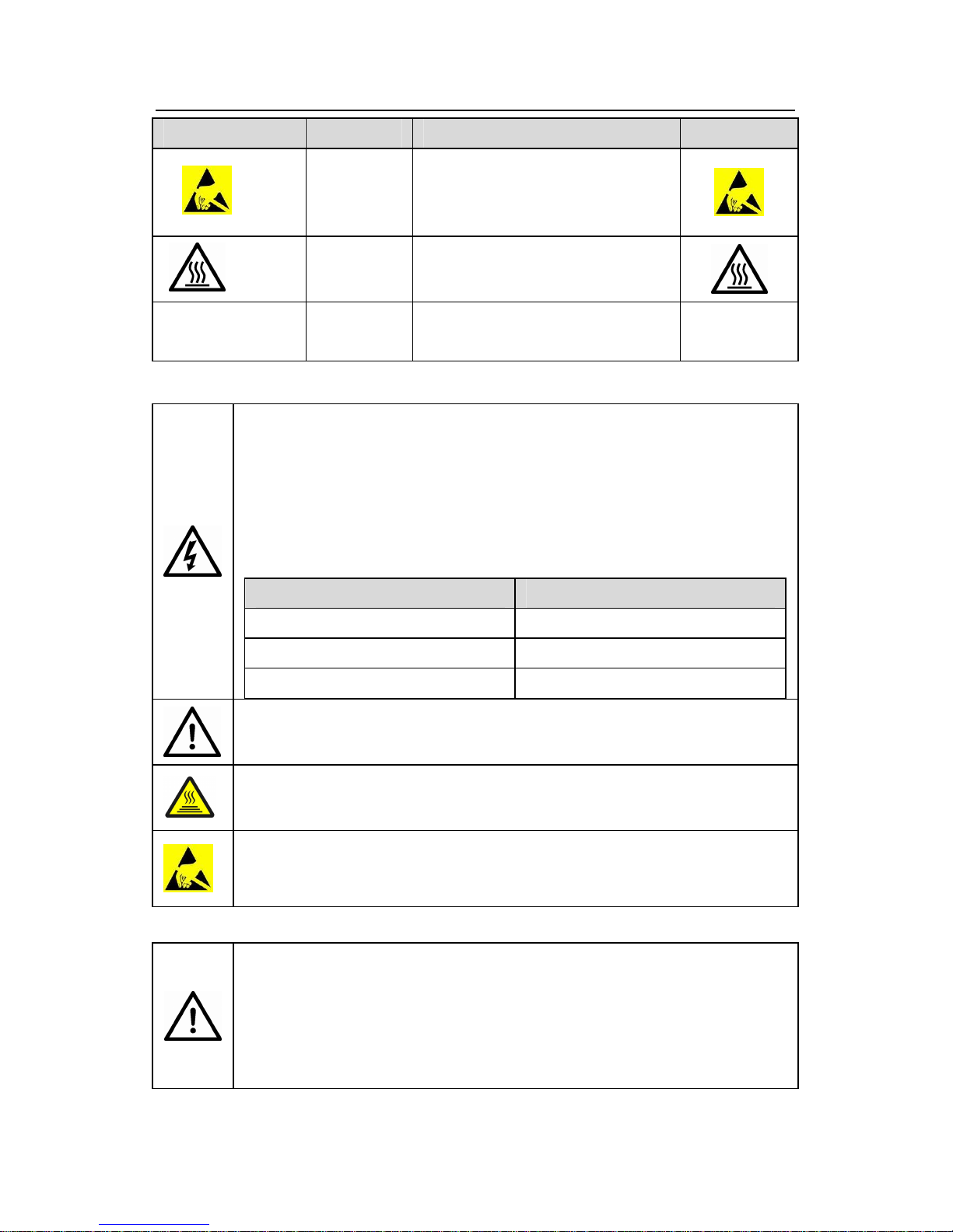
Symbols Name Instruction Abbreviation
Do not
Electrostatic
discharge
Damage to the PCBA board may
occur if not follow the relative
requirements
Hot sides
Hot sides
Sides of the device may become
hot. Do not touch.
Note
Note
Physical hurt may occur if not follow
the relative requirements
Note
1.4 Safety guidelines
Only qualified electricians are allowed to operate on the inverter.
Do not carry out any wiring and inspection or changing components when the
power supply is applied. Ensure all input power supply is disconnected
before wiring and checking and always wait for at least the time designated
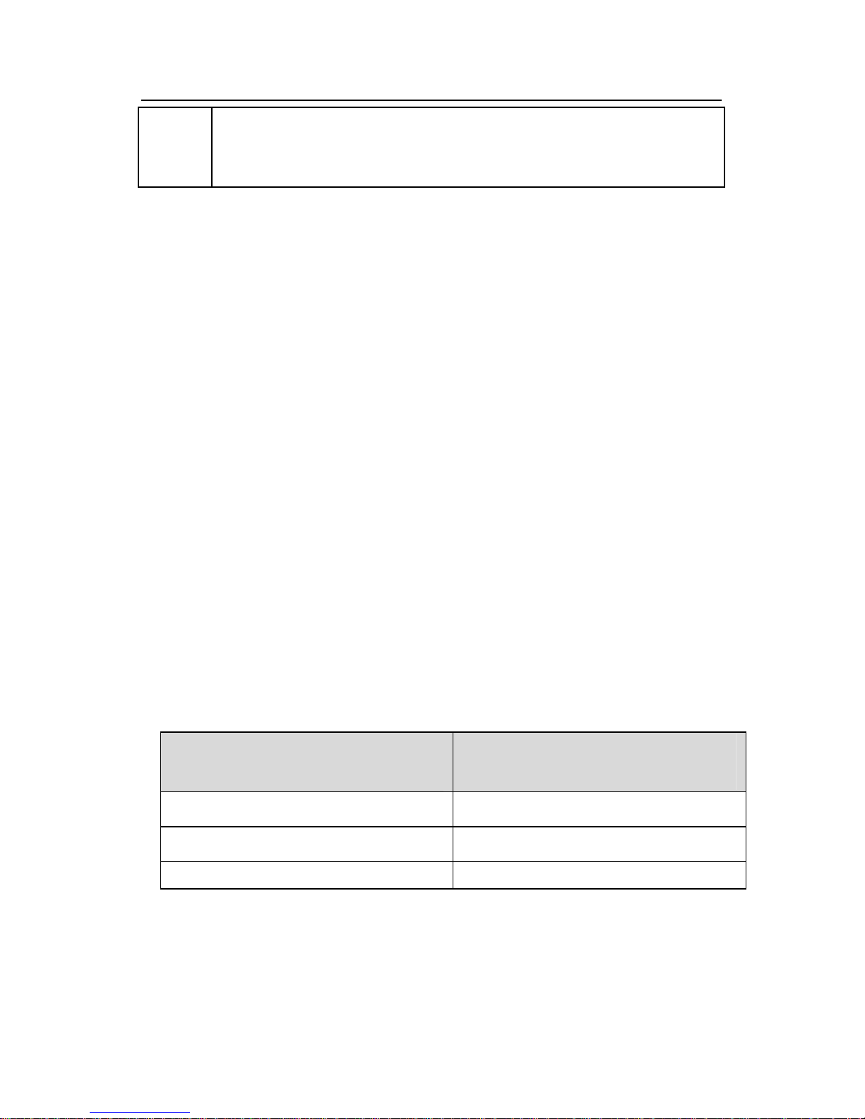
on the inverter or until the DC bus voltage is less than 36V. Below is the table
of the waiting time:
Inverter module Minimum waiting time
400V 1.5kW-110kW 5 minutes
400V 132 kW -315 kW 15 minutes
400V above 350 kW 25 minutes
Do not refit the inverter unauthorizedly; otherwise fire, electric shock or other
injury may occur.
The base of the radiator may become hot during running. Do not touch to
avoid hurt.
The electrical parts and components inside the inverter are electrostatic. Take
measurements to avoid electrostatic discharge during relevent operation.
1.4.1 Delivery and installation
Please install the inverter on fire-retardant material and keep the inverter
away from combustible materials.
Connect the braking optional parts (braking resistors, braking units or
feedback units) according to the wiring diagram.
Do not operate on the inverter if there is any damage or components loss to
Page 9
Goodrive300 inverters Safety precautions
8
the inverter.
Do not touch the inverter with wet items or body, otherwise electric shock
may occur.
Note:
Select appropriate moving and installing tools to ensure a safe and normal running of
the inverter and avoid physical injury or death. For physical safety, the erector should
take some mechanical protective measurements, such as wearing exposure shoes
and working uniforms.
Ensure to avoid physical shock or vibration during delivery and installation.
Do not carry the inverter by its cover. The cover may fall off.
Install away from children and other public places.
The inverter cannot meet the requirements of low voltage protection in IEC61800-5-1
if the sea level of installation site is above 2000m.
Please use the inverter on appropriate condition (See chapter Installation
Environment).
Don't allow screws, cables and other conductive items to fall inside the inverter.
The leakage current of the inverter may be above 3.5mA during operation. HIGH
LEAKAGE CURRENT, EARTH CONNECTION ESSENTIAL BEFORE CONNECTING
SUPPLY. Ground with proper techniques and ensure the grounding resistor is less
than 10Ω. The conductivity of PE grounding conductor is the same as that of the
phase conductor (with the same cross sectional area).
Grounding conductors minimum cross-sectional area of at least 10mm2, or the
corresponding data in the table below, the maximum being asked to choose between
the two cross-sectional area as the grounding conductor:
Power line conductor cross-sectional area
mm2
Grounding conductor cross-sectional area
mm2
S≤16
S
16<S≤35
16
35<S S/2
R, S and T are the input terminals of the power supply, while U, V and W are the motor
terminals. Please connect the input power cables and motor cables with proper
techniques; otherwise the damage to the inverter may occur.
Page 10
Goodrive300 inverters Safety precautions
9
1.4.2 Commission and running
Disconnect all power supplies applied to the inverter before the terminal
wiring and wait for at least the designated time after disconnecting the
power supply.
High voltage is present inside the inverter during running. Do not carry
out any operation except for the keypad setting.
The inverter may start up by itself when P01.21=1. Do not get close to
the inverter and motor.
The inverter can not be used as “Emergency-stop device”.
The inverter can not be used to break the motor suddenly. A mechanical
braking device should be provided.
Besides the above items, check to ensure the following ones before the
installation and maintenance during the running of the permanent
synchronization motor:
1. All input power supply is disconnected (including the main power
supply and the control power supply).
2. The permanent magnet synchronization motor has stopped
running and measured to ensure the output voltage of the inverter
is less than 36V.
3. The waiting time of the permanent magnet synchronization motor
after stopping is no less than the time designated and measure to
ensure the voltage between + and – is less than 36V.
4. Ensure the permanent magnet synchronization motor does not
rotate again because of the external load. It is recommended to
install effectively external braking devices or disconnect the electric
wiring between the motor and the inverter directly.
Note:
Do not switch on or off the input power supply of the inverter frequently.
For inverters that have been stored for a long time, check and fix the capacitance and
try to run it again before utilization (see Maintenance and Hardware Fault
Diagnose).
Cover the front board before running, otherwise electric shock may occur.
Page 11
Goodrive300 inverters Safety precautions
10
1.4.3 Maintenance and replacement of components
Only qualified electricians are allowed to perform the maintenance,
inspection, and components replacement of the inverter.
Disconnect all power supplies to the inverter before the terminal wiring.
Wait for at least the time designated on the inverter after disconnection.
Take measures to avoid screws, cables and other conductive matters to
fall into the inverter during maintenance and component replacement.
Note:
Please select proper torque to tighten screws.
Keep the inverter, parts and components away from combustible materials during
maintenance and component replacement.
Do not carry out any isolation and pressure test on the inverter and do not measure
the control circuit of the inverter by megameter.
Carry out a sound anti-electrostatic protection to the inverter and its internal
components during maintenance and component replacement.
1.4.4 What to do after scrapping
There are heavy metals in the inverter. Deal with it as industrial effluent.
Page 12
Goodrive300 inverters Quick start-up
11
Quick Start-up 2
2.1 What this chapter contains
This chapter mainly describes the basic guidelines during the installation and commission
procedures on the inverter, which you may follow to install and commission the inverter
quickly.
2.2 Unpacking inspection
Check as followings after receiving products:
1. Check that there are no damage and humidification to the package. If not, please contact
with local agents or INVT offices.
2. Check the information on the type designation label on the outside of the package to
verify that the drive is of the correct type. If not, please contact with local dealers or INVT
offices.
3. Check that there are no signs of water in the package and no signs of damage or breach
to the inverter. If not, please contact with local dealers or INVT offices.
4. Check the information on the type designation label on the outside of the package to
verify that the name plate is of the correct type. If not, please contact with local dealers or
INVT offices.
5. Check to ensure the accessories (including user’s manual, control keypad and extension
card) inside the device is complete. If not, please contact with local dealers or INVT offices.
2.3 Application confirmation
Check the machine before beginning to use the inverter:
1. Check the load type to verify that there is no overload of the inverter during work and
check that whether the drive needs to modify the power degree.
2. Check that the actual current of the motor is less than the rated current of the inverter.
3. Check that the control accuracy of the load is the same of the inverter.
4. Check that the incoming supply voltage is correspondent to the rated voltage of the
inverter.
5. Check that the communication needs option card or not.
Page 13
Goodrive300 inverters Quick start-up
12
2.4 Environment
Check as followings before the actual installation and usage:
1. Check that the ambient temperature of the inverter is below 40 . If exceeds, derate℃ 3%
for every additional 1 . ℃ Additionally, the inverter can not be used if the ambient
temperature is above 50℃.
Note: for the cabinet inverter, the ambient temperature means the air temperature inside
the cabinet.
2. Check that the ambient temperature of the inverter in actual usage is above -10℃. If not,
add heating facilities.
Note: for the cabinet inverter, the ambient temperature means the air temperature inside
the cabinet.
3. Check that the altitude of the actual usage site is below 1000m. If exceeds, derate1% for
every additional 100m.
4. Check that the humidity of the actual usage site is below 90% and condensation is not
allowed. If not, add additional protection inverters.
5. Check that the actual usage site is away from direct sunlight and foreign objects can not
enter the inverter. If not, add additional protective measures.
6. Check that there is no conductive dust or flammable gas in the actual usage site. If not,
add additional protection to inverters.
2.5 Installation confirmation
Check as followings after the installation:
1. Check that the load range of the input and output cables meet the need of actual load.
2. Check that the accessories of the inverter are correctly and properly installed. The
installation cables should meet the needs of every component (including reactors, input
filters, output reactors, output filters, DC reactors, braking units and braking resistors).
3. Check that the inverter is installed on non-flammable materials and the calorific
accessories (reactors and brake resistors) are away from flammable materials.
4. Check that all control cables and power cables are run separately and the routation
complies with EMC requirement.
5. Check that all grounding systems are properly grounded according to the requirements
of the inverter.
6. Check that the free space during installation is sufficient according to the instructions in
user’s manual.
Page 14
Goodrive300 inverters Quick start-up
13
7. Check that the installation conforms to the instructions in user’s manual. The drive must
be installed in an upright position.
8. Check that the external connection terminals are tightly fastened and the torque is
appropriate.
9. Check that there are no screws, cables and other conductive items left in the inverter. If
not, get them out.
2.6 Basic commission
Complete the basic commissioning as followings before actual utilization:
1. Select the motor type, set correct motor parameters and select control mode of the
inverter according to the actual motor parameters.
2. Autotune. If possible, de-coupled from the motor load to start dynamic autotune. Or if not,
static autotune is available.
3. Adjust the ACC/DEC time according to the actual running of the load.
4. Commission the device via jogging and check that the rotation direction is as required. If
not, change the rotation direction by changing the wiring of motor.
5. Set all control parameters and then operate.
Page 15
Goodrive300 inverters Product overview
14
Product Overview 3
3.1 What this chapter contains
The chapter briefly describes the operation principle, product characteristics, layout, name
plate and type designation information.
3.2 Basic principles
Goodrive300 series inverters are wall or flange mountable devices for controlling
asynchronous AC induction motors and permanent magnet synchronous motors.
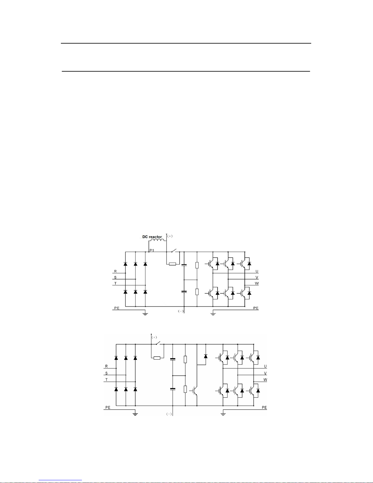
The diagram below shows the simplified main circuit diagram of the inverter. The rectifier
converts three-phase AC voltage to DC voltage. The capacitor bank of the intermediate
circuit stabilizes the DC voltage. The converter transforms the DC voltage back to AC
voltage for the AC motor. The brake pipe connects the external braking resistor to the
intermediate DC circuit to consume the feedback energy when the voltage in the circuit
exceeds its maximum limit.
Diagram 3-1 The simplified main circuit diagram (above 37kW (including 37kW))
Diagram 3-2 The simplified main circuit diagram (below 30kW (including 30kW))
Page 16
Goodrive300 inverters Product overview
15
Note:
1. The inverter above 37kW (including 37kW) supports external DC reactor which is an
optional part. Before connecting, it is necessary to remove the copper row between P1
and(+).
2. The inverter below 30kW (including 30kW) supports external braking resistor; the inverter
above 37kW (including 37kW) supports external braking units. Both the braking unit and the
braking resistor are optional parts.
3.3 Product specification
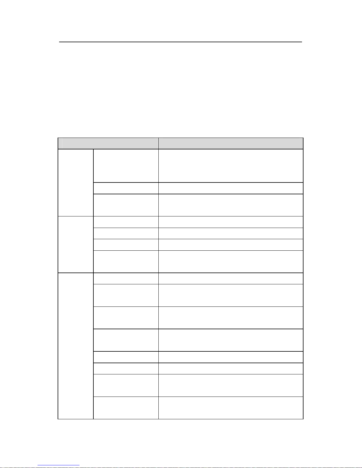
Function Specification
Input voltage (V)
AC 3PH 400V±15%
AC 3PH 220V±10%
AC 3PH 660V±10%
Input current (A) Refer to the rated value
Power
input
Input frequency (Hz)
50Hz or 60Hz
Allowed range: 47~63Hz
Output voltage (V) 0~input voltage
Output current (A) Refer to the rated value
Output power (kW) Refer to the rated value
Power
output
Output frequency
(Hz)
0~400Hz
Control mode V/F, sensorless vector control
Motor type
Asynchronous motor and permanent magnet
synchronous motor
Adjustable-speed
ratio
Asynchronous motor 1:200 (SVC) synchronous
motor 1:20 (SVC)
Speed control
accuracy
±0.2% (sensorless vector control)
Speed fluctuation
± 0.3%(sensorless vector control)
Torque response <20ms(sensorless vector control)
Torque control
accuracy
10%(sensorless vector control)
Technical
control
feature
Starting torque Asynchronous motor: 0.25Hz/150%(sensorless
vector control)
Page 17
Goodrive300 inverters Product overview
16
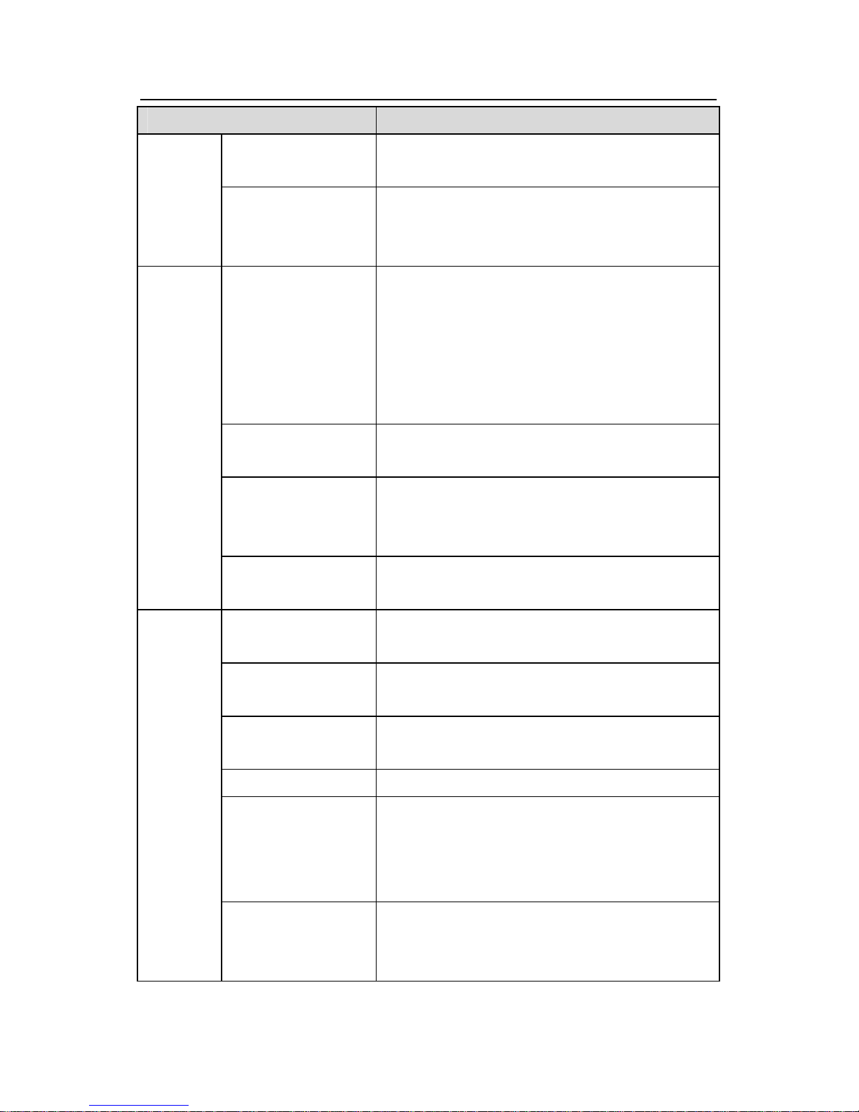
Function Specification
Synchronous motor: 2.5 Hz/150%(sensorless vector
control)
Overload capability
150% of rated current: 1 minute
180% of rated current: 10 seconds
200% of rated current: 1 second
Frequency setting
method
Digital setting, analog setting, pulse frequency
setting, multi-stage speed running setting, simple
PLC setting, PID setting, MODBUS communication
setting, PROFIBUS communication setting.
Realize the shifting between the set combination
and set channel.
Auto-adjustment of
the voltage
Keep a stable voltage automatically when the grid
voltage transients
Fault protection
Provide over 30 fault protection functions:
overcurrent, overvoltage, undervoltage, overheating,
phase loss and overload, etc.
Running
control
feature
Restart after rotating
speed tracking
Realize the smooth starting of the rotating motor
Terminal analog input
resolution
Not above 20mV
Terminal switch input
resolution
Not above 2ms
Analog input
2 ways (AI1, AI2) 0~10V/0~20mA and 1 way (AI3)
-10~10V
Analog output 2 ways (AO1, AO2) 0~10V /0~20mA
Digital input
8 ways common input, the Max. frequency: 1kHz,
internal impedance: 3.3kΩ;
1 way high speed input, the Max. frequency:
50kHz
Peripheral
interface
Digital output
1way high speed pulse output, the Max. frequency:
50kHz;
1way Y terminal open collector pole output
Page 18
Goodrive300 inverters Product overview
17
Function Specification
Relay output
2 ways programmable relay output
RO1A NO, RO1B NC, RO1C common terminal
RO2A NO, RO2B NC, RO2C common terminal
Contactor capability: 3A/AC250V,1A/DC30V
Mountable method Wall, flange and floor mountable
Temperature of the
running environment
-10~50℃, derate above 40℃
Average non-fault
time
2 years (25℃ ambient temperature)
Protective degree IP20
Cooling Air-cooling
Braking unit
Built in braking unit for below 30kW (including
30kW)
External braking unit for others
Others
EMC filter
Built-in C3 filter: meet the degree requirement of
IEC61800-3 C3
External filter:meet the degree requirement of
IEC61800-3 C2
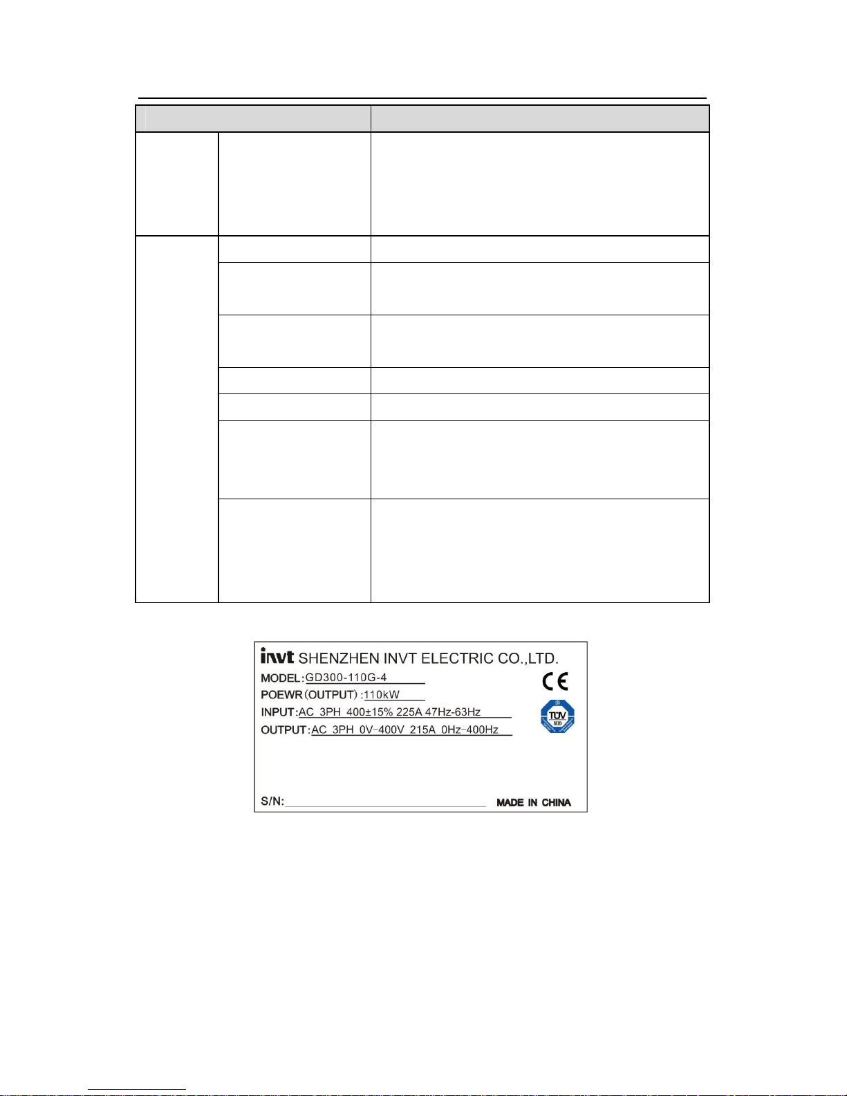
3.4 Nameplate
Fig 3-3 Name plate
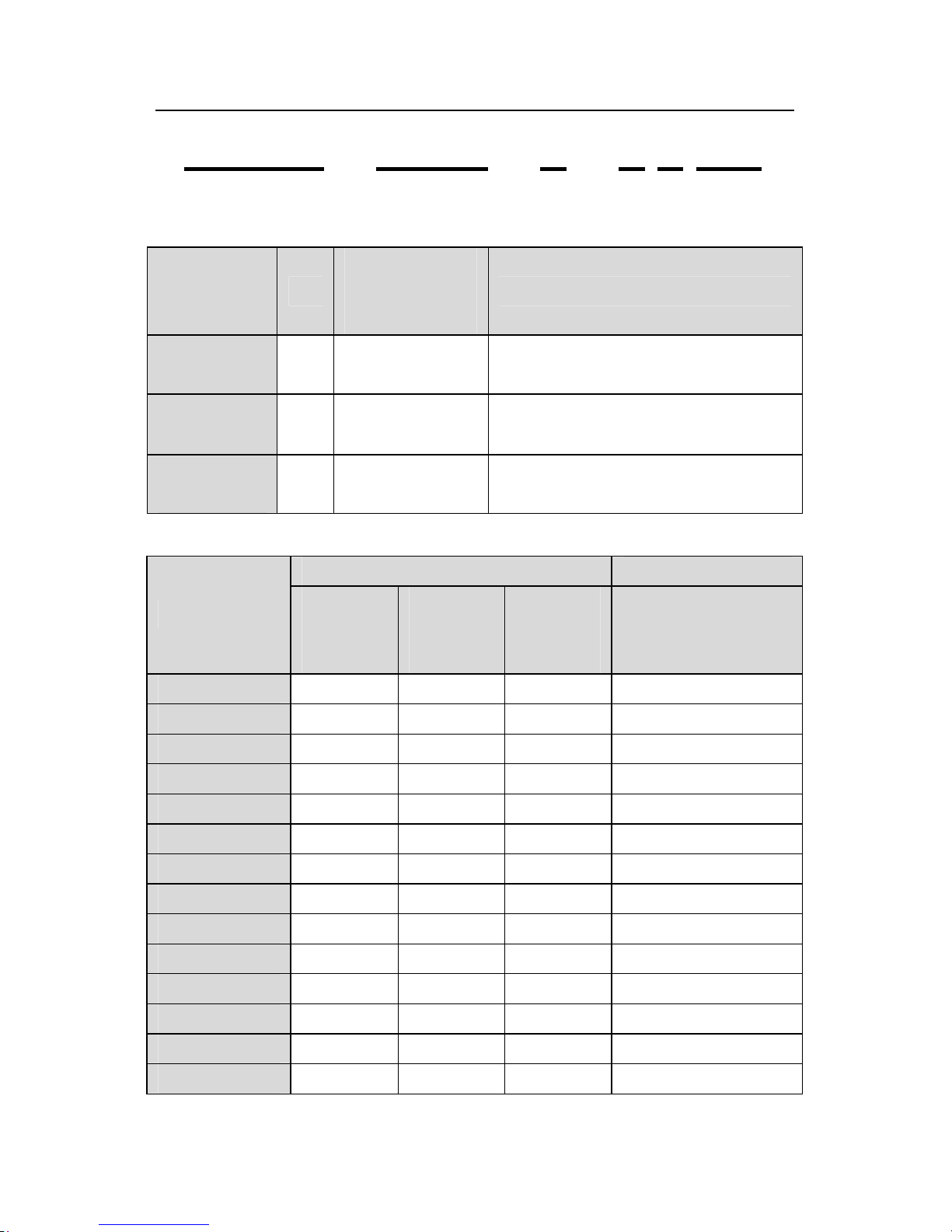
3.5 Type designation key
The type designation contains information on the inverter. The user can find the type
designation on the type designation label attached to the inverter or the simple name plate.
Page 19
Goodrive300 inverters Product overview
18
GD300 – 5R5G – 4 – 2 T * *
① ② ③ ④ ⑤ ⑥
Fig 3-4 Product type
Field
identification
Sign
Detailed
description of the
sign
Detailed content
Abbreviation
①
Product
abbreviation
Goodrive300 is shorted for GD300.
Rated power
②
Power range +
Load type
5R5-5.5kW
G—Constant torque load
Voltage
degree
③ Voltage degree 400V
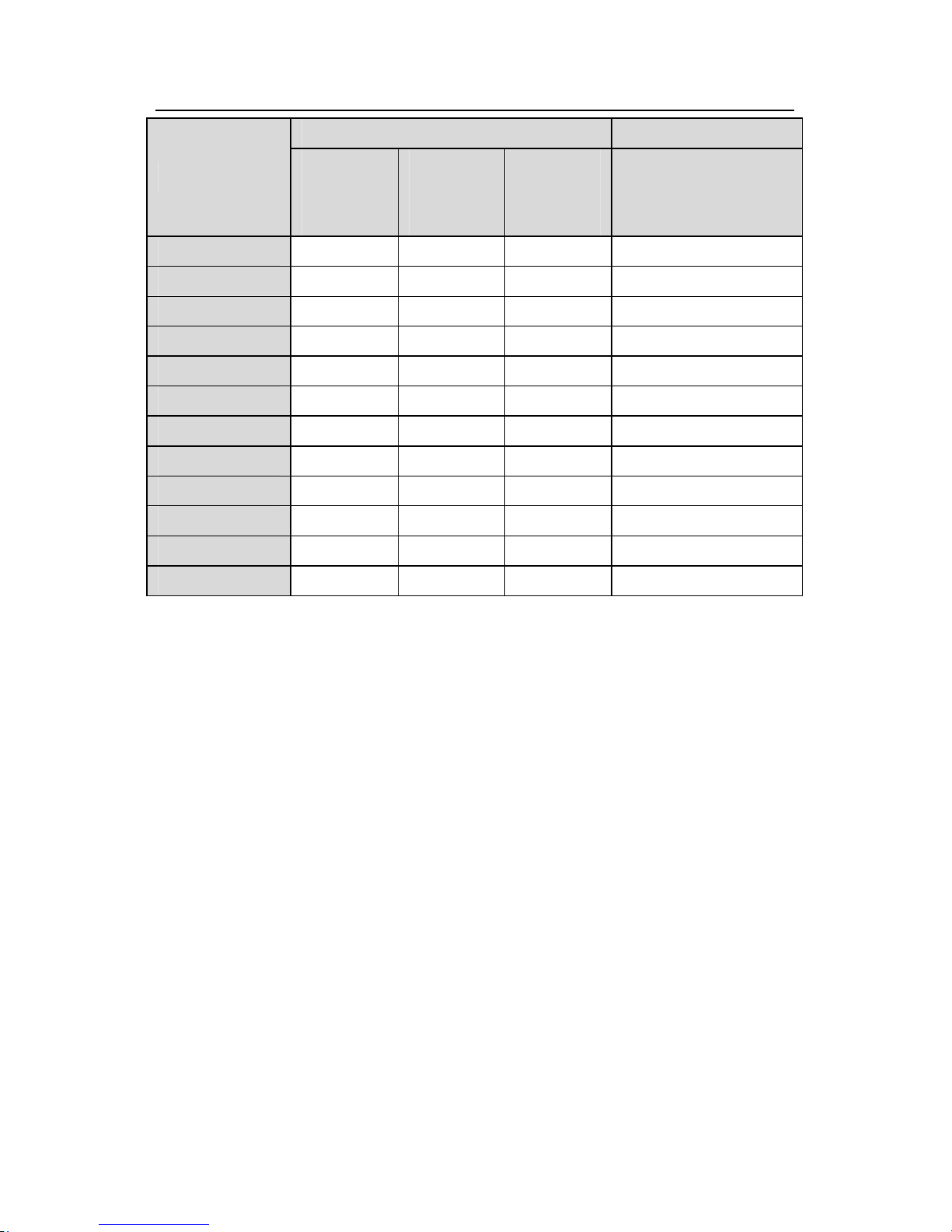
3.6 Rated specifications
Constant torque Weight(Kg)
The inverter
Rated
output
power (A)
Rated
input
current (A)
Rated
output
current (A)
Weight(Kg)
GD300-1R5G-4
1.5 5.0 3.7 1.5
GD300-2R2G-4
2.2 5.8 5 2.2
GD300-004G-4 4 13.5 9.5 4
GD300-5R5G-4
5.5 19.5 14 5.5
GD300-7R5G-4
7.5 25 18.5 7.5
GD300-011G-4 11 32 25 11
GD300-015G/-4
15 40 32 15
GD300-018G-4 18.5 47 38 18.5
GD300-022G-4 22 56 45 22
GD300-030G-4 30 70 60 30
GD300-037G-4 37 80 75 37
GD300-045G-4 45 94 92 45
GD300-055G-4 55 128 115 55
GD300-075G-4 75 160 150 75
Page 20
Goodrive300 inverters Product overview
19
Constant torque Weight(Kg)
The inverter
Rated
output
power (A)
Rated
input
current (A)
Rated
output
current (A)
Weight(Kg)
GD300-090G-4 90 190 180 90
GD300-110G-4 110 225 215 110
GD300-132G-4 132 265 260 132
GD300-160G-4 160 310 305 160
GD300-200G-4 200 385 380 200
GD300-220G-4 220 430 425 220
GD300-250G-4 250 485 480 250
GD300-280G-4 280 545 530 280
GD300-315G-4 315 610 600 315
GD300-350G-4 350 625 650 350
GD300-400G-4 400 715 720 400
GD300-500G-4 500 890 860 500
Note:
1. The input current of 1.5~315kW inverters is measured when the input voltage is 380V and
configured without DC reactor and input/output filter.
2. The input current of 350~500kW inverters is measured when the input voltage is 380V
and configured with input reactor.
3. The output current is defined as the output current when the output voltage is 380V.
Note: the inverter is configured LED keypad. The LCD keypad is optional with various
functions. The installation is compatible with that of the LED keypad.
Note: M3 nuts and the bracket can be used directly in the installation. The keypad bracket is
optional for 1.5~30kW inverters and configured for 37~500kW inverters.
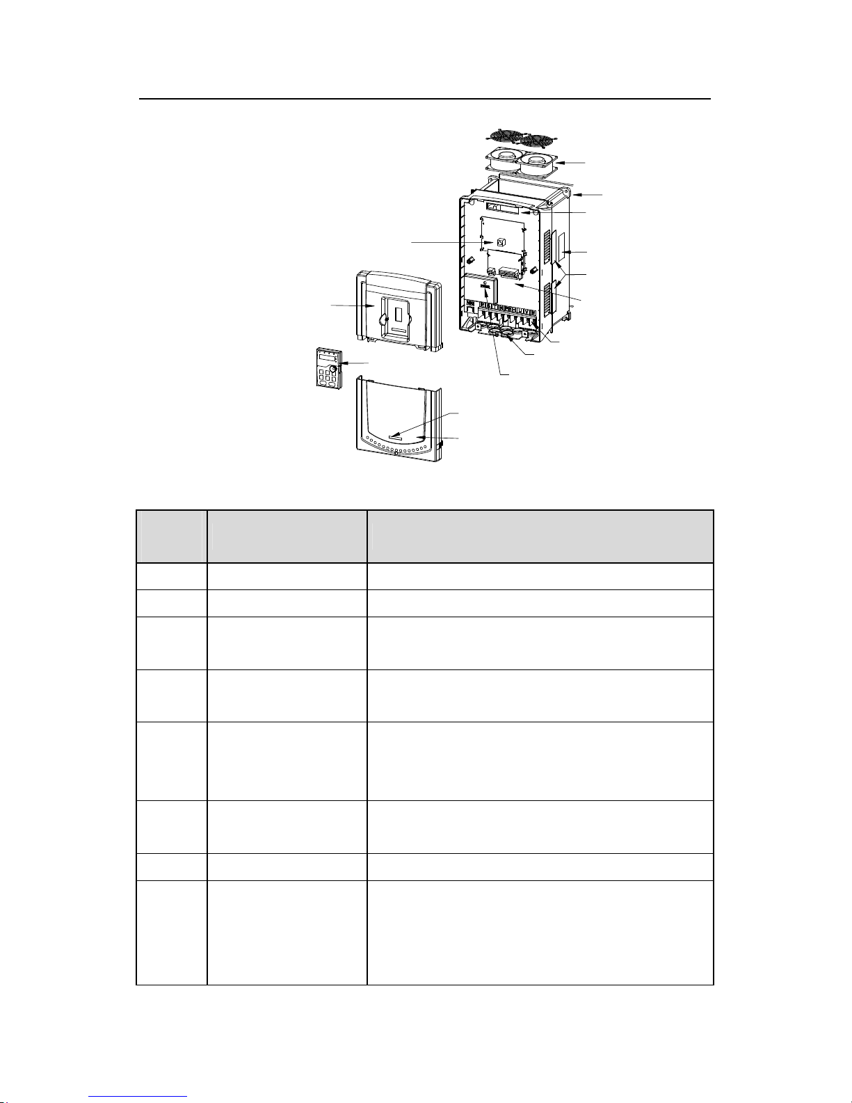
3.7 Structure diagram
Below is the layout figure of the inverter (take the inverter of 30kW as the example).
Page 21
Goodrive300 inverters Product overview
20
4
6
7
1
2
3
14
13
9
10
11
12
8
5
Fig 3-5 Product structure diagram
Serial
No.
Name Illustration
1 Keypad connections Connect the keypad
2 Upper cover Protect the internal parts and components
3 Keypad
See Keypad Operation Procedure for detailed
information
4 Cooling fan
See Maintenance and Hardware Fault Diagnose for
detailed information
5 Cardboard
The cardboard, with installation holes, is the same as
the behind cover of the machine and, so it is
convenient for the installation.
6
Wire arrangement
interface
Connect to the control board and the drive board
7 Name plate See Product Overview for detailed information
8 Side cover
Optional part. The side cover will increase the
protective degree of the inverter. The internal
temperature of the inverter will increase, too, so it is
necessary to derate the inverter at the same time
Page 22
Goodrive300 inverters Product overview
21
Serial
No.
Name Illustration
9 Control terminals See Electric Installation for detailed information
10 Main circuit terminals See Electric Installation for detailed information
11 Main circuit cable entry Fix the main circuit cable
12 POWER light Power indicator
13 Simple name plate See Product Overview for detailed information
14 Lower cover Protect the internal parts and components
Page 23
Goodrive300 inverters Installation guidelines
22
Installation Guidelines 4
4.1 What this chapter contains
The chapter describes the mechanical installation and electric installation.
Only qualified electricians are allowed to carry out what described in this
chapter. Please operate as the instructions in Safety Precautions. Ignoring
these may cause physical injury or death or damage to the devices.
Ensure the power supply of the inverter is disconnected during the operation.
Wait for at least the time designated until the POWER indicator is off after the
disconnection if the power supply is applied. It is recommended to use the
multimeter to monitor that the DC bus voltage of the drive is under 36V.
The installation and design of the inverter should be complied with the
requirement of the local laws and regulations in the installation site. If the
installation infringes the requirement, our company will exempt from any
responsibility. Additionally, if users do not comply with the suggestion, some
damage beyond the assured maintenance range may occur.
4.2 Mechanical installation
4.2.1 Installation environment
The installation environment is the safeguard for a full performance and long-term stable
functions of the inverter. Check the installation environment as followings:
Environment Conditions
Installation site Indoor
Environment
temperature
-10~+50℃
If the ambient temperature of the inverter is above 40 , derate 3% ℃
for every additional 1 . ℃
It is not recommended to use the inverter if the ambient
temperature is above 50 . ℃
In order to improve the reliability of the device, do not use the
inverter if the ambient temperature changes frequently.
Please provide cooling fan or air conditioner to control the internal
ambient temperature below the required one if the inverter is used
Page 24
Goodrive300 inverters Installation guidelines
23
Environment Conditions
in a close space such as in the control cabinet.
When the temperature is too low, if the inverter needs to restart to
run after a long stop, it is necessary to provide an external heating
device to increase the internal temperature, otherwise damage to
the devices may occur.
Humidity
RH≤90%
No condensation is allowed.
The maximum relative humility should be equal to or less than
60% in corrosive air.
Storage
temperature
-30~+60℃
Running
environment
condition
The installation site of the inverter should:
keep away from the electromagnetic radiation source;
keep away from contaminative air, such as corrosive gas, oil mist
and flammable gas;
ensure foreign objects, such as metal power, dust, oil, water can
not enter into the inverter(do not install the inverter on the
flammable materials such as wood);
keep away from direct sunlight, oil mist, steam and vibration
environment.
Altitude
Below 1000m
If the sea level is above 1000m, please derate 1% for every
additional 100m.
Vibration ≤ 5.88m/s2(0.6g)
Installation direction
The inverter should be installed on an upright position to ensure
sufficient cooling effect.
Note:
Goodrive300 series inverters should be installed in a clean and ventilated
environment according to enclosure classification.
Cooling air must be clean, free from corrosive materials and electrically conductive
dust.
Page 25
Goodrive300 inverters Installation guidelines
24
4.2.2 Installation direction
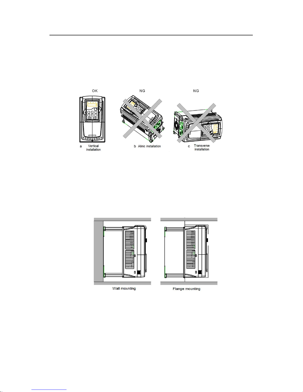
The inverter may be installed on the wall or in a cabinet.
The inverter must be installed in an upright position. Check the installation site according to
the requirements below. Refer to chapter Dimension Drawings in the appendix for frame
details.
Fig 4-1 Installation direction of the inverter
4.2.3 Installation manner
The inverter can be installed in three different ways, depending on the frame size:
a) Wall mounting (≤315kW)
b) Flange mounting (≤200kW)
c) Floor mounting (220kW-500k)
Fig 4-2 Installation manner
(1)Mark the hole location. The location of the holes is shown in the dimension drawings in
the appendix.
(2)Fix the screws or bolts to the marked locations..
(3)Position the drive onto the wall.
(4)Tighten the screws in the wall securely.
Page 26
Goodrive300 inverters Installation guidelines
25
Note: the flange installation of 1.5~30kW inverters need flange board, while the flange
installation of 37~200kW inverters do not need.
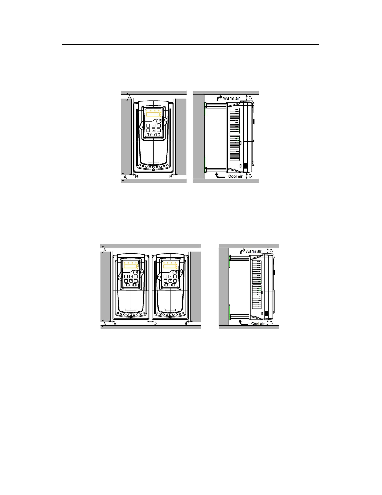
4.2.4 Single installation
Fig 4-3 Single installation
Note:The minimum space of B and C is 100mm.
4.2.5 Multiple installations
Parallel installation
Fig 4-4 Parallel installation
Note:
Before installing the different sizes inverters,please align their top position for the
convenience of later maintenance.
The minimum space of B, D and C is 100mm.
Page 27
Goodrive300 inverters Installation guidelines
26
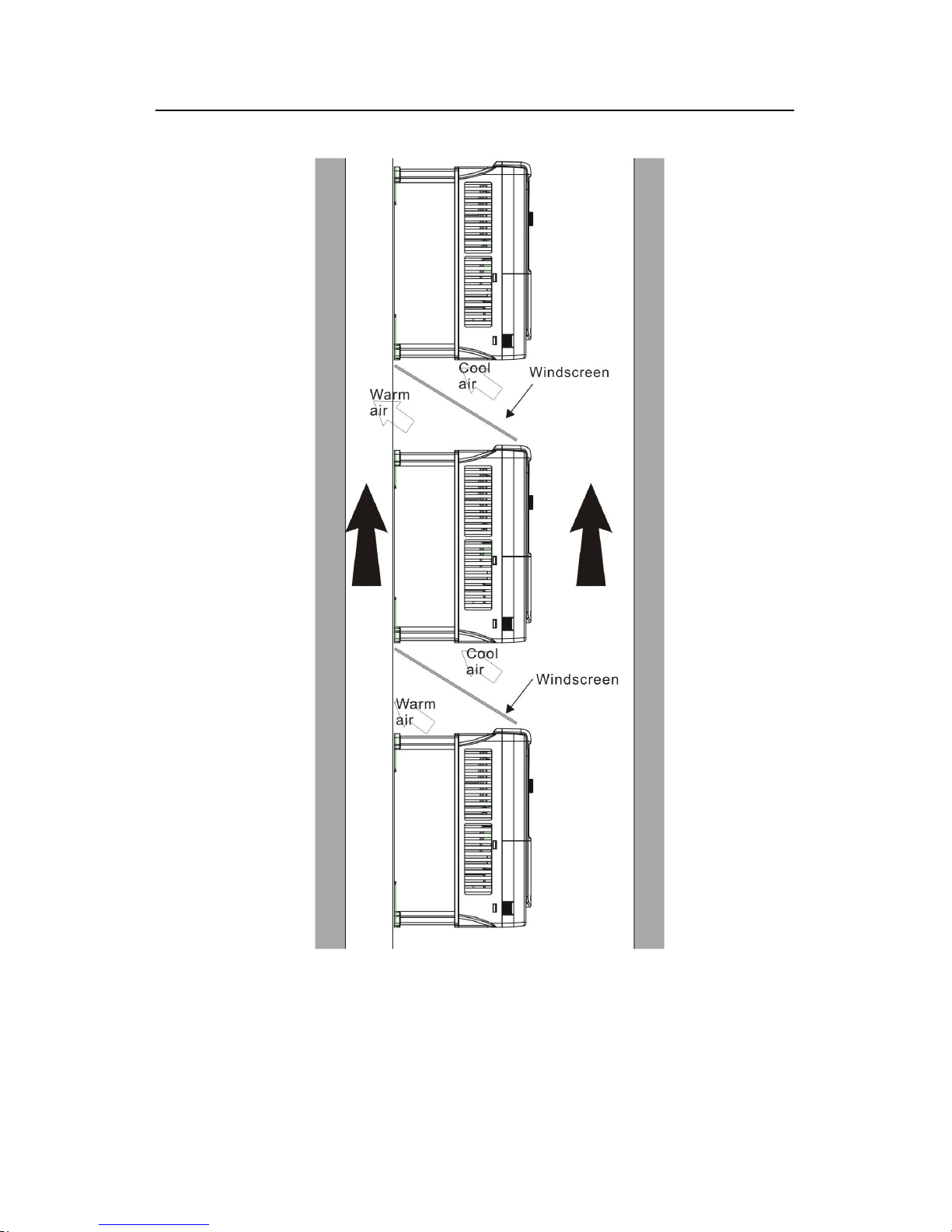
4.2.6 Vertical installation
Fig 4-5 Vertical installation
Note: Windscreen should be added in Vertical installation for avoiding mutual impact and
insufficient cooling.
Page 28
Goodrive300 inverters Installation guidelines
27
4.2.7 Tilt installation
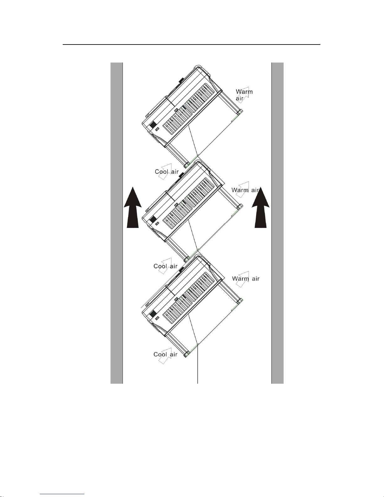
Fig 4-6 Tilt installation
Note: Ensure the separation of the wind input and output channels in tilt installation for
avoiding mutual impact.
Page 29
Goodrive300 inverters Installation guidelines
28
4.3 Standard wiring
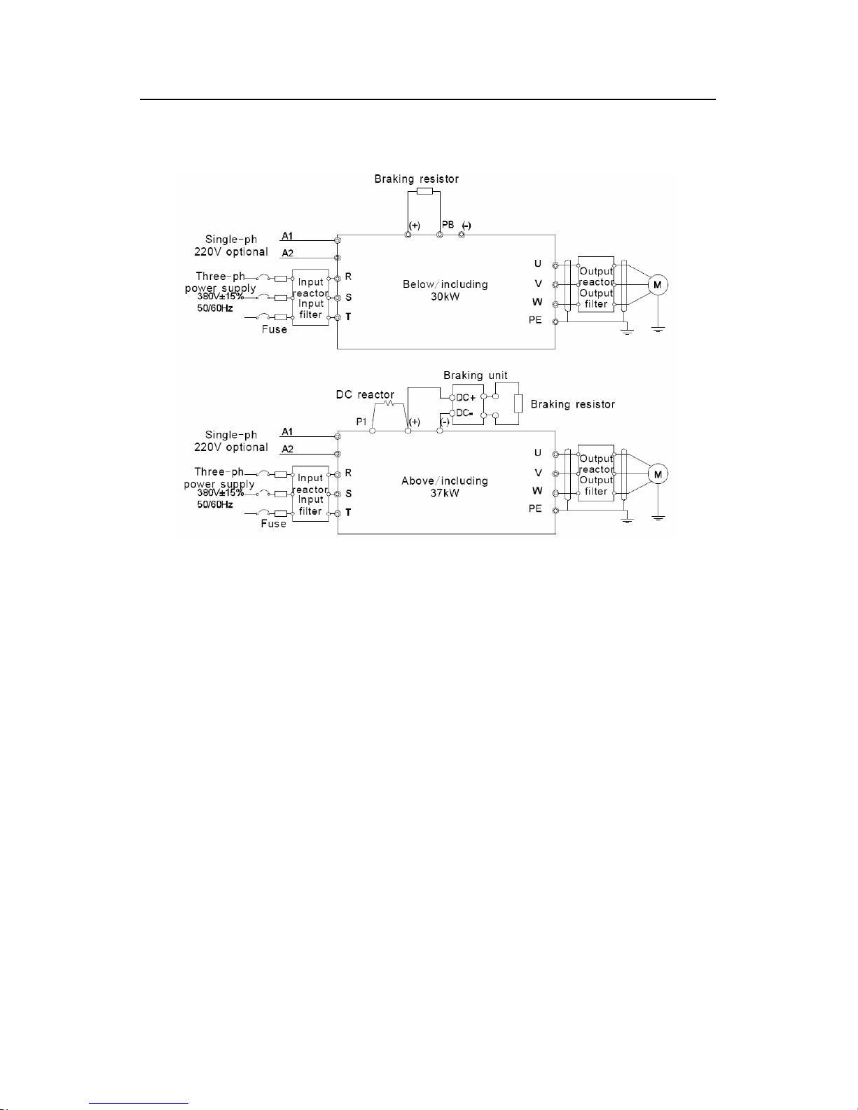
4.3.1 Connection diagram of main circuit
Diagram 4-7 Connection diagram of main circuit
Note:
The fuse, DC reactor, braking unit, braking resistor, input reactor, input filter, output
reactor, output filter are optional parts. Please refer to Peripheral Optional Parts for
detailed information.
A1 and A2 are optional parts.
P1 and (+) are short circuited in factory, if need to connect with the DC rector, please
remove the contact tag between P1 and (+).
Page 30
Goodrive300 inverters Installation guidelines
29
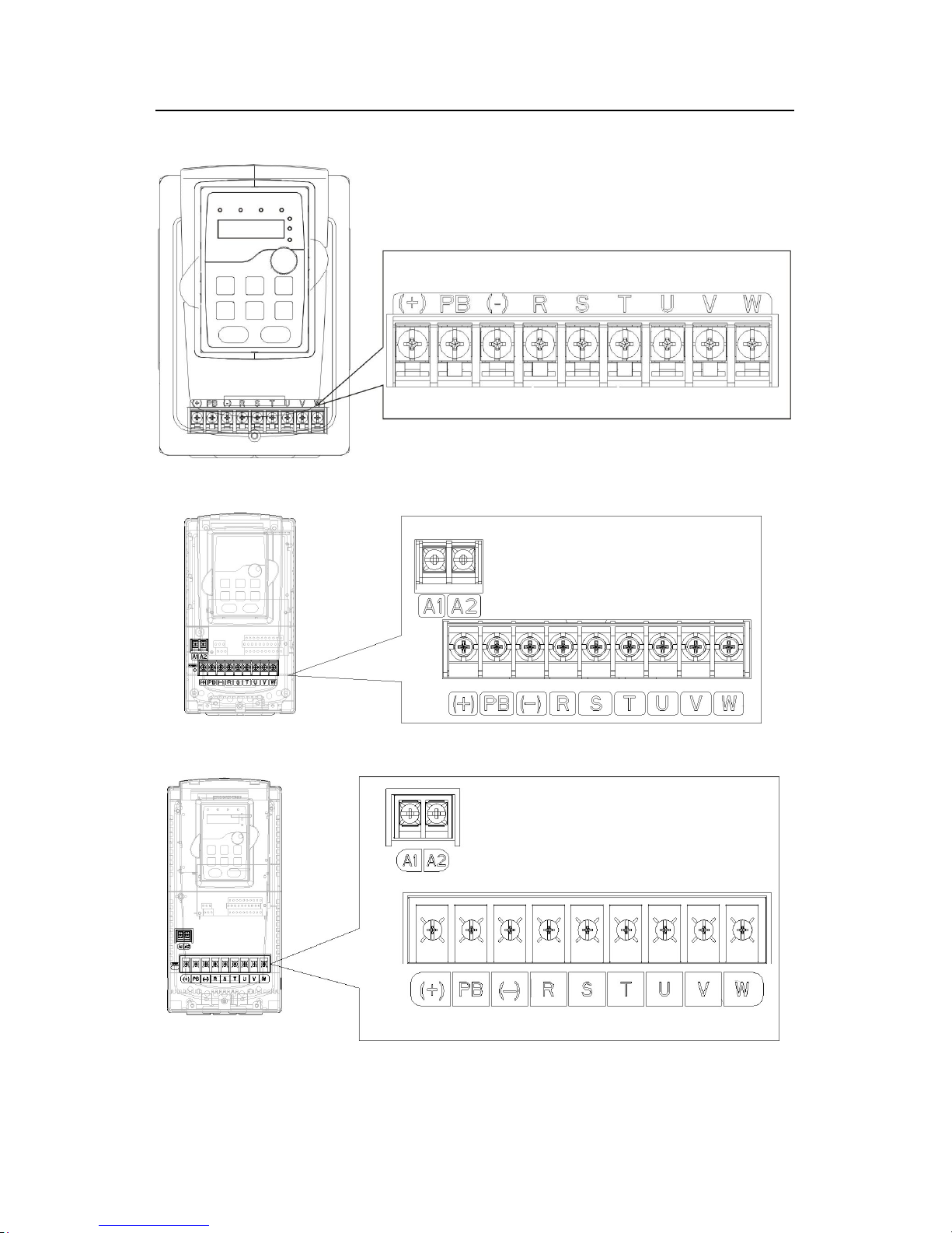
4.3.2 Terminals figure of main circuit
Fig 4-8 1.5~2.2 kW terminals of main circuit
Fig 4-9 4~5.5 kW terminals of main circuit
Fig 4-10 7.5~11kW terminals of main circuit
Page 31
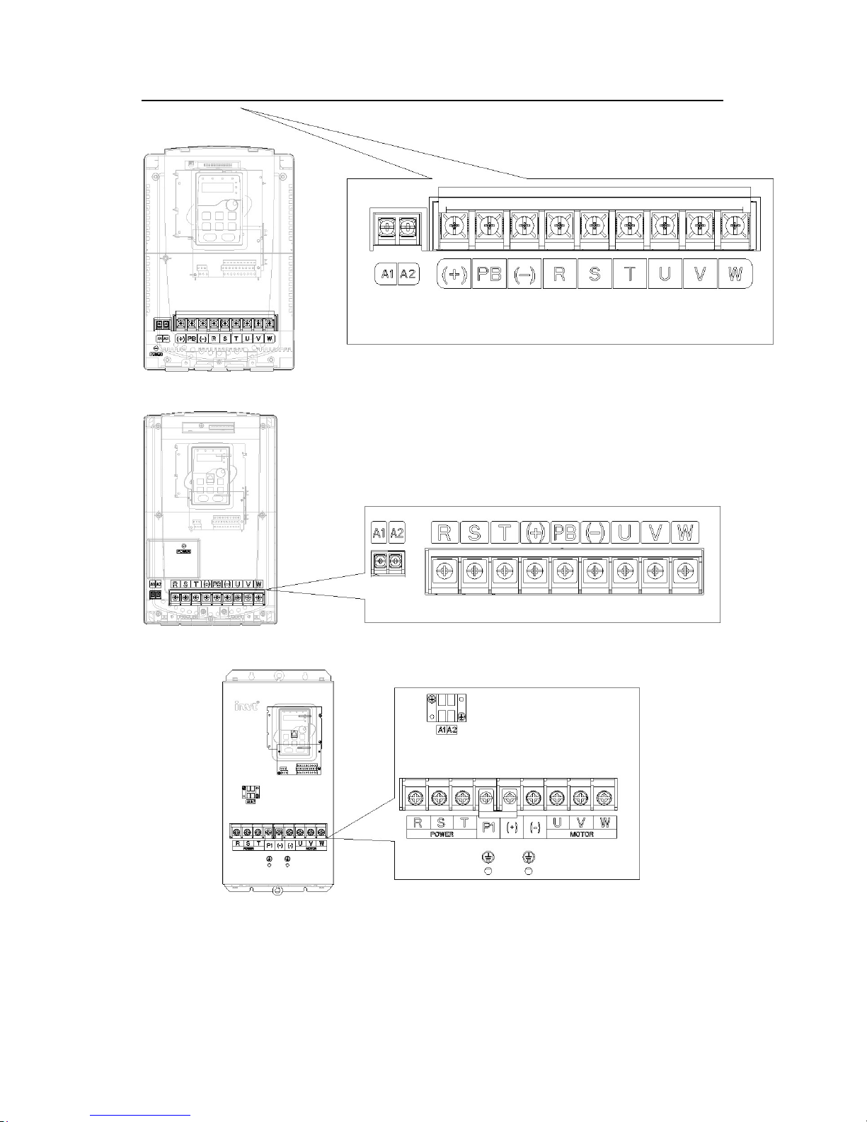
Goodrive300 inverters Installation guidelines
30
Fig 4-11 15~18kW terminals of main circuit
Fig 4-12 22~30kW terminals of main circuit
Fig 4-13 37~55 kW terminals of main circuit
Page 32
Goodrive300 inverters Installation guidelines
31
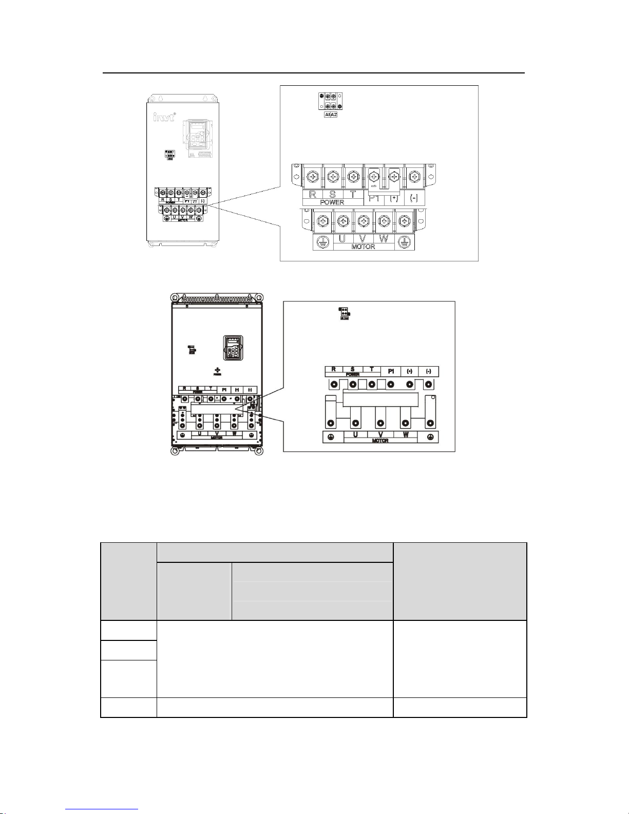
Fig 4-14 75~110kW terminals of main circuit
Fig 4-15 132~315kW terminals of main circuit
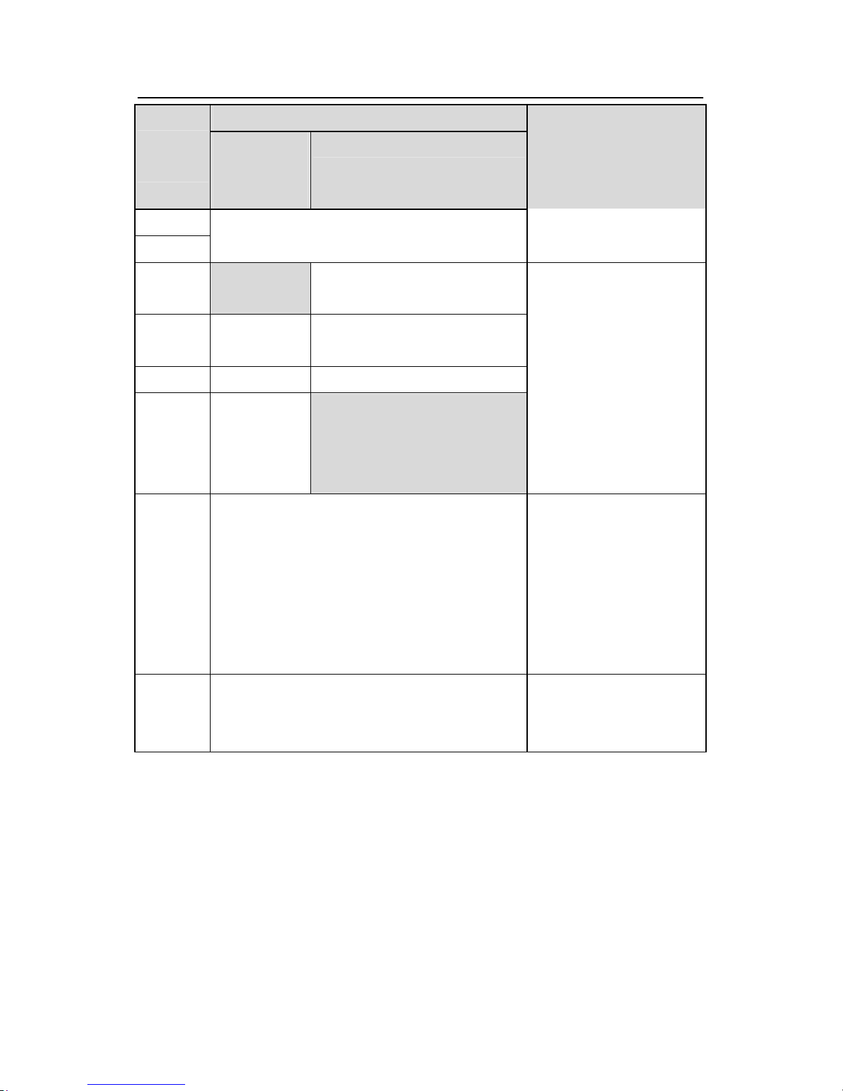
Terminal name
Terminal
sign
Below 30kW
(including 30
kW)
Above 37kW(including 37 kW)
Function
R
S
T
Power input of the main circuit
3-
phase AC input terminals
which are generally
connected with the
power
supply.
U The inverter output 3-phase AC output terminals
Page 33
Goodrive300 inverters Installation guidelines
32
Terminal name
Terminal
sign
Below 30kW
(including 30
kW)
Above 37kW(including 37 kW)
Function
V
W
which are
generally
connected with the motor.
P1
This terminal is
inexistent
DC reactor terminal 1
(+)
Braking
resistor
1
DC reactor terminal 2
, braking unit
terminal 1
(-) / Braking unit terminal 2
PB
Braking
resistor 2
This terminal is inexistent.
P1 and (+)
are connected
with the terminals of DC
reactor.
(+) and (-)
are connected
with the terminals of
braking
unit.
PB and (+)
are connected
with the terminals of braking
resistor.
PE 400V:the grounding resistor is less than 10Ohm
Protective grounding
terminals, every machine
is
provided 2 PE terminals
as
the standard
configuration.
These terminals should be
grounded with proper
techniques.
A1 and A2
Control power supply terminal
Optional parts (external
220V control power
supply)
Note:
Do not use an asymmetrically constructed motor cable. If there is a symmetrically
constructed grounding conductor in the motor cable in addition to the conductive
shield, connect the grounding conductor to the grounding terminal at the inverter
and motor ends.
Braking resistor, braking unit and DC reactor are optional parts.
Route the motor cable, input power cable and control cables separately.
If the terminal is not appeared, the machine does not provide the terminal as the
Page 34
Goodrive300 inverters Installation guidelines
33
external terminal.
4.3.3 Wiring of terminals in main circuit
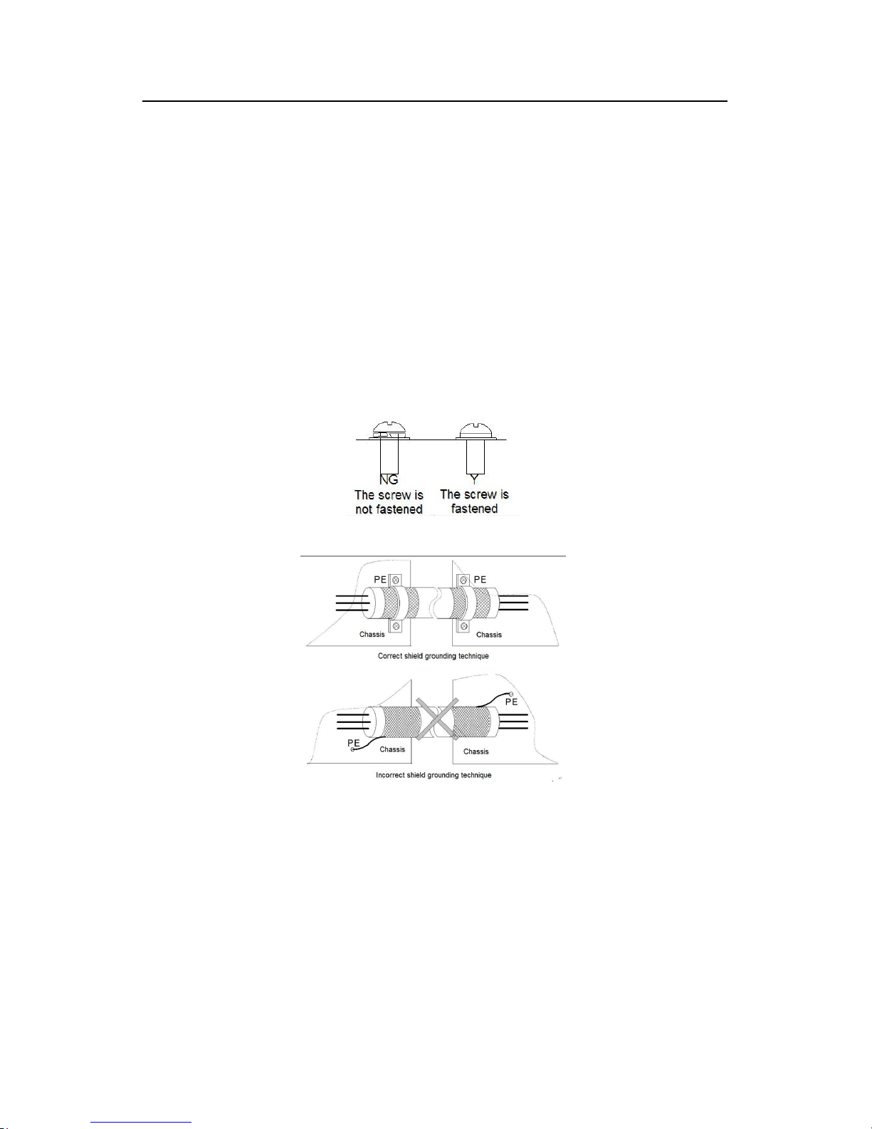
1. Fasten the grounding conductor of the input power cable with the grounding terminal of
the inverter (PE) by 360 degree grounding technique. Connect the phase conductors to R, S
and T terminals and fasten.
2. Strip the motor cable and connect the shield to the grounding terminal of the inverter by
360 degree grounding technique. Connect the phase conductors to U, V and W terminals
and fasten.
3. Connect the optional brake resistor with a shielded cable to the designated position by the
same procedures in the previous step.
4. Secure the cables outside the inverter mechanically.
Fig 4-14 Correct installation of the screw
Fig 4-15 360 degree grounding technique
Page 35
Goodrive300 inverters Installation guidelines
34
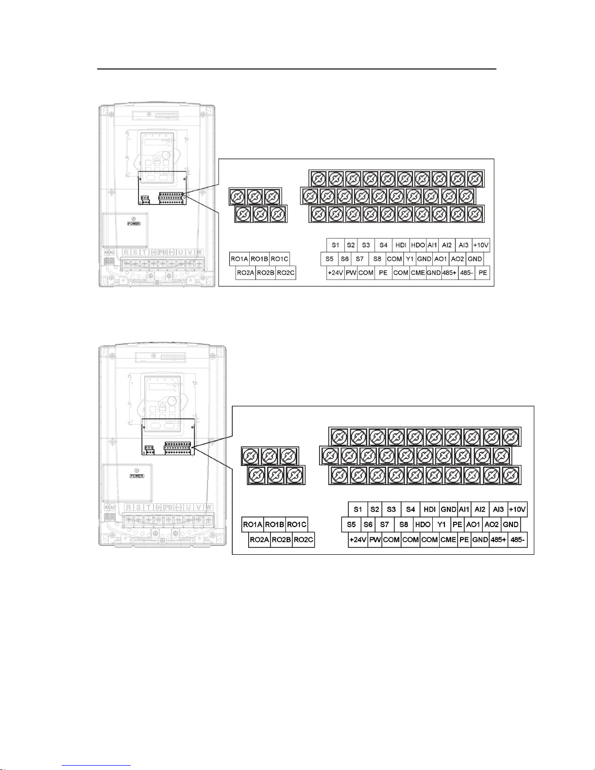
4.3.4 Wiring diagram of control circuit
Fig 4-18 Wiring of control circuit
4.3.5 Terminals of control circuit
Fig 4-17 Terminals of control circuit
Page 36
Goodrive300 inverters Installation guidelines
35
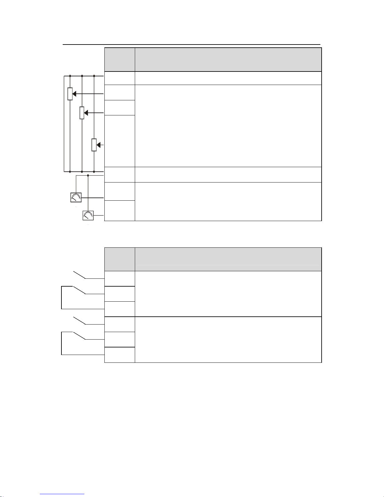
Terminal
name
Description
+10V
Local power supply +10V
AI1
AI2
AI3
1. Input range: AI1/AI2 voltage and current can be chose:
0~10V/0~20mA;AI1 can be shifted by J1;
AI2 can be shifted by J2
AI3:-10V~+10V
2. Input impedance:voltage input: 20kΩ; current input: 500Ω
3. Resolution: the minimum one is 5mV when 10V corresponds to
50Hz
4. Deviation ±1%, 25℃
GND +10V reference null potential
AO1
AO2
1. Output range:0~10V or -20~20mA
2. The voltage or the current output is depended on the jumper
3. Deviation±1%,25℃
Terminal
name
Description
RO1A
RO1B
RO1C
RO1 relay output, RO1A NO, RO1B NC, RO1C common terminal
Contactor capability: 3A/AC250V,1A/DC30V
RO2A
RO2B
RO2C
RO2 relay output, RO2A NO, RO2B NC, RO2C common terminal
Contactor capability: 3A/AC250V,1A/DC30V
Page 37
Goodrive300 inverters Installation guidelines
36
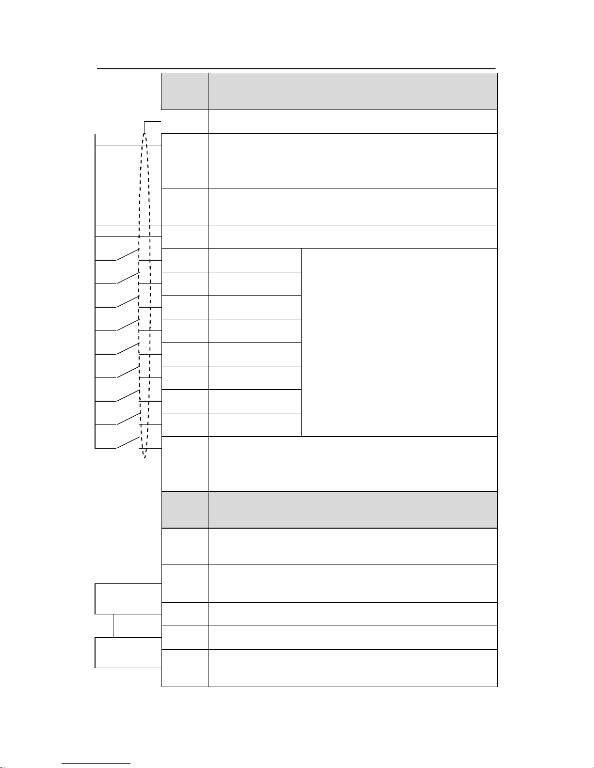
Terminal
name
Description
PE
Grounding terminal
PW
Provide the input switch working power supply from external to
internal.
Voltage range: 12~24V
24V
The inverter provides the power supply for users with a maximum
output current of 200mA
COM +24V common terminal
S1 Switch input 1
S2 Switch input 2
S3 Switch input 3
S4 Switch input 4
S5 Switch input 5
S6 Switch input 6
S7 Switch input 7
S8 Switch input 8
1. Internal impedance:3.3kΩ
2. 12~30V voltage input is available
3. The terminal is the dual-direction input
terminal supporting both NPN and PNP
4. Max input frequency:1kHz
5. All are programmable digital input
terminal. User can set the terminal function
through function codes.
HDI
Except for S1~S8, this terminal can be used as high frequency
input channel.
Max. input frequency:50kHz
Terminal
name
Description
24V
The inverter provides the power supply for users with a maximum
output current of 200mA
HDO
1. Switch input:200mA/30V
2. Output frequency range:0~50kHz
COM
+24V common terminal
CME
Common terminal of the open collector pole output
Y
1.Swtich capability:200mA/30V
2.Output frequency range:0~1kHz
Page 38
Goodrive300 inverters Installation guidelines
37
485+
485-
485 communication interface and 485 differential signal interface
If it is the standard 485 communication interface, please use
twisted pairs or shield cable.
4.3.6 Input /Output signal connection figure
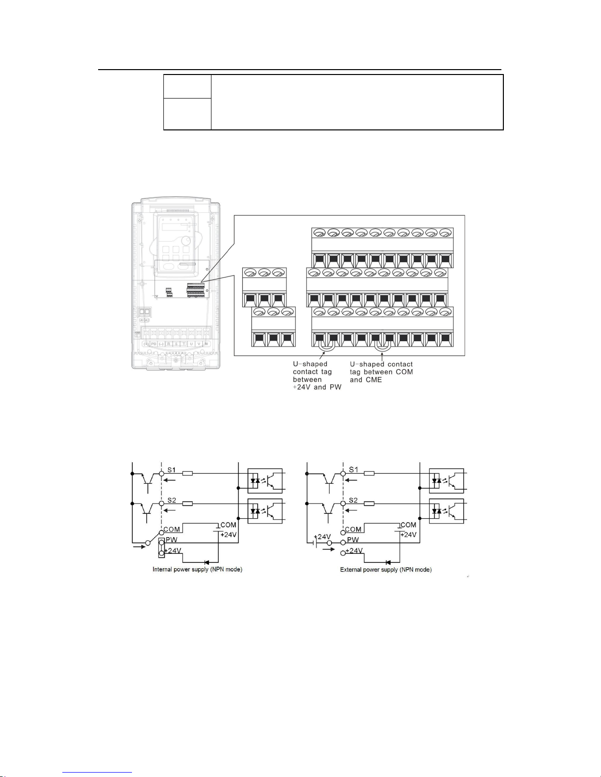
Please use U-shaped contact tag to set NPN mode or PNP mode and the internal or external
power supply. The default setting is NPN internal mode.
Fig 4-18 U-shaped contact tag
If the signal is from NPN transistor, please set the U-shaped contact tag between +24V and
PW as below according to the used power supply.
Diagram 4-19 NPN modes
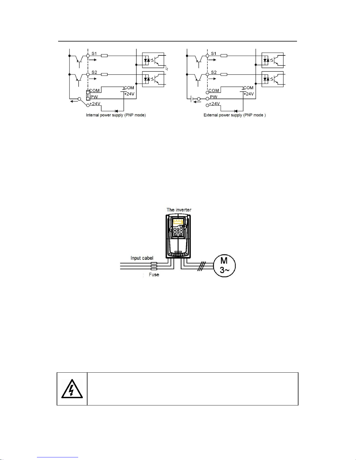
If the signal is from PNP transistor, please set the U-shaped contact tag as below according
to the used power supply.
Page 39
Goodrive300 inverters Installation guidelines
38
Diagram 4-20 PNP modes
4.4 Layout protection
4.4.1 Protecting the inverter and input power cable in short-circuit situations
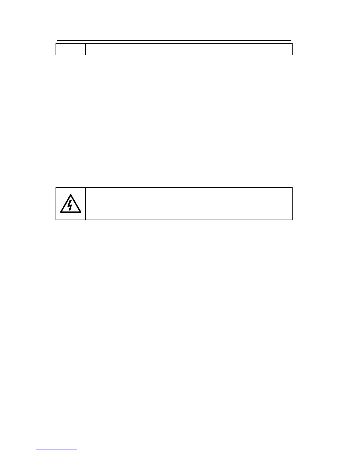
Protect the inverter and input power cable in short circuit situations and against thermal
overload.
Arrange the protection according to the following guidelines.
Fig 4-16 Fuse configuration
Note: Select the fuse as the manual indicated. The fuse will protect the input power cable
from damage in short-circuit situations. It will protect the surrounding devices when the
internal of the inverter is short circuited.
4.4.2 Protecting the motor and motor cable in short-circuit situations
The inverter protects the motor and motor cable in a short-circuit situation when the motor
cable is dimensioned according to the rated current of the inverter. No additional protection
devices are needed.
If the inverter is connected to multiple motors, a separate thermal
overload switch or a circuit breaker must be used for protecting each
cable and motor. These devices may require a separate fuse to cut off
Page 40
Goodrive300 inverters Installation guidelines
39
the short-circuit current.
4.4.3 Protecting the motor against thermal overload
According to regulations, the motor must be protected against thermal overload and the
current must be switched off when overload is detected. The inverter includes a motor
thermal protection function that protects the motor and closes the output to switch off the
current when necessary.
4.4.4 Implementing a bypass connection
It is necessary to set power frequency and variable frequency conversion circuits for the
assurance of continuous normal work of the inverter if faults occur in some significant
situations.
In some special situations, for example, if it is only used in soft start, the inverter can be
conversed into power frequency running after starting and some corresponding bypass
should be added.
Never connect the supply power to the inverter output terminals U, V
and W. Power line voltage applied to the output can result in permanent
damage to the inverter.
If frequent shifting is required, employ mechanically connected switches or contactors to
ensure that the motor terminals are not connected to the AC power line and inverter output
terminals simultaneously.
Page 41
Goodrive300 inverters Keypad operation procedure
40
Keypad Operation Procedure 5
5.1 What this chapter contains
This chapter contains following operation:
• Buttons, indicating lights and the screen as well as the methods to inspect, modify and
set function codes by keypad
• Start-up
5.2 Keypad
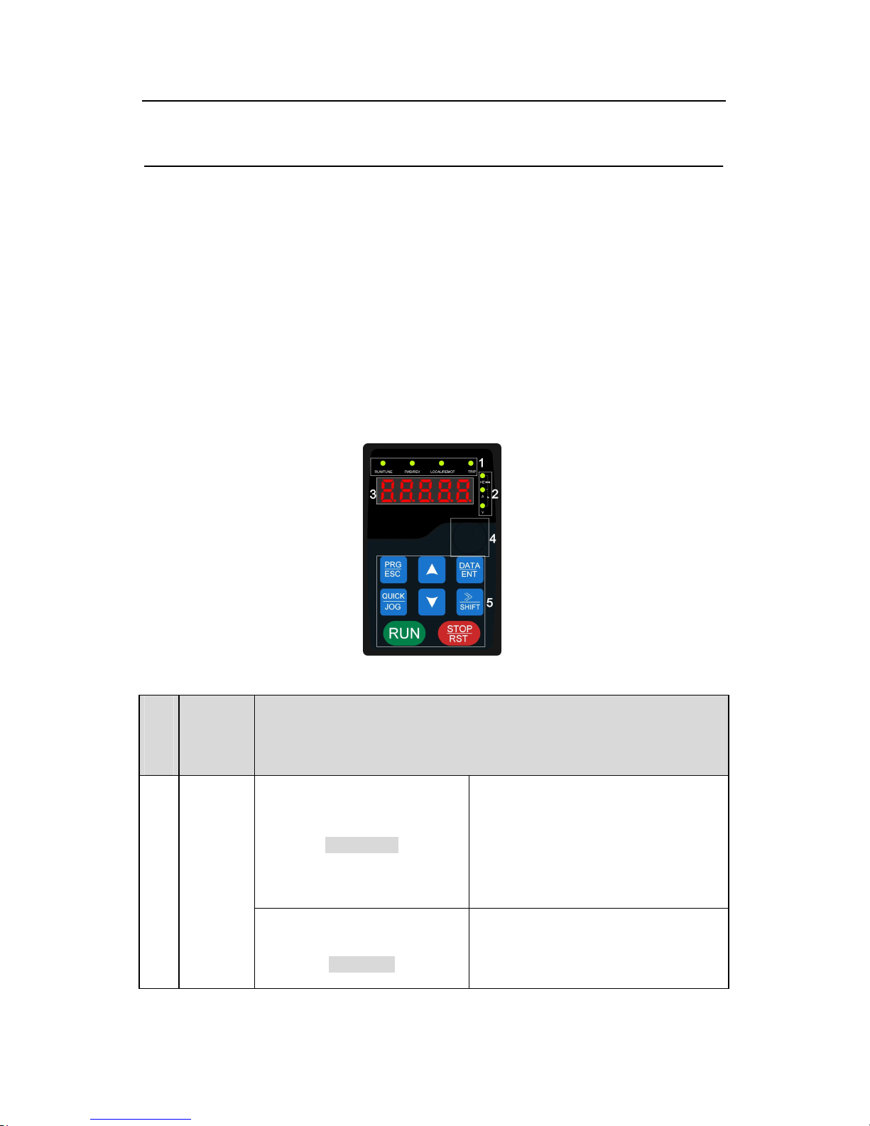
The keypad is used to control Goodrive300 series inverters, read the state data and adjust
parameters.
Fig 5-1 Keypad
Seri
al
No.
Name
Description
RUN/TUNE
LED off means that the inverter is in the
stopping state; LED blinking means the
inverter is in the parameter autotune
state; LED on means the inverter is in
the running state.
1 State LED
FWD/REV
FED/REV LED
LED off means the inverter is in the
forward rotation state; LED on means
Page 42
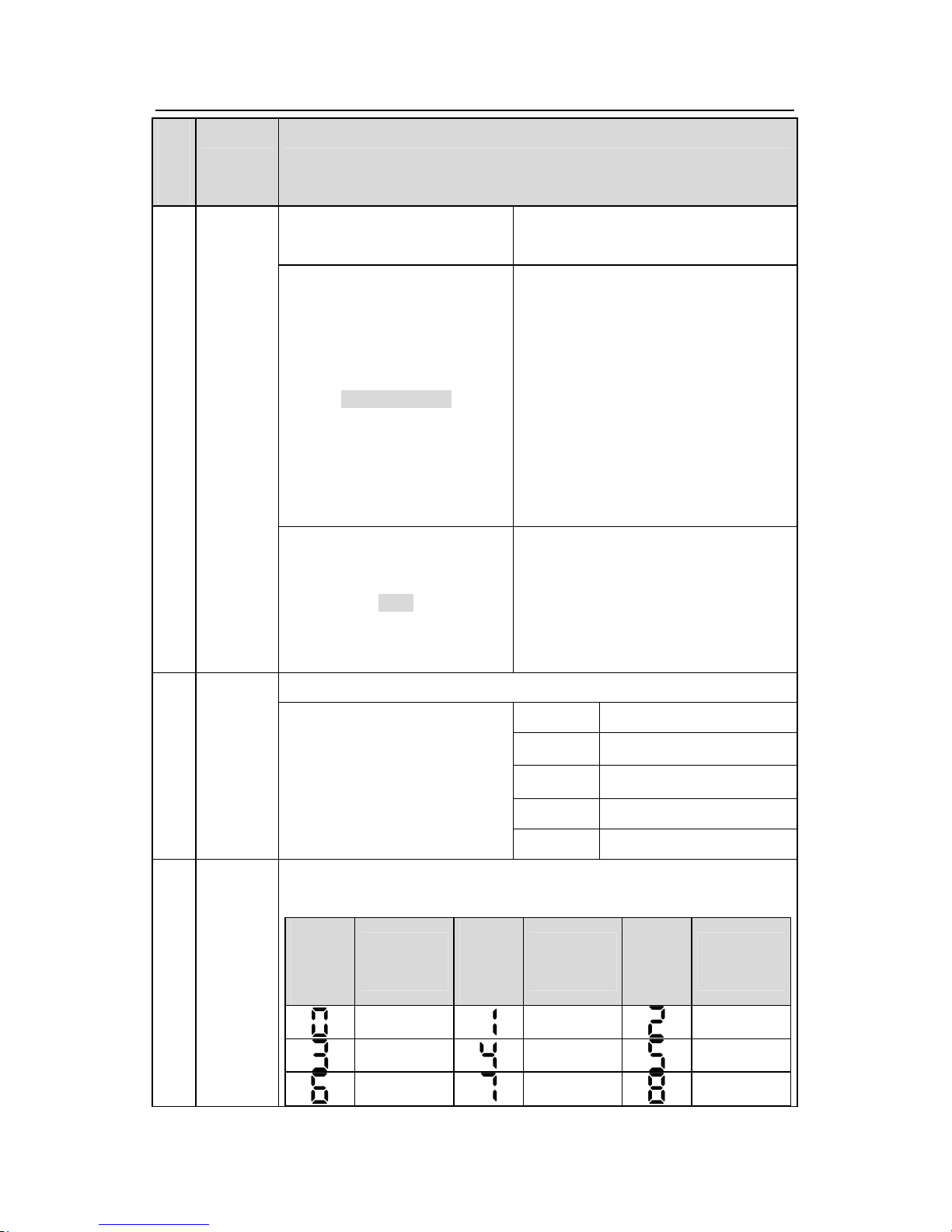
Goodrive300 inverters Keypad operation procedure
41
Seri
al
No.
Name
Description
the inverter is in the reverse rotation
state
LOCAL/REMOT
LED for keypad operation, terminals
operation and remote communication
control
LED off means that the inverter is in the
keypad operation state; LED blinking
means the inverter is in the terminals
operation state; LED on means the
inverter is in the remote communication
control state.
TRIP
LED for faults
LED on when the inverter is in the fault
state; LED off in normal state; LED
blinking means the inverter is in the
pre-alarm state.
Mean the unit displayed currently
Hz Frequency unit
A Current unit
V Voltage unit
RPM Rotating speed unit
2 Unit LED
% Percentage
3
Code
displaying
zone
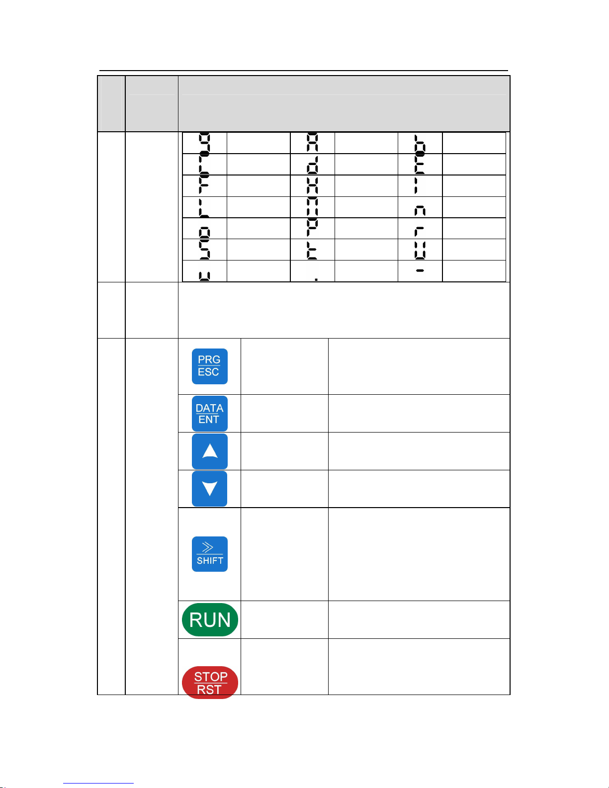
5-figure LED display displays various monitoring data and alarm code
such as set frequency and output frequency.
Display
ed
word
Correspon
ding word
Display
ed
word
Correspon
ding word
Display
ed
word
Correspon
ding word
0
1
2
3
4
5
6
7
8
Page 43
Goodrive300 inverters Keypad operation procedure
42
Seri
al
No.
Name
Description
9
A
B
C
d
E
F
H
I
L
N
n
o
P
r
S
t
U
v
.
-
4
Digital
potentiom
eter
Tuning frequency. Please refer to P08.41.
Programm
ing key
Enter or escape from the first level
menu and remove the parameter
quickly
Entry key
Enter the menu step-by-step
Confirm parameters
UP key
Increase data or function code
progressively
DOWN key
Decrease data or function code
progressively
Right-shift key
Move right to select the displaying
parameter circularly in stopping and
running mode.
Select the parameter modifying digit
during the parameter modification
Run key
This key is used to operate on the
inverter in key operation mode
5
Buttons
Stop/
Reset key
This key is used to stop in running state
and it is limited by function code P07.04
This key is used to reset all control
Page 44
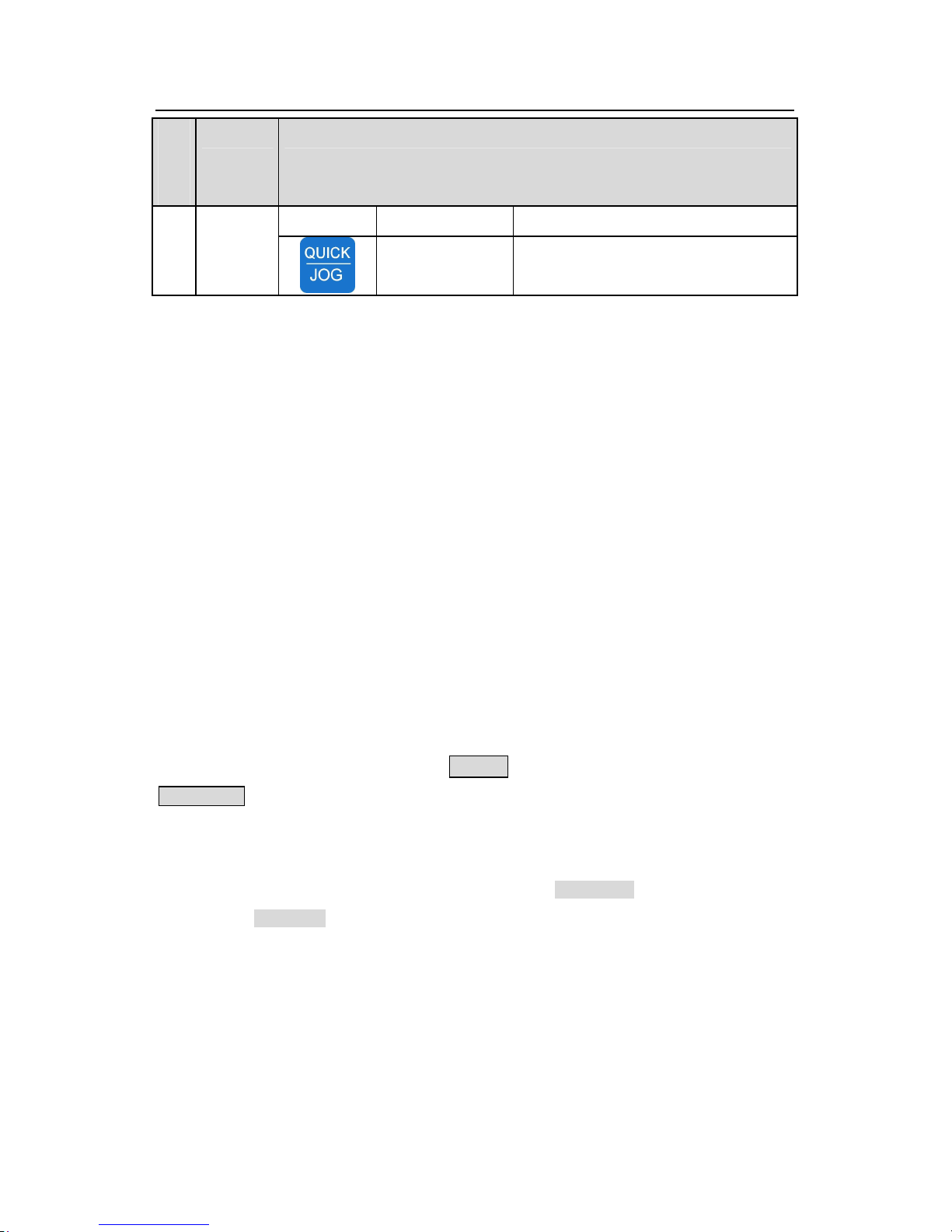
Goodrive300 inverters Keypad operation procedure
43
Seri
al
No.
Name
Description
modes in the fault alarm state
Quick key
The function of this key is confirmed by
function code P07.02.
5.3 Keypad displaying
The keypad displaying state of Goodrive300 series inverters is divided into stopping state
parameter, running state parameter, function code parameter editing state and fault alarm
state and so on.
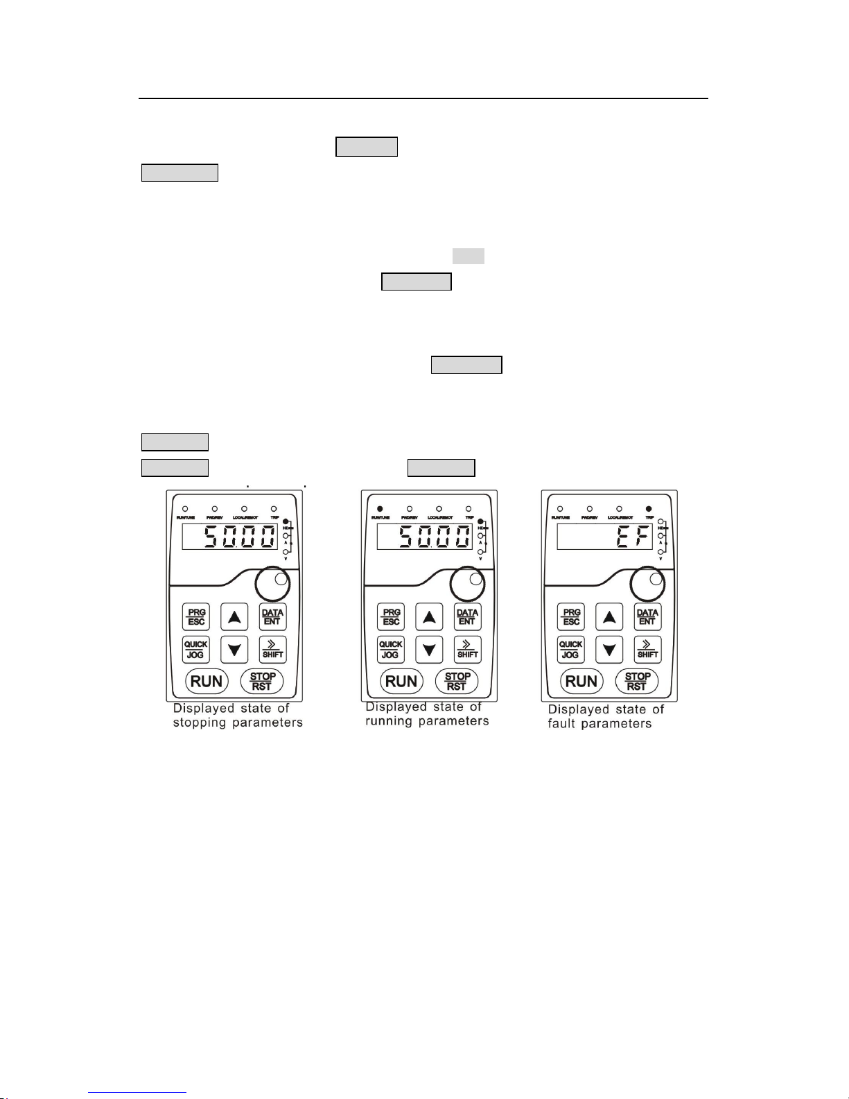
5.3.1 Displayed state of stopping parameter
When the inverter is in the stopping state, the keypad will display stopping parameters which
is shown in figure 5-2.
In the stopping state, various kinds of parameters can be displayed. Select the parameters
to be displayed or not by P07.07. See the instructions of P07.07 for the detailed definition of
each bit.
In the stopping state, there are 14 stopping parameters can be selected to be displayed or
not. They are: set frequency, bus voltage, input terminals state, output terminals state, PID
given value, PID feedback value, torque set value, AI1, AI2, AI3, HDI, PLC and the current
stage of multi-stage speeds, pulse counting value, length value. P07.07 can select the
parameter to be displayed or not by bit and》/SHIFT can shift the parameters form left to right,
QUICK/JOG(P07.02=2) can shift the parameters form right to left.
5.3.2 Displayed state of running parameters
After the inverter receives valid running commands, the inverter will enter into the running
state and the keypad will display the running parameters. RUN/TUNE LED on the keypad is
on, while the FWD/REV is determined by the current running direction which is shown as
figure 5-2.
In the running state, there are 24 parameters can be selected to be displayed or not. They
are: running frequency, set frequency, bus voltage, output voltage, output torque, PID given
value, PID feedback value, input terminals state, output terminals state, torque set value,
length value, PLC and the current stage of multi-stage speeds, pulse counting value, AI1,
AI2, AI3, HDI, percentage of motor overload, percentage of inverter overload, ramp given
Page 45
Goodrive300 inverters Keypad operation procedure
44
value, linear speed, AC input current. P07.05 and P07.06 can select the parameter to be
displayed or not by bit and 》 /SHIFT can shift the parameters form left to right,
QUICK/JOG(P07.02=2) can shift the parameters from right to left.
5.3.3 Displayed state of fault
If the inverter detects the fault signal, it will enter into the fault pre-alarm displaying state. The
keypad will display the fault code by flicking. The TRIP LED on the keypad is on, and the
fault reset can be operated by theSTOP/RST on the keypad, control terminals or
communication commands.
5.3.4 Displayed state of function codes editing
In the state of stopping, running or fault, press PRG/ESC to enter into the editing state (if
there is a password, see P07.00 ).The editing state is displayed on two classes of menu, and
the order is: function code group/function code number→function code parameter, press
DATA/ENT into the displayed state of function parameter. On this state, you can press
DATA/ENT to save the parameters or press PRG/ESC to retreat.
Fig 5-2 Displayed state
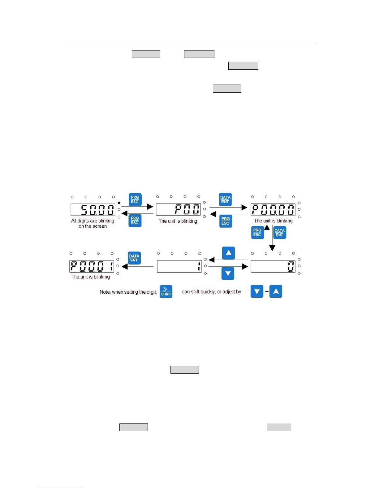
5.4 Keypad operation
Operate the inverter via operation panel. See the detailed structure description of function
codes in the brief diagram of function codes.
5.4.1 How to modify the function codes of the inverter
The inverter has three levels menu, which are:
1. Group number of function code (first-level menu)
2. Tab of function code (second-level menu)
3. Set value of function code (third-level menu)
Page 46
Goodrive300 inverters Keypad operation procedure
45
Remarks: Press both the PRG/ESC and the DATA/ENT can return to the second-level menu
from the third-level menu. The difference is: pressing DATA/ENT will save the set
parameters into the control panel, and then return to the second-level menu with shifting to
the next function code automatically; while pressing PRG/ESC will directly return to the
second-level menu without saving the parameters, and keep staying at the current function
code.
Under the third-level menu, if the parameter has no flickering bit, it means the function code
cannot be modified. The possible reasons could be:
1) This function code is not modifiable parameter, such as actual detected parameter,
operation records and so on;
2) This function code is not modifiable in running state, but modifiable in stop state.
Example:Set function code P00.01 from 0 to 1.
Fig 5-2 Sketch map of modifying parameters
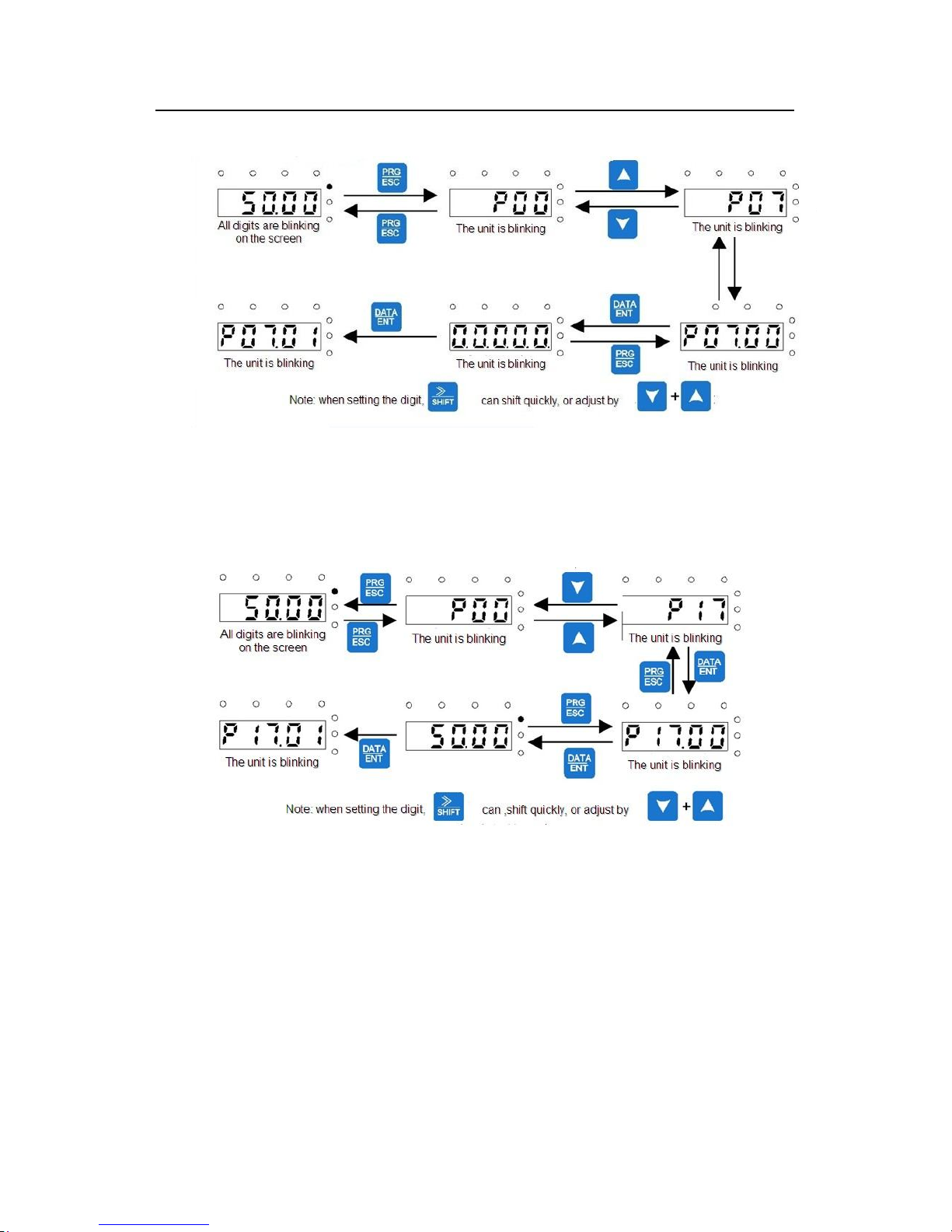
5.4.2 How to set the password of the inverter
Goodrive300 series inverters provide password protection function to users. Set P7.00 to
gain the password and the password protection becomes valid instantly after quitting from
the function code editing state. Press PRG/ESC again to the function code editing state,
“0.0.0.0.0” will be displayed. Unless using the correct password, the operators cannot enter
it.
Set P7.00 to 0 to cancel password protection function.
The password protection becomes effective instantly after retreating form the function code
editing state. Press PRG/ESC again to the function code editing state, “0.0.0.0.0” will be
Page 47
Goodrive300 inverters Keypad operation procedure
46
displayed. Unless using the correct password, the operators cannot enter it.
Fig 5-3 Sketch map of password setting
5.4.3 How to watch the inverter state through function codes
Goodrive300 series inverters provide group P17 as the state inspection group. Users can
enter into P17 directly to watch the state.
Fig 5-4 Sketch map of state watching
Page 48

Goodrive300 inverters Function codes
47
Function Parameters 6
6.1 What this chapter contains
This chapter lists and describes the function parameters.
6.2 Goodrive300 general series function parameters
The function parameters of Goodrive300 series inverters have been divided into 30 groups
(P00~P29) according to the function, of which P18~P28 are reserved. Each function group
contains certain function codes applying 3-level menus. For example, “P08.08” means the
eighth function code in the P8 group function, P29 group is factory reserved, and users are
forbidden to access these parameters.
For the convenience of function codes setting, the function group number corresponds to the
first level menu, the function code corresponds to the second level menu and the function
code corresponds to the third level menu.
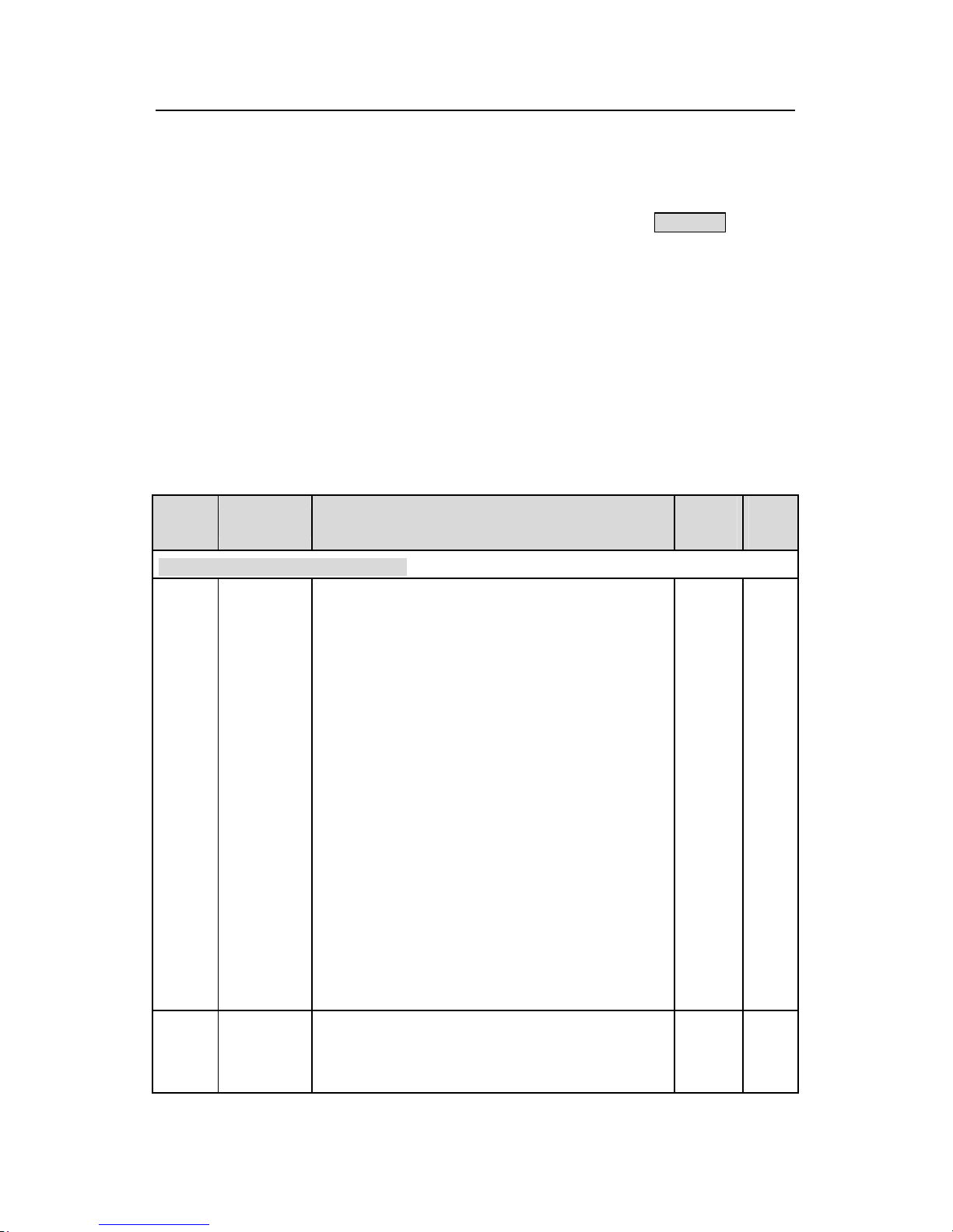
1. Below is the instruction of the function lists:
The first line “Function code”:codes of function parameter group and parameters;
The second line “Name”:full name of function parameters;
The third line “Detailed illustration of parameters”:Detailed illustration of the function
parameters
The fourth line “Default value”:the original factory set value of the function parameter;
The fifth line “Modify”:the modifying character of function codes (the parameters can be
modified or not and the modifying conditions),below is the instruction:
“○”: means the set value of the parameter can be modified on stop and running state;
“◎”: means the set value of the parameter can not be modified on the running state;
“●”: means the value of the parameter is the real detection value which can not be
modified.
(The inverter has limited the automatic inspection of the modifying character of the
parameters to help users avoid mismodifying)
2. “Parameter radix” is decimal (DEC), if the parameter is expressed by hex, then the
parameter is separated from each other when editing. The setting range of certain bits are
0~F (hex).
3.”The default value” means the function parameter will restore to the default value during
default parameters restoring. But the detected parameter or recorded value won’t be
Page 49
Goodrive300 inverters Function codes
48
restored.
4. For a better parameter protection, the inverter provides password protection to the
parameters. After setting the password (set P07.00 to any non-zero number), the system will
come into the state of password verification firstly after the user press PRG/ESC to come
into the function code editing state. And then “0.0.0.0.0.” will be displayed. Unless the user
input right password, they cannot enter into the system. For the factory setting parameter
zone, it needs correct factory password (remind that the users can not modify the factory
parameters by themselves, otherwise, if the parameter setting is incorrect, damage to the
inverter may occur). If the password protection is unlocked, the user can modify the
password freely and the inverter will work as the last setting one. When P07.00 is set to 0,
the password can be canceled. If P07.00 is not 0 during powering on, then the parameter is
protected by the password. When modify the parameters by serial communication, the
function of the password follows the above rules, too.
Functio
n code
Name Detailed instruction of parameters
Default
value
Modif
y
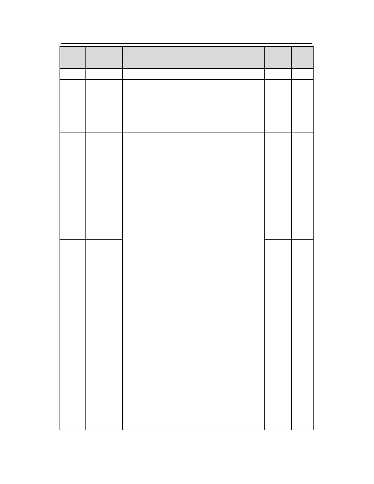
P00 Group Basic function group
P00.00
Speed
control mode
0: Sensorless vector control mode 0 (applying to
AM,SM)
0 is suitable in most cases, and in principle, one
inverter can only drive one motor in the vector
control mode.
1: Sensorless vector control mode 1 (applying to
AM)
1 is suitable in high performance cases with the
advantage of high accuracy of rotating speed and
torque. It does not need to install pulse encoder.
2:V/F control (applying to AM,SM)
2 is suitable in cases where it does not need high
control accuracy, such as the load of fan and pump.
One inverter can drive multiple motors.
Note: AM-Asynchronous motor SM- synchronous
motor
1 ◎
P00.01
Run
command
channel
Select the run command channel of the inverter.
The control command of the inverter includes:
start-up, stop, forward, reverse, jogging and fault
0 ○
Page 50
Goodrive300 inverters Function codes
49
Functio
n code
Name Detailed instruction of parameters
Default
value
Modif
y
reset.
0:Keypad running command
channel(“LOCAL/REMOT” light off)
Carry out the command control by RUN, STOP/RST
on the keypad.
Set the multi-function key QUICK/JOG to
FWD/REVC shifting function (P07.02=3) to change
the running direction; press RUN and STOP/RST
simultaneously in running state to make the inverter
coast to stop.
1:Terminal running command channel
(“LOCAL/REMOT” flickering)
Carry out the running command control by the
forward rotation, reverse rotation and forward
jogging and reverse jogging of the multi
-function
terminals
2:Communication running command channel
(“LOCAL/REMOT” on);
The running command is controlled by the upper
monitor via communication
P00.02
Communicati
on running
commands
channel
Select the controlling communication command
channel of the inverter.
0:MODBUS communication channel
1:PROFIBUS communication channel
2:Ethernet communication channel
3:CAN communication channel
Note: 1, 2 and 3 are extension functions which can
be used only when corresponding extension cards
are configured.
0 ○
P00.03
Max. output
frequency
This parameter is used to set the maximum output
frequency of the inverter. Users should pay attention
to this parameter because it is the foundation of the
frequency setting and the speed of acceleration and
deceleration.
50.00H
z
◎
Page 51
Goodrive300 inverters Function codes
50
Functio
n code
Name Detailed instruction of parameters
Default
value
Modif
y
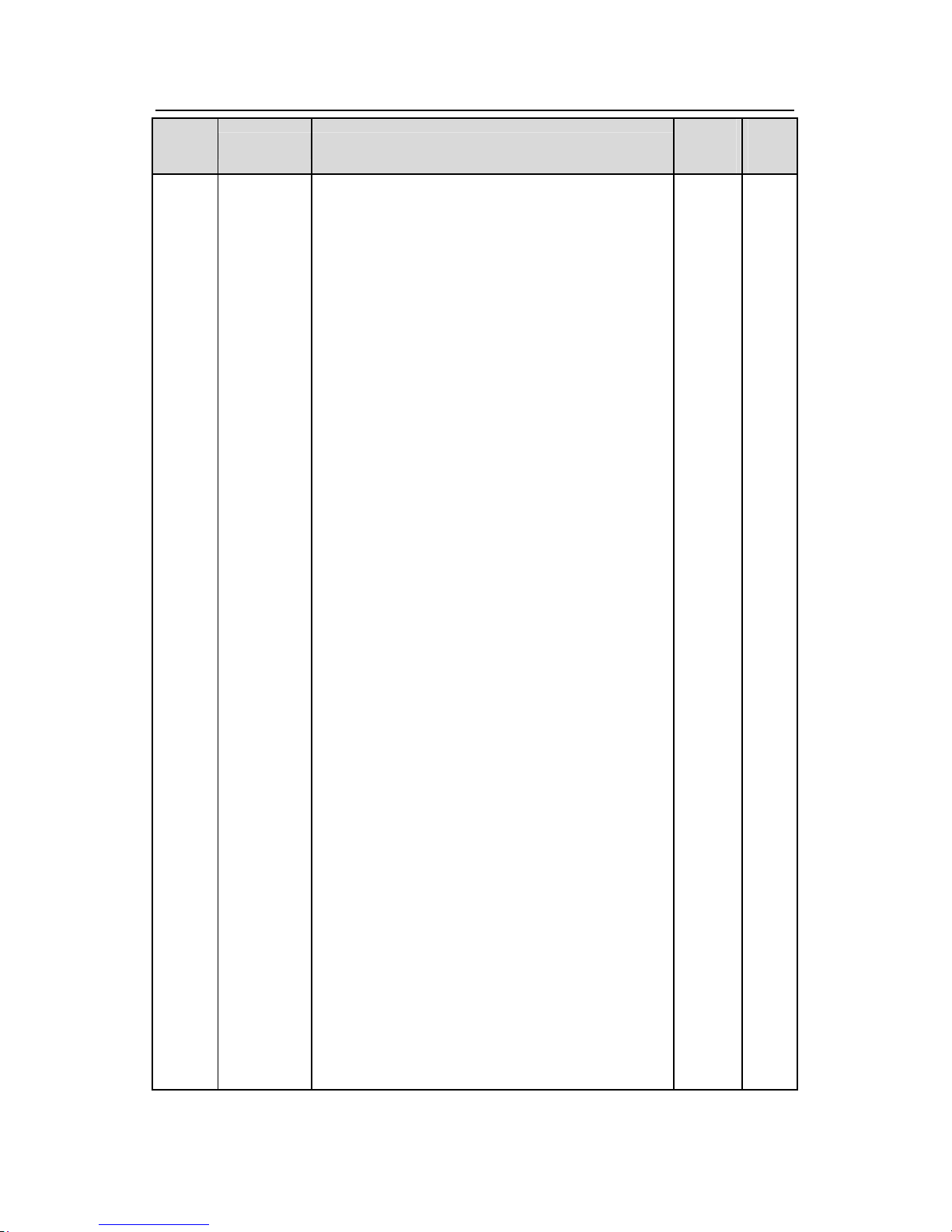
Setting range: P00.04~400.00Hz
P00.04
Upper limit of
the running
frequency
The upper limit of the running frequency is the upper
limit of the output frequency of the inverter which is
lower than or equal to the maximum frequency.
Setting range:P00.05~P00.03 (Max. output
frequency)
50.00H
z
◎
P00.05
Lower limit of
the running
frequency
The lower limit of the running frequency is that of the
output frequency of the inverter.
The inverter runs at the lower limit frequency if the
set frequency is lower than the lower limit one.
Note: Max. output frequency ≥ Upper limit frequency
≥ Lower limit frequency
Setting range:0.00Hz~P00.04 (Upper limit of the
running frequency)
0.00Hz ◎
P00.06
A frequency
command
0 ○
P00.07
B frequency
command
0:Keypad data setting
Modify the value of function code P00.10 (set the
frequency by keypad) to modify the frequency by the
keypad.
1:Analog AI1 setting
2:Analog AI2 setting
3:Analog AI3 setting
Set the frequency by analog input terminals.
Goodrive300 series inverters provide 3 ways analog
input terminals as the standard configuration, of
which AI1/AI2 are the voltage/current option
(0~10V/0~20mA) which can be shifted by jumpers;
while AI3 is voltage input (
-10V~+10V).
Note:
when analog AI1/AI2 select 0~20mA input, the
corresponding voltage of 20mA is 10V.
100.0% of the analog input setting corresponds to
the maximum frequency (function code P00.03) in
forward direction and -100.0% corresponds to the
maximum frequency in reverse direction (function
code P00.03)
1 ○
Page 52
Goodrive300 inverters Function codes
51
Functio
n code
Name Detailed instruction of parameters
Default
value
Modif
y
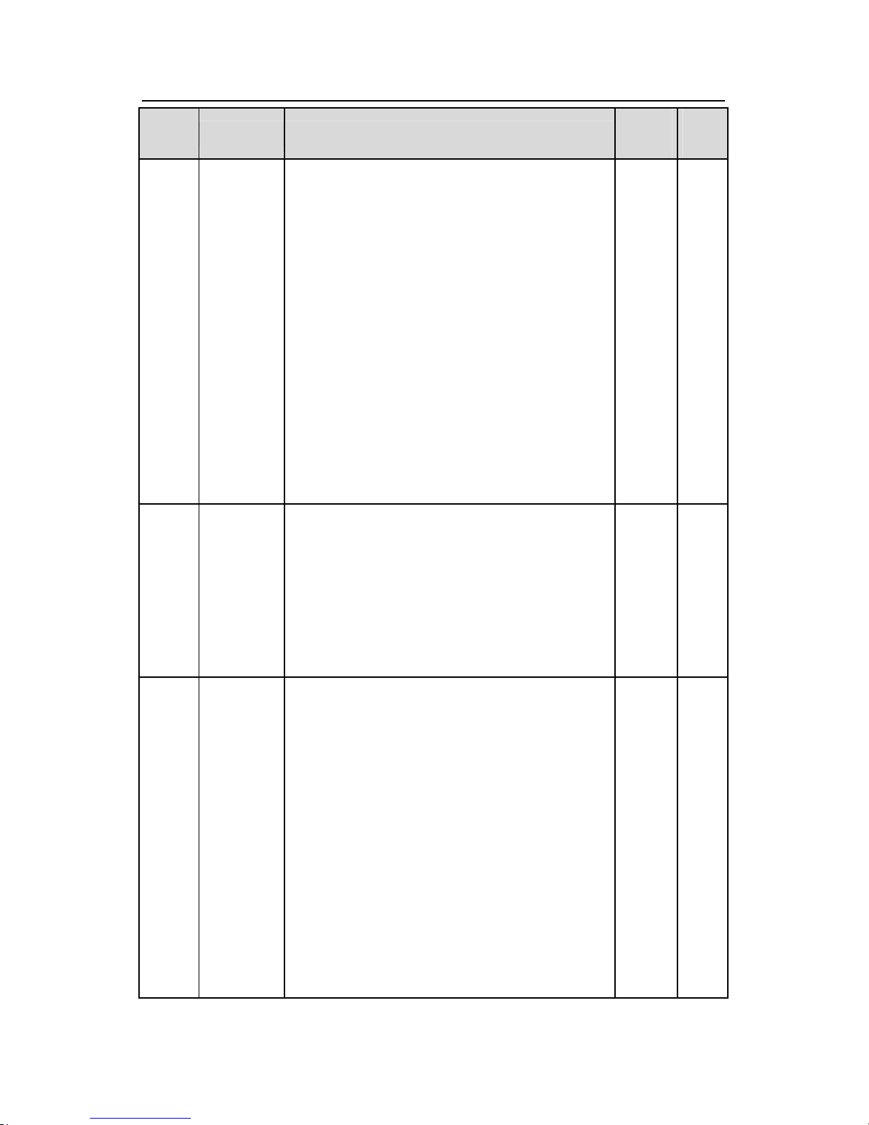
4:High-speed pulse HDI setting
The frequency is set by high-speed pulse terminals.
Goodrive300 series inverters provide 1 way high
speed pulse input as the standard configuration. The
pulse frequency range is 0.0~50.00kHz.
100.0% of the high speed pulse input setting
corresponds to the maximum frequency in forward
direction (function code P00.03) and -100.0%
corresponds to the maximum frequency in reverse
direction (function code P00.03).
Note: The pulse setting can only be input by
multi-function terminals HDI. Set P05.00 (HDI input
selection) to high speed pulse input, and set P05.49
(HDI high speed pulse input function selection) to
frequency setting input.
5:Simple PLC program setting
The inverter runs at simple PLC program mode
when P00.06=5 or P00.07=5. Set P10 (simple PLC
and multi-stage speed control) to select the running
frequency, running direction, ACC/DEC time and the
keeping time of corresponding stage. See the
function description of P10 for detailed information.
6: Multi-stage speed running setting
The inverter runs at multi-stage speed mode when
P00.06=6 or P00.07=6. Set P05 to select the current
running stage, and set P10 to select the current
running frequency.
The multi-stage speed has the priority when P00.06
or P00.07 does not equal to 6, but the setting stage
can only be the 1~15 stage. The setting stage is
1~15 if P00.06 or P00.07 equals to 6.
7: PID control setting
The running mode of the inverter is process PID
control when P00.06=7 or P00.07=7. It is necessary
Page 53
Goodrive300 inverters Function codes
52
Functio
n code
Name Detailed instruction of parameters
Default
value
Modif
y
to set P09. The running frequency of the inverter is
the value after PID effect. See P09 for the detailed
information of the given source, given value,
feedback source of PID.
8:MODBUS communication setting
The frequency is set by MODBUS communication.
See P14 for detailed information.
9:PROFIBUS communication setting
The frequency is set by PROFIBUS communication.
See P15 for the detailed information.
10:Ethernet communication setting(reserved)
11:CAN communication setting(reserved)
Note:A frequency and B frequency can not set as
the same frequency given method.
P00.08
B frequency
command
reference
0:Maximum output frequency, 100% of
B frequency setting corresponds to the maximum
output frequency
1:A frequency command, 100% of B frequency
setting corresponds to the maximum output
frequency. Select this setting if it needs to adjust on
the base of A frequency command.
0 ○
P00.09
Combination
of the setting
source
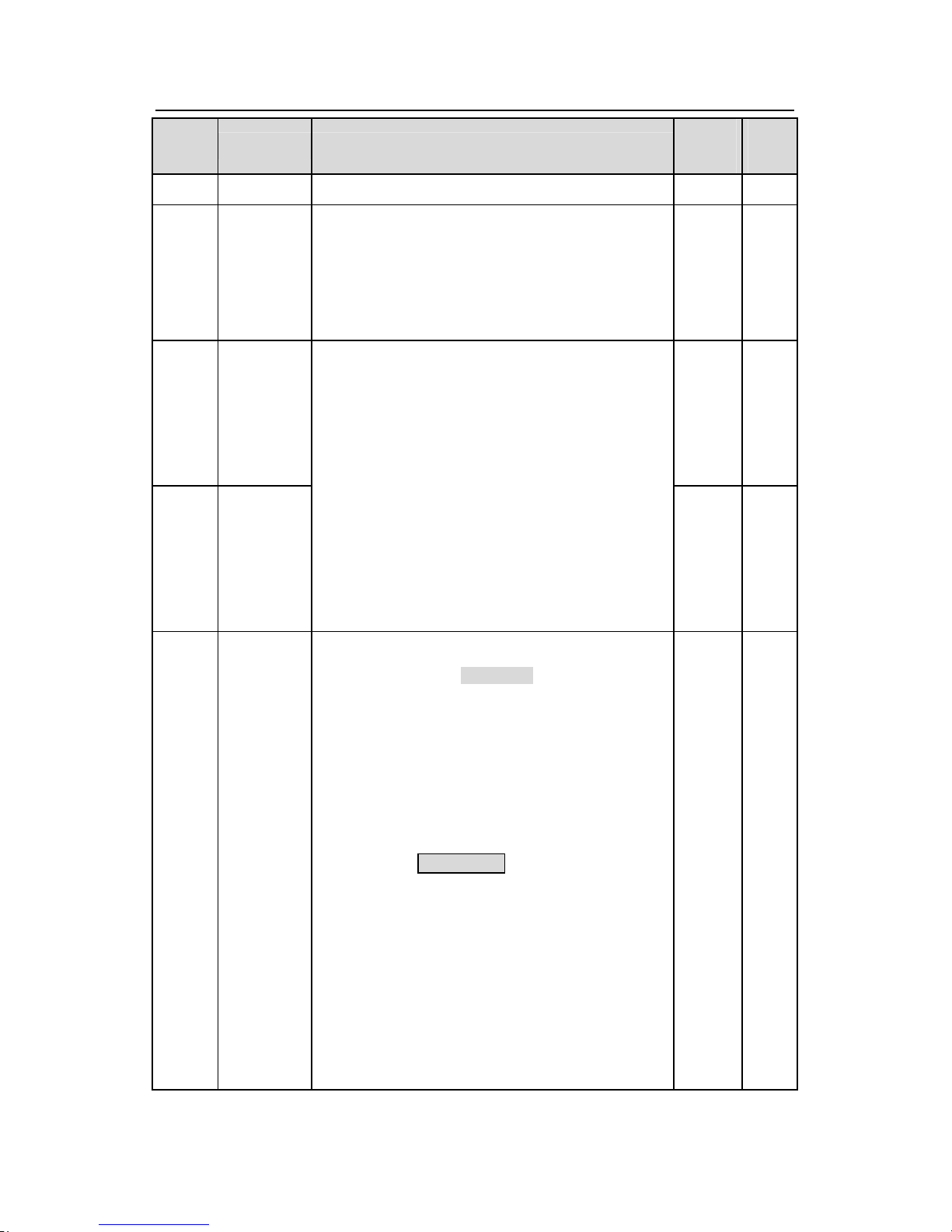
0: A, the current frequency setting is A freauency
command
1: B, the current frequency setting is B frequency
command
2: A+B, the current frequency setting is A frequency
command + B frequency command
3: A-B, the current frequency setting is A frequency
command - B frequency command
4: Max (A, B):The bigger one between A frequency
command and B frequency is the set frequency.
5: Min (A, B):The lower one between A frequency
command and B frequency is the set frequency.
Note:The combination manner can be shifted by
0 ○
Page 54
Goodrive300 inverters Function codes
53
Functio
n code
Name Detailed instruction of parameters
Default
value
Modif
y
P5(terminal function)
P00.10
Keypad set
frequency
When A and B frequency commands are selected as
“keypad setting”, the value of the function code is the
original setting one of the frequency data of the
inverter.
Setting range:0.00 Hz~P00.03(the Max. frequency)
50.00H
z
○
P00.11 ACC time 1
Depend
on
model
○
P00.12 DEC time 1
ACC time means the time needed if the inverter
speeds up from 0Hz to the Max. One (P00.03).
DEC time means the time needed if the inverter
speeds down from the Max. Output frequency to 0Hz
(P00.03).
Goodrive300 series inverters define four groups of
ACC/DEC time which can be selected by P05. The
factory default ACC/DEC time of the inverter is the
first group.
Setting range of P00.11 and P00.12:0.0~3600.0s
Depend
on
model
○
P00.13
Running
direction
0: Runs at the default direction, the inverter runs in
the forward direction. FWD/REV indicator is off.
1:Runs at the oppositing direction, the inverter runs
in the reverse direction. FWD/REV indicator is on.
Modify the function code to shift the rotation direction
of the motor. This effect equals to the shifting the
rotation direction by adjusting either two of the motor
lines (U, V and W). The motor rotation direction can
be changed by QUICK/JOG
on the keypad. Refer to
parameter P07.02.
Note: When the function parameter comes back to
the default value, the motor’s running direction will
come back to the factory default state, too. In some
cases it should be used with caution after
commissioning if the change of rotation direction is
disabled.
2: Forbid to run in reverse direction: It can be used in
0 ○
Page 55
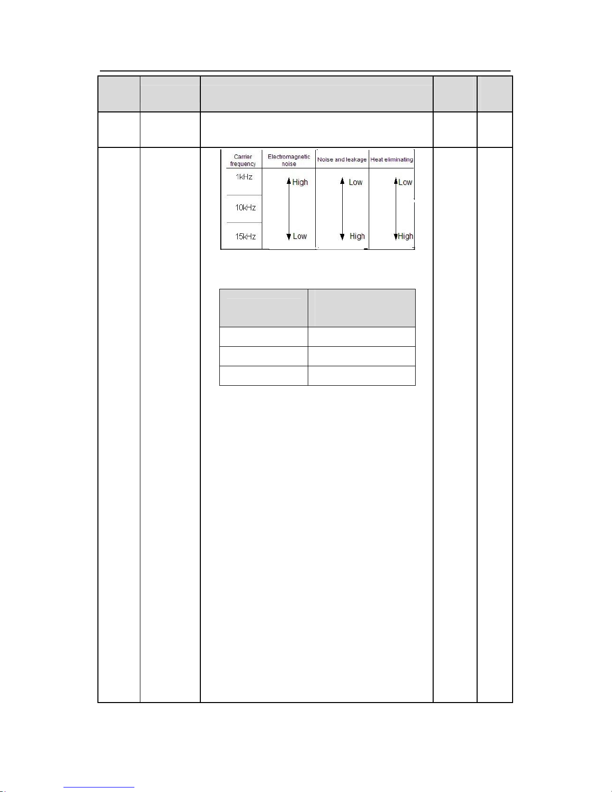
Goodrive300 inverters Function codes
54
Functio
n code
Name Detailed instruction of parameters
Default
value
Modif
y
some special cases if the reverse running is
disabled.
P00.14
Carrier
frequency
setting
The relationship table of the motor type and carrier
frequency:
Motor type
The factory value of
carrier frequency
1.5~11kW 8kHz
15~55kW 4kHz
Above 75kW
2kHz
The advantage of high carrier frequency: ideal
current waveform, little current harmonic wave and
motor noise.
The disadvantage of high carrier frequency:
increasing the switch loss, increasing inverter
temperature and the impact to the output capacity.
The inverter needs to derate on high carrier
frequency. At the same time, the leakage and
electrical magnetic interference will increase.
Applying low carrier frequency is contrary to the
above, too low carrier frequency will cause unstable
running, torque decreasing and surge.
The manufacturer has set a reasonal carrier
frequency when the inverter is in factory. In general,
users do not need to change the parameter.
When the frequency used exceeds the default carrier
frequency, the inverter needs to derate 20% for each
Depend
on
model
○
Page 56
Goodrive300 inverters Function codes
55
Functio
n code
Name Detailed instruction of parameters
Default
value
Modif
y
additional 1k carrier frequency.
Setting range:1.0~15.0kHz
P00.15
Motor
parameter
autotuning
0:No operation
1:Rotation autotuning
Comprehensive motor parameter autotune
It is recommended to use rotation autotuning when
high control accuracy is needed.
2: Static autotuning 1(autotune totally); It is suitable
in the cases when the motor can not de-couple form
the load. The antotuning
for the motor parameter will
impact the control accuracy.
3: Static autotuning 2(autotune part parameters);
when the current motor is motor 1, autotune
P02.06
,
P02.07, P02.08; and when the current motor is
motor 2, autotune P12.06, P12.07, P02.08.
0 ◎
P00.16
AVR function
selection
0:Invalid
1:Valid during the whole prodecure
The auto-adjusting function of the inverter can
cancel the impact on the output voltage of the
inverter because of the bus voltage fluctuation.
1 ○
P00.17 Reserved Reserved 0 ◎
P00.18
Function
restore
parameter
0:No operation
1:Restore the default value
2:Cancel the fault record
Note: The function code will restore to 0 after
finishing the operation of the selected function code.
Restoring to the default value will cancel the user
password, please use this function with caution.
0 ◎
P01 Group Start-up and stop control
P01.00 Start mode
0:Start-up directly:start from the starting frequency
P01.01
1:Start-up after DC braking: start the motor from the
starting frequency after DC braking (set the
parameter P01.03 and P01.04). It is suitable in the
0 ◎
Page 57
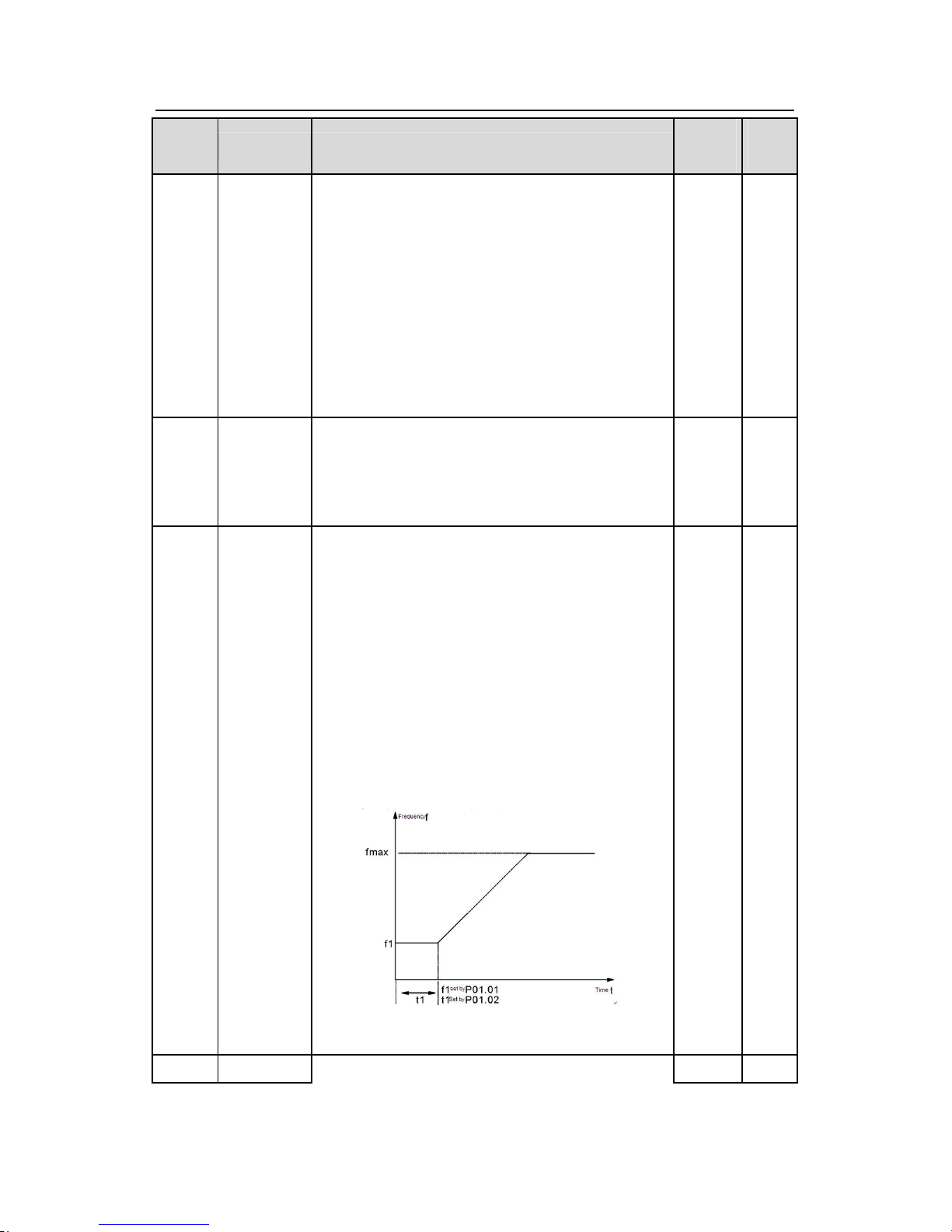
Goodrive300 inverters Function codes
56
Functio
n code
Name Detailed instruction of parameters
Default
value
Modif
y
cases where reverse rotation may occur to the low
inertia load during starting.
2: Start-up after reverse tracing: start the rotating
motor smoothly after tracking the rotation speed and
direction automatically. It is suitable in the cases
where reverse rotation
may occur to the big inertia
load during starting.
Note: it is recommended to start the synchronous
motor directly.
P01.01
Starting
frequency of
direct start
Starting frequency of direct start-up means the
original frequency during the inverter starting. See
P01.02 for detailed information.
Setting range: 0.00~50.00Hz
0.50Hz ◎
P01.02
Retention
time of the
starting
frequency
Set a proper starting frequency to increase the
torque of the inverter during starting. During the
retention time of the starting frequency, the output
frequency of the inverter is the starting frequency.
And then, the inverter will run from the starting
frequency to the set frequency. If the set frequency is
lower than the starting frequency, the inverter will
stop running and keep in the stand-by state. The
starting frequency is not limited in the lower limit
frequency.
Setting range: 0.0~50.0s
0.0s ◎
P01.03 The braking
The inverter will carry out DC braking at the braking
0.0%
◎
Page 58
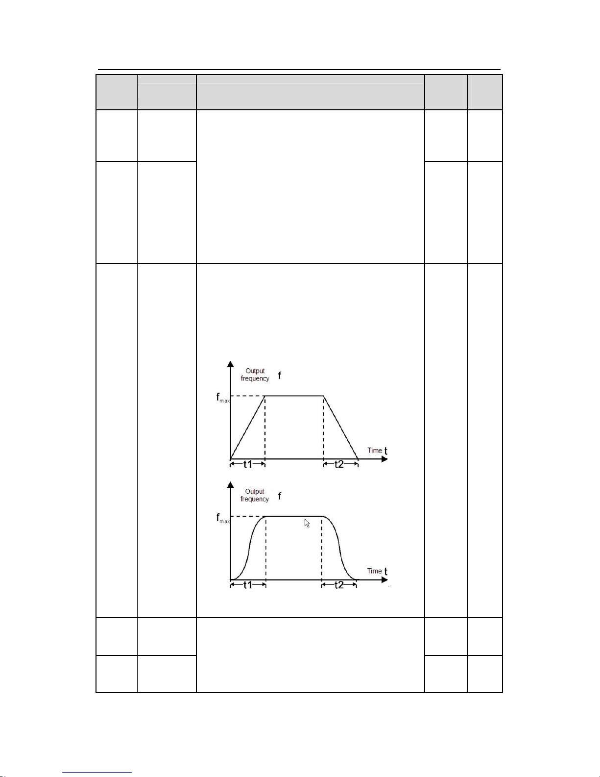
Goodrive300 inverters Function codes
57
Functio
n code
Name Detailed instruction of parameters
Default
value
Modif
y
current
before
starting
P01.04
The braking
time before
starting
current set before starting and it will speed up after
the DC braking time. If the DC braking time is set to
0, the DC braking is invalid.
The stronger the braking current, the bigger the
braking power. The DC braking current before
starting means the percentage of the rated
current of
the inverter.
The setting range of P01.03: 0.0~150.0%
The setting range of P01.04: 0.0~50.0s
0.0s ◎
P01.05
ACC/DEC
selection
The changing mode of the frequency during start-up
and running.
0:Linear type
The output frequency increases or decreases
linearly.
1: Reserved
0 ◎
P01.06
Reserved
Reserv
ed
◎
P01.07
Reserved
Reserv
ed
◎
Page 59
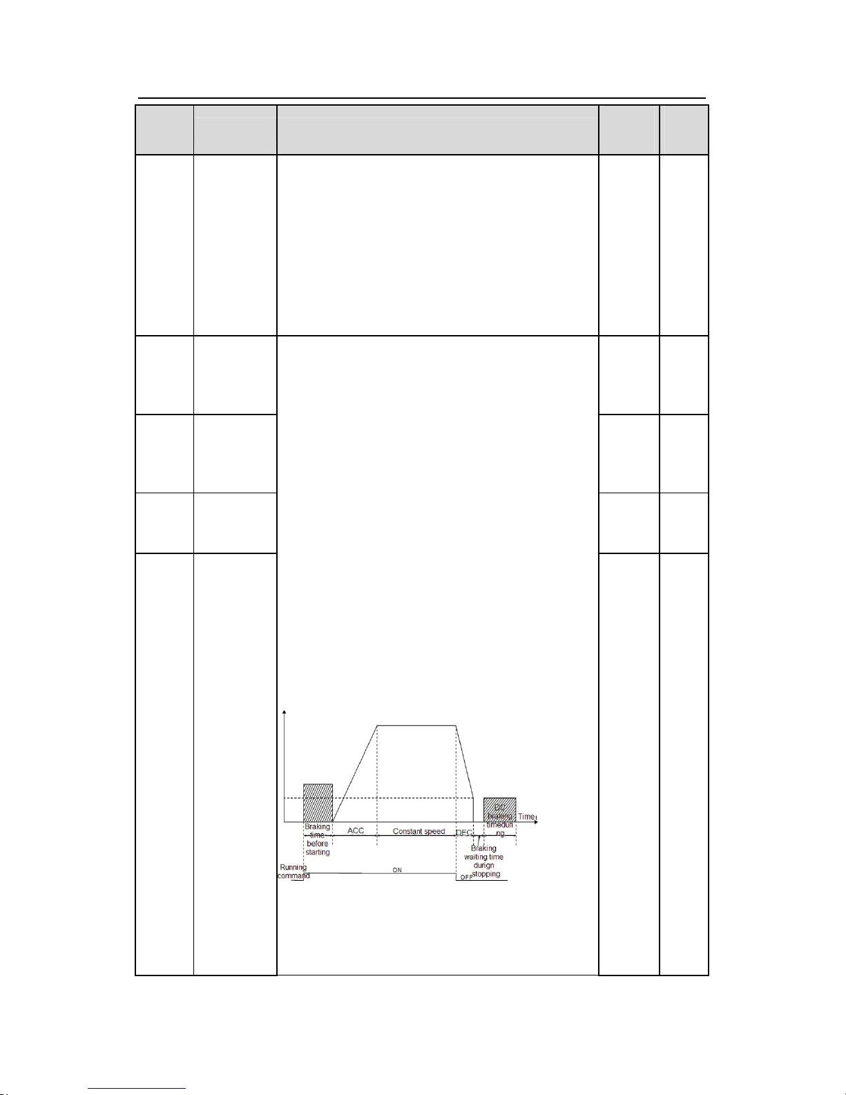
Goodrive300 inverters Function codes
58
Functio
n code
Name Detailed instruction of parameters
Default
value
Modif
y
P01.08 Stop mode
0: Decelerate to stop: after the stop command
becomes valid, the inverter decelerates to decrease
the output frequency during the set time. When the
frequency decreases to 0, the inverter stops.
1: Coast to stop: after the stop command becomes
valid, the inverter ceases the output immediately.
And the load coasts to stop at the mechanical inertia.
0 ○
P01.09
Starting
frequency of
DC braking
0.00Hz ○
P01.10
Waiting time
before DC
braking
0.0s ○
P01.11
DC braking
current
0.0%
○
P01.12
DC braking
time
The starting frequency of stop braking: the inverter
will carry on stop DC braking wh
en the frequency is
arrived during the procedure of decelerating to stop.
The waiting time of stop braking: before the stop DC
braking, the inverter will close output and begin to
carry on the DC braking after the waiting time. This
action is used to avoid the overcurrent fault caused
by DC braking when the speed is too high.
Stop DC braking current: the DC brake added. The
stronger the current, the bigger the DC braking
effect.
The braking time of stop braking:The retention time
of DC brake. If the time is 0, the DC brake is invalid.
The inverter will stop at the set deceleration time.
Setting range of P01.09: 0.00~P00.03 (the Max.
frequency)
Setting range of P01.10: 0.0~50.0s
0.0s
○
Page 60
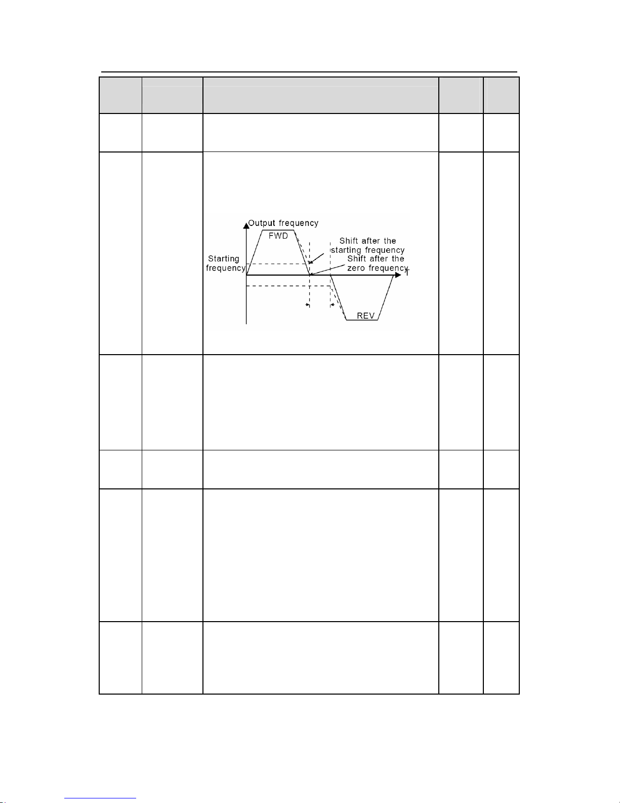
Goodrive300 inverters Function codes
59
Functio
n code
Name Detailed instruction of parameters
Default
value
Modif
y
Setting range of P01.11: 0.0~150.0%
Setting range of P01.12: 0.0~50.0s
P01.13
Dead time of
FWD/REV
rotation
During the procedure of switching for/rev rotation,
set the threshold by P01.14, which is as the table
below:
Setting range: 0.0~3600.0s
0.0s ○
P01.14
Shifting
between
FWD/REV
rotation
Set the threshold point of the inverter:
0:Switch after 0 frequency
1:Switch after the starting frequency
2: Switch after the speed reach P01.15 and delay for
P01.24
0 ◎
P01.15
Stopping
speed
0.00~100.00Hz 0.50 Hz ◎
P01.16
Detection of
stopping
speed
0: Speed setting (the only detection method in V/F
mode)
1: Speed detecting value
When the actual output frequency of the inverter is
lower than P01.15 and the lasting time is beyond
P01.17, the running state ends and the inverter
stops.
0 ◎
P01.17
Detection
time of the
feedback
If set P01.16 to 1, the feedback frequency is less
than or equal to P01.15 and detect in the set time of
P01.17, the inverter will stop; otherwise the inverter
0.05s
◎
Page 61
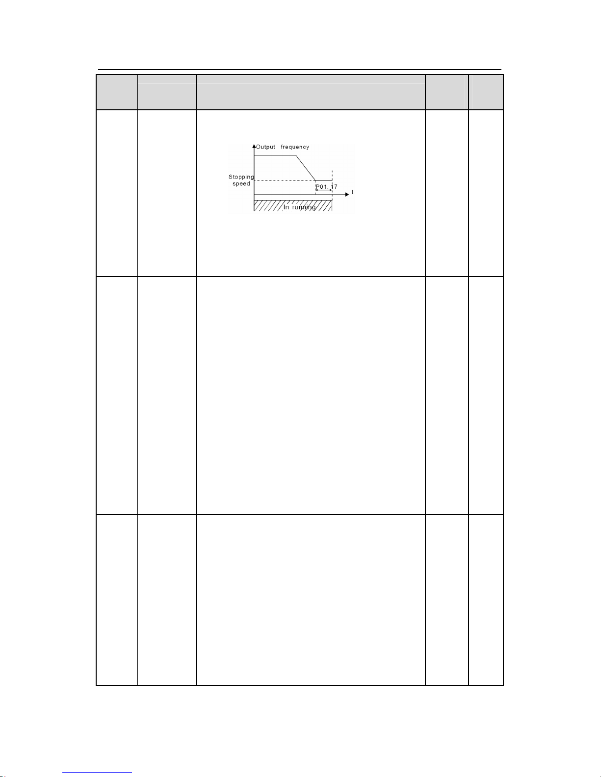
Goodrive300 inverters Function codes
60
Functio
n code
Name Detailed instruction of parameters
Default
value
Modif
y
speed
will stop after the set time of
P01.17.
Setting range:0.0~100.0s (only valid when
P01.16=1)
P01.18
Terminal
running
protection
when
powering on
When the running command channel is the terminal
control, the system will detect the state of the
running terminal during powering on.
0:The terminal running command is invalid when
powering on. Even the running
command is detected
to be valid during powering on, the inverter won’
t run
and the system keeps in the protection stat
e until the
running command is canceled and enabled again.
1: The terminal running command is valid when
powering on. If the running command is detected to
be valid during powering on, the system will start the
inverter automatically after the initialization.
Note:
this function should be selected with cautions,
or serious result may follow.
0 ○
P01.19
The running
frequency is
lower than
the lower
limit one
(valid if the
lower limit
frequency is
above 0)
This function code determines the running state of
the inverter when the set frequency is lower than the
lower-limit one.
0: Run at the lower-limit frequency
1: Stop
2: Hibernation
The inverter will coast to stop when the set
frequency is lower than the lower-limit one.if the set
frequency is above the lower limit one again and it
lasts for the time set by P01.20, the inverter will
0 ◎
Page 62
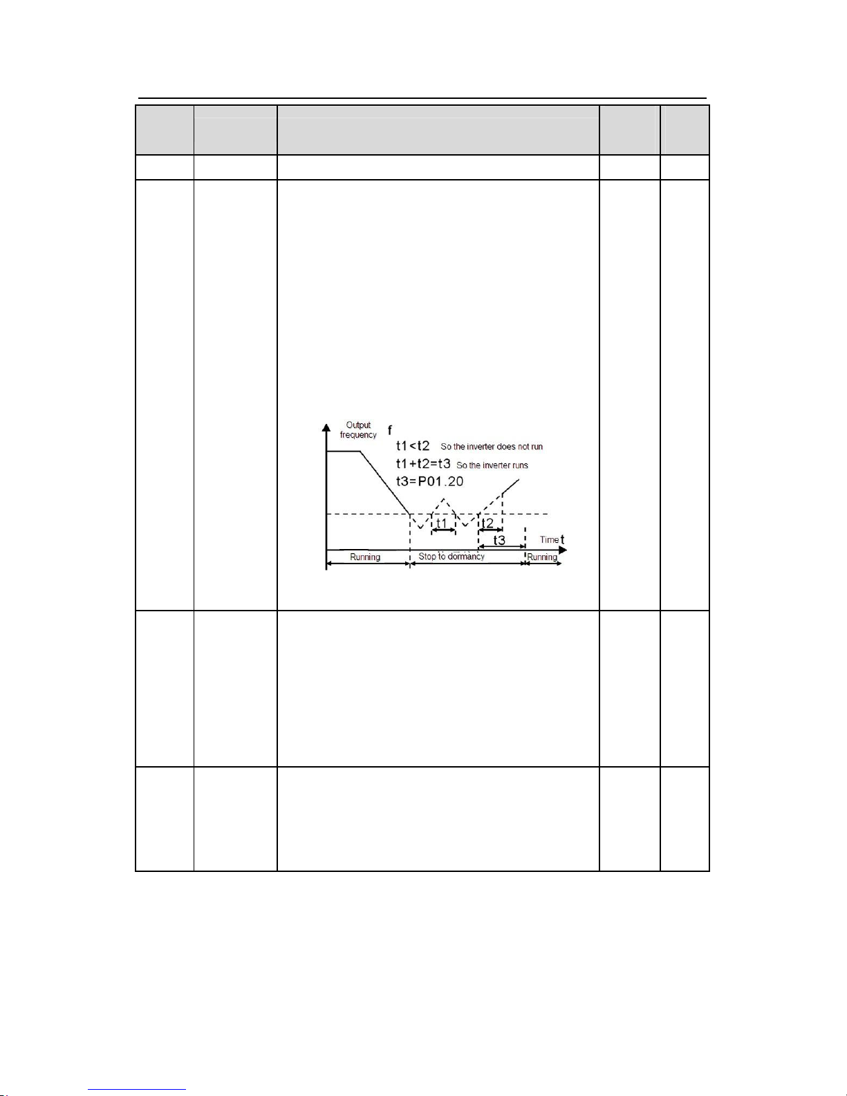
Goodrive300 inverters Function codes
61
Functio
n code
Name Detailed instruction of parameters
Default
value
Modif
y
come back to the running state automatically.
P01.20
Hibernation
restore delay
time
T
his function code determines the Hibernation delay
time. When the running frequency of the inverter is
lower than the lower limit one, the inverter will pause
to stand by.
When the set frequency is above the lower limit one
again and it lasts for the time set by P01.20, the
inverter will run automatically.
Note: The time is the total value when the set
frequency is above the lower limit one.
Setting range: 0.0~3600.0s (valid when P01.19=2)
0.0s ○
P01.21
Restart
after
power off
This function can enable the inverter start or not after
the power off and then power on.
0: Ddisable
1: Enable
, if the starting need is met, the inverter will
run automatically after waiting for the time defined by
P01.22.
0 ○
P01.22
The waiting
time of
restart after
power off
The function determines the waiting time before the
automatic running of the inverter when powering off
and then powering on.
1.0s ○
Page 63
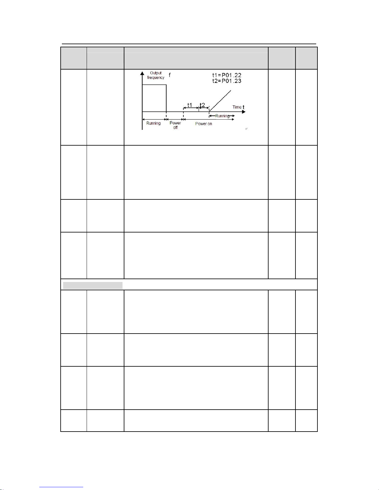
Goodrive300 inverters Function codes
62
Functio
n code
Name Detailed instruction of parameters
Default
value
Modif
y
Setting range: 0.0~3600.0s (valid when P01.21=1)
P01.23
Start delay
time
The function determines the brake release after the
running command is given, and the inverter is in a
stand-by state and wait for the delay time set by
P01.23
Setting range: 0.0~60.0s
0.0s ○
P01.24
Delay time of
the stop
speed
Setting range: 0.0~100.0 s 0.0s ●
P01.25
0Hz output
selection
Select the output mode at 0Hz.
0: Output without voltage
1: Output with voltage
2: Output at DC braking current at stopping
0 ●
P02 Group Motor 1
P02.00 Motor type 1
0:Asynchronous motor
1:Synchronous motor
Note: Switch the current motor by the switching
channel of P08.31.
0 ◎
P02.01
Asynchronou
s motor 1
rated power
0.1~3000.0kW
Depend
on
model
◎
P02.02
Asynchronou
s motor 1
rated
frequency
0.01Hz~P00.03(the Max. frequency)
50.00H
z
◎
P02.03
Asynchronou
s motor 1
1~36000rpm
Depend
on
◎
Page 64
Goodrive300 inverters Function codes
63
Functio
n code
Name Detailed instruction of parameters
Default
value
Modif
y
rated speed
model
P02.04
Asynchronou
s motor 1
rated voltage
0~1200V
Depend
on
model
◎
P02.05
Asynchronou
s motor 1
rated
current
0.8~6000.0A
Depend
on
model
◎
P02.06
Asynchronou
s motor 1
stator
resistor
0.001~65.535Ω
Depend
on
model
○
P02.07
Asynchronou
s motor 1
rotor resistor
0.001~65.535Ω
Depend
on
model
○
P02.08
Asynchronou
s motor 1
leakage
inductance
0.1~6553.5mH
Depend
on
model
○
P02.09
Asynchronou
s motor 1
mutual
inductance
0.1~6553.5mH
Depend
on
model
○
P02.10
Asynchronou
s motor 1
non-load
current
0.1~6553.5A
Depend
on
model
○
P02.11
Magnetic
saturation
coefficient 1
for the iron
core of AM1
0.0~100.0% 80.0%
◎
P02.12
Magnetic
saturation
0.0~100.0% 68.0%
◎
Page 65
Goodrive300 inverters Function codes
64
Functio
n code
Name Detailed instruction of parameters
Default
value
Modif
y
coefficient 2
for the iron
core of AM1
P02.13
Magnetic
saturation
coefficient 3
for the iron
core of AM1
0.0~100.0% 57.0%
◎
P02.14
Magnetic
saturation
coefficient 4
for the iron
core of AM1
0.0~100.0% 40.0%
◎
P02.15
Synchronous
motor 1 rated
power
0.1~3000.0kW
Depend
on
model
◎
P02.16
Synchronous
motor 1 rated
frequency
0.01Hz~P00.03(the Max. frequency)
50.00H
z
◎
P02.17
Synchronous
motor 1
number of
poles pairs
1~50 2 ◎
P02.18
Synchronous
motor 1 rated
voltage
0~1200V
Depend
on
model
◎
P02.19
Synchronous
motor 1 rated
current
0.8~6000.0A
Depend
on
model
◎
P02.20
Synchronous
motor 1
stator
resistor
0.001~65.535Ω
Depend
on
model
○
Page 66
Goodrive300 inverters Function codes
65
Functio
n code
Name Detailed instruction of parameters
Default
value
Modif
y
P02.21
Synchronous
motor 1
Direct axis
inductance
0.1~6553.5mH
Depend
on
model
○
P02.22
Synchronous
motor 1
Quadrature
axis
inductance
0.1~655.35mH
Depend
on
model
○
P02.23
Synchron
ous
motor 1
Back
EMF
constant
When P00.15=2, the set value of P02.23 cannot be
updated by autotuning, please count according to
the following method.
The counter-electromotive force constant can be
counted according to the parameters on the name
plate of the motor. There are three ways to count:
1. If the name plate designate the
counter-electromotive force constant Ke, then:
E=(Ke*nN*2π)/ 60
2. If the name plate designate the
counter-electromotive force constant
E’(V/1000r/min), then:
E=E’*nN/1000
3. If the name plate does not designate the above
parameters, then:
E=P/√3*I
In the above formulas: nN is the rated
rotation speed,
P is the rated power and I is the rated current.
Setting range: 0~10000
300 ○
P02.24 Reserved
●
P02.25 Reserved
●
P02.26
Motor 1
overload
protection
0:No protection
1: Common motor (with low speed compensation).
Because the heat-releasing effect of the common
motors will be weakened, the corresponding electric
2 ◎
Page 67
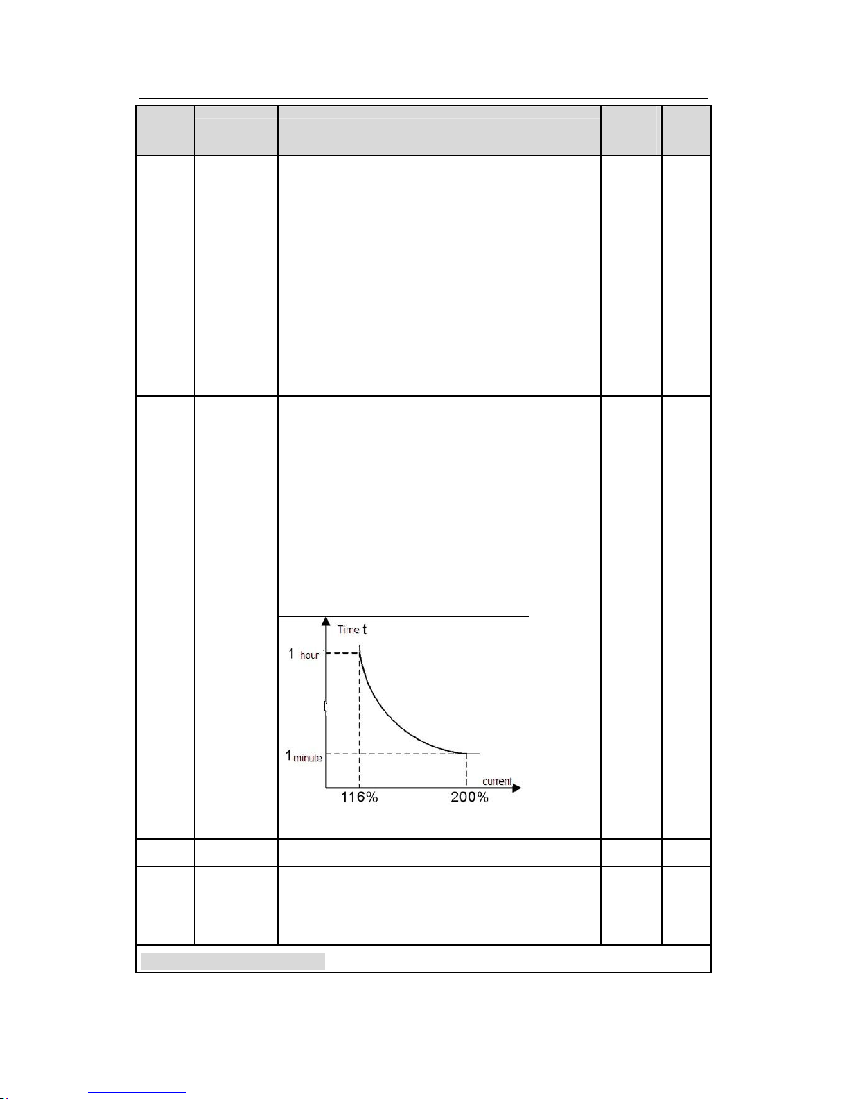
Goodrive300 inverters Function codes
66
Functio
n code
Name Detailed instruction of parameters
Default
value
Modif
y
heat protection will be adjusted properly. The low
speed compensation characteristic mentioned here
means reducing the threshold of the overload
protection of the motor whose running frequency is
below 30Hz.
2: Frequency conversion motor (without low speed
compensation) Because the heat-releasing effect of
the specific motors won’t be impacted by the rotation
speed, it is not necessary to adjust the protection
value during low-speed running.
P02.27
Motor 1 over
load
protection
coefficient
When P02.27=overload protection current of the
motor/rated current of the motor
S
o, the bigger the overload coefficient is, the shorter
the reporting time of the overload fault is. When the
overload coefficient <110%, there is no overload
protection. When the overload coefficient =116%,
the fault will be reported after 1 hour, when the
overload coefficient=200%, the fault will be reported
after 1 minute.
Setting range: 20.0%~120.0%
100.0% ○
P02.28 Reserved
●
P02.29
Parameter
display of
motor 1
0: Display according to the motor type
1: Display all
0 ●
P03 Group Vector control
Page 68
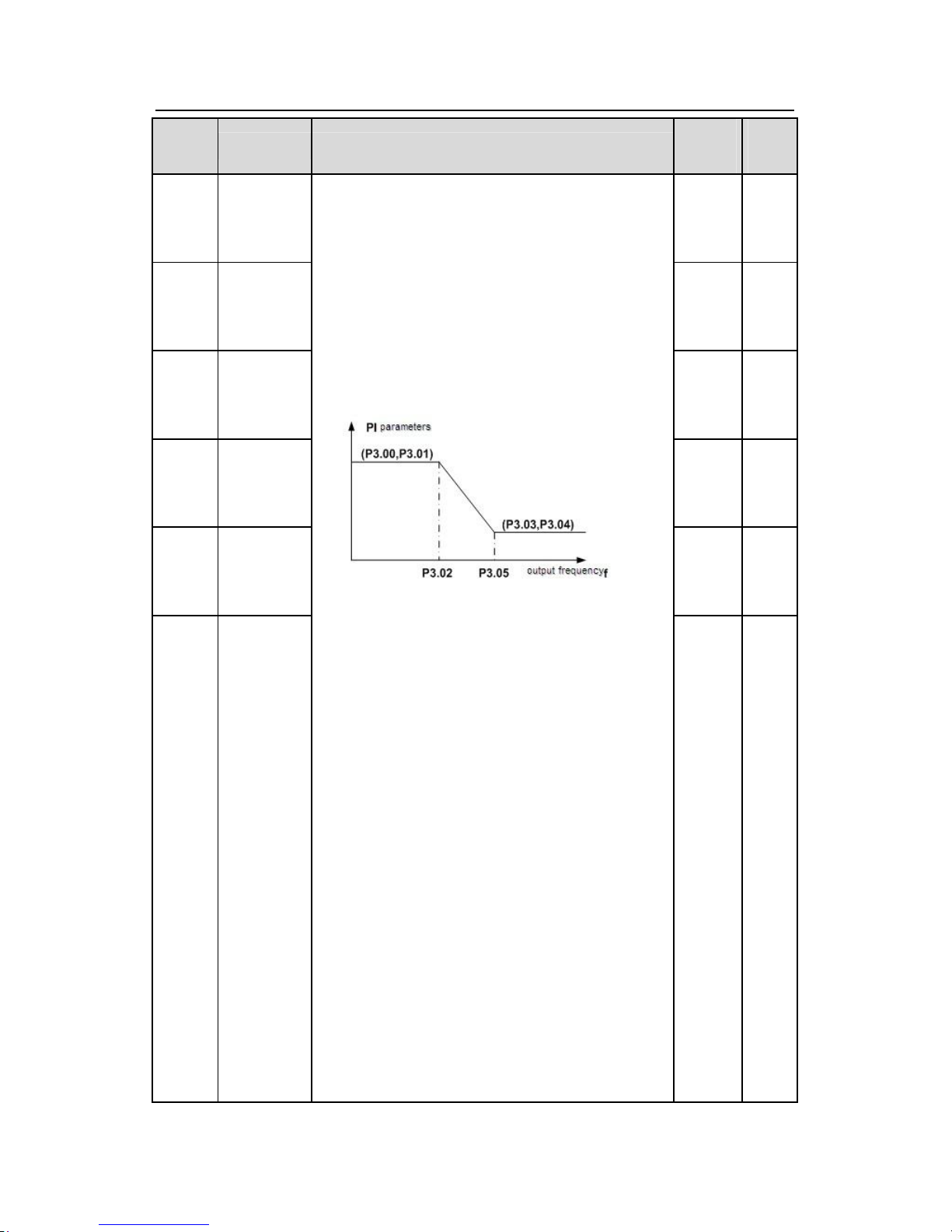
Goodrive300 inverters Function codes
67
Functio
n code
Name Detailed instruction of parameters
Default
value
Modif
y
P03.00
Speed loop
proportional
gain1
20.0 ○
P03.01
Speed loop
integral
time1
0.200s ○
P03.02
Low
switching
frequency
5.00Hz ○
P03.03
Speed loop
proportional
gain 2
20.0 ○
P03.04
Speed loop
integral
time
2
0.200s ○
P03.05
High
switching
frequency
The parameters P03.00~P03.05 only apply
to vector
control mode. Below the switching frequency
1(P03.02), the speed loop PI parameters are:
P03.00 and P03.01. Above the switching frequency
2(P03.05), the speed loop PI parameters are:
P03.03 and P03.04. PI parameters are gained
according to the linear change of two groups of
parameters. It is shown as below:
Setting the proportional coefficient and integral time
of the adjustor and change the dynamic response
performance of vector control speed loop. I
ncreasing
the proportional gain and decreasing the integral
time can speed up the dynamic response of the
speed loop. But too high proportional gain and too
low integral time may cause system vibration and
overshoot. Too low proportional gain may cause
system vibration and speed static deviation.
PI has a close relationship with the inertia of the
system. Adjust on the base of PI according to
different loads to meet various demands.
The setting range of P03.00:0~200.0
The setting range of P03.01:0.001~10.000s
The setting range of P03.02:0.00Hz~P03.05
The setting range of P03.03:0~200.0
The setting range of P03.04:0.001~10.000s
10.00H
z
○
Page 69
Goodrive300 inverters Function codes
68
Functio
n code
Name Detailed instruction of parameters
Default
value
Modif
y
The setting range of P03.05:P03.02~P00.03(the
Max. frequency)
P03.06
Speed loop
output filter
0~8( corresponds to 0~28/10ms) 0 ○
P03.07
Vector
control
electromotio
n slip
compensatio
n coefficient
100%
○
P03.08
Vector
control brake
slip
compensatio
n coefficient
Slip compensation coefficient is used to adjust the
slip frequency of the vector control and improve the
speed control accuracy of the system. Adjusting the
parameter properly can control the speed
steady-state error.
Setting range:50%~200%
100%
○
P03.09
Current loop
percentage
coefficient P
1000
○
P03.10
Current loop
integral
coefficient 1
Note:
1 These two parameters adjust the PI adjustment
parameter of the current loop which affects the
dynamic response speed and control accuracy
directly. Generally, users do not need to change the
default value.
2 Only apply to the vector control mode without PG
0(P00.00=0).
Setting range:0~65535
1000
○
P03.11
Torque
setting
method
This parameter is used to enable the torque control
mode, and set the torque setting means.
0:Torque control is invalid
1:Keypad setting torque(P03.12)
2:Analog AI1 setting torque
3:Analog AI2 setting torque
4:Analog AI3 setting torque
5:Pulse frequency HDI setting torque
6: Multi-stage torque setting
7:MODBUS communication setting torque
0 ○
Page 70
Goodrive300 inverters Function codes
69
Functio
n code
Name Detailed instruction of parameters
Default
value
Modif
y
8:PROFIBUS communication setting torque
9:Ethernet communication setting torque
10:CAN communication setting torque
Note: 100% of Setting methods 2~10, corresponds
to three times of the rated current of the motor.
P03.12
Keypad
setting
torque
Setting range: -300.0%~300.0%(motor rated current) 50.0%
○
P03.13
Torque given
filter time
0.000~10.000s 0.100s
○
P03.14
Torque
control
forward
rotation
upper-limit
frequency
setting
source
selection
0
○
P03.15
Torque
control
reverse
rotation
upper-limit
frequency
keypad
defined value
0:keypad setting upper-limit frequency(P03.16 sets
P03.14,P03.17 sets P03.15)
1:Analog AI1 setting upper-limit frequency
2:Analog AI2 setting upper-limit frequency
3:Analog AI3 setting upper-limit frequency
4:Pulse frequency HDI setting upper-limit frequency
5:Multi-stage setting upper-limit frequency
6:MODBUS communication setting upper-limit
frequency
7:PROFIBUS communication setting upper-limit
frequency
8:Ethernet communication setting upper-limit
frequency
9:CAN communication setting upper-limit frequency
Note:setting method 1~9, 100% corresponds to the
maximum frequency
0 ○
P03.16
Torque
control
forward
rotation
upper-limit
frequency
This function is used to set the upper limit of the
frequency. P03.16 sets the value of P03.14; P03.17
sets the value of P03.15.
Setting range:0.00 Hz~P00.03 (the Max. output
frequency)
50.00
Hz
○
Page 71
Goodrive300 inverters Function codes
70
Functio
n code
Name Detailed instruction of parameters
Default
value
Modif
y
keypad
defined value
P03.17
Torque
control
reverse
rotation
upper-limit
frequency
keypad
defined value
50.00
Hz
○
P03.18
Electromotio
n torque
upper-limit
setting
source
selection
0
○
P03.19
Braking
torque
upper-limit
setting
source
selection
This function code is used to select the
electromotion and braking torque upper-limit setting
source selection.
0:Keypad setting upper-limit frequency(P03.20 sets
P03.18,P03.21 sets P03.19)
1:Analog AI1 setting upper-limit torque
2:Analog AI2 setting upper-limit torque
3:Analog AI3 setting upper-limit torque
4:Pulse frequency HDI setting upper-limit torque
5:MODBUS communication setting upper-limit
torque
6:PROFIBUS communication setting upper-limit
torque
7:Ethernet communication setting upper-limit torque
8:CAN communication setting upper-limit torque
Note:setting method 1~9,100% corresponds to
three
times of the motor current.
0
○
P03.20
Electromotio
n torque
upper-limit
keypad
setting
The function code is used to set the limit of the
torque.
Setting range:0.0~300.0%(motor rated current)
180.0% ○
Page 72
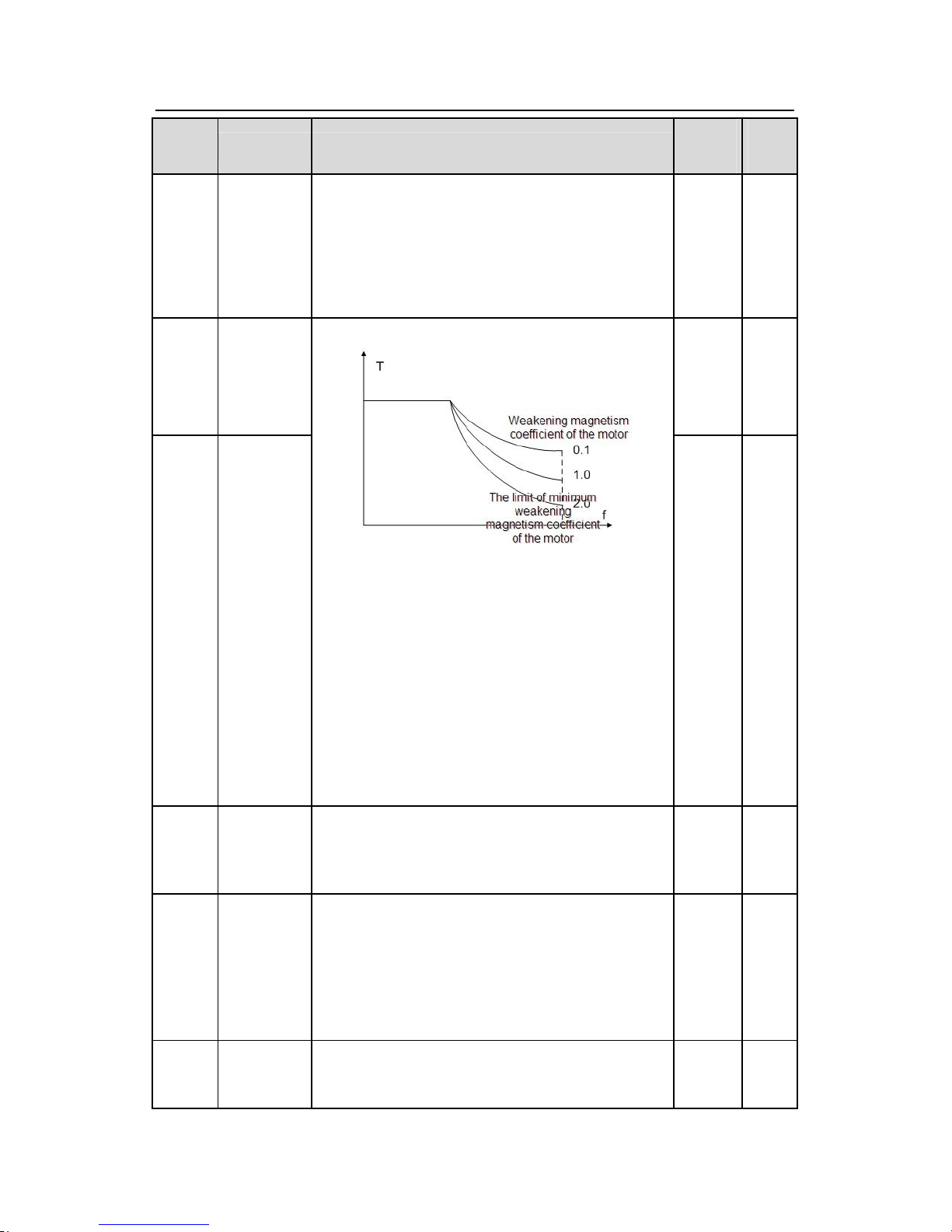
Goodrive300 inverters Function codes
71
Functio
n code
Name Detailed instruction of parameters
Default
value
Modif
y
P03.21
Braking
torque
upper-limit
keypad
setting
180.0% ○
P03.22
Weakening
coefficient in
constant
power zone
0.3 ○
P03.23
The lowest
weakening
point in
Constant
power zone
The usage of motor in weakening control.
Function code P03.22 and P03.23 are effective at
constant power. The motor will enter into the
weakening state wh
en the motor runs at rated
speed. Change the weakening curve by modifying
the weakening control coefficienct. The bigger the
weakening control coefficienct is, the steeper the
weak curve is.
The setting range of P03.22:0.1~2.0
The setting range of P03.23:10%~100%
20%
○
P03.24
Max. voltage
limit
P03.24 set the Max. Voltage of the inverter, which is
dependent on the site situation.
The setting range:0.0~120.0%
100.0% ◎
P03.25
Pre-exciting
time
Preactivate the motor when the inverter starts up.
Build up a magnetic field inside the inverter to
improve the torque performance during the starting
process.
The setting time:0.000~10.000s
0.300s ○
P03.26
Weak
magnetic
0~8000
Note: P03.24~P03.26 are invalid for vector mode.
1000
○
Page 73
Goodrive300 inverters Function codes
72
Functio
n code
Name Detailed instruction of parameters
Default
value
Modif
y
proportional
gain
P03.27
Vector
control
speed
display
selection
0: Display the actual value
1: Display the setting value
0 ○
P04 Group V/F control
P04.00
Motor 1V/F
curve setting
These function codes define the V/F curve of
Goodrive300 motor 1 to meet the need of different
loads.
0:Straight line V/F curve;applying to the constant
torque load
1:Multi-dots V/F curve
2:1.3th power low torque V/F curve
3:1.7th power low torque V/F curve
4:2.0th power low torque V/F curve
Curves 2~4 apply to the torque loads such as fans
and water pumps. U
sers can adjust according to the
features of the loads to achieve a best
energy-consuming effect.
5:Customized V/F(V/F separation);
on this mode, V
and F can be separated from f and f can be adjuste
d
through the frequency given channel set by P00.06
or the voltage given channel set by P04.27 to
change the feature of the curve.
Note:Vb in the below picture is the motor rated
voltage and fb is the motor rated frequency.
0 ◎
Page 74
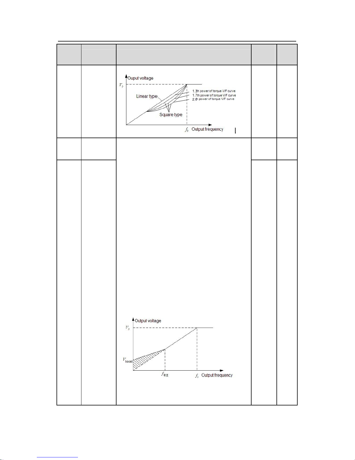
Goodrive300 inverters Function codes
73
Functio
n code
Name Detailed instruction of parameters
Default
value
Modif
y
P04.01
Motor 1
torque bo
ost
0.0%
○
P04.02
Motor 1
torque
boost
close
Torque
boost to the output voltage for the features of
low frequency torque. P04.01 is for the Max. Output
voltage Vb.
P04.02 defines the percentage of closing frequency
of manual torque to fb.
Torque boost should be selected according to the
load. The bigger the load is
, the bigger the torque is.
Too big torque boost is inappropriate because the
motor will run with over magnetic, and the current of
the inverter will increase to add the temperature of
the inverter and decrease the efficiency.
When the torque boost is set to 0.0%, the inverter is
automatic torque boost.
Torque boost threshold: on this frequency point, the
torque boost is effective, but over this frequency
point, the torque boost is ineffective.
The setting range of
P04.01:0.0%:(automatic)0.1%~10.0%
20.0% ○
Page 75
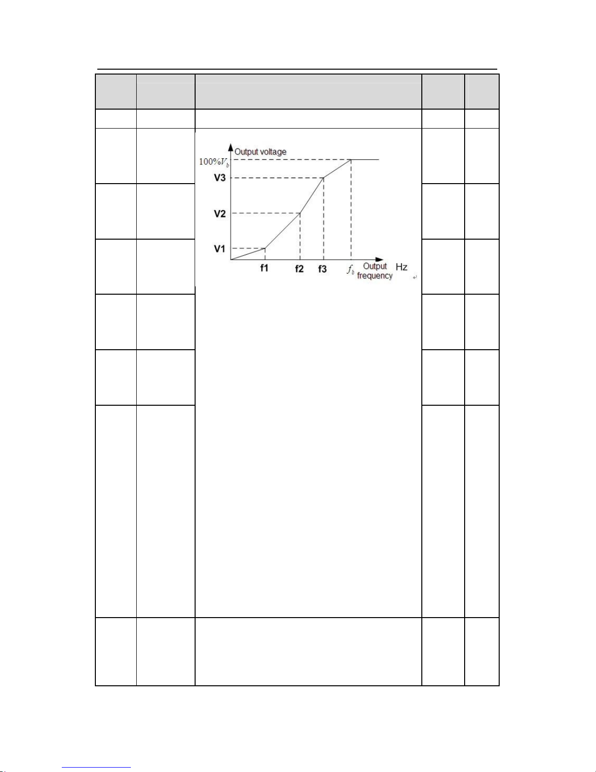
Goodrive300 inverters Function codes
74
Functio
n code
Name Detailed instruction of parameters
Default
value
Modif
y
The setting range of P04.02:0.0%~50.0%
P04.03
Motor 1V/F
Frequency
point 1
0.00Hz ○
P04.04
Motor 1 V/F
Voltage
point 1
00.0% ○
P04.05
Motor 1 V/F
Frequency
point 2
00.00H
z
○
P04.06
Motor 1 V/F
voltage point
2
00.0% ○
P04.07
Motor 1 V/F
Frequency
point 3
00.00H
z
○
P04.08
Motor 1 V/F
voltage point
3
When P04.00 =1, the user can set V//F curve
through P04.03~P04.08.
V/F is generally set according to the load of the
motor.
Note:V1<V2<V3,f1<f2<f3. Too high low
frequency voltage will heat the motor excessively or
damage. The inverter may loss the overcurrent
speed or overcurrent protection.
The setting range of P04.03: 0.00Hz~P04.05
The setting range of P04.04:0.0%~110.0%
The setting range of P04.05:P04.03~ P04.07
The setting range of P04.06:0.0%~110.0%(the rated
voltage of motor 1)
The setting range of P04.07:P04.05~ P02.02(the
rated frequency of motor 1) or P04.05~ P02.16(the
rated frequency of motor 1)
The setting range of P04.08:0.0%~110.0%(the rated
voltage of motor 1)
00.0% ○
P04.09
Motor 1 V/F
slip
compensatio
n gain
This function code is used to compensate the
change of the rotation speed caused by load during
compensation V/F control to improve the rigidity of
the motor. It can be set to the rated
slip frequency of
0.0%
○
Page 76
Goodrive300 inverters Function codes
75
Functio
n code
Name Detailed instruction of parameters
Default
value
Modif
y
the motor which is counted as below:
△f=fb-n*p/60
Of which, fb is the rated frequency of the motor, its
function code is P02.01; n is the rated rotating
speed
of the motor and its function code is P02.02;p
is the
pole pair of the motor. 100.0% corresponds to the
rated slip frequency△f.
Setting range:0.0~200.0%
P04.10
Motor 1 low
frequency
vibration
control factor
10 ○
P04.11
Motor 1 high
frequency
vibration
control factor
10 ○
P04.12
Motor 1
vibration
control
threshold
In the V/F control mode, current fluctuation may
occur to the motor on some frequency, especially the
motor with big power. The motor can not run stably
or overcurrent may occur. These phenomena
can be
canceled by adjusting this parameter.
The setting range of P04.10:0~100
The setting range of P04.11:0~100
The setting range of P04.12:0.00Hz~P00.03(the
Max. frequency)
30.00
Hz
○
P04.13
Motor 2 V/F
curve setting
0 ◎
P04.14
Motor 2
torque boost
0.0%
○
P04.15
Motor 2
torque
threshold
20.0% ○
P04.16
Motor 2V/F
frequency
point 1
0.00Hz ○
P04.17
Motor 2V/F
voltage point
1
00.0% ○
P04.18 Motor 2V/F
This group of parameters defines the V/F setting
means of Goodrive300 motor 2 to meet the features
of different loads. See P04.00~P04.12 for the
detailed function code instruction.
Note: P04 group contains two sets of V/F
parameters of the motor which cannot display
simultaneously. Only the selected V/F
parameter can
be shown. The motor selection can be defined by
terminals function “the shift between motor 1 and
motor 2”
00.00H ○
Page 77
Goodrive300 inverters Function codes
76
Functio
n code
Name Detailed instruction of parameters
Default
value
Modif
y
frequency
point 2
z
P04.19
Motor 2V/F
voltage point
2
00.0% ○
P04.20
Motor 2V/F
frequency
point 3
00.00H
z
○
P04.21
Motor 2V/F
voltage point
3
00.0% ○
P04.22
Motor 2 V/F
slip
compensatio
n gain
0.0%
○
P04.23
Motor 2 low
frequency
vibration
control factor
10 ○
P04.24
Motor 2 high
frequency
vibration
control factor
10 ○
P04.25
Motor 2
vibration
control
threshold
In the V/F control mode, current fluctuation may
occur to the motor on some frequency, especially the
motor with big power. The motor can not run stably
or overcurrent may occur. These phenomena
can be
canceled by adjusting this parameter.
The setting range of P04.23:0~100
The setting range of P04.24:0~100
The setting range of P04.25:0.00Hz~P00.03(the
Max. frequency)
30.00
Hz
○
P04.26
Energy-savin
g operation
selection
0:No operation
1:Automatic energy-saving operation
Motor on the light load conditions, automatically
adjusts the output voltage to save energy
0 ◎
P04.27
Voltage
Setting
Channel
Select the output setting channel at V/F curve
separation.
0: Keypad setting voltage: the output voltage is
0 ○
Page 78
Goodrive300 inverters Function codes
77
Functio
n code
Name Detailed instruction of parameters
Default
value
Modif
y
determined by P04.28.
1:AI1 setting voltage ;
2:AI2 setting voltage;
3:AI3 setting voltage;
4:HDI1 setting voltage;
5:Multi-stage speed setting voltage;
6:PID setting voltage;
7:MODBUS communication setting voltage;
8:PROFIBUS communication setting voltage;
9:Ethernet communication setting voltage;
10:CAN communication setting voltage;
Note:100% corresponds to the rated voltage of the
motor.
P04.28
Keypad
setting
voltage
The function code is the voltage digital set value
when the
voltage setting channel is selected as
“keypad selection”
The setting range:0.0%~100.0%
100.0% ○
P04.29
Voltage
increasing
time
5.0s ○
P04.30
Voltage
decreasing
time
Voltage increasing time is the time when the
inverter
accelerates from the output minimum voltage to the
output maximum voltage.
Voltage decreasing time is the time when the
inverter
decelerates from the output maximum
voltage to the
output minimum voltage.
The setting range:0.0~3600.0s
5.0s ○
P04.31
Maximum
output
voltage
100.0% ◎
P04.32
Minimum
output
voltage
Set the upper and low limit of the output voltage.
The setting range of P04.31:P04.32~100.0%(the
rated voltage of the motor)
The setting range of P04.32:0.0%~ P04.31(the rated
voltage of the motor)
0.0%
◎
Page 79
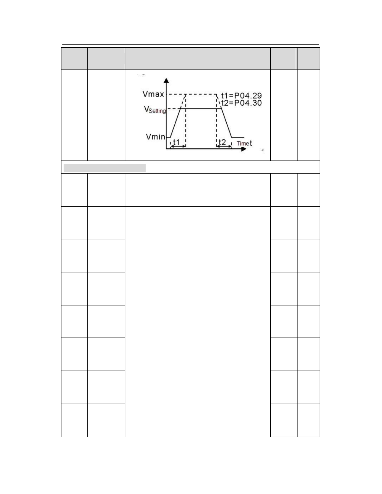
Goodrive300 inverters Function codes
78
Functio
n code
Name Detailed instruction of parameters
Default
value
Modif
y
P05 Group Input terminals
P05.00
HDI input
type
selection
0:HDI is high pulse input. See P05.49~P05.54
1:HDI is switch input. See P05.09
0 ◎
P05.01
S1 terminals
function
selection
1 ◎
P05.02
S2 terminals
function
selection
4 ◎
P05.03
S3 terminals
function
selection
7 ◎
P05.04
S4 terminals
function
selection
0 ◎
P05.05
S5 terminals
function
selection
0 ◎
P05.06
S6 terminals
function
selection
0 ◎
P05.07
S7 terminals
function
selection
0: No function
1: Forward rotation operation
2: Reverse rotation operation
3: 3-wire control operation
4: Forward rotation jogging
5: Reverse rotation jogging
6: Coast to stop
7: Fault reset
8: Operation pause
9: External fault input
10:Increasing frequency setting(UP)
11:Decreasing frequency setting(DOWN)
12:Cancel the frequency change setting
13:Shift between A setting and B setting
14:Shift between combination setting and A setting
15:Shift between combination setting and B setting
16:Multi-stage speed terminal 1
17:Multi-stage speed terminal 2
18:Multi-stage speed terminal 3
19:Multi- stage speed terminal 4
20:Multi- stage speed pause
0 ◎
Page 80
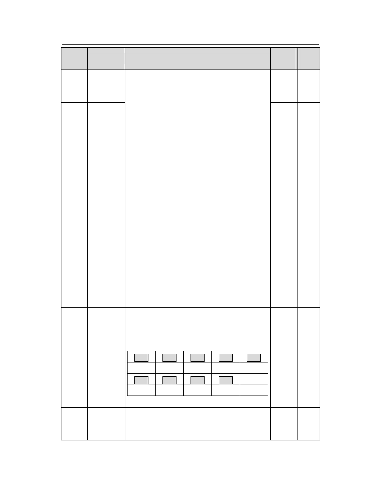
Goodrive300 inverters Function codes
79
Functio
n code
Name Detailed instruction of parameters
Default
value
Modif
y
P05.08
S8 terminals
function
selection
0 ◎
P05.09
HDI terminal
function
selection
21:ACC/DEC time option1
22:ACC/DEC time option2
23:Simple PLC stop reset
24:Simple PLC pause
25:PID control pause
26:Traverse Pause(stop at the current frequency)
27:Traverse reset(return to the center frequency)
28:Counter reset
29:Torque control prohibition
30:ACC/DEC prohibition
31:Counter trigger
32:Length reset
33:Cancel the frequency change setting temporarily
34:DC brake
35:Shift the motor 1 into motor 2
36:Shift the command to the keypad
37:Shift the command to the terminals
38:Shift the command to the communication
39:Pre-magnetized command
40:Clear the power
41:Keep the power
42~63:Reserved
0 ◎
P05.10
Polarity
selection of
the input
terminals
The function code is used to set the polarity of the
input terminals.
Set the bit to 0, the input terminal is anode.
Set the bit to 1, the input terminal is cathode.
BIT0
BIT2 BIT3 BIT4 BIT5
S1 S2 S3 S4 S5
BIT6
BIT7 BIT8 BIT9
S6 S7 S8 HDI
The setting range:0x000~0x1FF
0x000
○
P05.11
ON-OFF
filter time
Set the sample filter time of S1~S8 and HDI
terminals. If the interference is strong, increase the
parameter to avoid the disoperation.
0.010s ○
Page 81
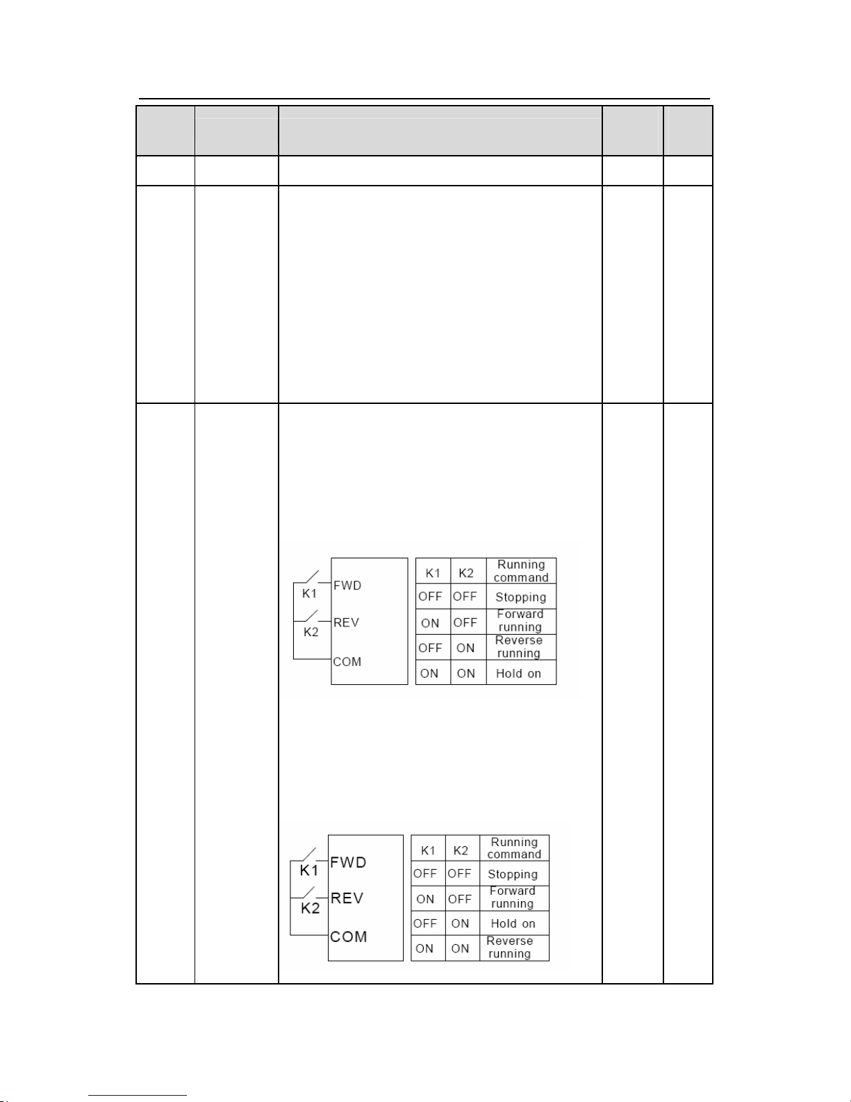
Goodrive300 inverters Function codes
80
Functio
n code
Name Detailed instruction of parameters
Default
value
Modif
y
0.000~1.000s
P05.12
Virtual
terminals
setting
Enable the input function of virtual terminals at the
communication mode.
0:Virtual terminals is invalid
1:MODBUS communication virtual terminals are
valid
2:PROFIBUS communication virtual terminals are
valid
3: Ethernet communication virtual terminals are valid
4: CAN communication virtual terminals are valid
0 ◎
P05.13
Terminals
control
running
mode
Set the operation mode of the terminals control
0:2-wire control 1, comply the enable with the
direction. This mode is widely used. It determines
the rotation direction by the defined FWD and REV
terminals command.
1:2-wire control 2;Separate the enable from the
direction. FWD defined by this mode is the enabling
ones. The direction depends on the state of the
defined REV.
0 ◎
Page 82
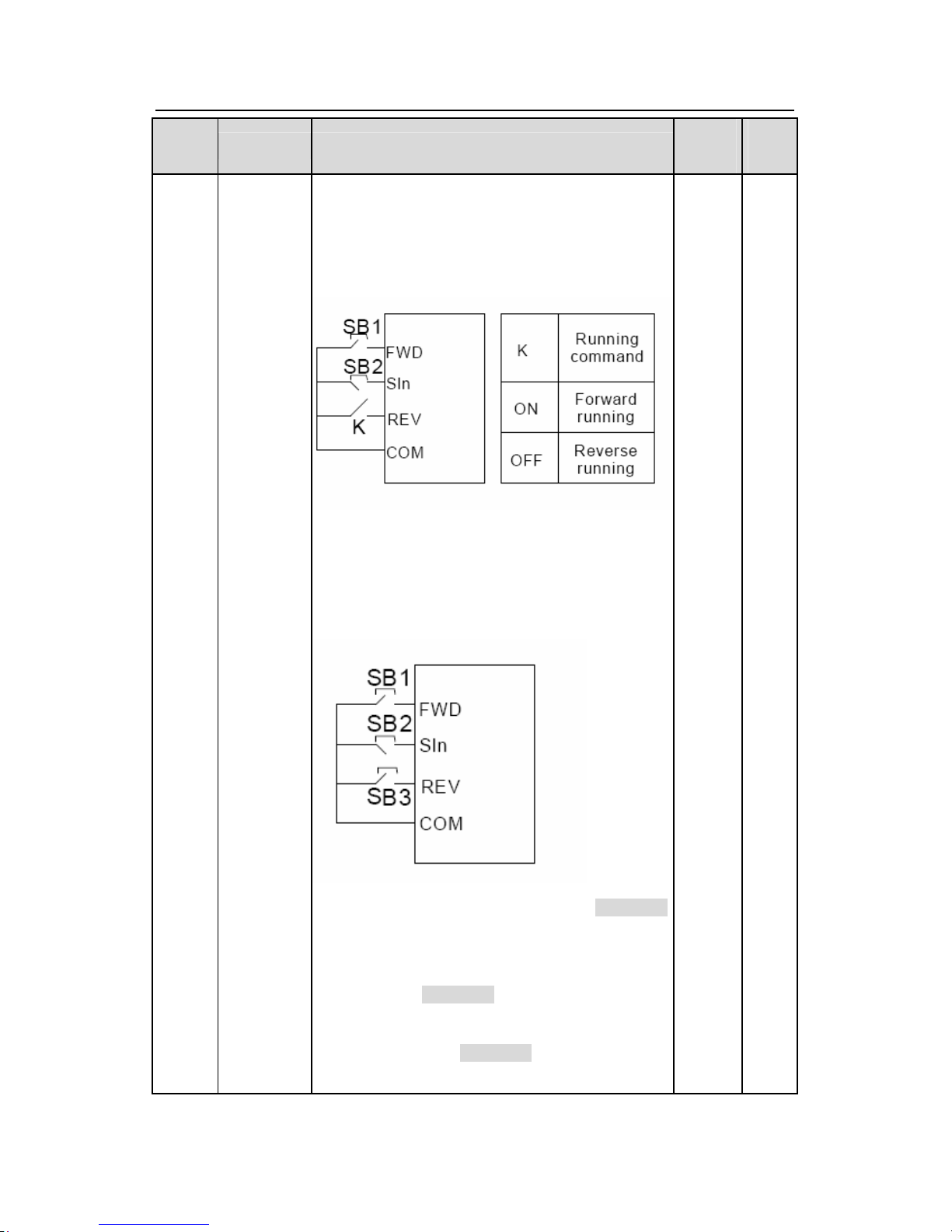
Goodrive300 inverters Function codes
81
Functio
n code
Name Detailed instruction of parameters
Default
value
Modif
y
2:3-wire control 1; Sin
is the enabling terminal on this
mode, and the running command is caused by FWD
and the direction is controlled by REV. Sin is
natural closed.
3:3-wire control 2; Sin
is the enabling terminal on this
mode, and the running command is caused by SB1
or SB3 and both of them control the running
direction.NC SB2 generates the stop command.
Note: for the 2-wire running mode, when FWD/REV
terminal is effective, the inverter stop because of the
stopping command from other sources, even the
control terminal FWD/REV keeps effective; the
inverter won’t work when the stopping command is
canceled. Only when FWD/REV is relaunched, the
inverter can start again. For example, the effective
Page 83
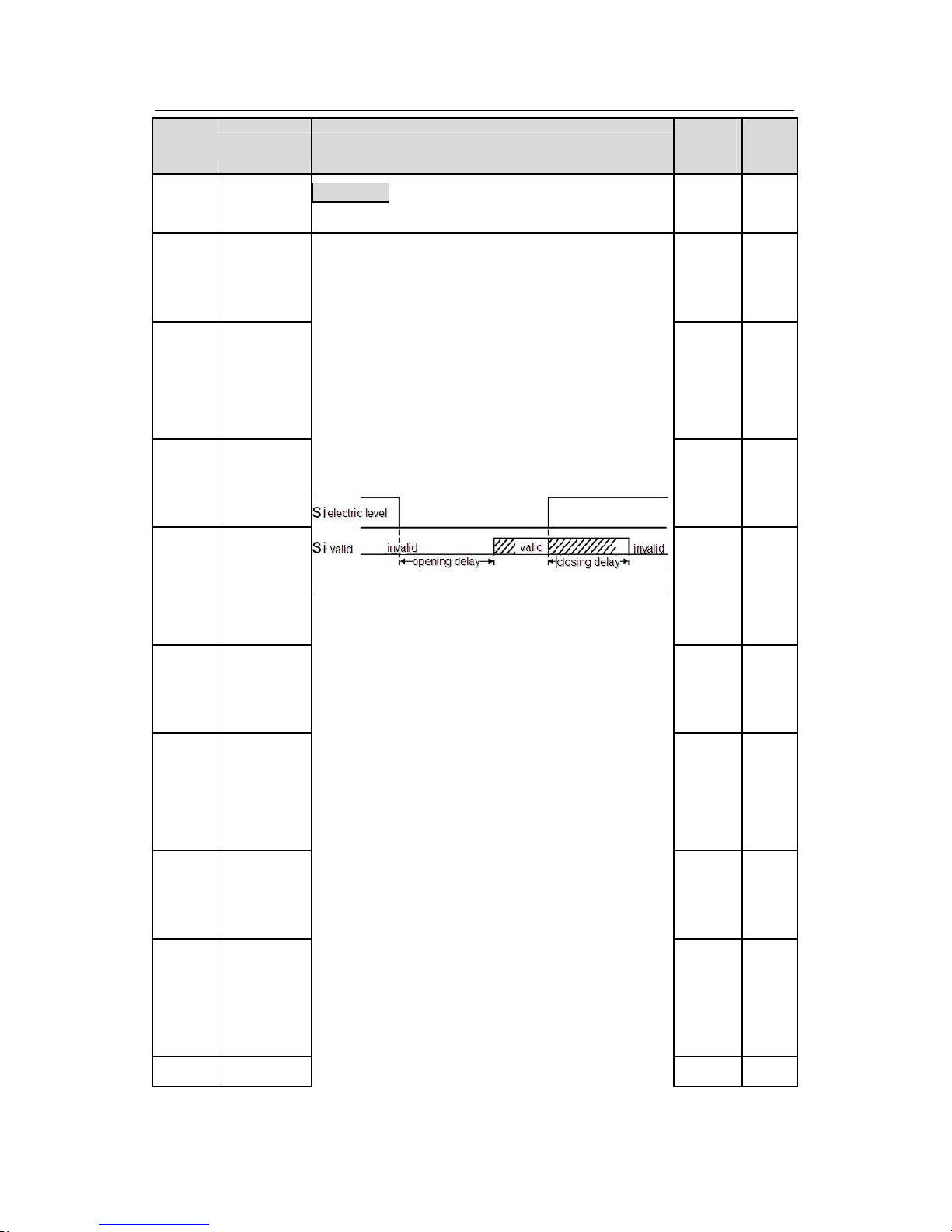
Goodrive300 inverters Function codes
82
Functio
n code
Name Detailed instruction of parameters
Default
value
Modif
y
STOP/RSTstop when PLC signal cycles stop,
fixed-length stop and terminal control (see P07.04).
P05.14
S1 terminal
switching-
on
delay time
0.000s ○
P05.15
S1
terminal
switching-
off
delay time
0.000s ○
P05.16
S2 terminal
switching-
on
delay time
0.000s ○
P05.17
S2
terminal
switching-
off
delay time
0.000s ○
P05.18
S3 terminal
switching-
on
delay time
0.000s ○
P05.19
S3
terminal
switching-
off
delay time
0.000s ○
P05.20
S4 terminal
switching-
on
delay time
0.000s ○
P05.21
S4
terminal
switching-
off
delay time
0.000s ○
P05.22
S5
The function code defines the corresponding delay
time of electrical level of the programmable terminals
from switching on to switching off.
Setting range:0.000~50.000s
0.000s ○
Page 84
Goodrive300 inverters Function codes
83
Functio
n code
Name Detailed instruction of parameters
Default
value
Modif
y
terminal
switching-
on
delay time
P05.23
S5
terminal
switching-
off
delay time
0.000s ○
P05.24
S6
terminal
switching-
on
delay time
0.000s ○
P05.25
S6
terminal
switching-
off
delay time
0.000s ○
P05.26
S7
terminal
switching-
on
delay time
0.000s ○
P05.27
S7
terminal
switching-
off
delay time
0.000s ○
P05.28
S8
terminal
switching-
on
delay time
0.000s ○
P05.29
S8
terminal
switching-
off
delay time
0.000s ○
Page 85
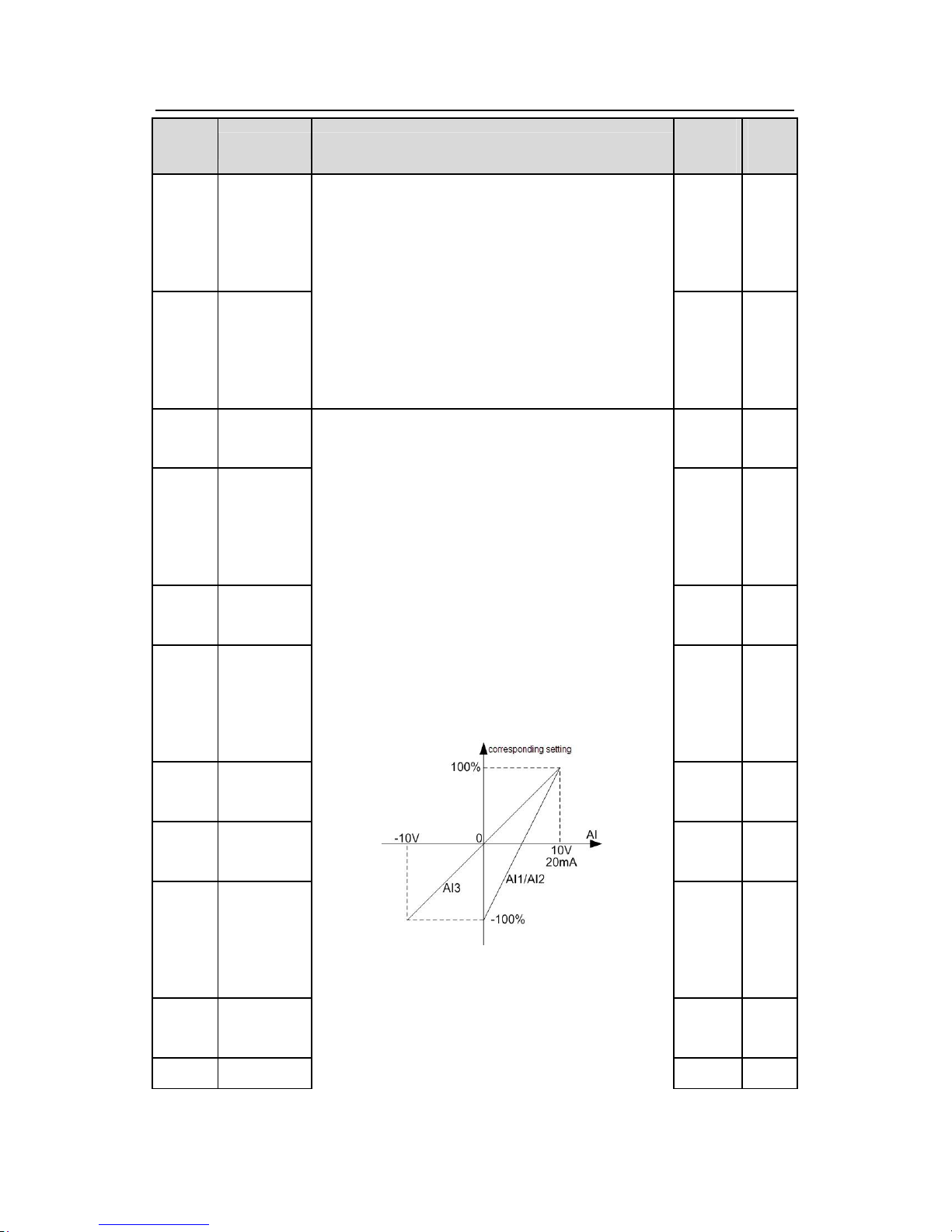
Goodrive300 inverters Function codes
84
Functio
n code
Name Detailed instruction of parameters
Default
value
Modif
y
P05.30
HDI
terminal
switching-
on
delay time
0.000s ○
P05.31
HDI
terminal
switching-
off
delay time
0.000s ○
P05.32
Lower limit of
AI1
0.00V
○
P05.33
Correspondi
ng setting of
the lower
limit of AI1
0.0%
○
P05.34
Upper limit of
AI1
10.00V ○
P05.35
Correspondi
ng setting of
the upper
limit of AI1
100.0% ○
P05.36
AI1 input
filter time
0.100s ○
P05.37
Lower limit of
AI2
0.00V
○
P05.38
Correspondi
ng setting of
the lower
limit of AI2
0.0%
○
P05.39
Upper limit of
AI2
10.00V ○
P05.40 Correspondi
The function code defines the relationship between
the analog input voltage and its corresponding set
value. If the analog input voltage beyond the set
minimum or maximum input value, the inverter will
count at the minimum or maximum one.
When the analog input is the current input, the
corresponding voltage of 0~20mA is 0~10V.
In different cases, the corresponding rated value of
100.0% is different. See the application for detailed
information.
The figure below illustrates different applications:
Input filter time: this parameter is used to adjust the
sensitivity of the analog input. Increasing the value
properly can enhance the anti-interference of the
analog, but weaken the sensitivity of the analog
input.
100.0% ○
Page 86
Goodrive300 inverters Function codes
85
Functio
n code
Name Detailed instruction of parameters
Default
value
Modif
y
ng setting of
the upper
limit of AI2
P05.41
AI2 input
filter time
0.100s ○
P05.42
Lower limit of
AI3
-10.00V ○
P05.43
Correspondi
ng setting of
the lower
limit of AI3
-100.0
%
○
P05.44
Middle value
of AI3
0.00V
○
P05.45
Correspondi
ng middle
setting of
AI3
0.0%
○
P05.46
Upper limit of
AI3
10.00V ○
P05.47
Correspondi
ng setting of
the upper
limit of AI3
100.0% ○
P05.48
AI3 input
filter time
Note: Analog AI1 and AI2 can support 0~10V or
0~20mA input, when AI1 and AI2 selects 0~20mA
input, the corresponding voltage of 20mA is 5V. AI3
can support the output of -10V~+10V.
The setting range of P05.32:0.00V~P05.34
The setting range of P05.33:-100.0%~100.0%
The setting range of P05.34:P05.32~10.00V
The setting range of P05.35:-100.0%~100.0%
The setting range of P05.36:0.000s~10.000s
The setting range of P05.37:0.00V~P05.39
The setting range of P05.38:-100.0%~100.0%
The setting range of P05.39:P05.37~10.00V
The setting range of P05.40:-100.0%~100.0%
The setting range of P05.41:0.000s~10.000s
The setting range of P05.42:-10.00V~P05.44
The setting range of P05.43:-100.0%~100.0%
The setting range of P05.44:P05.42~P05.46
The setting range of P05.45:-100.0%~100.0%
The setting range of P05.46:P05.44~10.00V
The setting range of P05.47:-100.0%~100.0%
The setting range of P05.48:0.000s~10.000s
0.100s ○
P05.49
HDI
high-speed
pulse input
function
selection
The function selection when HDI terminals is
high-speed pulse input
0:Frequency setting input, frequency setting source
1:Counter input, high-speed pulse counter input
terminals
2:Length counting input, length counter input
0 ◎
Page 87
Goodrive300 inverters Function codes
86
Functio
n code
Name Detailed instruction of parameters
Default
value
Modif
y
terminals
P05.50
Lower limit
frequency of
HDI
0.00 KHz ~ P05.52
0.00KH
z
○
P05.51
Correspondi
ng setting
of
HDI low
frequency
setting
-100.0%~100.0% 0.0%
○
P05.52
Upper limit
frequency of
HDI
P05.50 ~50.00KHz
50.00K
Hz
○
P05.53
Correspondi
ng setting of
upper limit
frequency of
HDI
-100.0%~100.0% 100.0% ○
P05.54
HDI
frequency
input filter
time
0.000s~10.000s 0.100s ○
P06 Group Output terminals
P06.00 HDO
output
The function selection of the high-
speed pulse output
terminals.
0: Open collector pole high speed pulse output: The
Max.pulse frequency is 50.0kHz. See
P06.27~P06.31 for detailed information of the
related functions.
1: Open collector pole output. See P06.02 for
detailed information of the related functions.
0 ◎
P06.01 Y output 0:Invalid 0 ○
Page 88
Goodrive300 inverters Function codes
87
Functio
n code
Name Detailed instruction of parameters
Default
value
Modif
y
P06.02 HDO
output
0 ○
P06.03
Relay RO1
output
1 ○
P06.04
Relay RO2
output
1:In operation
2:Forward rotation operation
3:Reverse rotation operation
4: Jogging operation
5:The inverter fault
6:Frequency degree test FDT1
7:Frequency degree test FDT2
8:Frequency arrival
9:Zero speed running
10:Upper limit frequency arrival
11:Lower limit frequency arrival
12:Ready for operation
13:Pre-magnetizing
14:Overload pre-alarm
15: Underload pre-alarm
16:Completion of simple PLC stage
17:Completion of simple PLC cycle
18:Setting count value arrival
19:Defined count value arrival
20:External fault valid
21:Length arrival
22:Running time arrival
23:MODBUS communication virtual terminals output
24:PROFIBUS communication virtual terminals
output
25: Ethernet communication virtual terminals output
26: CAN communication virtual terminals output
27~30: Reserved
5 ○
P06.05
Polarity
selection of
output
terminals
The function code is used to set the pole of the
output terminal.
When the current bit is set to 0, input terminal is
positive.
00 ○
Page 89
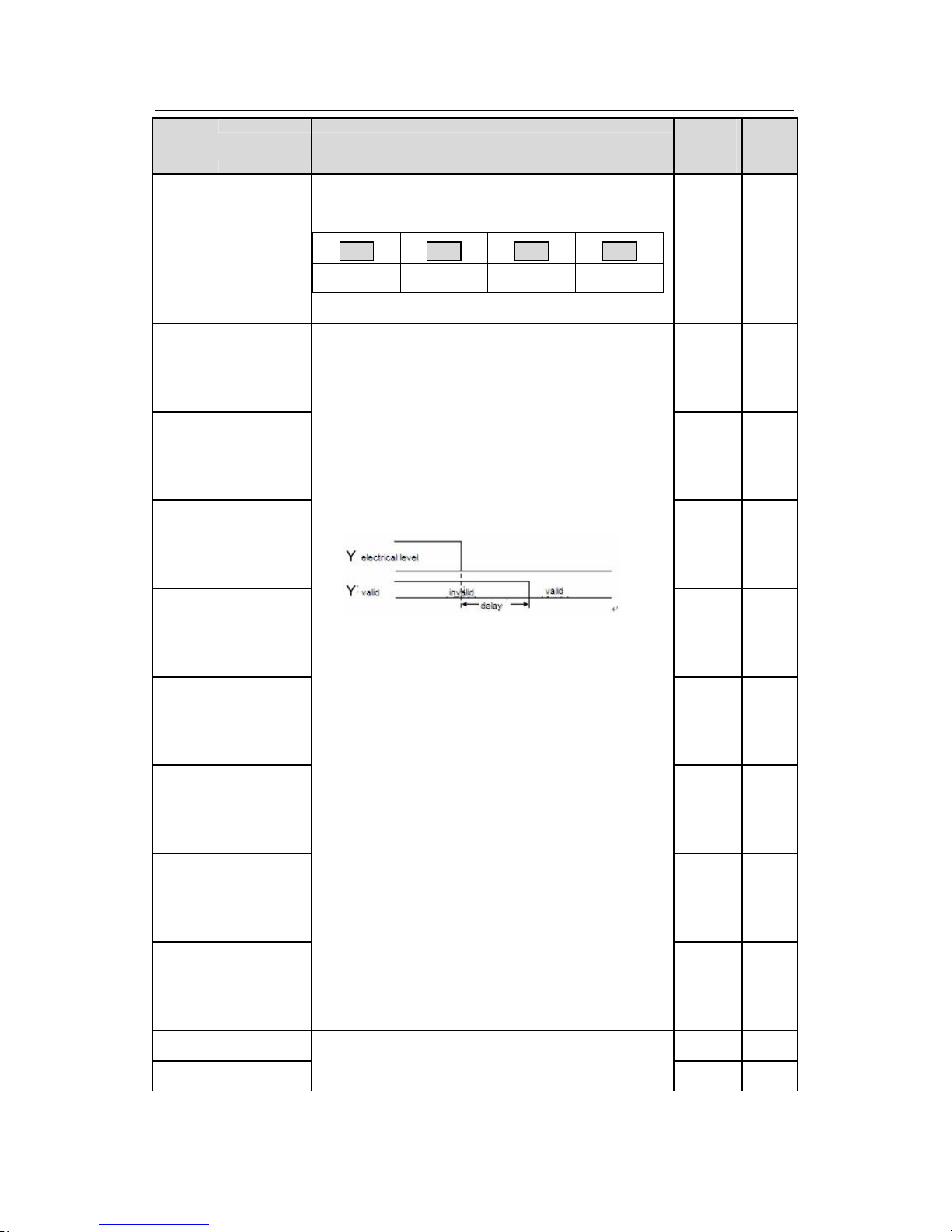
Goodrive300 inverters Function codes
88
Functio
n code
Name Detailed instruction of parameters
Default
value
Modif
y
When the current bit is set to 1, input terminal is
negative.
BIT0 BIT1 BIT2 BIT3
Y HDO RO1 RO2
Setting range:00~0F
P06.06
Y
switching-
on
delay time
0.000s ○
P06.07
Y
switching-
off
delay time
0.000s ○
P06.08
HDO
switching-
on
delay time
0.000s ○
P06.09
HDO
switching-
off
delay time
0.000s ○
P06.10
RO1
switching-
on
delay time
0.000s ○
P06.11
RO1
switching-
off
delay time
0.000s ○
P06.12
RO2
switching-
on
delay time
0.000s ○
P06.13
RO2
switching-
off
delay time
The function code defines the corresponding delay
time of the electrical level change during the
programmable terminal switching on and off.
The setting range :0.000~50.000s
Note: P06.08 and P06.08 are valid only when
P06.00=1.
0.000s ○
P06.14 AO1
output
0 ○
P06.15 AO2
output
0:Running frequency
1:Set frequency
0 ○
Page 90
Goodrive300 inverters Function codes
89
Functio
n code
Name Detailed instruction of parameters
Default
value
Modif
y
P06.16
HDO
high-speed
pulse output
selection
2:Ramp reference frequency
3:Running rotation speed
4:Output current (relative to the rated current of the
inverter)
5:Output current(relative to the rated current of the
motor)
6:Output voltage
7:Output power
8:Set torque value
9:Output torque
10:Analog AI1 input value
11:Analog AI2 input value
12:Analog AI3 input value
13:High speed pulse HDI input value
14:MODBUS communication set value 1
15:MODBUS communication set value 2
16:PROFIBUS communication set value 1
17:PROFIBUS communication set value 2
18: Ethernet communication set value 1
19: Ethernet communication set value 2
20: CAN communication set value 1
21: CAN communication set value 2
22:Torque current(relative to the rated current of the
motor)
23:Pre-magnetizing current(relative to the rated
current of the motor)
24:Reserved
0 ○
P06.17
Lower limit of
AO1
output
0.0%
○
P06.18 Correspondi
ng AO1
output to the
The above function codes define the relative
relationship between the output value and analog
output. When the output value exceeds the range of
set maximum or minimum output, it will count
according to the low-limit or upper-limit output.
0.00V
○
Page 91
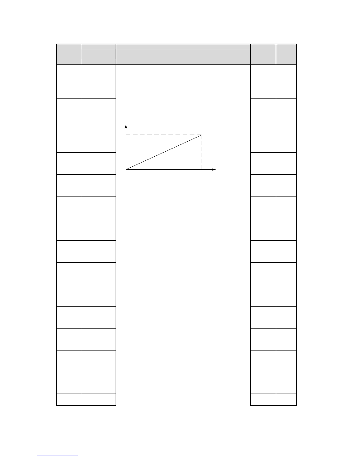
Goodrive300 inverters Function codes
90
Functio
n code
Name Detailed instruction of parameters
Default
value
Modif
y
lower limit
P06.19
Upper limit of
AO1 output
100.0% ○
P06.20
The
correspondin
g AO1
output
to the upper
limit
10.00V ○
P06.21
AO1 output
filter time
0.000s ○
P06.22
Lower limit of
AO2 output
0.0%
○
P06.23
Correspondi
ng AO2
output to the
lower limit
0.00V
○
P06.24
Upper limit of
AO2 output
100.0% ○
P06.25
Correspondi
ng AO2
output to the
upper limit
10.00V ○
P06.26
AO2 output
filter time
0.000s ○
P06.27
Lower limit of
HDO output
0.00% ○
P06.28
Correspondi
ng HDO
output to the
lower limit
0.0kHz ○
P06.29
Upper limit of
When the analog output is current output, 1mA
equals to 0.5V.
In different cases, the corresponding analog output
of 100% of the output value is different. See each
application for detailed information.
10 V( 20 mA )
0 .0 % 1 00 .0%
A
O
Setting range of P06.18 0.00V~10.00V
Setting range of P06.19 P06.17~100.0%
Setting range of P06.20 0.00V~10.00V
Setting range of P06.21 0.000s~10.000s
Setting range of P06.22 0.0%~P06.24
Setting range of P06.23 0.00V~10.00V
Setting range of P06.24 P06.22~100.0%
Setting range of P06.25 0.00V~10.00V
Setting range of P06.26 0.000s~10.000s
Setting range of P06.27 0.0%~P06.29
Setting range of P06.28 0.00~50.00kHz
Setting range of P06.29 P06.27~100.0%
Setting range of P06.30 0.00~50.00kHz
Setting range of P06.31 0.000s~10.000s
100.0% ○
Page 92
Goodrive300 inverters Function codes
91
Functio
n code
Name Detailed instruction of parameters
Default
value
Modif
y
HDO output
P06.30
Correspondi
ng HDO
output to the
upper limit
50.00k
Hz
○
P06.31
HDO output
filter time
0.000s ○
P07 Group Human-Machine Interface
P07.00
User’s
password
0~65535
The password protection will be valid when setting
any non-zero number.
00000: Clear the previous user’s password, and
make the password protection invalid.
After the set user’s password becomes valid, if the
password is incorrect, users cannot enter the
parameter menu. Only correct password can make
the user check or modify the parameters. Please
remember all users’ passwords.
Retreat editing state of the function codes and the
password protection will become valid in minute. If
the valid password is available, press PRG/ESCto
enter into the editing
state of the function codes, and
then “0.0.0.0.0” will be displayed. Unless input right
password, the operator can not enter into it.
Note: restoring to the default value can clear the
password, please use it with caution.
0 ○
P07.01
Parameter
copy
The function code determines the manner of
parameters copy.
0:No operation
1:Upload the local function parameter to the keypad
2:Download the keypad function parameter to local
0 ◎
Page 93
Goodrive300 inverters Function codes
92
Functio
n code
Name Detailed instruction of parameters
Default
value
Modif
y
address(including the motor parameters)
3:Download the keypad function parameter to local
address (excluding the motor parameter of P02, P12
group)
4:Download the keypad function parameters to local
address (only for the motor parameter of P02,P12
group)
Note: After completing the 1~4 operations, the
parameter will come back to 0 automatically; the
function of upload and download excludes the
factory parameters of P29.
P07.02
QUICK/JOG
function
selection
0:No function
1: Jogging running. Press QUICK/JOG to realize
the
jogging running.
2: Shift the display state by the shifting key. Press
QUICK/JOG
to shift the displayed function code from
right to left.
3: Shift between forward rotations and reverse
rotations. Press QUICK/JOG to shift the direction of
the frequency commands. This function is only valid
in the keypad commands channels.
4: Clear UP/DOWN settings. Press QUICK/JOG to
clear the set value of UP/DOWN.
5: Coast to stop. Press QUICK/JOG to coast to stop.
6: Shift the given manner of running commands.
Press QUICK/JOG to shift the given manner of
running commands.
7:Quick commission mode(committee according to
the non-factory parameter)
Note: Press QUICK/JOGto shift between forward
rotation and reverse rotation, the inverter does not
remember the state after shifting during
powering off.
1 ◎
Page 94
Goodrive300 inverters Function codes
93
Functio
n code
Name Detailed instruction of parameters
Default
value
Modif
y
The inverter will run in the running direction set
according to parameter P00.
13 during next powering
on.
P07.03
QUICK/JOG
the shifting
sequence
selection of
running
command
channel
When P07.06=6, set the shifting sequence of
running command channels.
0:Keypad control→terminals control
→communication control
1:Keypad control←→terminals control
2:Keypad control←→communication control
3:Terminals control←→communication control
0 ○
P07.04
STOP/RST
stop function
STOP/RST is an effective selection key of the stop
function. STOP/RST is effective in any state for the
fault reset.
0:Only valid for the panel control
1:Both valid for panel and terminals control
2:Both valid for panel and communication control
3:Valid for all control modes
0 ○
P07.05
The
parameter
selection 1
in
the running
state
0x0000~0xFFFF
BIT0:running frequency (Hz on)
BIT1:set frequency(Hz flickering)
BIT2:bus voltage (Hz on)
BIT3:output voltage(V on)
BIT4:output current(A on)
BIT5:running rotation speed (rpm on)
BIT6:output power(% on)
BIT7:output torque(% on)
BIT8:PID reference(% flickering)
BIT9:PID feedback value(% on)
BIT10:input terminals state
BIT11:output terminals state
BIT12:torque set value(% on)
BIT13:pulse counter value
0x03FF ○
Page 95
Goodrive300 inverters Function codes
94
Functio
n code
Name Detailed instruction of parameters
Default
value
Modif
y
BIT14:length value
BIT15:PLC and the current stage in multi-stage
speed
P07.06
The
parameter 2
in running
state
0x0000~0xFFFF
BIT0: analog AI1 value (V on)
BIT1: analog AI2 value (V on)
BIT2: analog AI3 value (V on)
BIT3: high speed pulse HDI frequency
BIT4: motor overload percentage (% on)
BIT5: the inverter overload percentage (% on)
BIT6: ramp frequency given value(Hz on)
BIT7: linear speed
BIT8: AC inlet current (A on)
BIT9~15:reserved
0x0000
P07.07
The
parameter in
the stop
state
0x0000~0xFFFF
BIT0:set frequency(Hz on, frequency flickering
slowly)
BIT1:bus voltage (V on)
BIT2:input terminals state
BIT3:output terminals state
BIT4:PID reference (% flickering)
BIT5:PID feedback value(% flickering)
BIT6:torque reference(% flickering)
BIT7:analog AI1 value(V on)
BIT8:analog AI2 value(V on)
BIT9: analog AI3 value(V on)
BIT10:high speed pulse HDI frequency
BIT11:PLC and the current stage in multi-stage
speed
BIT12:pulse counters
BIT13:length value
BIT14~BIT15:reserved
0x00FF ○
Page 96
Goodrive300 inverters Function codes
95
Functio
n code
Name Detailed instruction of parameters
Default
value
Modif
y
P07.08
Frequency
coefficient
0.01~10.00
Displayed frequency=running frequency* P07.08
1.00 ○
P07.09
Rotation
speed
coefficient
0.1~999.9%
Mechanical rotation speed =120*displayed running
frequency×P07.09/motor pole pairs
100.0% ○
P07.10
Linear speed
coefficient
0.1~999.9%
Linear speed= Mechanical rotation speed×P07.10
1.0%
○
P07.11
Rectifier
bridge
module
temperature
-20.0~120.0℃ ●
P07.12
Converter
module
temperature
-20.0~120.0℃ ●
P07.13
Software
version
1.00~655.35 ●
P07.14
Local
accumulative
running time
0~65535h ●
P07.15
High bit of
power
consumption
●
P07.16
Low bit of
power
consumption
Display the power used by the inverter.
The power consumption of the inverter
=P07.15*1000+P07.16
Setting range of P07.15: 0~65535°(*1000)
Setting range of P07.16: 0.0~999.9°
●
P07.17 Reserved Reserved ●
P07.18
The rated
power
of the
inverter
0.4~3000.0kW ●
P07.19
The rated
voltage of
50~1200V ●
Page 97
Goodrive300 inverters Function codes
96
Functio
n code
Name Detailed instruction of parameters
Default
value
Modif
y
the inverter
P07.20
The rated
current of the
inverter
0.1~6000.0A ●
P07.21
Factory bar
code 1
0x0000~0xFFFF ●
P07.22
Factory bar
code 2
0x0000~0xFFFF ●
P07.23
Factory bar
code 3
0x0000~0xFFFF ●
P07.24
Factory bar
code 4
0x0000~0xFFFF ●
P07.25
Factory bar
code 5
0x0000~0xFFFF ●
P07.26
Factory bar
code 6
0x0000~0xFFFF ●
P07.27
Current
fault
type
0:No fault
1:IGBT U phase protection(OUt1)
2:IGBT V phase protection(OUt2)
3:IGBT W phase protection(OUt3)
4:OC1
5:OC2
6:OC3
7:OV1
8:OV2
9:OV3
10:UV
●
Page 98
Goodrive300 inverters Function codes
97
Functio
n code
Name Detailed instruction of parameters
Default
value
Modif
y
P07.28
Previous
fault type
●
P07.29
Previous 2
fault type
●
P07.30
Previous 3
fault type
●
P07.31
Previous 4
fault type
●
P07.32
Previous 5
fault type
11:Motor overload(OL1)
12:The inverter overload(OL2)
13:Input side phase loss(SPI)
14:Output side phase loss(SPO)
15:Overheat of the rectifier module(OH1)
16:Overheat fault of the inverter module(OH2)
17:External fault(EF)
18:485 communication fault(CE)
19:Current detection fault(ItE)
20:Motor antotune fault(tE)
21:EEPROM operation fault(EEP)
22:PID response offline fault(PIDE)
23:Braking unit fault(bCE)
24:Running time arrival(END)
25:Electrical overload(OL3)
26:Panel communication fault(PCE)
27:Parameter uploading fault (UPE)
28:Parameter downloading fault(DNE)
29:Profibus communication fault(E-DP)
30:Ethernet communication fault(E-NET)
31:CAN communication fault(E-CAN)
32:Grounding short circuit fault 1(ETH1)
33:Grounding short circuit fault 2(ETH2)
34:Speed deviation fault(dEu)
35:Maladjustment(STu)
36: Undervoltage fault(LL)
●
P07.33
Running
frequency
at current fault
0.00Hz ●
P07.34
Ramp
reference
frequency
at
0.00Hz
Page 99
Goodrive300 inverters Function codes
98
Functio
n code
Name Detailed instruction of parameters
Default
value
Modif
y
current fault
P07.35
Output
voltage at
the current
fault
0V
P07.36
Output
current at
c
urrent fault
0.0A
P07.37
Bus voltage
at current
fault
0.0V
P07.38
The Max.
temperature
at current
fault
0.0℃
P07.39
Input
terminals
state at
current fault
0
●
P07.40
Output
terminals
state at
current fault
0
●
P07.41
Running
frequency
at previous fault
0.00Hz
●
P07.42
Ramp
reference
frequency
at
previous fault
0.00Hz
●
P07.43
Output 0V
●
Page 100
Goodrive300 inverters Function codes
99
Functio
n code
Name Detailed instruction of parameters
Default
value
Modif
y
voltage at
previous fault
P07.44
The output
current at
previous fault
0.0A
●
P07.45
Bus voltage
at previous
fault
0.0V
●
P07.46
The Max.
temperature
at previous
fault
0.0℃
●
P07.47
Input
terminals
state at
previous fault
0
●
P07.48
Output
terminals
state at
previous fault
0
●
P07.49
Runnig
frequency
at
previous 2
fault
0.00Hz
●
P07.50
Output
voltage at
previous 2
faults
0.00Hz
●
P07.51
Output
current at
previous 2
0V
●
 Loading...