

INVT DBU100H-160-2, DBU100H-060-2, DBU100H-060-4, DBU100H-110-2, DBU100H-110-4 Operation Manual
...Page 1
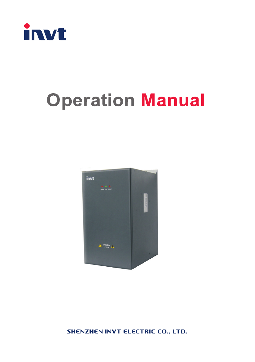
DBU100H
Dynamic Braking Unit
Page 2

Operational manual for dynamic braking unit
Content
1 Safety Precautions .............................................................................................................. 1
1.1 Safety definition ........................................................................................................ 1
1.2 Warning symbols ...................................................................................................... 1
1.3 Safety guidelines ...................................................................................................... 1
2 Inspection ............................................................................................................................ 4
2.1 Unpacking inspection ............................................................................................... 4
2.2 Environment ............................................................................................................. 4
2.3 Installation confirmation ............................................................................................ 5
3 Installation Guidelines .......................................................................................................... 6
3.1 Installation environment ............................................................................................ 6
3.2 Installation direction .................................................................................................. 7
3.3 Installation mode ...................................................................................................... 8
3.4 External dimensions ................................................................................................. 8
4 Product name, model definition and usage ........................................................................ 10
5 Installation of the dynamic braking unit and parameters setting .......................................... 11
5.1 Wiring diagram ....................................................................................................... 11
5.2 Terminals of the main circuit ................................................................................... 11
5.3 Main control terminal of the braking unit ................................................................. 12
5.4 Adjustment ............................................................................................................. 12
5.5 Voltage selection setting ......................................................................................... 12
6 Parallel running.................................................................................................................. 14
7 Fault analysis and the solution ........................................................................................... 15
8 Selection ........................................................................................................................... 16
8.1 Guidelines of braking voltage selection ................................................................... 16
8.2 Calculation of the braking resistor and the braking current ...................................... 16
8.3 Calculation and selection of the braking resistor ..................................................... 16
8.4 Usage standard and selection reference of the input voltage degree for adaptation
DBU (220V) .................................................................................................................. 17
8.5 Usage standard and selection reference of the input voltage degree for adaptation
DBU (380V) .................................................................................................................. 17
8.6 Usage standard and selection reference of the input voltage degree for adaptation
DBU (660V) .................................................................................................................. 18
8.7 Selection of the braking resistors: ........................................................................... 19
9 Maintenance and hardware diagnostics ............................................................................. 21
9.1 Maintenance intervals ............................................................................................. 21
9.2 Cooling fan ............................................................................................................. 24
9.3 Power cable ........................................................................................................... 24
-1-
Page 3
Operational manual for dynamic braking unit
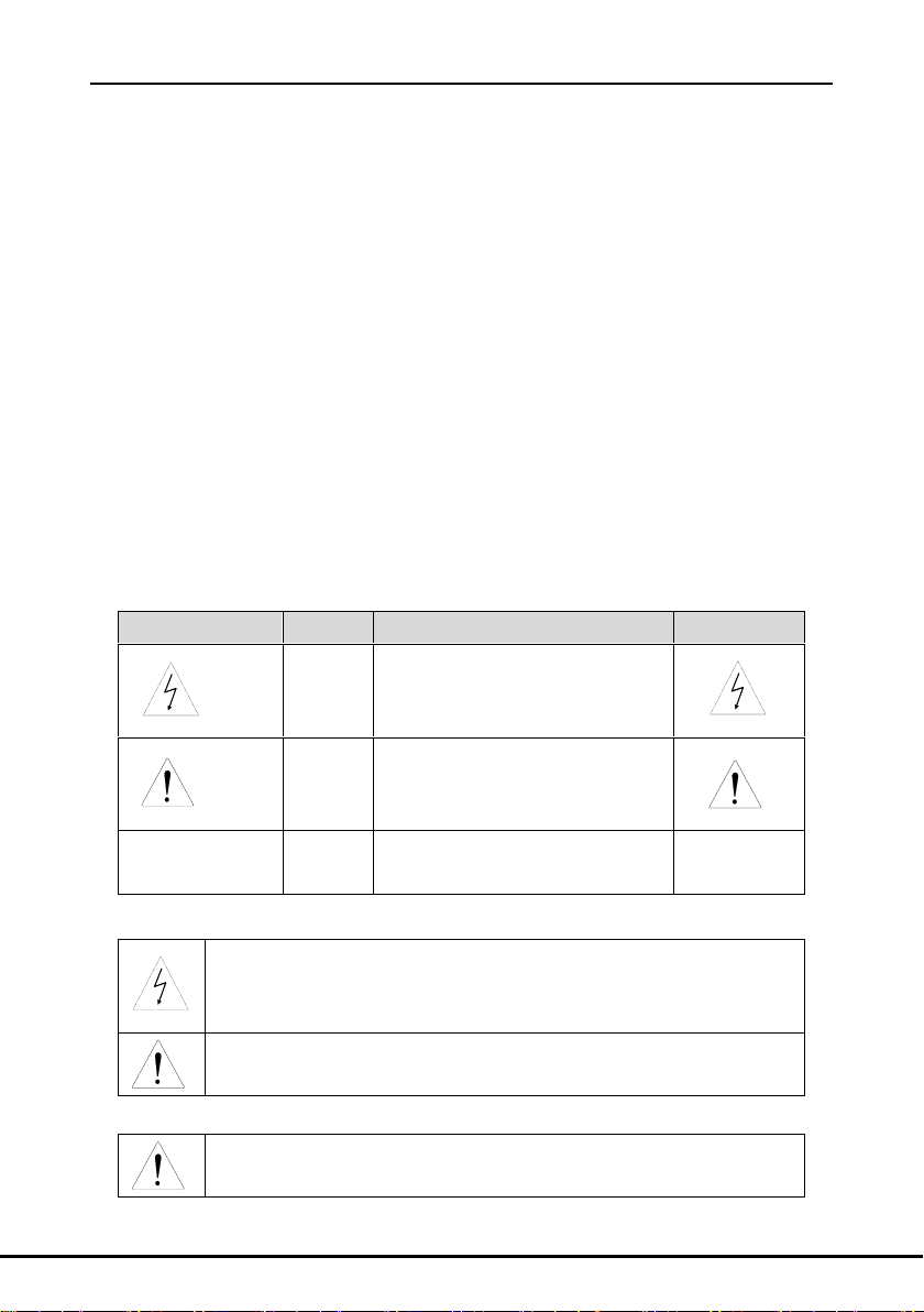
Danger:
Serious physical injury or even death may occur if not follow
relevant requirements
Warning:
Physical injury or damage to the devices may occur if not
follow relevant requirements
Note:
Physical hurt may occur if not follow relevant requirements
Qualified
electricians:
People working on the device should take part in professional
electrical and safety training, receive the certification and be
familiar with all steps and requirements of installing,
commissioning, operating and maintaining the device to avoid
any emergency.
Symbols
Name
Instruction
Abbreviation
Danger
Danger
Serious physical injury or even
death may occur if not follow the
relative requirements
Warning
Warning
Physical injury or damage to the
devices may occur if not follow the
relative requirements
Note
Note
Physical hurt may occur if not
follow the relative requirements
Note
Only qualified electricians are allowed to operate.
Do not carry out any wiring and inspection or changing components
when the power supply is applied.
Do not refit unauthorizedly; otherwise fire, electric shock or other injury
may occur.
Please install the braking units and braking resistors on fire-retardant
material and keep them away from combustible materials.
1 Safety Precautions
1.1 Safety definition
1.2 Warning symbols
Warnings caution you about conditions which can result in serious injury or death and/or
damage to the equipment, and advice on how to avoid the danger. Following warning symbols
are used in this manual:
1.3 Safety guidelines
1.3.1 Delivery and installation
-1-
Page 4
Operational manual for dynamic braking unit
Do not use any braking unit and braking resistor with loss and damaged
components.
High voltage DC current is present after connecting braking unit. Do not
touch the braking unit, internal component and PCB with hands;
otherwise the electric shock may occur.
Disconnect all power supplies applied before the terminal wiring and
wait.
Only qualified electricians are allowed to operate on the dynamic
braking unit.
Check the wiring before the running.
Do not touch the terminal of the control board during powering on.
Check the master details and voltage degree before running.
Do adjust and check the dynamic braking unit only after the POWER
LED is totally off and the voltage between (+) and (-) is 0.
Do not touch any internal components when the dynamic braking
unit is working.
The braking unit is the accessory device of the inverter. Please use it
with caution because the damage to the inverter and the dynamic
braking unit may occur.
Our company reserves the right to take the responsibility for the
Note:
Select appropriate moving and installing tools to ensure a safe and normal running of the
dynamic braking unit and avoid physical injury or death. For physical safety, the erector
should take some mechanical protective measurements, such as wearing exposure
shoes and working uniforms.
Ensure to avoid physical shock or vibration during delivery and installation.
Do not hold its front cover only. The cover may fall off.
Install away from children and other public places.
The dynamic braking unit cannot meet the requirements of low voltage protection in
IEC61800-5-1 if the sea level of installation site is above 2000m.
Please use the DBU on appropriate condition (See chapter Installation Environment).
Don't allow screws, cables and other conductive items to fall inside the DBU.
Fasten the screws while wiring, otherwise the loose wiring may cause fire or current
leakage.
1.3.2 Commission and running
-2-
Page 5
Operational manual for dynamic braking unit
DBU (no matter it is relative to the braking unit or not). Please install
the safety fuses special for the semiconductors.
Only qualified electricians are allowed to perform the maintenance,
inspection, and components replacement of the DBU.
Disconnect all power supplies to the DBU before the terminal wiring.
Wait for at least the time designated on the DBU after disconnection.
Take measures to avoid screws, cables and other conductive
matters to fall into the DBU during maintenance and component
replacement.
There are heavy metals in the dynamic braking unit. Deal with it as
industrial effluent.
When the life cycle ends, the product should enter the recycling system.
Dispose of it separately at an appropriate collection point instead of
placing it in the normal waste stream.
Note:
Do not switch on or off the input power supply of the dynamic braking unit frequently.
Ensure correct setting of the braking units and resistors.
Do not carry out any voltage test on DBU; otherwise damage to the main circuit of the
semiconductor components may occur.
If multiple DBU are installed in a cabiner for paralle application, please install a fan or
other cooling devices.
DBU needs temperature and other protections. It is necessary to isolate the device if fault
occurs to the device and cause heating. If not isolate, our company reserves the right to
the accident.
1.3.3 Maintenance and replacement of components
Note:
Please select proper torque to tighten screws.
Keep the dynamic braking unit, parts and components away from combustible materials
during maintenance and component replacement.
Do not carry out any isolation and voltage test on the dynamic braking unit and do not
measure the control circuit of the dynamic braking unit by megameter.
Carry out a sound anti-electrostatic protection to the dynamic braking unit and its internal
components during maintenance and component replacement.
1.3.4 Scrap treatment
-3-
Page 6

Operational manual for dynamic braking unit
1. Check that there are no damage and humidification to the package. If not, please
contact with local agents or INVT offices.
2. Check the information on the type designation label on the outside of the package
to verify that the drive is of the correct type. If not, please contact with local dealers or
INVT offices.
3. Check that there are no signs of water in the package and no signs of damage or
breach to the DBU. If not, please contact with local dealers or INVT offices.
4. Check the information on the type designation label on the outside of the package
to verify that the name plate is of the correct type. If not, please contact with local
dealers or INVT offices.
1. Check that the ambient temperature of the DBU is below 40℃. If exceeds, derate
3% for every additional 1℃. Additionally, the DBU can not be used if the ambient
temperature is above 50℃.
Note: for the cabinet DBU, the ambient temperature means the air temperature inside
the cabinet.
2. Check that the ambient temperature of the DBU in actual usage is above -10℃. If
not, add heating facilities.
Note: for the cabinet DBU, the ambient temperature means the air temperature inside
the cabinet.
3. Check that the altitude of the actual usage site is below 1000m. If exceeds,
derate1% for every additional 100m.
4. Check that the humidity of the actual usage site is below 90% and condensation is
not allowed. If not, add additional protection the DBU.
5. Check that the actual usage site is away from direct sunlight and foreign objects
can not enter the DBU. If not, add additional protective measures.
6. Check that there is no conductive dust or flammable gas in the actual usage site. If
not, add additional protection to the DBU.
2 Inspection
2.1 Unpacking inspection
Check as followings after receiving products:
2.2 Environment
Check as followings before the actual installation and usage:
-4-
Page 7

2.3 Installation confirmation
1. Check that the load range of the input and output cables meet the need of actual
load.
2. Check that the accessories of the DBU are correctly and properly installed. The
installation cables should meet the needs of every component (including reactors,
input filters, output reactors, output filters, DC reactors, braking units and braking
resistors).
3. Check that the DBU is installed on non-flammable materials and the calorific
accessories (reactors and brake resistors) are away from flammable materials.
4. Check that all control cables and power cables are run separately and the routation
complies with EMC requirement.
5. Check that all grounding systems are properly grounded according to the
requirements of the DBU.
6. Check that the free space during installation is sufficient according to the
instructions in user’s manual.
7. Check that the external connection terminals are tightly fastened and the torque is
appropriate.
8. Check that there are no screws, cables and other conductive items left in the DBU.
If not, get them out.
Check as followings after the installation:
Operational manual for dynamic braking unit
-5-
Page 8
Operational manual for dynamic braking unit
Only qualified electricians are allowed to carry out what described in this
chapter. Please operate as the instructions in Safety Precautions.
Ignoring these may cause physical injury or death or damage to the
devices.
Ensure the power supply of the dynamic braking unit is disconnected
during the operation. Wait for at least the time designated until the
POWER indicator is off after the disconnection if the power supply is
applied. It is recommended to use the multimeter to monitor that the DC
bus voltage of the drive is under 36V.
The installation and design of the dynamic braking unit should be
complied with the requirement of the local laws and regulations in the
installation site. If the installation infringes the requirement, our company
will exempt from any responsibility. Additionally, if users do not comply
with the suggestion, some damage beyond the assured maintenance
range may occur.
Environment
Conditions
Installation site
Indoor
Environment
temperature
-10~+50℃
If the ambient temperature of the dynamic braking unit is above
40℃, derate 3% for every additional 1℃.
It is not recommended to use the dynamic braking unit if the
ambient temperature is above 50℃.
In order to improve the reliability of the device, do not use the
dynamic braking unit if the ambient temperature changes
frequently.
Please provide cooling fan or air conditioner to control the
internal ambient temperature below the required one if the
dynamic braking unit is used in a close space such as in the
control cabinet.
3 Installation Guidelines
3.1 Installation environment
The installation environment is the safeguard for a full performance and long-term stable
functions of the DBU. Check the installation environment as followings:
-6-
Page 9

Operational manual for dynamic braking unit
Environment
Conditions
When the temperature is too low, if the dynamic braking unit
needs to restart to run after a long stop, it is necessary to
provide an external heating device to increase the internal
temperature, otherwise damage to the devices may occur.
Humidity
RH≤90%
No condensation is allowed.
The maximum relative humility should be equal to or less than
60% in corrosive air.
Storage
temperature
-30~+60℃
Running
environment
condition
The installation site of the DBU should:
keep away from the electromagnetic radiation source;
keep away from contaminative air, such as corrosive gas, oil
mist and flammable gas;
ensure foreign objects, such as metal power, dust, oil, water
can not enter into the DBU(do not install the DBU on the
flammable materials such as wood);
keep away from direct sunlight, oil mist, steam and vibration
environment.
Altitude
Below 1000m
If the sea level is above 1000m, please derate 1% for every
additional 100m.
Vibration
≤ 5.8m/s2(0.6g)
Installation
direction
The DBU should be installed on an upright position to ensure
sufficient cooling effect.
Note:
DBU100H series should be installed in a clean and ventilated environment according to
enclosure classification.
Cooling air must be clean, free from corrosive materials and electrically conductive
dust.
3.2 Installation direction
DBU100H must be installed in an upright position.
-7-
Page 10
Operational manual for dynamic braking unit
7
7
H
L1
L W
8
3.3 Installation mode
DBU100H can be installed in wall (for all frame sizes)
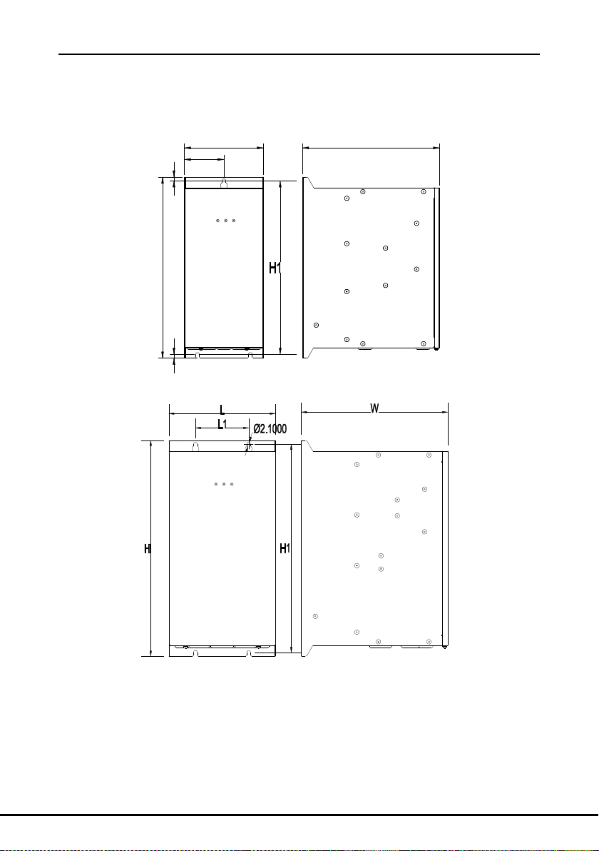
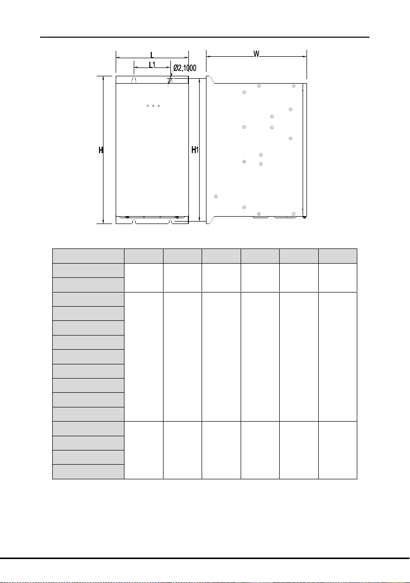
3.4 External dimensions
Figure 1 Dimensions of 60A DBU
Figure 2 Dimensions of 110A-220A DBU
-8-
Page 11
Operational manual for dynamic braking unit
Model
W(mm)
W1(mm)
W2(mm)
D(mm)
H (mm)
H1(mm)
DBU100H-060-2
130
65
65
163
260
246
DBU100H-060-4
DBU100H-110-2
150
75
100
260
340
326
DBU100H-110-4
DBU100H-110-6
DBU100H-160-2
DBU100H-160-4
DBU100H-160-6
DBU100H-220-2
DBU100H-220-4
DBU100H-220-6
DBU100H-320-4
200
100
100
275
405
391
DBU100H-320-6
DBU100H-400-4
DBU100H-400-6
Figure 3 Dimensions of 320A-400A DBU
-9-
Page 12
Operational manual for dynamic braking unit
Field
identification
Detailed description of the sign
A
DBU: Dynamic braking unit
B
1: Technical version
C
00: Spare code
D
L: Light load type, this can be defaulted.
H: Heavy load type
E
Allowable Max. braking current, the unit is A
F
2: Applied on AC 3PH 220V(-15%)~240V(+10%) and the Max. input
voltage DC450V
4: Applied on AC 3PH 380V(-15%)~440V(+10%) and the Max. input
voltage DC900V
6: Applied on AC 3PH 520V(-15%)~690V(+10%) and the Max. input
voltage DC1300V
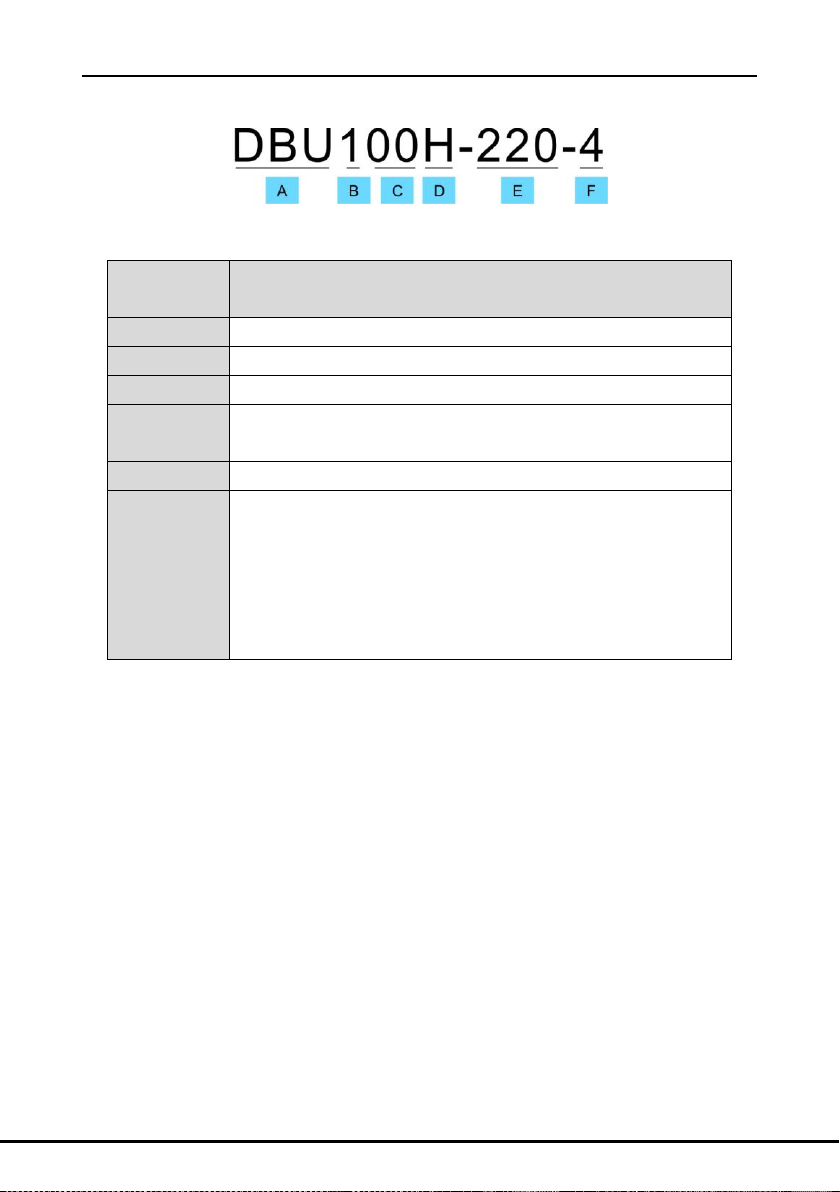
4 Product name, model definition and usage
Instruction:
Table 3 Product model instruction
DBU100H series dynamic braking units are the high-performance and heavy-load dynamic
braking units promoted by our company, which can brakes at the rated braking current to meet
the application need in the situation of big inertia, crash deceleration and stop. When the DBU
brakes, momentum will be converted into electric energy because of big inertia, and then the
DC bus voltage will increase. The braking unit can consume the regenerative electric energy to
ensure normal work of the DBU; otherwise the DBU will carry our overvoltage protection and
work abnormally.
The braking unit can be used in the situation of big inertia and crash-stop. Such as elevators,
textile machines, paper machinery, centrifuges, washing machines, wire drawing machines,
winder, the proportion of linkage systems, crane and mining, and lifting system.
-10-
Page 13
Operational manual for dynamic braking unit
Wrong wiring of the main circuit may cause damage to the DBU and the
braking unit.
Do not touch the terminals of the control board when the machine is
powering on.
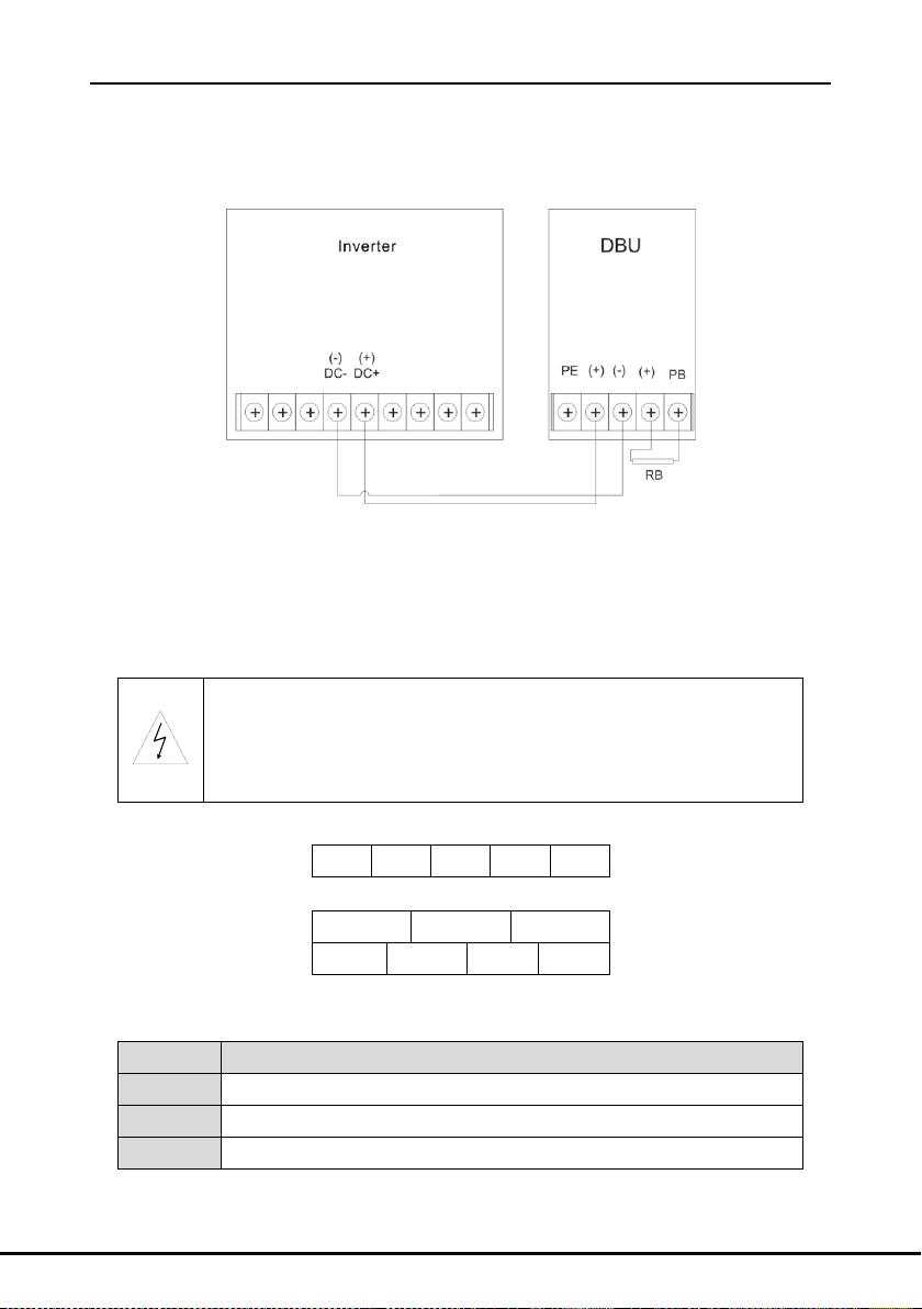
PE
(+)
(-)
(+)
PB
(+)
(+)
(+)
PE
(-)
(-)
PB
Sign
Function
(+),(-)
Input terminal of the DC bus
(+),PB
External braking resistor terminal
PE
Grounding terminal. Each machine should be grounded.
5 Installation of the dynamic braking unit and parameters
setting
5.1 Wiring diagram
Figure 4 Wiring diagram of the main circuit between the dynamic braking unit and the DBU
Note:
DC+ and DC- are the “+”“-” of the internal DC bus in the DBU. DC+ is the positive pole and
DC- is the negative pole.
5.2 Terminals of the main circuit
Figure 5 Terminals of main circuit 60A-220A
Figure 6 Terminals of main circuit 320A~400A
Functions description:
-11-
Page 14
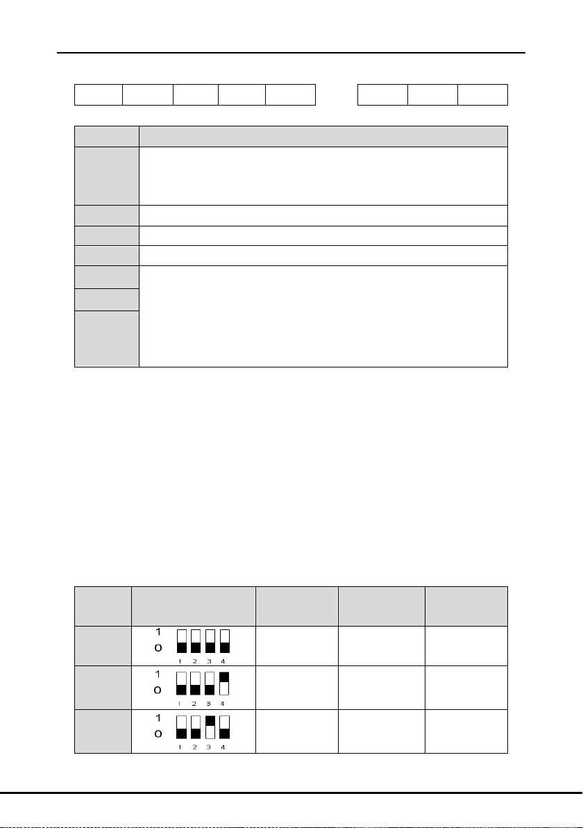
Operational manual for dynamic braking unit
EFI
COM
PI
PO
COM ROA
ROB
ROC
Sign
Function
EFI
Input terminal of the external fault. EFI-COM is defaulted to be short
circuited in factory. When the external fault occurs, it will be switched off
and the braking unit outputs fault signal.
PI
Slave parallel input terminals of the braking unit
PO
Master parallel output terminals of the braking unit
COM
Common terminal of EFI, PI and PO
ROA
1. Fault output terminal. When fault occurs to the braking unit, the fault
relay will output fault report signal.
2.ROA NO, ROB NC, ROC is the common terminal
1. Contact Rating: 3A/AC250V, 1A/DC30V
2. Do not use it as the high frequency switch output (with cautions)
ROB
ROC
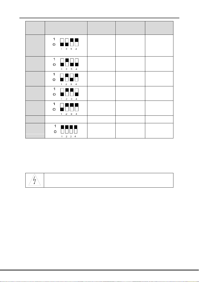
Serial
No.
S1 selection
220V system
(V)
380V system
(V)
690V system
(V)
0
350
640
1040
1 360
660
1060
2 370
680
1080
5.3 Main control terminal of the braking unit
Functions description:
When there is only one braking unit, please connect the DBU, braking unit and braking resistor
according to figure 4. It will work after setting the voltage degree and the braking threshold.
5.4 Adjustment
The braking unit and the braking resistor need not to be adjusted. In special, do not adjust the
braking unit on the situation of “voltage selection setting”.
5.5 Voltage selection setting
The setting of braking threshold: set the voltage selection of the braking unit according to the
input voltage of the DBU. The voltage selection can only performed when disconnecting the
power supply. Below is the relationship between the voltage selection and the original braking
voltage:
-12-
Page 15
Operational manual for dynamic braking unit
Serial
No.
S1 selection
220V system
(V)
380V system
(V)
690V system
(V)
3
(Factory reserved)
380
700
1100
4 390
720
1120
5 400
740
1140
6 410
760
1160
7 420
780
1180
8
1000~1110
Reserved
Reserved
Reserved
9 Slave mode
Slave mode
Slave mode
Do not operate during powering on. Do not adjust the setting when the
POWER LED is not totally off (the voltage is present between (+) and (-)).
Note:
If the grid voltage is above more than 20% of the normal supply, please set bigger
braking voltage.
Please ensure the allowable original braking voltage of the DBU comply with this
setting.
-13-
Page 16
Operational manual for dynamic braking unit
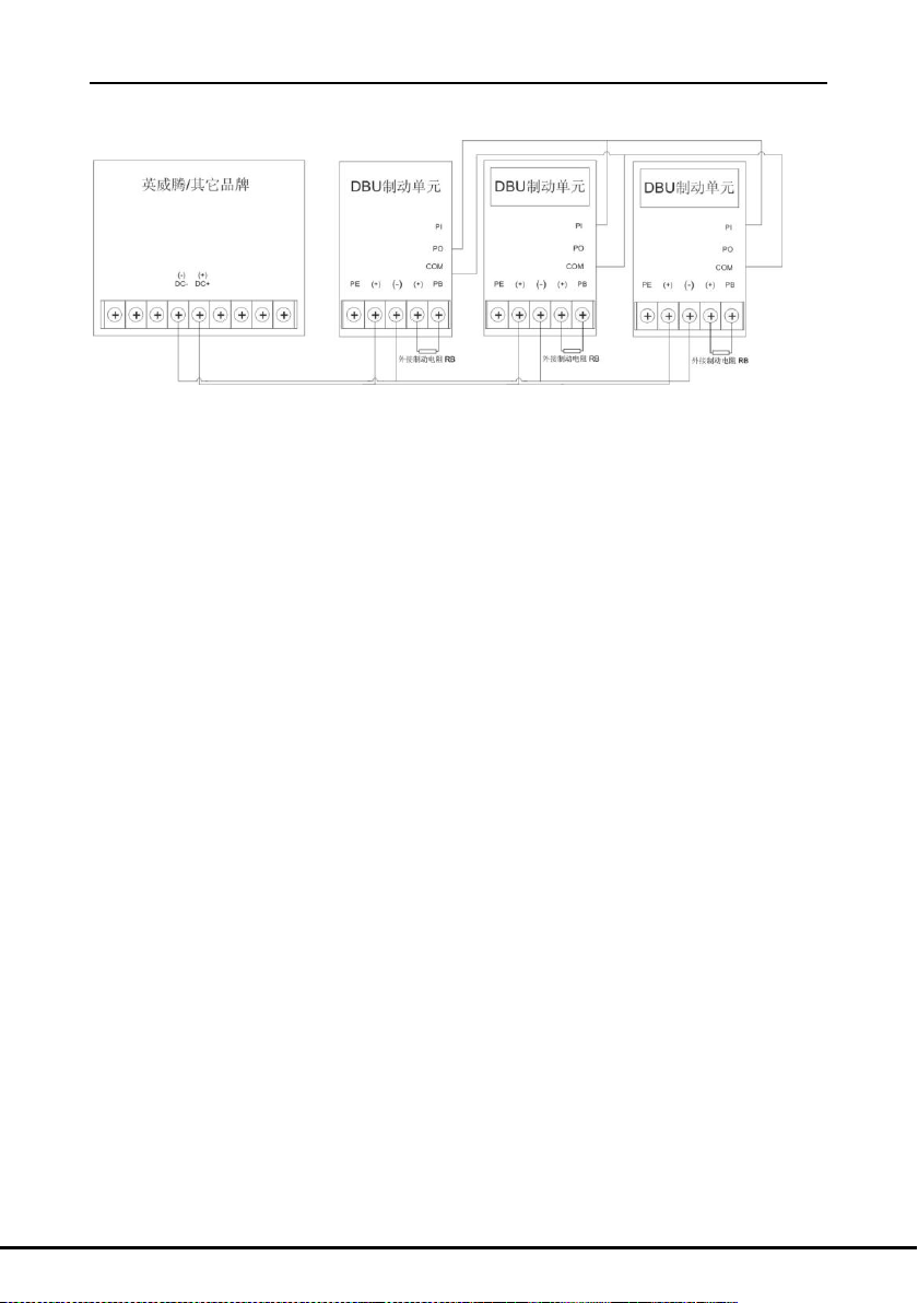
6 Parallel running
Figure 7 Wiring diagram between the parallel running braking units and the DBU
Please connect the DBU, multiple braking units and the braking resistor according to figure 7.
Wiring of the control terminals: when parallel braking units are put into use, the first one is the
master and the others are the slaves. The parameters setting of the slave are referred to the
section 9 of “braking threshold” and the braking rate of the master and the slave need to be
kept the same. The PO and COM terminal of the first braking unit is connected to the PI and
COM terminal of the second braking unit and the PI and COM terminal of the third braking unit
and so forth, the running of the whole parallel braking unit system can be monitored.
-14-
Page 17
Operational manual for dynamic braking unit
Serial
No.
Fault state
Reasons
Solutions
1
Serious
heat-releasing of
the braking resistor
during the braking
The power of the braking resistor
is too low.
Change a braking
resistor with bigger
power.
2
Serious
heat-releasing of
the braking resistor
when not braking
IGBT damage
Change the
braking unit
The voltage selection of the
braking unit is not correct.
Reset
Braking unit fault
Change the
braking unit
3
OU of the DBU
Insufficient braking capacity of the
braking resistor
Recheck the
braking condition
Wrong wiring
Check and correct
The voltage selection of the
braking unit is not correct.
Reset
Braking unit fault
Change the
braking unit
4
Output signal of
the fault relay
Valid external fault input
Recheck the
running condition
Short circuit of the braking resistor
Change the
braking resistor
The temperature of IGBT is over
85℃
Non-isolated circuit is applied in the control circuit of the braking unit.
Disconnect the wiring between (+) and (-) and ensure there is no voltage
during the operation and checking.
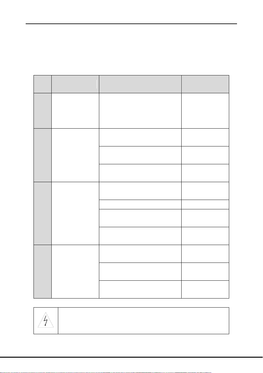
7 Fault analysis and the solution
The fault can be indicated through LEDs. When the FAULT LED is on, it means the dynamic
braking unit is abnormal. Check the faults one by one according to the information in the below
table. Find the possible reasons and the solutions. If not, please contact with the local INVT
office.
Note: when the external grid voltage is too high, please set bigger voltage.
-15-
Page 18

Operational manual for dynamic braking unit
8 Selection
8.1 Guidelines of braking voltage selection
The setting of the braking voltage is low enough to make the DBU works around the rated
voltage and ensure a safe running. Select high braking voltage can avoid misaction of the
braking unit, but too high voltage has impact on the long-term running safety.
8.2 Calculation of the braking resistor and the braking current
(at 100% of the braking torque)
Braking current is the DC current running through the braking unit and the braking resistor
during braking.
Calculating at the standard AC motor of 380V:
P―――― Rated power of the motor (kW)
V―――― DC operating point of the braking unit, usually it is 700V
I―――― Braking current (A)
―――― Conversion efficiency of the mechanical energy during feedback, usually it is 1.0
Calculation basis: the braking resistor needs to absorb all the regenerative electric energy of
the motor.
Absorbed power of the braking resistor (V*I)=The regenerative electric energy of the motor
(W)=1000*P*
8.3 Calculation and selection of the braking resistor
(at 100% of the braking torque)
The braking resistor reflects the braking torque in the system. If the braking torque is too small,
the DBU will carry out overvoltage protection.
Calculating at the standard AC motor of 380V:
P―――― Rated power of the motor (kW)
PR―――― Rated consumed power of the braking resistor (kW)
V――――DC operating point of the braking unit, usually it is 700V
R―――― Equivalent resistance of the braking resistor (Ω)
――――Conversion efficiency of the mechanical energy during feedback, usually it is 1.0
――――Safety coefficient of the power consumption for the braking resistor
Kf――― Braking frequency, the time ratio of the regeneration to the whole working time
Usually, Kf is:
Winding up and winding down Kf=50-60%
Oilfield machines Kf=10-20%
Elevators Kf=10-15%
Centrifuge Kf=5-20%
-16-
=1.4
Page 19
Operational manual for dynamic braking unit
Power
Model
100% of the
adaptation
braking
resistor of
the braking
torque(Ω)
Dissipated
power of the
braking
resistor(kW)
(10% of the
braking)
Dissipated
power of the
braking
resistor(kW)
(50% of the
braking)
Dissipated
power of the
braking
resistor(kW)
(80% of the
braking)
Mini
allowable
braking
resistor(Ω)
15kW
DBU100H-60-2
9.6
2
11
18
6.4
18kW
8.0
3
14
22
22kW
6.5
3
17
26
30kW
DBU100H-110-2
4.8
5
23
36
3.5
37kW
3.9
6
28
44
45kW
DBU100H-160-2
3.2
7
34
54
2.4
55kW
2.6
8
41
66
75kW
DBU100H-220-2
1.9
11
56
90
1.8
90kW
Two
DBU100H-160-2
1.6
7*2
34*2
54*2
2.4*2
110kW
1.3
9*2
43*2
66*2
Crane(the height of lifting is more than 100m) Kf=20-40%
Occasionally braking load Kf=5%
Others Kf=10%
Basis of resistor calculation: the braking resistor needs to absorb all the regenerative electric
energy of the motor.
Absorbed power of the resistor(V*V/R)=The regenerative electric energy of the motor (W)=
1000*P*
Basis of resistor power calculation:
The regenerative electric energy of the motor needs to be absorbed by the resistor and
converted into heat to release.
PR =P* Kf **=P* Kf *1.0*1.4
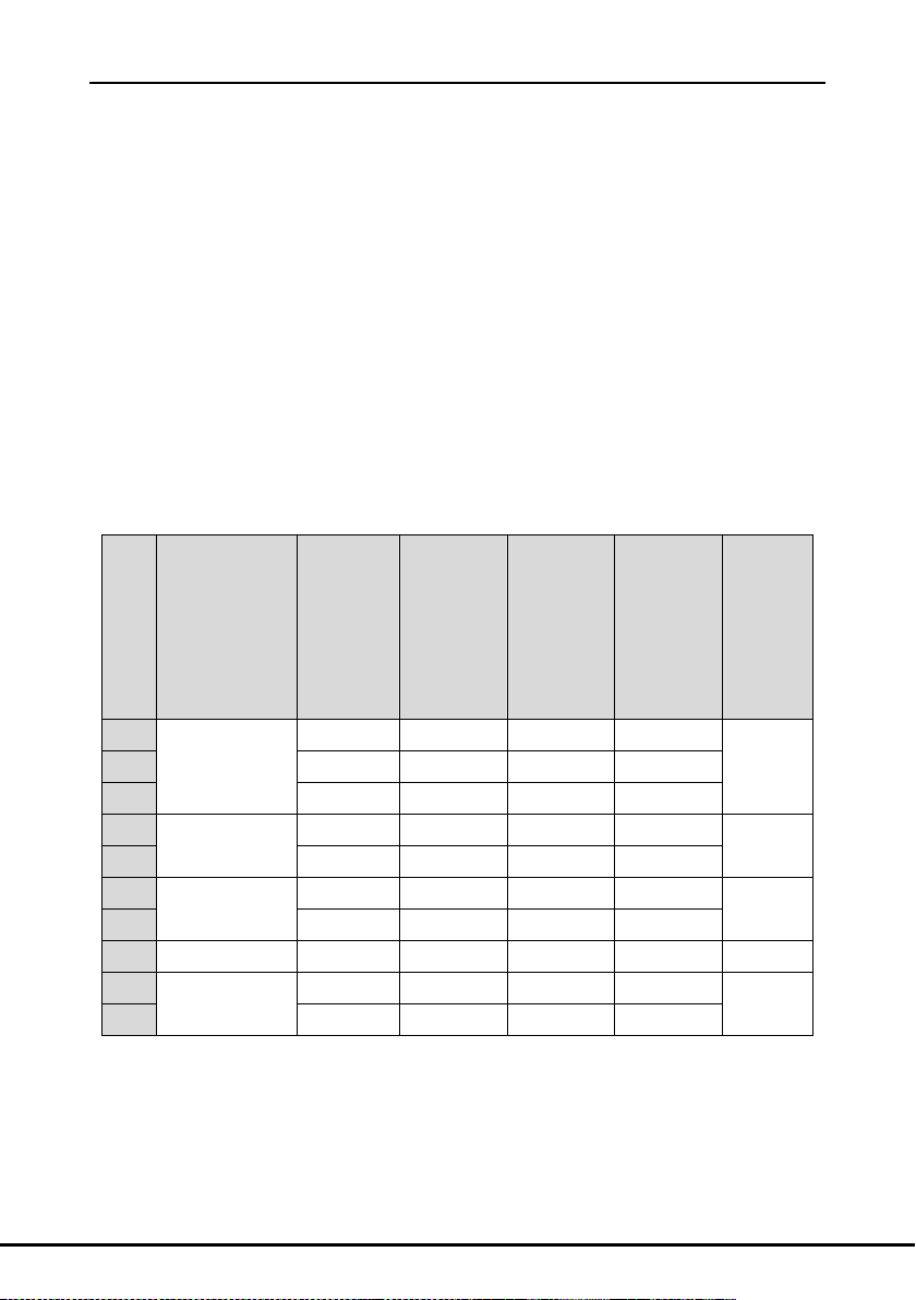
8.4 Usage standard and selection reference of the input voltage degree
for adaptation DBU (220V)
Below is the selection reference when the DC operating point of the braking unit is 380V:
8.5 Usage standard and selection reference of the input voltage degree
for adaptation DBU (380V)
Below is the selection reference when the DC operating point of the braking unit is 700V:
-17-
Page 20
Operational manual for dynamic braking unit
Power
Model
100% of the
adaptation
braking
resistor of
the braking
torque(Ω)
Dissipated
power of the
braking
resistor(kW)
(10% of the
braking)
Dissipated
power of the
braking
resistor(kW)
(50% of the
braking)
Dissipated
power of the
braking
resistor(kW)
(80% of the
braking)
Mini
allowable
braking
resistor(Ω)
37kW
DBU100H-060-4
13.2 6 28
44
11.7
45kW
DBU100H-110-4
10.9 7 34
54
6.4
55kW
8.9 8 41
66
75kW
6.5
11
56
90
90kW
DBU100H-160-4
5.4
14
68
108
4.4
110kW
4.5
17
83
132
132kW
DBU100H-220-4
3.7
20
99
158
3.2
160kW
DBU100H-320-4
3.1
24
120
192
2.2
200kW
2.5
30
150
240
220kW
DBU100H-400-4
2.2
33
165
264
1.8
250kW
2.0
38
188
300
280kW
Two
DBU100H-320-4
3.6*2
21*2
105*2
168*2
2.2*2
315kW
3.2*2
24*2
118*2
189*2
350kW
2.8*2
27*2
132*2
210*2
400kW
2.4*2
30*2
150*2
240*2
500kW
Two
DBU100H-400-4
2*2
38*2
186*2
300*2
1.8*2
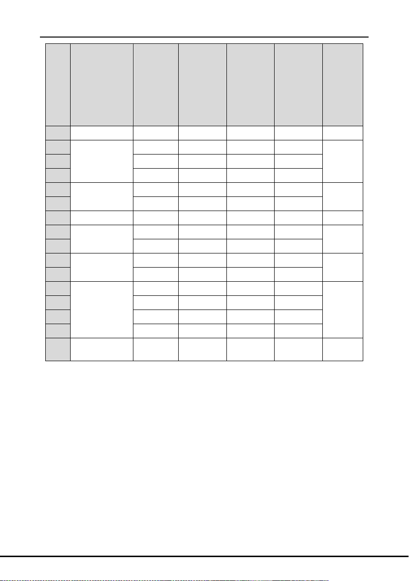
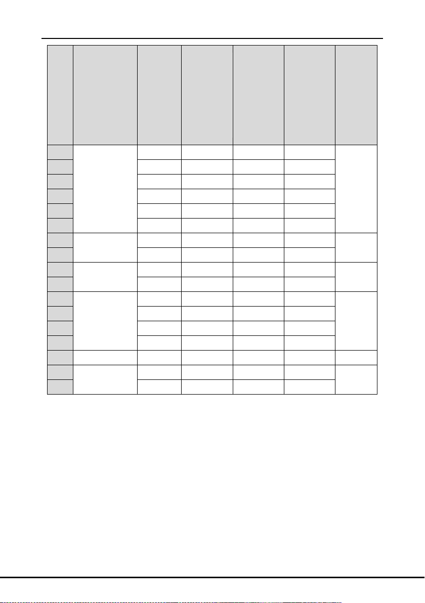
8.6 Usage standard and selection reference of the input voltage degree
for adaptation DBU (660V)
Below is the selection reference when the DC operating point of the braking unit is 1100V:
-18-
Page 21
Operational manual for dynamic braking unit
Power
Model
100% of
the
adaptation
braking
resistor of
the braking
torque(Ω)
Dissipated
power of the
braking
resistor(kW)
(10% of the
braking)
Dissipated
power of the
braking
resistor(kW)
(50% of the
braking)
Dissipated
power of the
braking
resistor(kW)
(80% of the
braking)
Mini
allowable
braking
resistor(Ω)
37kW
DBU100H-110-6
32.7
6
28
44
10.0
45kW
26.9
7
34
54
55kW
22.0
8
41
66
75kW
16.1
11
56
90
90kW
13.4
14
68
108
110kW
11.0
17
83
132
132kW
DBU100H-160-6
9.2
20
99
158
6.9
160kW
7.6
24
120
192
200kW
DBU100H-220-6
6.1
30
150
240
5.0
220kW
5.5
33
165
264
250kW
DBU100H-320-6
4.8
38
188
300
3.4
280kW
4.3
42
210
336
315kW
3.8
47
236
378
350kW
3.5
53
263
420
400kW
DBU100H-400-6
3.0
60
300
480
2.8
500kW
Two
DBU100H-320-6
4.8*2
38*2
186*2
300*2
5.0*2
560kW
4.4*2
42*2
210*2
336*2
8.7 Selection of the braking resistors:
It is recommended to apply non-inductive resistance to reduce the inductance.
The protective devices for auto-partitioning during overheating are necessary.
The grounding fault is prohibited; otherwise the damage to the device and DBU may
The capacity of the braking resistor is the reference value and it can be modified
Our company also has cement resistor and big power printing resistor and non inductive
occur.
according to the inertial loads, braking frequency, braking voltage threshold. Please
consult with our company for more information.
-19-
Page 22

Operational manual for dynamic braking unit
resistance to sell.
Note:
Parallel braking unit can enlarge the braking capacity.
The braking capacity of 2 parallel braking units is two times of one braking unit. For example
DBU100H-220-4=DBU100H-110-4*2。
-20-
Page 23

Operational manual for dynamic braking unit
Checking part
Checking item
Checking
method
Criterion
Ambient environment
Check the ambient
temperature, humidity
and vibration and
ensure there is no dust,
gas, oil fog and water
drop.
Visual
examination
and instrument
test
Conforming to
the manual
Ensure there are no
tools or other foreign or
dangerous objects
Visual
examination
There are no
tools or
dangerous
objects.
Voltage
Ensure the main circuit
and control circuit are
normal.
Measurement
by millimeter
Conforming to
the manual
Keypad
Ensure the display is
clear enough
Visual
examination
The characters
are displayed
normally.
Ensure the characters
are displayed totally
Visual
examination
Conforming to
the manual
Main
circuit
For public use
Ensure the screws are
tightened securely.
Tighten up
NA
Ensure there is no
distortion, crackles,
damage or
color-changing caused
by overheating and
aging to the machine
and insulator.
Visual
examination
NA
9 Maintenance and hardware diagnostics
9.1 Maintenance intervals
If installed in an appropriate environment, the dynamic braking unit requires very little
maintenance. The table lists the routine maintenance intervals recommended by INVT.
-21-
Page 24

Operational manual for dynamic braking unit
Checking part
Checking item
Checking
method
Criterion
Ensure there is no dust
and dirtiness
Visual
examination
NA
Note: if the
color of the
copper blocks
change, it does
not mean that
there is
something
wrong with the
features.
The lead of the
conductors
Ensure that there is no
distortion or
color-changing of the
conductors caused by
overheating.
Visual
examination
NA
Ensure that there are
no crackles or
color-changing of the
protective layers.
Visual
examination
NA
Terminals seat
Ensure that there is no
damage
Visual
examination
NA
Resistors
Ensure whether there is
replacement and
splitting caused by
overheating.
Smelling and
visual
examination
NA
Ensure that there is no
offline.
Visual
examination or
remove one
ending to
coagulate or
measure with
multimeters
The resistors
are in ±10% of
the standard
value.
Control
PCB and plugs
Ensure there is no
Fasten up
NA
-22-
Page 25

Operational manual for dynamic braking unit
Checking part
Checking item
Checking
method
Criterion
circuit
loose screws and
contactors.
Ensure there is no
smelling and
color-changing.
Smelling and
visual
examination
NA
Ensure there are no
crackles, damage
distortion and rust.
Visual
examination
NA
Ensure there is no
weeping and distortion
to the capacitors.
Visual
examination or
estimate the
usage time
according to the
maintenance
information
NA
Cooling
system
Cooling fan
Estimate whether there
is abnormal noise and
vibration.
Hearing and
Visual
examination or
rotate with hand
Stable rotation
Estimate there is no
losses screw.
Tighten up
NA
Ensure there is no
color-changing caused
by overheating.
Visual
examination or
estimate the
usage time
according to the
maintenance
information
NA
Ventilating duct
Ensure whether there is
stuff or foreign
objection in the cooling
fan, air vent.
Visual
examination
NA
Consult the local INVT Service representative for more details on the maintenance. Visit the
-23-
Page 26
Operational manual for dynamic braking unit
Read and follow the instructions in chapter Safety Precautions.
Ignoring the instructions would cause physical injury or death, or
damage to the equipment.
Read and follow the instructions in chapter Safety Precautions.
Ignoring the instructions may cause physical injury or death, or
damage to the equipment.
official website of INVT: http://www.invt.com.cn and select Services and Support in the front
page to go to online service.
9.2 Cooling fan
The dynamic braking unit’s cooling fan has a minimum life span of 25,000 operating hours. The
actual life span depends on the usage and ambient temperature.
Fan failure can be predicted by the increasing noise from the fan bearings. If the braking unit is
operated in a critical part of a process, fan replacement is recommended once these symptoms
appear. Replacement fans are available from INVT.
9.2.1 Replacing the cooling fan
1. Stop the DBU and disconnect it from the AC power source and wait for at least the time
designated on the DBU.
2. Lever the fan holder off the drive frame with a screwdriver and lift the hinged fan holder
slightly upward from its front edge.
3. Free the fan cable from the clip.
4. Disconnect the fan cable.
5. Remove the fan holder from the hinges.
6. Install the new fan holder including the fan in reverse order.
7. Restore power.
9.3 Power cable
1. Stop the drive and disconnect it from the power line. Wait for at least the time designated on
the braking unit.
2. Check the tightness of the power cable connections.
3. Restore power.
-24-
Page 27
6 600 1- 00 14 3
I
I
201811 ( V1.6)
 Loading...