

InvoTek BlueSwitch User Manual
BlueSwitch User Manual
Thank you for purchasing BlueSwitch! BlueSwitch is a Bluetooth hub
for interfacing to switch accessible devices. BlueSwitch enables the
switch user to connect as many as three external switches to control
up to three Bluetooth devices (cell phones, computers, tablets). The
user has the ability to cycle through the Bluetooth devices and select
the device they want to control. In this way, one set of switches
controls up to three different devices. In addition, the user can choose
to output their switch activations to two relays, enabling the user to
control wired devices such as a nurse call button.
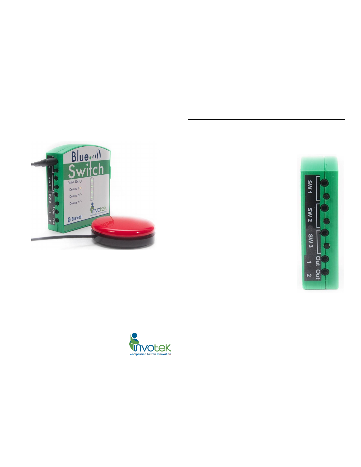
Left Side of BlueSwitch 2
Input Switches
There are three switch jacks and buttons labeled SW1, SW2, and SW3.
This is where you will connect the user’s switches. BlueSwitch accepts
any 3.5mm mono switch output, such as a push-button switch or the
output of a Sip-and-Puff switch. The small
buttons beside each switch jack are there for
convenience to test the functionality of
switches during setup – pressing a button is
identical to activating its associated switch.
All three switch inputs DO NOT provide the
same functionality. It is important to connect
the switches to the correct switch input as
described in the “Switch Configurations”
section, based on the user’s desired
configuration.
Relay Outputs
There are two jacks labeled “Out 1” and “Out
2”. These are relay outputs, allowing the user
to connect wired devices they wish to control
such as a nurse call button. The relays support
a maximum of 1 amp of current and 30 volts
DC. Exceeding these specifications will damage
BlueSwitch.
Figure 1:
Left View
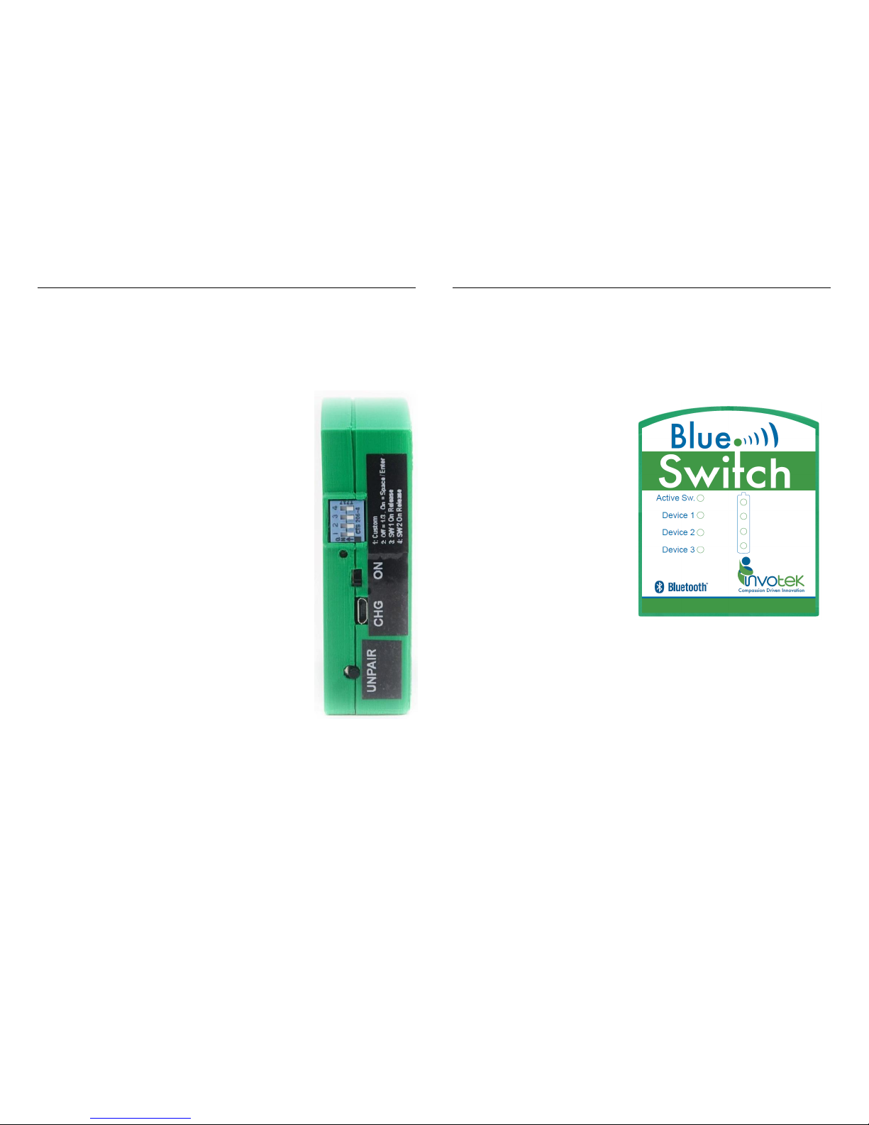
Right Side of BlueSwitch 3
Charging Port
The Micro-B USB jack labeled “CHG” is used to charge the device.
When the provided USB cable is connected and powered, the device
will charge. On the front of BlueSwitch is a battery symbol with four
LEDs that display the current battery status. When the device is
charging, a battery LED will blink.
Unpair Button
This button is used to disconnect BlueSwitch from
all Bluetooth devices. This includes forgetting all
the devices which BlueSwitch attempts to
reconnect to on power up. To do so, hold down
the Unpair button for three seconds until a long
beep is heard.
On/Off Switch
The switch labeled “ON” is the on/off switch. To
turn the device on, slide the switch upward
towards the DIP switches. To turn the device off,
slide the switch downward towards the charging
jack. A green LED above the switch also indicates
when the device is turned on.
DIP Switches
The light-blue DIP switches enable switching
among basic configurations without using the
BlueSwitch Android app. These configurations are
discussed in detail in the section “DIP Switch
Settings”.
Front of BlueSwitch 4
Active Sw. LED
The Active Sw. LED glows green when SW1 is activated, red when SW2
is activated, and orange when SW3 is activated. The Active Sw. LED will
blink orange when attempting to auto-reconnect to previously
connected Bluetooth devices.
Device 1/2/3 LEDs
These LEDs indicate when
Bluetooth devices are
connected to BlueSwitch. Each
LED will glow green when that
device is connected. The
device’s LED glows orange when
it is selected as an output device
for switch activations. If all the
device’s LEDs are green or no
Bluetooth devices are
connected, switch activations
are sent to the relay outputs
instead of to a Bluetooth device.
Battery Symbol
The battery symbol has four LEDs that display the battery power
status. When the device is charging, a battery LED will blink.
Figure 2:
Right View
Figure 3:
Front View
 Loading...