

Page 1
TRINITY PLUS
USER MANUAL
Page 2

Page 3

Table of content
1.Op en-Packa ge guideli nes.. ... ..... ........ ........ ........ ........ ........ ..... ... . .1
1.1Pack age..... ........ ........ ........ ..... ... ..... ........ ........ ........ ........ ... .. .1
2.Sa fety instr uctio ns. ..... ........ ........ ........ ........ ........ ..... ... ..... ... ..... ...1
3.Op erating de termi nat ions. ........ ........ ........ ........ ........ ..... ... .... ......3
4.Ri gging the fi xture... ..... ... ..... ... ..... ........ ........ ........ ........ ........ . .... ..4
4.1 Mo unting.. ........ ........ ........ ..... ... ..... ... ..... ........ ........ ........ ... .. ... ..4
4.2I nstallin g the Clamps ..... ... ..... ... ..... ........ ........ ........ ........ ........ ..... ... ..... ..4
4.3 Po wer supply c onnectio n and cut off. ..... ... ..... ........ ........ ........ ........ .....5
4.4 Po wer Connec tion.... ..... ... ..... ... ..... ........ ........ ........ ........ ........ ........ ..... .6
4.5 DM X-512 conn ectio n/c onnec tion betwe en fixture s.... ... ..... ... ..... ........ .6
Desc ription of t he device. ..... ... ..... ........ ........ ........ ........ ........ ..... ...7
5.
Dime nsion... ........ ........ ..... ... ..... ... ..... ........ ........ ........ ........ ........ .. ..8
6.
Disp lay contro l....... ..... ... ..... ... ..... ........ ........ ........ ........ ........ ..... ....9
7.
Navi gation in th e Menu.... ........ ..... ... ..... ........ ........ ........ ........ ...9
7.1
Disp lay Operat ion..... ..... ... ..... ........ ........ ........ ........ ........ ....... ...9
7.2
Menu M aps..... ........ ........ ........ ..... ... ..... ... ..... ........ ........ ........ ....... 11
7.3
8.DM X protocol ........ ........ ..... ... ..... ... ..... ........ ........ ........ ........ ...... .. 12
9.Ma intance an d cleaning ..... ... ..... ... ..... ........ ........ ........ ........ ..... ... 16
10.E lectric eq uipment sp ecifi cation.. ........ ........ ........ ..... ... ..... . ....... 17
10.1 E lectrica l param ter s.... ........ ........ ........ ........ ........ ..... ... ..... . ..17
Weig ht and dimen sions
10.2
Chan nel Charac teris tic s.... ........ ........ ........ ........ ........ ..... ... ..... ........ ..17
10.3
10.4 M enu Functi on...... ........ ..... ... ..... ... ..... ........ ........ ........ ........ ........ ..... .17
10.5 l ight table ........ ........ ..... ... ..... ... ..... ........ ........ ........ ........ ........ ..... ... ...18
.... ........ ........ ........ ........ ..... ... ..... ... ..... ........ ...17
10.6 C olor wheel ........ ........ ..... ... ..... ........ ........ ........ ........ ........ ........ ..... ... .19
10.7 G obo wheel. ........ ........ ..... ... ..... ... ..... ........ ........ ........ ........ ........ ..... ... 19
11.E lectroni c drawi ng. ..... ... ..... ........ ........ ........ ........ ........ ..... ... ..... ... ..... .....21
.... ........
.... ........
.... ........
.... ........
.... ........
.... ........
.... ........
.... ........
.... ........
.... ........
.... ........
.... ....
.... ........
.... ........
.... ........
.... ........
Page 4

Congratu la tions on choosi ng o ur p ro ducts! Plea se c ar efully read thi s in st ruction man ua l in i ts
entire ty a nd k ee p it well for using refer en ce. Th is m anual contain ed a bo ut the installa ti on and
the relati ve u si ng informat io n of this pr oducts. Ple se r ef ere this manual 's r el ative instr uc ti on
when using thi s eq uipment.
Page 5
1.Open-Package guidelines
This equi pm en t is m ad e of new style,high intensity pla st ic .I t fu ll y sh ow s the modem times lig ht c ha ra c
tic with
teristic wi th b ea ut y st ru tu re . And it is made a cc or d to C E standard. Fully agree wit h th e in te rn at io n
standard of D MX
Wh e n r ece i ve the pr o duc t ,pl e ase be ca r efu l t o t a ke an d p u t ,c h e ck if th e p r odu c t h as dam a ge or not be -
caus e of t ra ns portati on , an d check the f ol lo wing part s:
1.Si gn al c ab le-1P C 2.Sa ft y ca ble-1PC
3.Us er M an va l-1PC 4.Ome ga h ol der-2PC S
5.Po we r ca bl e-1PC 5.Ser vi ce c ard-1PC
512 agree me nt .
teris-
1.1Package
Unpa ck in g th e fixture
1.Op en t he f li ght case co ve
2.Wi th o ne p er son on each s id e, l ift the fix tu re o ut o f the fli gh t ca se .
3.Un lo ck p an a nd tilt bef or e op erating f ix tu re .
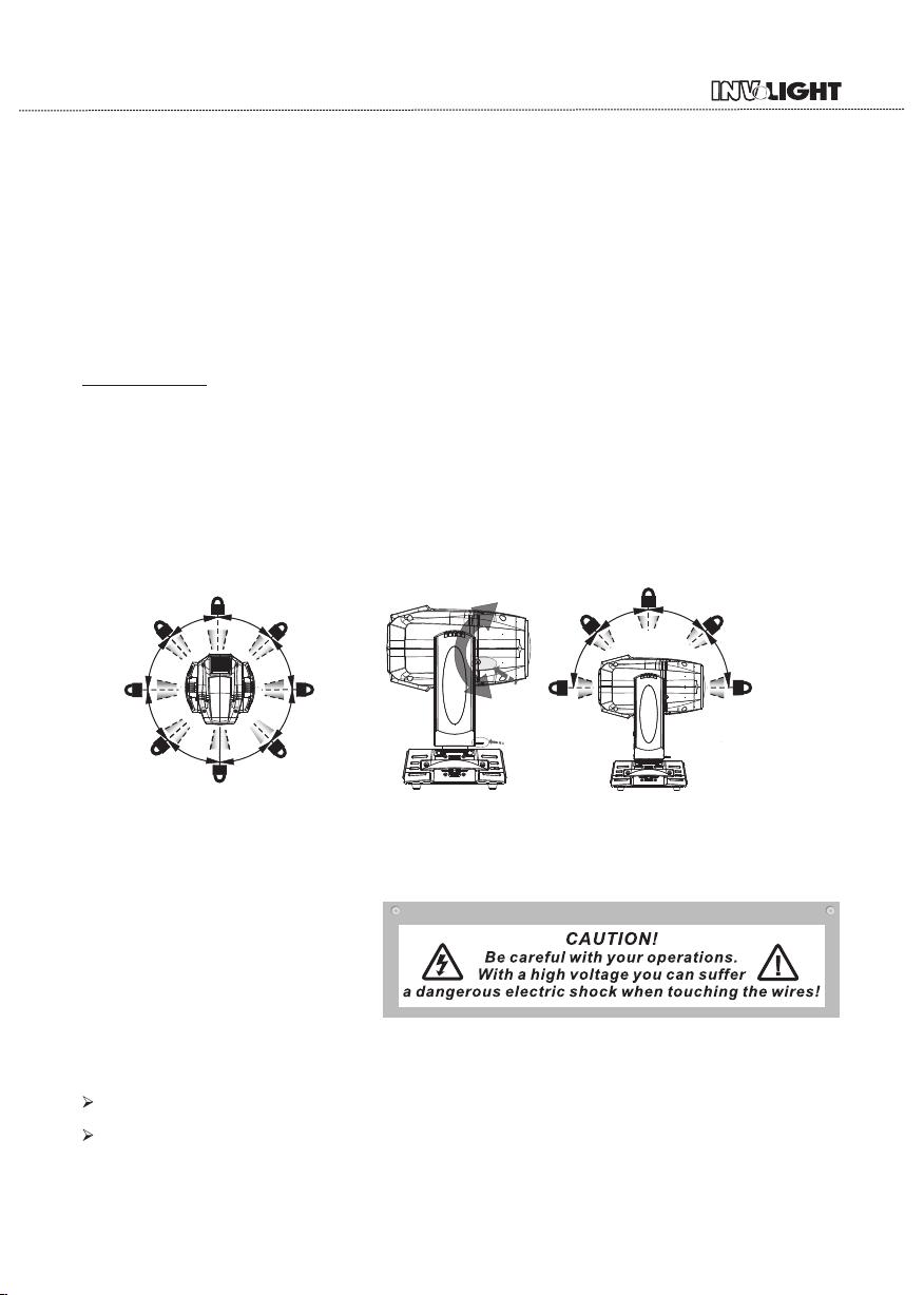
Pack in g th e fi xture
1.Di sc on ne ct the fixt ur e fr om power an d al lo w it t o cool.
2.lo ck a rm s an d h as fig ur e. (
- Fig. 1- 1) (Tilt Me ch an ism Lock an d Re le as e (ever y 45 °) - F ig .1-2)
3.Pl ac e th e fi x ture in the b ot to m of the flig ht c as e, a nd cove r th e ca se w ithout fo rc in g.
ead - Fig. 1 PAN Me chani sm L oc k an d Release ( ev er y 45°)
4
45°
5°
4
45°
°
PAN Me ch ani sm Lock
5°
5
.
4
°
45
°
4
5°
45
°
UNL OCKED
hea d
l
ock
LOC KED
o
l
m
r
A
k
c
4
45
5°
5
°
4
5
°
4
Lev el vert ical tr anspo rtati on lock F ig.1
Fig .1-1
Til t Mec hanis m Lock
Fig .1- 2
2.Safety instructions
Ever y pe rs on i nvolvd wi th i ns tallati on a nd m aintena nc e of t hi s devic e to :
-Be qu al il fi ed
-Fol lo w th e in structi on s of t his manua l.
This device has been shipped with our premises in abs ol utely perfect co ndition.In order to ma intain this co ndition and toensure a safe operation,it is absolutely necessary for the user to fo ll ow t he s af et y in st ru ct io ns
and warning notes written in this manual.
Important:
The m an uf ac tu re r wi ll n ot a cc ep t li ab il it y fo r an y re su lt in g da ma ge s ca us ed b y th e no no bs er va nc e of t hi s
manual or any unauthorized modification to the device.
Please consider that damages caused by manual modifications to the de vice are n ot s ub je ct t o wa rr an ty.
- 1 -
Page 6
Neve r le t th e po wer-cor d co me i nto conta ct w it h ot her cab le s! H an dle the pow er c or d and all con ne ct io ns
with p ar ti cu lar cauti on !
Make s ur e th at t he availa bl e vo ltage is no t hi gh er t han sta te d on t he r earpane l.
A lw ay s plug i n th e power p lu g le as t. Make sue r th at t he p ower- sw it ch i s set to off-posi ti on b efore you c on
ecti on s wi th t hemains w it h pa rticula r ca ut io n!
Make s ur e th at t he power- co rd i s never cri mp ed o r da maged b y sh ar p ed ges.Che ck t he d ecice and t he p ower -c or d fr om time to ti me .
Alway s di sc on nect from t he m ai ns, when th e de vi ce i s not in us e or b ef or e cleanin g it .
Only hand le t he p ow er-cord b y th e pl ug,Neve r pu ll o ut t he plug b y tu gg in g the pow er co rd .
This dev ic e fa ll s under pro te ct ion class I .T he re fore it i s es se nt ial to conn ec t th e ye llow/ gr ee n co nduct or
to ear th .
T he elec tric co nn ec ti on,repa ir s an d servici ng m us t be c arrie d ou t by a q ua lified em pl oy ee.
Do n ot c on ne ct this d ev ic e to a d immer pac k.
Do n ot s wi tc h the fix tu re o n an d off in s hort inte rv al s as this wou ld r ed uc e the lam p’s life .
Do not t ou ch t he d evice’s housi ng b ar e hands dur in g it s op erati on (h ou sing be co me s ho t)!
For re pl ac em ent use lam ps a nd f uses of sam e ty pe a nd r ating o nl y.
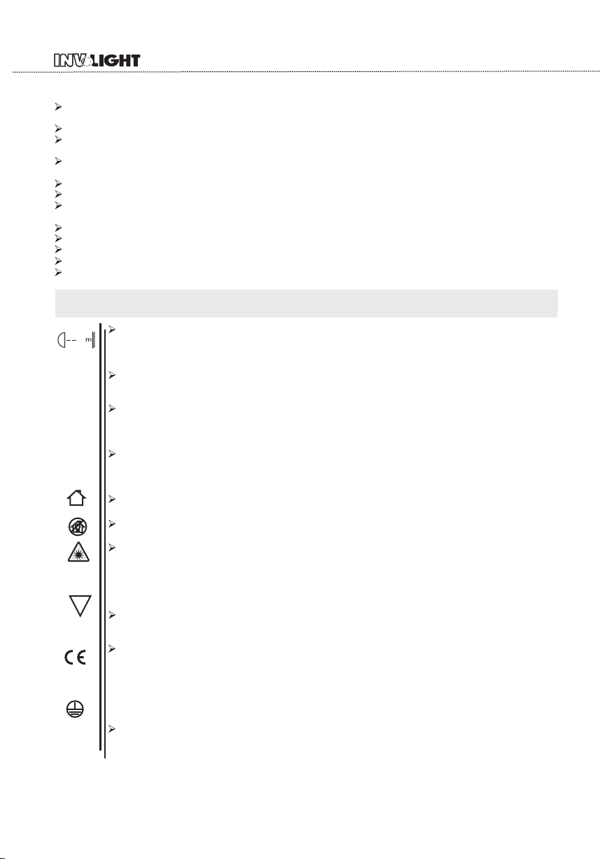
Eye da mage!
Avoi d looki ng dire ctly in to the li ght sou rce(m ea nt es pe cia ll y for e pi lep ti cs)!
Mini mum dis tance o f illum inate d objec ts
12
The pr oj ec to r needs to be p os it ioned so th at t he o bj ects hi t by t he b ea m of light ar e at l ea st
12 met re s fr om t he lens of th e pr oj ector.
t 40a°C
Maxi mum amb ient te mpera ture
Do not o pe ra te t he fixtur e if t he a mbient te mp er at uer(Ta) e xc ee ds 4 0°C (104°F) .
Temper ature o f the ext ernal s urfac e
t 80c°C
The ma xi mu m te mperatu re t ha t can be reac he d on t he e xtern al s ur fa ce of the fit ti ng ,in a thermall y st ea dy state,is 8 0°C (1 76°F).
IP20 p rotec tion ra ting
IP20
The fi tt in g is p rotecte d ag ai nst penet ra ti on b y solid o f ov er 1 2m m ( 0.47”) in dia me te r ( f ir st
digi t 2) , bu t no t against d ri pp ing water, ra in ,splash es o r je ts o f water ( se co nd d igit 0).
Indo or use on ly
Risk Gr oup 1
Accor ding to
En624 71
F
Not su itabl e for hou sehol d illum inati on
Phot obiol ogica l Safet y
CAUT IO N. D o no t lo ok direct ly a t th e li ght sourc e. Do n ot l ook at the li gh t be am w ith optic al d evice s or a ny o th er t ool that co ul d ca us e light con ve rg en ce.
The fi xt ur e mu st b e positio ne d so t ha t the minim um d is ta nce betwe en t he f ro nt lens and h um an
eye is a t le as t 3m et res to prev en t pe rs onal phot ob io lo gical ris ks .
Moun ting su rface s
It is pe rm is si bl e to mount th e fi tt in g on normal ly f la mm able surf ac es .
The pr oduct s to whic h this ma nual re fers co mply wi th the Eu ropea n Direc ti ves p ur suant t o:
•2006 /9 5/ EC - S afety of el ec tr ical equi pm en t su pplie d at l ow v ol tage (LVD)
•2004 /1 08 /E C - Electro ma gn etic Comp at ib il ity (EM C)
•2011/65/E U - Re st ri ction of th e us e of c ertain ha za rd ou s subst an ce s (R oHS)
•2009 /1 25 /E C - EcoDesi gn r eq uiremen ts f or E ne rgy-r el at ed P roduc ts ( Er P)
Prot ectio n again st elec trica l shock
Conn ec ti on m ust be made t o a po we r supply sy st em f it ted wit h effi ci en t ea rthing (C la ss I a pplian ce a cc or ding to sta nd ar d EN 60598- 1) .It is , mo re over, re co mm ended to pr ot ec t the suppl y
- 2 -
Page 7
lines of the projectors from indirect contact and/orshorting to earth by using appropriately sized
residual current devices.
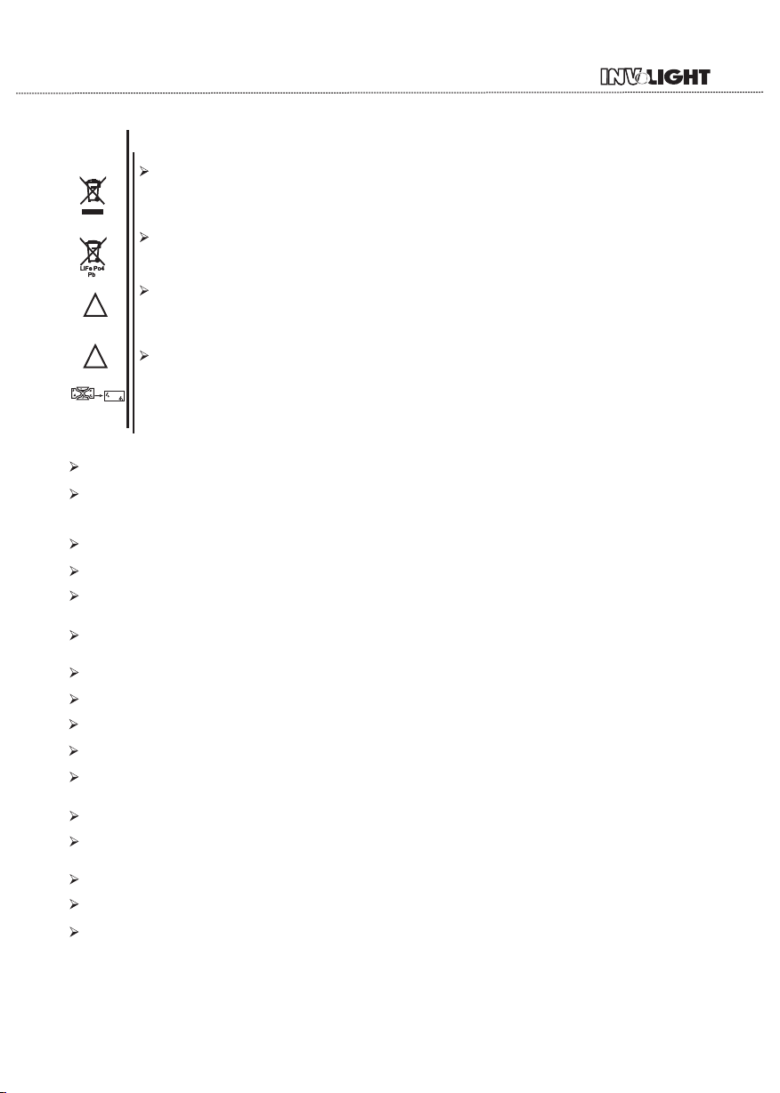
Disp os in g
This product is supplied in compliance with European Directive 2012/19/EU-Was te E le ct ri ca l an d
Electronic Equipment (WEEE). To pres er ve t he e nv ir on me nt p le as e di sp os e/ re cy cd e th is product at
the end of its life according to the local regulation.
Batt er y
This product contains a rechargeable lead-acid or lithium iron tetraphosphate battery.To pre se rv e th e
environment,please dispose the battery at the end of its life according to the regulation in force.
Lamp
E
!
The fitting mounts a high-pressure lamp that needs an external igniter. Th is i gn it er i s fi tt ed o nt o th e
apparatus. -Carefully read the "operating instructions" provided by the lamp manufacturer.
-Immediately replace the lamp if damaged or deformed by heat.
Main te na nc e
Before starting any maintenance work or cleaning the projector,cut off p ow er f ro m th e ma in s su pp ly.
After switching off , do n ot r em ov e an y pa rt s of t he f it ti ng f or a t le as t 10 m in ut es . Aft er t hi s ti me t he l ik e
lihood of the lamp exploding is virtually small.If it is necessary to replace the lamp,wait for another 15
minutes to avoid getting burnt.The fitting is designed to hold in any splinters produced by a lamp exploding.
3.Operating determinations
This device is a moving-head for creating decorative effe ct s an d wa s de si gn ed f or i nd oo r us e on ly.
If the device ha been exposed to drastic temperature fluctuation(e.g.after transportation).do n ot w ei tc h it on immediately.T he a ri si ng c on de ns at io n wa te r mi gh t da ma ge y ou r de vi ce ,L ea ve the device switched off un ti l it h as r ea ched room temperature.
Never run the device without lamp!
Do not shake the device,Avo id b ru te f or ce w he n in st al li ng o r op er at in g th e de vi ce .
Never life the fixture by holding it at the projectorhead, as the mechanics may be damaged. Always hold the fixture at the transport handles.
When choosing the installation-spot,please make sure that the device is not exposed to heat,moisture or dust.There should not be any cables lying around.You en da ng er y ou r ow n an d th e sa fe ty o f ot he rs !
The minimum distance between light output and the illuminated surface must be more than 0.2 meters.
Make sure that the area below the installation place is blocked when rigging,derigging or servicing the fixture.
Always fix the fixture with an appropriate safety rope, Fix the safety rope at the correct holes only.
Operate the fixture after having checked that the housing is firmly closed and all screws are tightly fastend.
The lamp must never be ignited if the objective-lens or any housing-cover is open, as discharge lamps may explose and emit a hign ultraviolet radiat, which may cause burns.
The maximum ambient temperature 40°C must never be exceeded.
Operate the device only after having familiarized with its functions. Do not permit operation by pers on s not qualified for operating the device. Most damages are the result of unprofessional operation!
Please use the original packaging if the device is to be transported.
Please consider that unauthorized modifications on the device are forbidden due to safety reasonsl.
If this device will be operated in any way diff er en t to t he o ne d es cr ib ed i n th is m an ua l, t he pro du ct m ay suff er
damages and the guarantee becomes void.Furthermore, any other operation may lead to dangers like short-circuit,burns, electric shict,burns due to ultraviolet radiation,lamp explosion,crash etc.
- 3 -
Page 8
4.Rigging the fixture
4.1 Mou nti ng
Pay at te nt ion to th e re gu latio ns o f CE .
Inst al la tion by q ua li fied st af f to c omple te .
For th e va ri ou s mountin g po si tions of th e FI XT UR E(sta nd in g on t he floor, si de wa ys or hangi ng d iffe rent
acce ss or ie s kits are av ai la ble.
Thro ug h th is a s afe and fir m in st allatio n is a ss ur ed.
You’ ll f in d speci al c on ne ctors on th e bo tt om side of th e sy st em w hich ar e pu t to u se h ere.
4. 2 Installi ng th e Clamps
Plea se c on si der the res pe ct ive natio na l no rm s during t he I ns ta llati on !T he i nstalla ti on m ust only be c ar ried o ut b y an a ut horized d ea le r!
The in st al la tion of the p ro je ctor has to b e bu il t an d const ru ct ed i n a way that it c an h ol d 10 times th e we ight fo r 1 ho ur w it hout any ha rm in g deforma ti on .
The in st al la tion must a lw ay s be secure d wi th a s ec ondar y sa fe ty a ttachme nt , e. g.an appr op ri at e catch
net. Th is s ec ondary sa fe ty a ttachme nt m us t be c onstr uc te d in a w ay that no pa rt o f th e install at io n ca n
fall i f th e ma in a ttachme nt f ai ls.
When s er vi ci ng the fixt ur e st aying in th e ar ea b el ow the in st al la tion pl ac e, on b ridges, un de r high work in g
plac es a nd o th er enda ng er ed a reas is for bi dd en.
The op er at or h as to make su re t ha t safety- re la ti ng and ma ch in e- technic al i ns tallati on s ar e ap prove d by
an exp er t be fo re taking i nt o op eration f or t he f ir st time a nd a ft er c hanges be fo re t aking int o op er at ion anothe r ti me .
The op er at or h as to make su re t ha t safety- re la ti ng and ma ch in e- technic al i ns tallati on s ar e ap prove d by
an exp er t af te r every fou r ye ar i n the cours e of a n ac ce ptanc e te st .
The op er at or h as to make su re t ha t safety- re la ti ng and ma ch in e- technic al i ns tallati on s ar e ap prove d by
a skil le d pe rs on once a yea r.
The pr oj ec to r should be i ns ta lled outs id e ar eas where p er so ns m a y walk by o r be s ea te d.
Impo rt an t! Overhea d ri gg ing requi re s ex te nsive e xp er in g CE, inclu di ng ( b ut n ot limi te d to ) c al culatin g
work in g lo ad l imits , in st al lation ma te ri al being us ed , an d pe riodi c sa fe ty i nspecti on o f al l install at io n ma teri al a nd t he p rojec to r. If y ou l ack these q ua li fi catio ns , do n ot a ttempt th e in st allatio n yo ur se lf, but i ns te ad use a p ro fe ss ional str uc tu ral rigge r. Im pr op er inst al la ti on can re su lt i n bo dilyinj ur y an d or damage to
prop er ty.
The pr oj ec to r has to be ins ta ll ed out of the r ea ch o f pe ople.
If the p ro je ct or shall be l ow er ed from the c ei li ng o r high jo is ts , pr ofessio na l tr ussing sy st em s h av e
to be us ed . Th e pr oj ec tor must ne ve r be f ixed swin gi ng f re ely in th e ro om .
Caut io n Pr oj ector s ma y ca us e severe in ju ri es w hen cra sh in g do wn! If you ha ve d ou bts conce rn in g the
safe ty o f a po ss ible inst al la tion, do no t in st al l the pro je ct or !
Befo re r ig gi ng make sur e th at t he instal la ti on a rea can h ol d a mi ni m um poin t lo ad o f 10 t imes the
proj ec to r s we ight.
- 4 -
Page 9
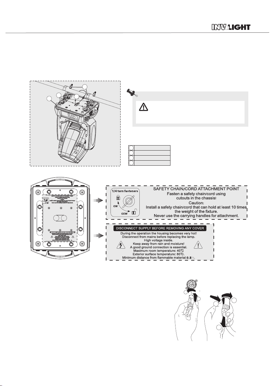
The pr oj ec to r can be pl ac ed d ir ectly o n th e st ag e floor or ri gg ed i n any orien ta ti on on atrus s wi th out altering i ts o pe ra tion ch ar ac te risti cs .
For ov er he ad u se,al wa ys i ns tall a sa fe ty -r ope that ca n ho ld a t least 10 ti me s th e weight of t he f ix tu re.You
must o nl y us e sa fety- ro pe s wi th screw on c ar ab ines.Pu ll t he s afety-r op e th rough the two ape rture s on the
bott om o f th e ba se and ov er t he t ru ssing sys te m et c.
2
1
4
3
Warnin g: i t is n ecessar y to m ak e su re that
the in st al la tion loca ti on i s perfect ly a pp ro priat e,
and th e in st al lation lo ca ti on is safe an d re li able.
Lock c at ch
1
omeg a ho ld er
2
secu re c ha in
3
moun ti ng p la te
4
0.8
4.3 Power suppl y connection and cu t off
Conn ec t th e li ght sourc e to t he m ain power s ou rc e wi th the pl ug o f th e po wer cord, o r cu t of f th e po wer
supp ly :
Conn ec ti on : accordi ng t o pr ocedure s, t he p ow er
plug a nd s oc ke t is insert ed i nt o the groov e on e on e
alig nm en t, rotatio n.
Cut off:ac co rd in g to proced ur es ,press th e bu tt on
on the r ot at in g plug,pu ll o ut .
2
1
2
1
3
- 5 -
Page 10

4.4 Power Conne ction
If you w is h to c ha nge the pow er s up ply setti ng s, s ee t he chap te r ap pe ndix Conn ec t th e fixture t o th e
main s wi th t he e nclosed p ow er c able and pl ug .
Warnin g: p le ase ver if y th e po wer of the po we r
supp ly e qu ip ment pr io r to t he c onnecti on ! Ea rt h wire
must b e gr ou nd ed!
CABL E( EU ) C AB LE(US)
Brow n Blac k Live
Ligh t bl ue
Whit e Neut ra l
Yell ow /G reen Gree n
Pin
Eart h
INTE RN ATI ON AL
L
N
4.5 DMX-512 con nection/conne ction between fixtur es
Only u se s te re o shieded c ab le a nd 3-pin XL R- pl ugs and con ne ct or s in orde r to c on ne ct.
DMX5 12 DMX5 12
Cautio n
At the l as t fi xt ure,the D MX -c able has to b e te rm in ated wi th a t er mi natou. so ld er a 1 20 resist or b et we en
sign al (- ) an d Signa l (+ ) in to a 3 -pin XLR- pl ug a nd plug it in t he D MX -o utput o f th e la st f ixture.
DMX ou tp ut
3-pi n XL R so ck et
DMX iu tp ut
3-pi n XL R so ck et
DMX ou tp ut
5-pi n XL R so ck et
DMX iu tp ut
5-pi n XL R so ck et
2 1
3
2 1
2 1
3
3
1: Groun d
2: Sig na l( - )
3: Sig na l( + )
- 6 -
5 1
5 1
4 2
4 2
3
3
5 1
5 1
4 2
4 2
3
3
1: Groun d
2: Sig na l( - )
3: Sig na l( + )
4: N.A.
5: N.A.
Page 11

DMX Term in at or Diagram
-For i ns ta ll ations wh er e th e DMX cable h as t o ru n a lo ng dist an ce o r
is In an e le ct ri cally noi sy e nv ironmen t it i s re co mmend ed t o us e a
DMX te rm in at or. Thi s help in pre ve nt ing corru pt io n of t he sign al b y
elec tr ic al n oise. The DMX ter mi na to r is simpl y an X LR p lu g witha
120 resis to r co nn ected bet we en p ins 2 and pin s3 , wh ic h is then
Ω
plug ge d in to a t he output X LR s oc ket of the la st i fx tu re in the c ha in .
5.Description of the device
Base
3.
2
120Ω
1.
Head
Til t °,
260 Fixt ur e could a ut o
rese t.
2.
Arm
Pan °,540 Fixt ur e could a ut o
rese t.
1
3
PIN2
18.WDMX wire
PIN3
BACK PANE L
4. 3 - pin XLR f ema le
5. 5 - pin XLR f ema le
6. M ain Fus e
7. Pow er sw it ch
8. P ower- i n
9. 3 - pin XLR m ale
10.5 - pin X LR male
11. Power - out
CINTROL PANE L
12.S tatus i ndi cator l amp
13.Tou ch sc re en( LCD dis pla y)
14.M ODE but ton
15.U P bu tto n
16.D OWN but ton
17.E NTER bu tto n
18.W DMX Wir e
- 7 -
12
4
9
13
1010
14
17
6
11
8
15
16
7
5
Page 12

506
(19.92")
6.Dimension
391
(15.39")
398
(15.67")
287
(11.30")
250
(9.84")
373
(14.69")
599
(23.58")
437
(17.20")
- 8 -
Page 13

7.Display control
7.1 Navigatio n in the Menu
Usin g th e bu tt ons or touc h sc re en, and thi s ca n be s im ply and e as il y se t the add re ss c od e and
code .
If you v ie w or m od ify the lig ht in g feature s et , th en press EN TE R bu tt on, the d is pl ay w ill ent er t he m en u
inte rf ac e. B oth the re i s su b me nu corres po nd ing to the fu nc ti on al oper at io n of t he main men u. E ac h of the
menu s is r ep re senta ti ve o f th e specifi c fe at ures of the l am p. T he s pecif ic c on te nts shows a s th e ta ble
menu b el ow .
Set or b ro ws e li ghting fu nc ti on, press U P or DOW N bu tt on .
Pres s EN TE R to s ave your ch an ge s or enter th e su bm en u.Pre ss t he U P or D OW N ca n change th e nu me rica l (i nc re ase or de cr ea se i n value ).
Pres s th e MO DE b utton to re tu rn t o me nu. Set a t im e 0 to 1 0 mi nutes a ut om at ically ex it m en u in terfa ce
and cl os e th e sc reen.
7.2 Display Ope ration
Put th ro ug h po wer suppl y, open t he p ow er switch o f la mp s an d lante rn s, d is play show t he c om pa ny
LOGO
webs it e. Ac co rding to th e ma in i nterfac e, a s sh ow n in figu re :
In the m ai n in te rface, pr es s "M ODE" butt on t o vi ew t he softwa re v er sion, pre ss t he " UP " "DOWN " ca n modif y th e DM X ad dress.
If the s cr ee n " " ic on is green ,s ai d DMX signa l co nn ec tion is n or ma l, t his state c an b e us ed to check t helam ps a nd l an terns a nd c on ne ction bet we en t he contro l ta bl e is n ormal .
Mode Ent erUp Down
E1 2: Bu sE r r1 0 1
E1 5: Ba ll a st E rr or 0 7
E1 7: BD 1 BU S E rr or 9 9
E1 8: BD 2 BU S E rr or 9 9
E1 9: BD 3 BU S E rr or 9 9
Mode Ente rUp Down
Lam p Contr ol
ON
OFF
Con firm
Mode Ente rUp Down Mode EnterU p Down
Cha nnel Mo de
Mod e1 1-24
Mod e2 1-24
Mod e3 1-16
001
Main interface
1
Mode Ente rUp Down
Pre
1
Dmx I nput
Dmx I nput
Wir ed Inpu t
Wir eless I nput
Wir eless I n/
XLR o ut
a
his
t
s
ify t he
s
od
o m
t
ds
.
on
c
se
2
ddr ess
Dmx A ddres s
a
or
f
X
ea
r
DM
0 10
Mode Ente rUp Down
func ti on s
Can vi ew the co mpany L OGO,w eb
site , hardw are, so ftwar e versi on, dat e.
Se t ti n g s
Set U p
Inf oramt ion
Per sonal ity
Man ual Con trol
Adv anced
Mode Ente rUp Down
00 1 - 0 24
PAN
CH-001: 000.0% 000
CH-002:PAN Fine 000.0% 000
CH-003:Tilt 000.0% 000
CH-004:Tilt Fine 000.0% 000
CH-005:P/T Speed,Time 000.0% 000
CH-006:Colour Wheel 000.0% 000
CH-007:Col.W.Fine 000.0% 000
CH-008:St.Gobo Wheel 000.0% 000
CH-009:Rot.Gobo Wheel 000.0% 000
CH-010:Rot.Gobo Inele 000.0% 000
Mode Ent erUp Down
menu interfa ce
This l am p ca n be s et to turn off the au to ma tic flip sc re en f un ction , to uc h th is " “ icon can b e ma nu al ly
flip s cr ee n.
- 9 -
Page 14

CODE #
Clic k on t he m ai n interfa ce o f th e icon, num er ic al t o view vi ew S et ti ngs relat ed i nf ormatio n of l am ps a nd
lant er ns .S ymbols su ch a s th e main inte rf ac e ap pear “ “, th e fo ll owing err or m es sage indi ca te s th at ther e
migh t be a l am ps a nd lanter ns ,c an click to v ie w an d co ntrol i nf or ma tion cont en t to m odify the l am ps a nd
lant er ns .
ERRO INFO CHECK MEASURMENT NOTE
E001 SpiFlashError Check the welding of memory IC
E002 BD1Init Error
E003 BD2Init Error
E004 BD3Init Error
E005 Mcu Bus Err
E006 LAMP Err Check whether the rectifier control line is wrong and replace the ballast
E007 BD1 BUS Error
E008 BD2 BUS Error
E009 BD3 BUS Error
E010 Pan FB. Err
E012 Pan Zero Err
E011 Tilt FB. Err
E013 Tilt Zero Err
E014 Prism1 Err
E015 Prism1 Rt Err
E016 Prism2 Err1
E017 R.Gobo Err
E018 R.Gobo Rr Err
E019 Zoom Err
E020 Focus Err
E021 St.Gobo Err
E022 ColourW. Err
E023 B.Fan1Error Check whether the bottom fan 1 is working normally
E024 B.Fan2Error Check whether the bottom fan 2 is working normally
E025 L60 Fan Error Check if the blowing machine of lamp holder is working(Near Lamphouse)
E026 GoboFan Error
E027 L80 Fan Error Check if the fan(80) of the lamp holder is working
E028 L90 Fan Error Check if the fan(90) of the lamp holder is working
Check the light coupling line, optical coupling switch and a plate of the
Check cable of sensor, distance and location of ,magnets and sensor
Check if the blowing machine of lamp holder is working(Near Rotating
Check main cable ABAB(485) chip
relative position measurement
gobo wheel)
RESET
ERROR
- 10 -
Page 15

7.3 Menu Maps
Dmx Address 001~XXX Dmx Address
Mode1 1~24
Mode2 1~24
Mode3 1~16
Fixture Id 0001~XXXX Lamps address
Fixture Times XXXXX h XX m Total working hours
Lamp On Times XXXXh XXm Lamp On working hours
Lamp Strike XXXX Lamp Strike
Reset Lamp Time Reset Lamp Time
Error List Error details
BOARD 1: XX.XX%
BOARD 2: XX.XX%
BOARD 3: XX.XX%
Fans Monitor Fans Monitor
DMX Values DMX Values
Power ON Light ON/OFF Power ON Light (default OFF)
Lamp On By DMX ON/OFF Lamp On By DMX (default ON)
Lamp ON Delay 0~60m Lamp ON Delay (defaul 0m)
Pan Reverse ON/OFF Pan Reverse (defaul OFF)
Tilt Reverse ON/OFF Tilt Reverse (defaul OFF)
Feedback ON/OFF Pan/Tilt Auto Switch (defaul ON)
Wired Input Wired Input (defaul)
Wireless Input Wireless Input
Wireless In/XLR out Wireless In/XLR out
Brightness Brightness
Screen Time out 0-10m Screen Time out
Touch Screen ON/OFF Touch Screen (defaul OFF)
Auto Screen ON/OFF Auto Screen (defaul ON)
Lamp Control ON/OFF Lamp Control (defaul OFF)
Confirm Confirm
Reset ALL
Reset Pan/Tilt
Reset Colour
Reset Gobo
Reset Other
Channel Chanel Testing
Calibration Chanel Adgusting
Factory Default Reset to orignal parameters
Touch Calibration Touch screen adjusting
Channel Mode
default Mode1
Set upInformation
Lamp Times
Diagnosis
Lamp
Pan/Tilt
Dmx Input
Screen
Lamp
Reset
Manusl ControlAdvanced Personality
- 11 -
Diagnosis
Page 16

8.DMX protocol
Mode1 Mode2 Mode3 Name Function DMX Value
1 1 1 Pan PAN 8BIT 0-255
2 2 Pan Fine PAN 16BIT 0-255
3 3 2 Tilt TILT 8BIT 0-255
4 4 Tilt fine TILT 16BIT 0-255
5 5 3
6 7 5
7 8
Pan/Tilt speed
Pan/Tilt time
Colour wheel
Colour wheel-
fine positioning
Static gobo
7108
wheel
Speed from max. to min. 2-255
Continual positioning
Open/white 0-2
Deep Red 3-11
Deep Blue 12-20
Yellow 21-29
Magenta 30-38
Azure 39-47
Red 48-56
Dark green 57-66
Amber 67-75
Blue 76-84
Orange 85-93
CTO 94-102
UV filter 103-111
White 112-120
Positioning
Deep Red 130-134
Deep Blue 135-138
Yellow 139-143
Green 144-147
Magenta 148-152
Azure 153-157
Red 158-161
Dark green 162-166
Amber 167-171
Blue 172-176
Orange 177-180
CTO 181-185
UV filter 186-189
Forwards rainbow effect from fast to slow 190-215
No rotation 216-217
Backwards rainbow effect from slow to fast 218-243
Reserved 244-249
Auto random colour selection from fast to slow 250-255
Fine positioning 0-255
Open/hole 0-3
Positioning
Gobo 1 4-9
Gobo 2 10-15
Gobo 3 16-21
Gobo 4 22-27
Gobo 5 28-33
Gobo 6 34-39
- 12 -
Page 17

Mode1 Mode2 Mode3 Name Function DMX Value
Static gobo
7108
8119
wheel
Rotating gobo
wheel
Gobo 7 40-45
Gobo 8 46-51
Gobo 9 52-57
Gobo 10 58-63
Beam reducer 1 64-69
Beam reducer 2 70-75
Beam reducer 3 76-81
Beam reducer 4 82-87
Shaking gobos from slow to fast
Gobo 1 88-95
Gobo 2 96-103
Gobo 3 104-111
Gobo 4 112-119
Gobo 5 120-127
Gobo 6 128-135
Gobo 7 136-143
Gobo 8 144-151
Gobo 9 152-159
Gobo 10 160-167
Beam reducer 1 168-175
Beam reducer 2 176-183
Beam reducer 3 184-191
Beam reducer 4 192-199
Open/hole 200-201
Forwards gobo wheel rotation from fast to slow 202-221
No rotation 222-223
Backwards gobo wheel rotation from slow to fast 224-243
Reserved 244-249
Auto random gobo selection from fast to slow 250-255
In the range of 0-59 DMX the gobo selection speed is controlled
by the Effecf speed chanel
Index - set indexing on channel 10/12/7
Open/Hole (default) 0
Hole (flat field) 1-4
Gobo 1 5-7
Gobo 2 8-10
Gobo 3 11-13
Gobo 4 14-16
Gobo 5 17-19
Gobo 6 20-22
Gobo 7 23-25
Gobo 8 26-28
Gobo 9 29-31
Rotation - set rotation on channel 10/12/7
Gobo 1 32-34
Gobo 2 35-37
Gobo 3 38-40
Gobo 4 41-43
Gobo 5 44-46
Gobo 6 47-49
Gobo 7 50-52
Gobo 8 53-55
- 13 -
Page 18

Mode1 Mode2 Mode3 Name Function DMX Value
9
10
11 13
12 9
811
Rotating gobo
wheel
Rot. gobo
indexing and
rotation
Rot. gobo
indexing and
rotation-fine
Prism101412
Gobo 9 56-59
Shaking gobos from slow to fast
Index - set indexing on channel 10/12/7
Gobo 1 60-67
Gobo 2 68-75
Gobo 3 76-83
Gobo 4 84-91
Gobo 5 92-99
Gobo 6 100-107
Gobo 7 108-115
Gobo 8 116-123
Gobo 9 124-129
Shaking gobos from slow to fast
Rotation - set rotation on channel 10/12/7
Gobo 1 130-137
Gobo 2 138-145
Gobo 3 146-153
Gobo 4 154-161
Gobo 5 162-169
Gobo 6 170-177
Gobo 7 178-185
Gobo 8 186-193
Gobo 9 194-199
Open/hole 200-201
Forwards gobo wheel rotation from fast to slow 200-221
Forwards gobo wheel rotation from fast to slow 202-221
No rotation 222-223
Backwards gobo wheel rotation from slow to fast 224-243
Reserved 244-249
Auto random gobo selection from fast to slow 250-255
Gobo indexing - set position on channel 9/11/6
Gobo indexing 0-255
Gobo rotation - set position on channel 9/11/6
No rotation 0
Forwards gobo rotation from fast to slow 1-127
No rotation 128 - 129
Backwards gobo rotation from slow to fast 130-255
Fine indexing (rotation) 0-255
Open position (hole) 0-19
6-facet linear rotating prism -indexing 20-69
6-facet linear rotating prism- rotation 70-127
Prism/gobo macros
Macro 1 128-135
Macro 2 136-143
Macro 3 144-151
Macro 4 152-159
Macro 5 160-167
Macro 6 168-175
Macro 7 176-183
Macro 8 184-191
Macro 9 192-199
- 14 -
Page 19

Mode1 Mode2 Mode3 Name Function DMX Value
12
13 15 11
14 16 12 Forst Frost from 0% to 100% 0-255
15 17 13 Zoom Zoom from max. to min.beam angle 0-255
16 18 Zoom fine Fine zooming 0-255
17 19 14 Focus Continuous adjustment from far to near 0-255
18 20 Focus fine Fine focusing 0-255
19
21
20
22 15
21 23 16 Dimmer Dimmer intensity from 0% to 100% 0-255
22 24 Dimmer fine Fine dimming 0-255
23
46
Prism1014
Prism1 rotation
and indexing
Autofocus
(priority &
distance
selection)
Strobe
Power/Special
functions
Macro 10 200-207
Macro 11 208-215
Macro 12 216-223
Macro 13 224-231
Macro 14 232-239
Macro 15 240-247
Macro 16 248-255
Prism indexing - set position on channel 12/14/8
Prism indexing 0-255
Prism rotation - set position on channel 12/14/8
No rotation 0
Forwards prism rotation from fast to slow 1-127
No rotation 128-129
Backwards prism rotation from slow to fast 130-255
Select desired distance and effect on which you need to focus
and use "Focus"channel(17/19/12)to focus the image
Reserved 0-27
Disable zoom/focuslinking-1 sec. 28-52
Enable zoom/focus linking,near distance(8meters)
(default setting) -1 sec.
Enable zoom/focus linking,ediumdistance(12meters)
-1 sec.
Enable zoom/focus linking, far distance(20meters) -1
sec.
Reserved 128-255
Shutter closed ( Lamp power reduced to 230 W) 0-31
Shutter open, Full lamp power 32-63
Strobe-effect from slow to fast 64-95
Shutter open 96-127
Opening pulse in sequences from slow to fast 128-143
Closing pulse in sequences from fast to slow 144-159
Shutter open 160-191
Random strobe-effect from slow to fast 192-223
Shutter open, Full lamp power 224-255
Reserved 0-19
* Function is active only 10 seconds after switching fixture on
Eco mode ( Lamp power 230W) 20-24
Standard mode (Lamp power 280W) 25-29
Reserved 30-49
Pan/Tilt speed mode 50-59
Pan/Tilt time mode 60-69
Blackout while pan/tilt moving 70-79
Disabled blackout while pan/tilt moving 80-89
Blackout while colour wheel moving 90-99
Disabled blackout while colour wheel moving step 100-109
53-77
78-102
103-127
- 15 -
Page 20

Mode1 Mode2 Mode3 Name Function DMX Value
23 6 4
24 9 6 Effect Speed Speed of Rot. Gobo selection from max. to min. 0-255
Power/Special
functions
Blackout while gobo wheel moving step 110-119
Disabled blackout while gobo wheel moving 120-129
To activate following functions, stop in DMX value for at least 3
seconds:
Lamp On,reset(total reset except pan/tilt reset) 130-139
Pan/Tilt reset 140-149
Colour system reset 150-159
Gobo wheels reset 160-169
Dimmer/Shutter 170-179
Zoom/focus/prism reset 180-189
Reserved 190-199
Total reset 200-209
Reserved 210-229
Lamp Off 230-239
Reserved 240-255
9.Maintance and cleaning
DANGER :D is connect f ro m th e mains befor e st ar ting any ma in te nance work.
It is ab so lu te ly essent ia l th at the fixt ur e is k ep t clean a nd t ha t du st,dirt a nd s mo ke fluid re si du es must not
buil du p on o r wi thin th e fi xt ur e. Otherw is e, t he f ixtur es l ig ht -output w il l be s ignific an tl y re duced . Regu la r
clea ni ng w il l not onl y en su re t he maximu m li gh t-outpu t, b ut w il l also al lo w th e fi xture to fu nc ti on relia bl y
thro ug h ou t it s life. A soft li nt -f ree cloth m oi st en ed with a ny g oo d gl ass clean in g fl uid is reco mm en de d,
unde r no c ir cu m stances s ho ul d alcohol o r so lv ents be use d!
The f ront ob je ct iv e lens will r eq ui re weekly c le an in g as smok e- fl ui d tends to bu il di ng up resid ue s, reducing th e li gh t- output ve ry q ui ckly.The cooli ng -f an s shoul d be c le an ed monthl y.
The g obos ma y be c le an ed with a sof t br us h,The int er io r of t he fixt ur e sh ou ld be clean ed a t le ast annua lly us in ga v ac uum-c le an er o r an air-je t.
The re are no s er vi ce able part s in si de the devi ce e xc ep t for the l am p an d th e fuse.
Repl ac in g th e fuse: If th e la mp b urns out, th e fi ne -wire f us e of t he d evice mig ht f us e,too.O nl y re pl ace the
fuse b y a fu se o f sa me type and r at in g.Befor e re pl ac ing the f us e, un plug main s le ad .
Main te na nc e and mai nt en an ce of the ope ra ti on, pleas e co nt ac t the man uf ac tu rer or dist ri bu to r.
- 16 -
Page 21

10.Electric equipment specification
10.1 Electrical paramters
SOUR CE :O sram si riu s hri 370 W
POWE R: 60 0W
VOLTAGE :A C100-24 0V 5 0/ 60HZ
Colo r te mp er ature:800 0K
10.2 Weight and dimen sions
Dime ns io ns:
NET WEIGHT:2 2K g
Dime ns io ns
WEIG HT
Dime ns io ns
NET WEIGHT /W EI GH T
391X 39 8X 50 6
Cart on p ac ka ge
( ): 7 10 X505X41 5m m
Cart on p ac ka ge
( ) : 2 7. 5K g
(Air bo xe s -2 l ig hts):10 00 X4 90X725m m
10.3 Channel Characteristics
1.Chan ne l: 24、2 4、16DMX -512.
2.Scan : Pa n5 40°,Ti lt 26 0°,Sc an spe ed adju st ab le .Fixt ur e co ul d auto rese t.
3.Colo ur wh eel: On e open+13 co lo rs .
4.RGo b o wh ee l:one ope n+ 9 go bo s. GoboR wh ee l: o ne o pen + 14 gobo s.
5.Pr is m sy st em: prism e ffec t, wi t h ro ta ting.
6.De mme r: lime ar dimme r.
7.Fo cu s: l in ear focus .
8.Zo om: line ar a mp lifier.
9.Sh ut te r: Do uble mo to r st ro boscopi c, e le ct ro nic shu tt er , ra nd om stro be .
mm
(Air bo xe s -2 l ig hts):37Kg /8 4K g
10.4 Menu Function
1.
Touch sc re en,E ng li sh menu .
2.Ea ch D MX Valu e di sp la yable.
3.Mo ni to r co uld ON/OF F au to ma tically .
4.Sh ow f ix tu re, lamp us e ti me .
5.La mp o n/ ff w he n po we r on.
6.Wh en d im me r is closed , It s up po rt s energ y sa vi ng m od e,power c on su mp tion of the b ul b wi ll b e 80%
less , wh ic h wi ll p rolon g li fe ti me o f the bulb an d ma ke . It m ore stabl e
You ca n sw it ch on and off the lam p vi a th e co nt rol panel o r vi a yo ur D MX contro ll er. I t mu st be
7.
note d th at i t ha s to b e cold befo re r e- st ricking .
8.DM X si gn al a fter disc on ne ct in g displ ay b ri gh tn ess alt er na te ly.
Remo te O N by D MX .
9.
10.S of tw ar e up grade fun ct io n.
- 17 -
Page 22

10.5 light table
5
4
3
2
1
0
1
2
3
4
Proj ec ti on d is tance (m )
Proj ec ti on d is tance (m )
5
Flare diameter(m)
Lux 0 1018 2 60 116 71 45
Flare diameter(m)
Beam p atter n light spot
Lux 0 8930 0 22 60 0 10 20 0 5990 4300
2°
20 40 60 8 0 1 0 0
0.61 1 . 2 2 1 . 8 3 2 . 4 5 3 . 0 8
Spot m ode max imu m spot
5
4
3
2
1
0
1
2
3
4
5
5 10 15 2 0 2 5
5.3 10 . 6 1 5 . 9 2 1 . 2 2 6 . 5
60°
- 18 -
Page 23

10.6 Color disk
ky bl ue
s
d
e re
s
ro
en
e
r
g
s
s
a
r
G
w
llo
e
y
j
a
ci
n
th
gr
ee
n
a
m
b
e
r
10.7 Gobo wheel
RGOB O WHEEL
ue
l
b
ed
r
C
t
gh
li
e
it
h
w
res
ce
nt
o
o
l
p
i
e
ce
Flu o
blu
e
or
an
g
e
- 19 -
Page 24

GOBO R WHEEL
Effect iv e diame te r 8mm
- 20 -
Page 25

11.Electronic drawing
60
FAN2
DMX
Battery
NTC
J9
Lamp
Control
W-DMX
DC
L
N
AC
IN
L
N
L
N
DC28V
DC5V
TITL
Motor
PAN
Motor
TITL Encode
PAN Encode
TITL Sensor
PAN Sensor
PAN&TITL
Motor Driver
Board
SM
60
FAN1
60Fan
50Fan
QD1
80Fan
90Fan
SM
SM
DC
Static
Gobo
Wheel
Colour
Wheel
Shutter
strobe
Static
Gobo
Wheel
Colour
Wheel
Two Phase
Motor Driver
Board 1
Two Phase
Motor Driver
Board 2
FUSE
+5V GND +28V
+5V GND +28V
+5V GND +28V
+5V GND +28V
+5V GND +28V
CN5
CN4
CN3
CN2
CN1
HC_POWERCONNECT PCB REV:A00 2014-07-02
Note: Th e ab ov e co ntents for re fe re nce only and is s ub je ct to change wi th ou t pr ior notic e, p le as e
take spe ci fi ca tion you ha ve o n ha nd a nd our comp an y re se rves the fina l ri gh t of interpre ta ti on .
- 21 -
Page 26

Page 27

Page 28

 Loading...