

Involar MAC250, MAC250-230-EUR Installation And Operation Manual
Version 4 Rev 1 Apr 2011 INVOLAR Corporation Ltd. (EUR)
1
Installation and Operations Manual
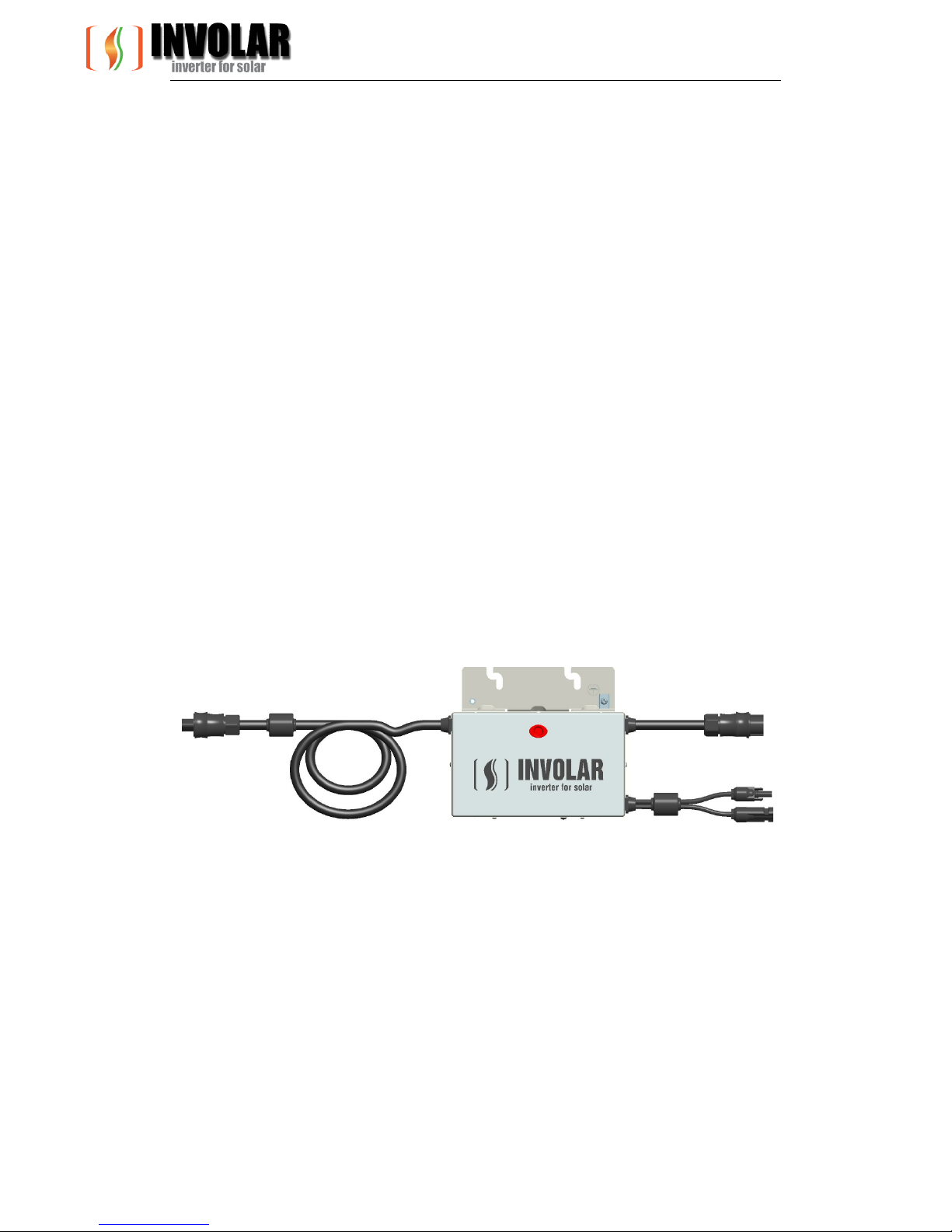
INVOLAR MAC250 Photovoltaic Micro-Inverter
Model number MAC250-230-EUR.
This manual is an integral part of the unit. Please read the instruction manual carefully
before installation, operation or maintenance. Keep this instruction manual for future
reference.
This document is not to be reproduced in any manner, nor are the contents to be disclosed
to anyone, without the express authorization of INVOLAR.

Version 4 Rev 1 Apr 2011 INVOLAR Corporation Ltd. (EUR)
2
Contact Information
INVOLAR Corporation Ltd.
Room 501, Building 84, No. 887, Zuchongzhi Road, Pudong
District,
201203 Shanghai, PEOPLE’S REPUBLIC OF CHINA
Tel: 86-21-50272208
Fax: 86-21-50277705
www.INVOLAR.com
info@INVOLAR.com

Version 4 Rev 1 Apr 2011 INVOLAR Corporation Ltd. (EUR)
3
Table of Contents
1 READ THIS FIRST ........................................................................................................................ 4
2 SAFETY SYMBOLS....................................................................................................................... 5
3 SAFETY INSTRUCTIONSAND EC DIRECTIVES ............................................................................... 9
3.1 EC DIRECTIVES ..................................................................................................................... 15
4 THE INVOLAR MICRO-INVERTER SYSTEM INSTRUCTION .......................................................... 24
4.1 THE INVOLAR MICRO-INVERTER SYSTEM .................................................................................. 24
4.2 THE INVOLAR MAC250 MICRO-INVERTER ............................................................................... 25
4.3 FEATURES ........................................................................................................................... 25
5 INVOLAR MICRO-INVERTER INSTALLATION ............................................................................. 26
5.1 INVOLAR MAC250MICRO-INVERTER OPERATIONAL ENVIRONMENT ............................................... 28
5.2 INVOLAR MAC250 MICRO-INVERTER OPERATIONAL CONDITION IN PV SYSTEM ................................ 28
5.3 INSTALLATION STEPS ............................................................................................................. 28
6. FUNCTION INSTRUCTIONS ....................................................................................................... 35
6.1 WORKING MODE ................................................................................................................. 35
6.2 GRID-CONNECTION ............................................................................................................... 36
6.3 GRID DISCONNECT ................................................................................................................ 36
START-UP– CHECKS .......................................................................................................................... 37
7 DISCONNECTING A MICROINVERTER FROM THE PV MODULE ................................................. 38
8 MONITORING AND TROUBLESHOOTING AND MAINTENANCE ................................................. 39
SAFETY CHECKS ................................................................................................................................. 39
MAINTAIN PERIODICALLY .................................................................................................................... 39
8.1 OVERVIEW .......................................................................................................................... 40
8.2 MAC250 MICRO-INVERTER STATUS LED INDICATIONS AND ERROR REPORTING ............................. 41
9 INTERNET WEB ................................................................................................................... 43
9.1 USER REGISTRATION.............................................................................................................. 43
9.2 USER LOGIN ........................................................................................................................ 43
10 INVOLAR MAC250 MICRO-INVERTER TECHNICAL DATA ........................................................... 44
10.1 TECHNICAL SPECIFICATIONS ..................................................................................................... 44
11 APPENDIX ................................................................................................................................ 46
11.1 LIMITED WARRANTY.............................................................................................................. 46
11.2 INVOLAR MAC250 MICRO-INVERTER SYSTEM SAMPLE WIRING DIAGRAM ...................................... 47
11.3 EC DECLARATION OF CONFORMITY ........................................................................................... 48

Version 4 Rev 1 Apr 2011 INVOLAR Corporation Ltd. (EUR)
4
IMPORTANT SAFETY
INSTRUCTIONS
SAVE THESE INSTRUCTIONS
1 Read This First
Thank you for using INVOLAR MAC250-230-EUR Micro-Inverter. This Micro-Inverter with a
revolutionary technology maximizes the energy conversion from photovoltaic solar modules,
enhanced system reliability, and greatly simplifies the installation and reduces the maintenance
time and cost.
To reduce the risk of electrical shock, and to ensure the safe installation and operation of the
INVOLAR MAC250 Micro-Inverter, please read this manual carefully and pay attention to the
safety symbols appear throughout this document.
This manual is for end users.
Version 4 Rev 1 Apr 2011 INVOLAR Corporation Ltd. (EUR)
5
2 Safety Symbols
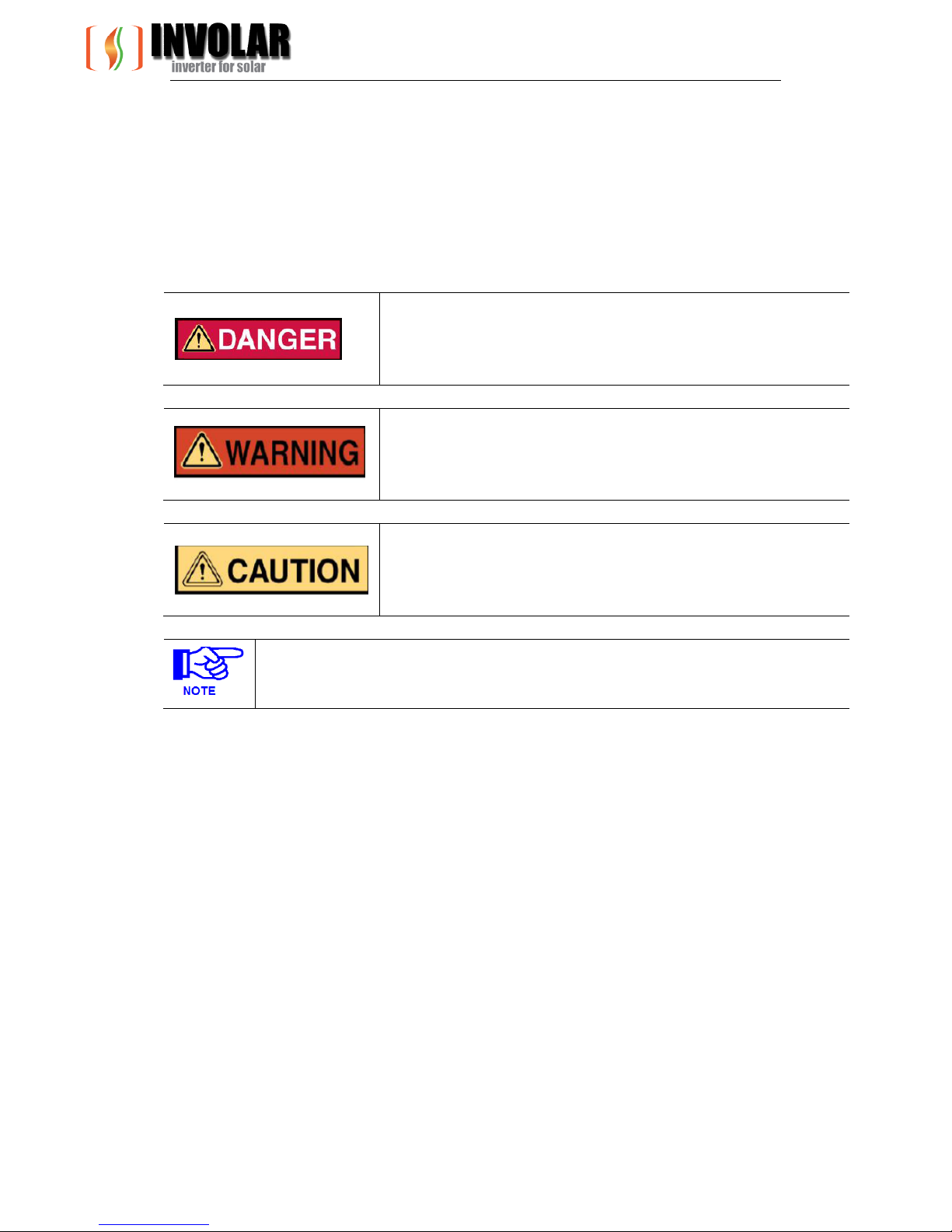
Warnings and cautions tell you about the dangerous conditions that can occur if
you do not follow all instructions in this manual.
Please read following safety symbols to indicate dangerous conditions and
important safety instruction.
DANGER
The DANGER symbols in this manual and on MAC250 Micro-inverter
indicate a hazard with a high level of risk which, if not avoided,
will result in death or serious injury.
WARNING
The WARNING symbols in this manual and on MAC250
Micro-inverter indicates a hazard with a medium level of risk
which, if not avoided, could result in death or serious injury.
CAUTION
The CAUTION symbols in this manual and on MAC250 Micro-inverter
indicate a hazard with a low level of risk which, if not avoided, could
result in minor or moderate injury.
NOTE
The NOTE symbols in this manual indicate the important product information.
Version 4 Rev 1 Apr 2011 INVOLAR Corporation Ltd. (EUR)
6
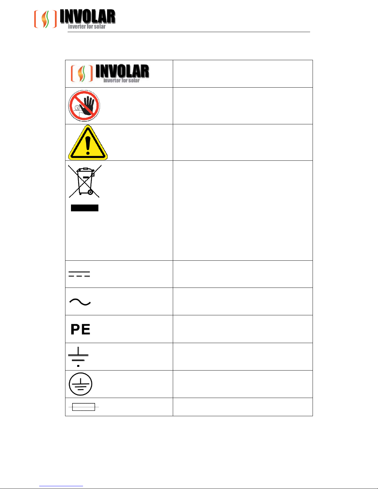
Symbols replace words on the equipment, on a display, or in manuals.
Trademark
No access for unauthorized personal
Caution, risk of danger
Symbol for the marking of electrical and
electronics devices according to Directive
2002/96/EC. Indicates that the device,
accessories and the packaging must not be
disposed as unsorted municipal waste and
must be collected separately at the end of the
usage Please follow Local Ordinances or
Regulations for disposal or contact an
authorized representative of the manufacturer
for information concerning the
decommissioning of equipment.
Direct current
Alternating current
Protective conductor
Earth (ground) TERMINAL
Protective Conductor Terminal
Fuse
Version 4 Rev 1 Apr 2011 INVOLAR Corporation Ltd. (EUR)
7
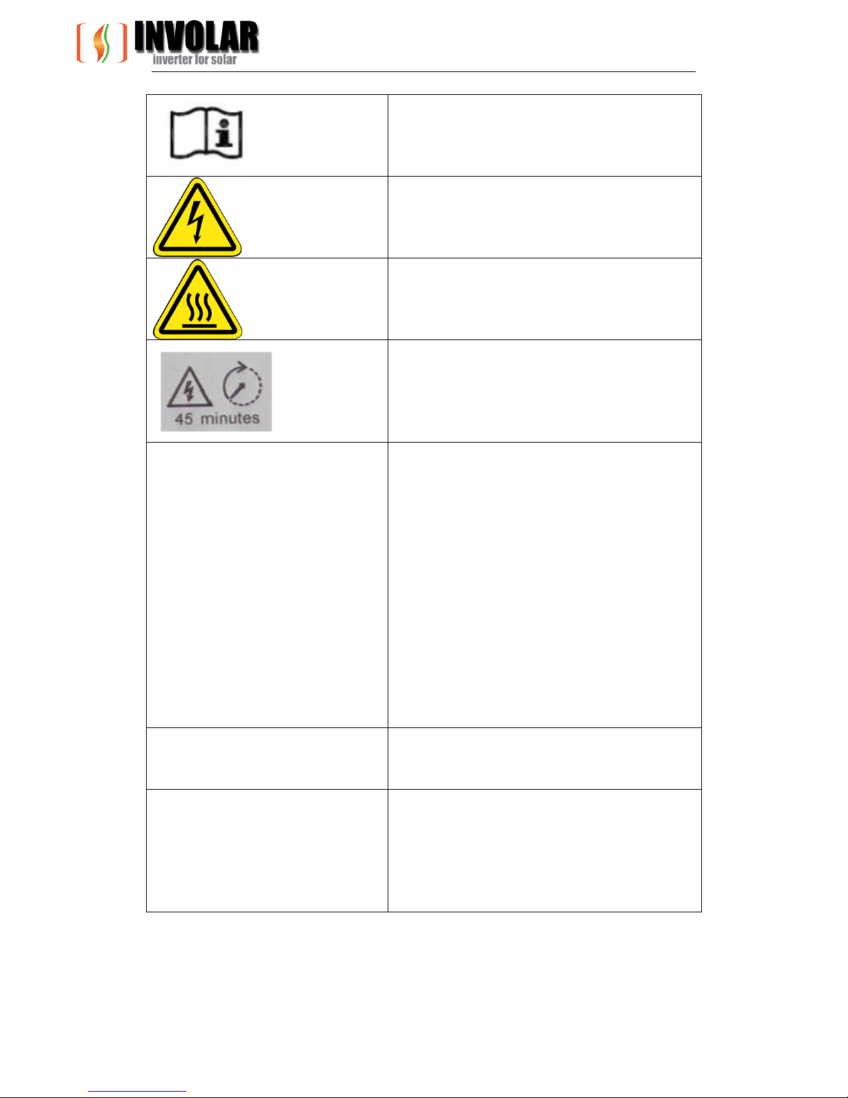
Refer to the operating instructions
Caution, risk of electric shock
Caution, hot surface
RISK OF ELECTRIC SHOCK! Energy storage
timed
Discharge: 45 minutes! Hazardous voltage
present for up to 45 minutes faster
disconnection from power supply.
Isc PV Absolute maximum total PV array short circuit
current (D.C.) that the inverter is rated to have
connected to its PV input, under worst-case
conditions of ambient temperature, irradiance,
etc. This rating of the PCE refers to the
absolute maximum current the PV input to the
solar inverter is designed for under conditions
of expected use. This differs from the simple
sum of the marked Isc ratings of the connected
PV modules, since those markings are based
on short circuit conditions under standard test
conditions, and may be exceeded in cold
temperatures or with irradiance above the
standard level.
OVC Overvoltage category (OVC), numeral
designation defining a classification of
transient overvoltage conditions
Vmax PV Maximum rated D.C. input voltage the PCE is
designed to withstand from the PV array (i.e.
maximum open circuit voltage) under worst
case
conditions of ambient temperature,
irradiance, etc.
Version 4 Rev 1 Apr 2011 INVOLAR Corporation Ltd. (EUR)
8
CE mark is attached to the solar inverter to
verify that the unit follows the provisions of
the European Low Voltage and EMC Directives
PV Photovoltaic
DC terminal, indicating the polarity of the
connections, positive,all positive connections
shall be made with Red
insulated wire
DC terminal, indicating the polarity of the
connections, negative, all negative
connections with black insulated wires
PCS Power conversion equipment, hereby is our
DC/AC inverter
Service Personnel A person having appropriate technical training
and experience necessary to be aware of
hazards to which that person may be exposed
in performing a task and of measures to
minimize the
risks to that person or other persons
Qualified personnel Person adequately advised or supervised by an
electrically skilled person to enable him or her
to perceive risks and to avoid hazards which
electricity can create. For the purpose of the
safety information of this manual, a "qualified
person" is someone who is familiar with
requirements for safety, refrigeration system
and EMC and is authorized to energize,
ground, and tag equipment, systems, and
circuits in accordance with established safety
procedures.
The inverter and endues system may only be
commissioned and operated by qualified
personnel.
DVC
Decisive voltage class
Closed Electrical Operating Area
Room or location for electrical equipment to which
access is restricted to skilled or instructed
persons by the opening of a door or the removal of a
barrier by the use of a key or tool and
which is clearly marked by appropriate warning
signs

Version 4 Rev 1 Apr 2011 INVOLAR Corporation Ltd. (EUR)
9
Technical Competence
The procedures described in this manual should be
performed by a trained and authorized personnel only.
Maintenance should only be undertaken by competent
individuals who have a general knowledge of and
experience with devices of this nature. No repairs
should ever be undertaken or attempted by anyone
not having such qualifications.
Compliance with safety regulations depends upon installing and configuring system correctly,
including using the specified wirings. The system must be installed only by professional
assemblers who are familiar with requirements for safety, Photovoltaic system and EMC. The
assembler is responsible for ensuring that the end system complies with all the relevant laws
in the country where it is to be used.
Involar require using only genuine replacement parts, manufactured or sold by Involar for all
repair parts replacements.
Read completely through each step in every procedure before starting the procedure; any
exceptions may result in a failure to properly and safely complete the attempted procedure.
The individual sub-assembly of the system shall be interconnected by means of the wiring
methods outlined in national/international regulations but not limited to the BS7671
Requirements/ VDE regulation 0107.
All electrical installations must be made in accordance with the National Electrical
regulations, and any other codes and regulations applicable to the installation site.
Servicing of this product in accordance with this manual should never be undertaken in the
absence of proper tools, test equipment and the most recent revision to this manual which
is clearly and thoroughly understood.
3 Safety Instructions and EC Directives
This chapter contains the safety instructions which you must follow when installing,
operating and servicing the unit. If ignored, physical injury or death may follow, or damage
may occur to the unit. Read the safety instructions before you commence work on the unit.
If you are unable to understand the Dangers, Warnings, Cautions or Instructions, contact
the manufacturer or an authorized service dealer before installing, operating and servicing
the unit.
For INVOLAR Micro-Inverter Warranty Terms and Conditions, see the appendix of this manual.
Be aware that only qualified personnel should install and /or replace INVOLAR
Micro-Inverters.
Version 4 Rev 1 Apr 2011 INVOLAR Corporation Ltd. (EUR)
10
Perform all electrical installations in accordance with all local electrical codes.
Comply the rules of correctly use of tools and personal protective equipment (PPE)
for insuring the Micro-Inverter safe running.
Even if the inverter is not in running condition, the power input and output lines may
still be charged with a hazardous voltage. After breaking the circuit and waiting for
more than 45 minutes to ensure the inverter discharged to a safe low-voltage, and
then start the installation.
Be aware that only qualified personnel should maintain INVOLAR Micro-Inverter.
Connect the INVOLAR Micro-Inverter to the electrical utility grid only after receiving prior
approval from the utility company.
In the day time, Use opaque covering on PV array to screen the sunshine before
installing the INVOLAR Micro-Inverter, thus eliminating the risk of personnel
exposure to lethal high-voltage.
The photovoltaic micro-inverter is not intended to be secured to the back of the
photovoltaic module. It should be secured to the framework supporting the PV module.
MAC250 is intended to be connected only to a dedicated branch circuit.
The device is not provided with ground-fault detector/interrupter unit.
WARNINGS
Always Disconnect the unit from the MAINS and PV supply by the
external customer installed disconnecting devices before installation,
servicing and maintenance works, and placed a warning sign adjacent
to switch “do not turn on maintenance in progress”.
WARNINGS
PV arrays are energized when exposed to light, they are supply a D.C.
voltage to the inverter. Use safe working practices when working on
PV arrays.
CAUTION!
The device is intended for fixed installation, Located on a part that is
not removable without impairing the operation of the unit.
CAUTION!
Visible and legible to the operator during the normal operation of the
device.
Version 4 Rev 1 Apr 2011 INVOLAR Corporation Ltd. (EUR)
11
WARNINGS
Risk of electric shock, Do not open cover. No user serviceable parts
inside. Servicing limited to qualified service personnel.
WARNINGS
For continued protection against risk of fire, replaced only with same
type and ratings of fuse.
WARNINGS
Do not use fuse not delivered by the manufacturer.
Only INVOLAR qualified service representatives are to replace the
fuse.
AC fuse (F2,F3) Littelfuse
215; AC 250V, T2AH, 5×20mm, rated
breaking capacity: 1500A
WARNINGS
Risk of electric shock – Both A.C. and D.C. voltage sources are
terminated inside this device. Each circuit must be individually
disconnected before servicing.
WARNINGS
Hot surfaces – To reduce the risk of burns – Do not touch device
surface when the device is running.
Before touching have the device cooling down for 30 minutes after
switch off.
WARNINGS
Risk of electric shock from energy stored in capacitor! Do not remove
cover until 45 minutes after disconnecting all sources of supply.
WARNINGS
The printed circuit boards contain components sensitive to
electrostatic discharge. Wear a grounding wrist band when handling
the boards. Do not touch the boards unnecessarily.
Version 4 Rev 1 Apr 2011 INVOLAR Corporation Ltd. (EUR)
12
WARNINGS
Do not operate device which is damaged, lacking parts or dented.
WARNINGS
Failure to observe this warning may result in an electric shock, injury,
fire or accident.
WARNINGS
Before installing the unit, agree with the customer the site.
WARNINGS
Pay scrupulous respect to safety distances between the unit and
other equipment or structures to ensure that air entering the unit
and discharged by the fans is free to circulate.
WARNINGS
The unit must be installed in a space designed to house technical
installations dimensioned according to legislation in force in the
country concerned and large enough to allow access for
maintenance.
DANGER
This photovoltaic micro-inverter is only for use in a
closed electrical operating area! The device shall not
be energized during installation or maintenance!
An internal isolation transformer is provided in micro-inverter, internal transformer
is galvanic isolation from the MAINS and PV array by reinforced insulation. PV input
circuit is earthed, and non-earthed pole of PV input keeps basic insulation isolation
from earthed metal.
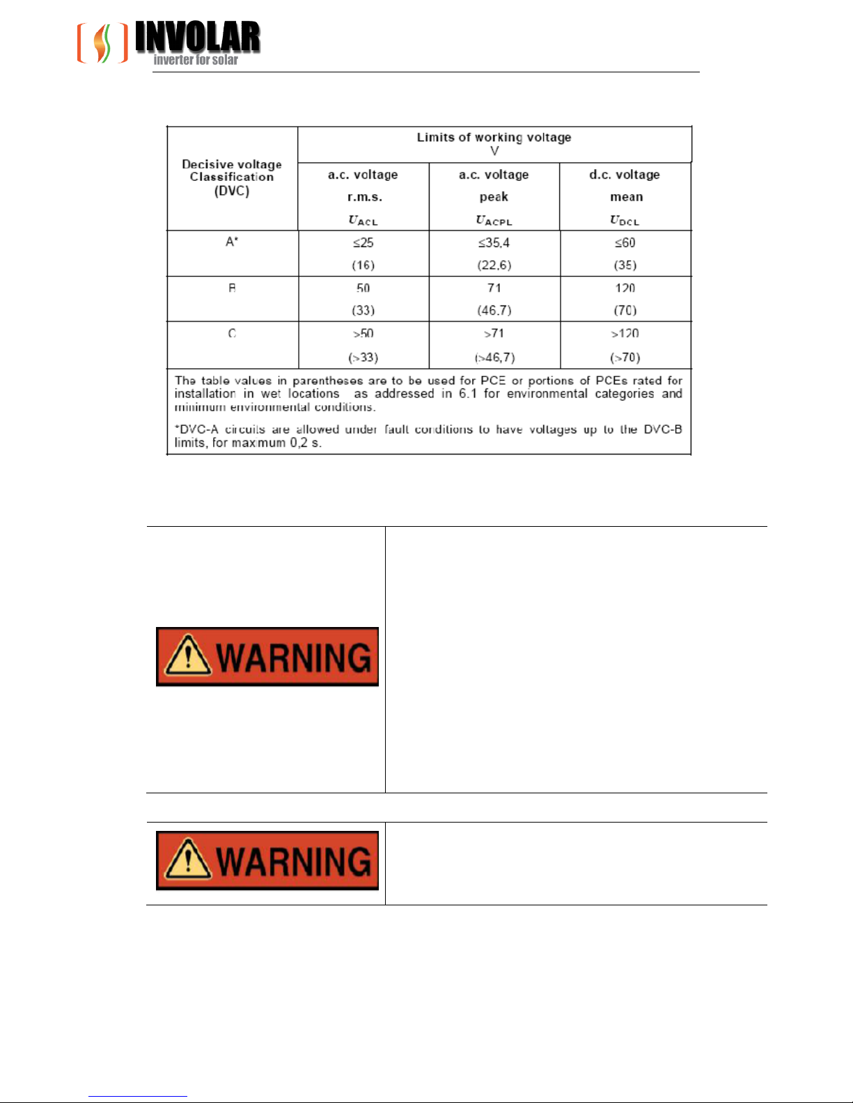
In accordance to EN 62109-1:2010, circuits complying with the requirements for
DVC-A are considered safe to touch, however, since the device is intended for
outdoor use and Vmax PV is rated 50V D.C, which exceeds maximum 35V DC limit for
DVC-A in WET LOCATION as below:
Version 4 Rev 1 Apr 2011 INVOLAR Corporation Ltd. (EUR)
13
Summary of the limits of the decisive voltage classes
The inverter and PV array are restricted for use in a CLOSED ELECTRICAL OPERATING AREA!
WARNING:
The grid connected inverter is intended to be used with
appropriate PV generator, switch gear, SPDs, distribution
board, electrical protection components and other
device to form complete end systems. Compliance with
safety regulations depends upon installing and
configuring inverter correctly, including using the
specified emergency stop device adjacent to solar
inverter. The unit must be installed only by professional
assemblers who are familiar with requirements for safety
and EMC. The assembler is responsible for ensuring that
the end product or system complies with all the relevant
laws in the country where it is to be used.
WARNING:
Fire hazard. Suitable for mounting on concrete or other
non-combustible surface only.
Version 4 Rev 1 Apr 2011 INVOLAR Corporation Ltd. (EUR)
14
WARNING:
Be aware that the input AC voltage of the
INVOLAR Micro-Inverter shall not exceed 50V,
or the higher voltage may cause permanent
damage to the device; it contains no user
serviceable and INVOLAR-Micro-Inverter
Warranty parts.
WARNING:
The device is not provided with ground-fault
detector/interrupter unit.
WARNING:
The device is not provided with automatic disconnecting
means – this device shall be provided with external
relaying protection in accordance with local codes and
local utility requirements.
CAUTION:
SAVE THESE INSTRUCTIONS– This manual contains
important instructions for Model MAC250 that shall be
followed during installation and maintenance of the
photovoltaic micro-inverter.
WARNING:
To reduce the risk of fire, do not connect to an ac load
center (circuit breaker panel) having multi-wire branch
circuits connected
CAUTION:
To reduce the risk of fire, connect only to a circuit
provided with 160 amperes maximum branch-circuit
over current protection in accordance with local codes
and local utility requirements.
WARNING!
The unit is to be installed so that it is not expected to be
contacted by persons!
Version 4 Rev 1 Apr 2011 INVOLAR Corporation Ltd. (EUR)
15
3.1 EC Directives
This chapter follows the requirements of the European Low Voltage Directives,
contains the safety instructions and conditions of acceptability for the endues system,
which you must follow when installing, operating and servicing the unit. If ignored,
physical injury or death may follow, or damage may occur to the unit. Read these
instructions before you work on the unit. If you are unable to understand the
Dangers, Warnings, Cautions or Instructions, contact the manufacturer or an
authorized service dealer before installing, operating and servicing the unit.
The Grid Connected Inverter meets the requirements stipulated in Low Voltage
Directive (LVD) 2006/95/EC and Electromagnetic Compatibility (EMC) Directive
2004/108/EC. The unit is tested based on:
EN 62109-1:2010;
EN 61000-6-1;
EN61000-6-2;
EN61000-6-3;
G83-1;
EN50438;
VDE0126-1-1:2006.
In case of installation in PV system, startup of the unit (i.e. start of designated
operation) is prohibited until it is determined that the full system meets the
requirements stipulated in the EC Directive (2006/95/EC, 2004/108/EC etc.).
The grid Connected Inverter leave the factory completely connecting device and
ready for connection to the mains and PV supply. The unit shall be installed in
accordance with national wiring regulations. Compliance with safety regulations
depends upon installing and configuring system correctly, including using the
specified wirings. The system must be installed only by professional assemblers who
are familiar with requirements for safety and EMC. The assembler is responsible for
ensuring that the end system complies with all the relevant laws in the country
where it is to be used.
The individual subassembly of the system shall be interconnected by means of the
wiring methods outlined in national/international regulations but not limited to the
BS7671 Requirements/ VDE regulation 0107.
WARNINGS
The device is not provided with ground-fault detector/interrupter
unit.
WARNINGS
The device is not provided with automatic disconnecting means –
this device shall be provided with external relaying protection in
accordance with local codes and local utility requirements.
[Use Condition]
 Loading...