

Invitrogen PowerEase 500, PowerEase 500 EI8600, PowerEase 500 EI8700, PowerEase 500 EI8675 Instructions For Use Manual

Artisan Technology Group is your source for quality
new and certied-used/pre-owned equipment
• FAST SHIPPING AND
DELIVERY
• TENS OF THOUSANDS OF
IN-STOCK ITEMS
• EQUIPMENT DEMOS
• HUNDREDS OF
MANUFACTURERS
SUPPORTED
• LEASING/MONTHLY
RENTALS
• ITAR CERTIFIED
SECURE ASSET SOLUTIONS
SERVICE CENTER REPAIRS
Experienced engineers and technicians on staff
at our full-service, in-house repair center
WE BUY USED EQUIPMENT
Sell your excess, underutilized, and idle used equipment
We also offer credit for buy-backs and trade-ins
www.artisantg.com/WeBuyEquipment
REMOTE INSPECTION
Remotely inspect equipment before purchasing with
our interactive website at www.instraview.com
LOOKING FOR MORE INFORMATION?
Visit us on the web at www.artisantg.com for more
information on price quotations, drivers, technical
specications, manuals, and documentation
Contact us: (888) 88-SOURCE | sales@artisantg.com | www.artisantg.com
SM
View
Instra

PowerEase® 500
Power Supply
Version D
032202
IM-8634
PowerEase® 500 Power Supply
A programmable power supply for electrophoresis
Catalog nos. EI8600, EI8700, EI8675
Artisan Technology Group - Quality Instrumentation ... Guaranteed | (888) 88-SOURCE | www.artisantg.com
www.invitrogen.com
tech_service@invitrogen.com

ii
Artisan Technology Group - Quality Instrumentation ... Guaranteed | (888) 88-SOURCE | www.artisantg.com

Warning
Federal
Communications
Commission
Advisory
This equipment has been tested and found to comply with the limits for a Class
A digital device, pursuant to part 15 of the FCC rules. These limits are designed
to provide reasonable protection against harmful interference when the
equipment is operated in a commercial environment. This equipment
generates, uses, and can radiate radio frequency energy and, if not installed and
used in accordance with the instruction manual, may cause harmful
interference to radio communications. Operation of this equipment in a
residential area is likely to cause harmful interference in which case the user
will be required to correct the interference at their expense.
Changes or modifications not expressly approved by the party responsible for
compliance could void the user’s authority to operate the equipment.
iii
Artisan Technology Group - Quality Instrumentation ... Guaranteed | (888) 88-SOURCE | www.artisantg.com

iv
Artisan Technology Group - Quality Instrumentation ... Guaranteed | (888) 88-SOURCE | www.artisantg.com

Table of Contents
Warning.................................................................................................................................................................iii
Table of Contents...................................................................................................................................................v
Kit Contents ..........................................................................................................................................................vi
Description...........................................................................................................................................................vii
Safety Information................................................................................................................................................xi
Consignes De Securite ........................................................................................................................................xii
Sicherheits Anweisungen..................................................................................................................................xiii
Accessory Products............................................................................................................................................xiv
Introduction....................................................................................................................1
Overview................................................................................................................................................................ 1
Methods..........................................................................................................................3
Getting Started....................................................................................................................................................... 3
Operational Modes................................................................................................................................................ 4
Using PowerEase® 500.......................................................................................................................................... 5
Printing ................................................................................................................................................................. 12
Custom Methods ................................................................................................................................................. 13
Troubleshooting ..................................................................................................................................................16
Appendix ......................................................................................................................17
Warranty............................................................................................................................................................... 17
Run Conditions for Gels..................................................................................................................................... 18
Repair and Maintenance of PowerEase® 500................................................................................................... 19
Theory of Operation............................................................................................................................................ 20
Technical Service................................................................................................................................................. 21
v
Artisan Technology Group - Quality Instrumentation ... Guaranteed | (888) 88-SOURCE | www.artisantg.com
Kit Contents
Types of Kits
Kit Components
This manual is supplied with the following kits:
Kit Catalog no.
PowerEase® 500 Power Supply (100/120 Vac 50/60 Hz) EI8600
PowerEase® 500 Power Supply (220/240 Vac 50/60 Hz) EI8700
PowerEase® 500 Pre-Cast Gel System
includes PowerEase® 500, Temperature Monitoring Probe, XCell
SureLock™ Mini-Cell and XCell II™ Blot Module
EI8675
PowerEase® 500 Power Supply contains:
PowerEase
®
500 Power Supply 1 each
Instruction Manual 1 each
Extra Fuses 2 each
Power Cord (U.S., Canada, Europe, Taiwan and Japan) 1 each
Warranty Card 1 each
Temperature Probe (Optional) 1 each
See next page for specifications and detailed description of PowerEase
®
500
Power Supply.
To ensure safe, reliable operation, always operate the PowerEase® 500 Power
Supply in accordance with the manufacturer’s instructions. Always wear
protective gloves and safety glasses when working in a laboratory environment.
See safety information on pages xi-xiii.
Warranty information is provided on page 17.
vi
Artisan Technology Group - Quality Instrumentation ... Guaranteed | (888) 88-SOURCE | www.artisantg.com

Description
Specifications
Input Power
100/120 VAC 90-132V, 50/60 Hz, 100 watts at maximum load
Fuse One 1A/250V/AGC, fast blow fuse
220/240 VAC 198-264VAC, 50/60 Hz, 260 mA at maximum load
Fuses Two F1A/250V/5x20 mm fast blow fuses
Output Range 1-500 V (minimum step size 1 V)
1-500 mA (minimum step size 1 mA)
0.1-50 W (minimum step size 0.1 W)
Automatic crossover on reaching set limits.
Accuracy Voltage: ± 2% or ± 2 volts
Current: ± 2% or ± 2 mA
Wattage ± 2% or ± 0.2 watt
Drift < 1% in 8 hours after 30 minute warm-up
with constant supply voltage
Circuit Protection Open Circuit; Short Circuit; Thermal Protection
Over Voltage, Current, Wattage
Safety Load Detection
Thermal Shutoff (with optional temperature probe)
Isolated Floating Ground
Memory Control Non-volatile, up to 24 hours
Custom Methods Stored to RAM
Computer Interface RS232C
Display LCD, view area 114 x 64 mm
240 x 128 dots
Temperature Ambient 4-30°C
Dimensions 16.5 cm (w) x 18 cm (h) x 20.5 cm (d)
Weight 2.9 kg (6.4 lbs)
Environmental
Conditions ≤ 100% RH, 75 KPa-106 KPa
vii
Artisan Technology Group - Quality Instrumentation ... Guaranteed | (888) 88-SOURCE | www.artisantg.com
Continued on next page
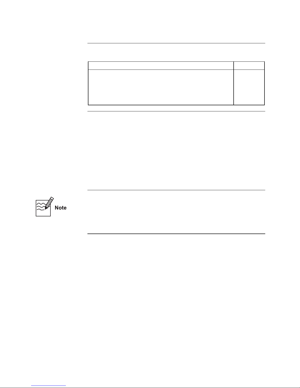
Description, Continued
Front View of
PowerEase
®
500
1
8
POWER
5
+
2
S
3
R
A
T
T
S
O
P
T
1. LCD Screen
2. Power Output Jacks, Positive (Red)
3. Power Output Jacks, Negative (Black)
4. Temperature Probe Jack
5. Functional Keys (Power, Start, Stop)
6. Directional Keys (Up, Down, Left, Right)
7. High Voltage LED
8. Power LED
P
SELECT
o
w
r
e
HIGH VOLTAGE
5
e
s
a
E
TEMP
7
0
0
6
4
viii
Artisan Technology Group - Quality Instrumentation ... Guaranteed | (888) 88-SOURCE | www.artisantg.com
Continued on next page
Description, Continued
Rear View of
PowerEase
®
500
Fan
Printer
Port
PRINTER
Power Entry Module
with On/Off
main power switch
RS232
RS232C
Communication
Port
Continued on next page
ix
Artisan Technology Group - Quality Instrumentation ... Guaranteed | (888) 88-SOURCE | www.artisantg.com
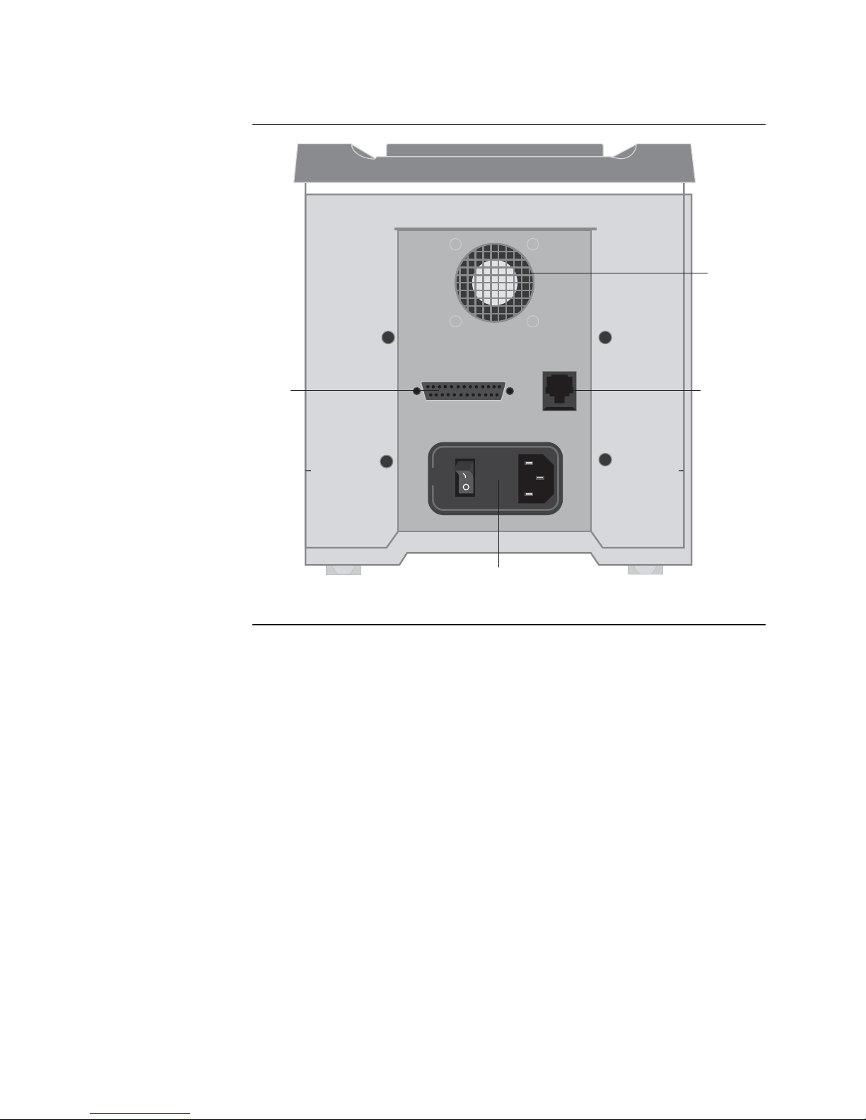
Description, Continued
Key Pad
Power button secondary On/Off switch for the high voltage components, fan, and LCD
SELECT
screen.
Start button used to start a selected method program.
Stop button used to end the selected method and to backup to a previous screen.
Select button used to select a menu choice and to move forward to the next applicable
screen.
Left directional button for moving left around the menu.
Right directional button for moving right around the menu.
Up directional button for moving up around the menu and to adjust numerical and
character values (higher).
Down direction button for moving down around the menu and to adjust numerical and
character values (lower).
x
Artisan Technology Group - Quality Instrumentation ... Guaranteed | (888) 88-SOURCE | www.artisantg.com
Safety Information
Avoiding
Electrical Shock
Avoiding Damage
to the Instrument
The PowerEase® 500 Power Supply produces high voltage outputs which are
electrically isolated from earth ground to reduce the risk of electrical shock to
the user. Observe the following guidelines to ensure safe operation of the unit.
The PowerEase
electrophoresis cells with shielded banana plugs thus minimizing potential
shock hazard to the user. Invitrogen does not recommend use of other
unshielded banana plugs.
To avoid electrical shock:
1. NEVER connect or disconnect wire leads from the power jacks when the
amber high voltage indicator light is on.
2. WAIT at least 5 seconds after stopping a run before handling output leads
or connected apparatus.
3. ALWAYS make sure hands and work area is clean and dry before making
any connections or operating the power supply.
4. ONLY connect the power supply to a properly grounded AC outlet.
1. For proper ventilation, leave at least 10 cm of space behind the instrument,
and at least 5 cm of space on each side.
2. Do not operate the power supply in high humidity environments (> 95%), or
where condensation can occur.
3. To avoid condensation after operating the power supply in a cold room, wrap
the unit in a plastic bag and allow at least 2 hours for the unit to equilibrate to
room temperature before removing the bag and operating the unit.
®
500 Power Supply has been designed for use with
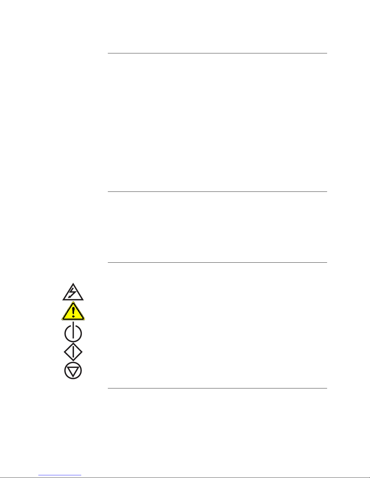
Symbols
The symbols used on the PowerEase® 500 Power Supply are explained below.
Used on the PowerEase® 500 Power Supply to indicate an area where a
potential shock hazard may exist.
Used on the PowerEase® 500 Power Supply to indicate a warning. Consult the
manual to avoid possible personal injury or instrument damage.
Used on the PowerEase
®
500 keypad to indicate the secondary Power button.
Used on the PowerEase
Used on the PowerEase
®
500 keypad to indicate the Start method button.
®
500 keypad to indicate the Stop method button.
xi
Artisan Technology Group - Quality Instrumentation ... Guaranteed | (888) 88-SOURCE | www.artisantg.com

Consignes De Securite
Consignes De
Securite
Pour éviter Tout
Choc électrique
Pour éviter
d’endommager
l’appareil:
Le PowerEase® 500 génère des courants de haut voltage; la construction du
système est faite suivant toutes précautions pour isoler l’utilisateur et éviter
tout choc électrique. Toutefois, il est impératif d’observer les consignes
suivantes pour éviter tout tisque lors de l’utilisation de l’appareil.
PowerEase
équipées avec des fiches banane protégées pour minimiser tout risque de choc
électrique. L’utilisation d’autres types d’équipments n’est pas recommandée
par Invitrogen et se fait aux risques et périls de l’utilisateur.
1. Ne jamais connecter ou déconnecter les cables des fiches quand l’indicateur
haut voltage est allumé..
2. Attendre un minimum de 5 secondes après avoir arrêté le courant avant de
manipuler le système.
3. Vérifier que vos mains sont séches et propres avant d’effectuer toute
connection.
4. Utiliser des prises de courant munies d’une connection à la terre.
1. Assurer une ventilation correcte, en laissant un minimum d’espace derrière
(10 cm) et sur les côtés (5 cm) de l’appareil.
2. N’utilisez pas le générateur dans un environement humide (> 95%) ou avec
des risques de condensation.
3. Pour éviter la condensation lors de l’utilisation de l’appareil en chambre
froide, enveloppez-le dans une poche plastique et laisser l’appareil
s’équilbrer à la température ambiante avant de retirer le sac et de l’utiliser.
®
500 est destiné à être utilisé avec des curves d’electrophorèse
Signification des pictogrammes
Sur le PowerEase® 500, signale les zones où un risque de choc électrique peut
exister.
Sur le PowerEase® 500, signale un risque potentiel pour l’utilisateur ou pour
l’equipement. Veuillez consulter le mode d’emploi.
Sue le panneau du PowerEase
Sur le panneau du PowerEase
Sur le panneau du PowerEase
®
500; bouton d’alimentation secondaire.
®
500; permet de démarrer une méthode.
®
500; bouton d’interruption.
xii
Artisan Technology Group - Quality Instrumentation ... Guaranteed | (888) 88-SOURCE | www.artisantg.com

Sicherheits Anweisungen
Sicherheits
Anweisungen
So verhindern Sie
eine Gefährdung
durch
Stromschlag
Das PowerEase® 500 Stromversorgungsgerät produziert GleichstromHochspannung, die elektrisch getrennt ist vom Erdleiter, um das Risiko des
Benutzers für einen Stromschlag zu minimieren. Trotzdem sollten folgende
Sicherheitsrichtlinien beachtet werden, damit ein einwandfreier Betrieb des
Gerätes gewährleistet ist.
Das PowerEase
Elektrophoresezellen mit isolierten Bananen-Schutzkontaktsteckern. Somit ist
eine Gefährdung durch Stromschlag bei sachgerechter Benutzung ausge
schlossen. Die Verwendung von anderen, ungeschützten Bananensteckern
geschieht auf Risiko des Benutzers und Invitrogen rät ausdrücklich davon ab.
1. Stecken (oder ziehen) Sie niemals Kabel in die Stromausgangsbuchsen am
Gerät, wenn das gelbe Licht (Hochspannungs-Indikator) am
Bedienungsfeld leuchtet.
2. Warten Sie mindestens 5 Sekunden nach Beendigung und Ausschalten
eines Laufs, bevor Sie die Anschlubkabel der Zelle herausziehen.
3. Achten Sie darauf, dab die Arbeitsplatzumgebung der Zelle sauber und
rocken ist. Sie sollten niemals mit nassen Händen Gerät, Kabel oder
Steckverbindungen anfassen.
4. Schlieben Sie das PowerEase
230V Strombuchse an.
®
500 ist entwickelt worden für den Betrieb von
®
500 nur an eine einwandfrei geerdete 220-
Um Beschädigung
des Geräts zu
vermeiden
Symbolerklärung
1. Achten Sie auf wenigstens 10 cm Platz hinter und 5 cm neben dem Gerät,
um seine eingebaute Kühlventilation nicht zu beeinträchtigen.
2. Verwenden Sie das Gerät nicht in Räumen mit hoher Luftfeuchtigkeit
(>95%) oder wo es Wasserdampfkondensation ausgesetzt ist.
3. Ist das Gerät in einem Kühlraum verwendet worden, und soll es nach der
Benutzung wieder unter Normaltemperaur arbeiten, ist es vor der
Umsetzung in eine Kunststoffhülle zu packen. Es soll mindestens 2 Stunden
darin auf die neue Umgebungstemperatur angepasst werden, bevor die
Hülle entfernt und das Gerät wieder in Betrieb genommen wird.
Weist auf eine Zone hin, wo Gefährdung durch Stromschlag besteht.
Lesen Sie die Bedienungsanleitung, um Verletzungen oder Beschädigung des
Gerätes zu vermeiden.
1st der 2. Bertiebsschalter auf dem PowerEase
Start—Knopf auf dem Bedienungsfeld für eine programmierte Methode.
Stop—Knopf auf den Bedienungsfeld für einen Elektophorese—Lauf.
®
500—Bedienungsfeld.
xiii
Artisan Technology Group - Quality Instrumentation ... Guaranteed | (888) 88-SOURCE | www.artisantg.com

Accessory Products
Additional
Products
Additional products that can be used with the PowerEase® 500 Power Supply
or replacement parts for PowerEase
from Invitrogen. For more information, contact Technical Service (see page 21)
or visit our Web site at www.invitrogen.com.
Temperature Monitoring Probe 1 EI8644
RS232 Cable and Adaptor 1 EI8663
Fuses 1A/250V/3AGL Fast Blow (100-120VAC units) 2 EI8670
Fuses F1A/250V/5x20mm Fast Blow (220-240V units) 4 EI8671
XCell SureLock™ Mini-Cell 1 unit EI0001
XCell II™ Blot Module 1 unit EI9051
®
500 Power Supply are available separately
Product Quantity Catalog no
xiv
Artisan Technology Group - Quality Instrumentation ... Guaranteed | (888) 88-SOURCE | www.artisantg.com

Overview
Introduction
Features of
PowerEase® 500
Introduction
The PowerEase® 500 Power Supply is a microprocessor-controlled power supply
for electrophoresis of pre-cast and hand-poured mini-gels. The power supply is
designed to simplify electrophoresis by combining high performance and
programming flexibility with ease of use when running mini-gel and blotting
applications.
The PowerEase
you need to think only about the electrical parameters and limits for a single gel.
This manual describes the setup and operation of PowerEase
including important information on safety and maintaining the unit.
The important features of PowerEase® 500 Power Supply are listed below:
• Large LCD display allows electrical parameters to be displayed in either
graphical or numerical formats
• Eight pre-programmed methods for running and blotting Novex
mini-gels
• Four custom methods for running your custom applications
• Simple three step operating procedure to start running or blotting Novex
pre-cast gels
• Microprocessor control provides highly accurate electrical outputs resulting
in exceptional blotting capability
• Parallel port for printing experimental results to most printers
• Optional Temperature Probe to continuously monitor the buffer temperature
and shut the unit down in the event of overheating
• Two sets of output jacks allows electrophoresis of multiple mini-cell units in
constant voltage, current, or watts
®
500 Power Supply is designed around the single gel concept:
®
500 Power Supply
®
pre-cast
®
1
Artisan Technology Group - Quality Instrumentation ... Guaranteed | (888) 88-SOURCE | www.artisantg.com
Continued on next page

Overview, Continued
Flowchart
The flowchart below describes the various screens displayed on the PowerEase®
500 Power Supply and the keypad buttons (Start, Stop or Select) used to
navigate through the screens.
Power ON
Start-Up Screen
Start/Select
Gel Method Screen
Select
Gel Quantity Screen
Method Edit Screen
Method Run Large Display
Select
Method Run Large Display
StopStart
Previous Screen
Method Run Graphic Display
Start
Select, once Select, twice
Method Run Graphic Display
Stop
Previous Screen
Select
Method Run/Edit Screen
Select, onceSelect, twice
Method Run Large Display
2
Artisan Technology Group - Quality Instrumentation ... Guaranteed | (888) 88-SOURCE | www.artisantg.com

Getting Started
Installing
PowerEase
®
500
Installing an
Optional Printer
1. Place the PowerEase® 500 Power Supply on a level bench. Keep the area
2. Position the unit properly such that the On-Off switch and the power cord
3. Check the label located near the power entry module to ensure that the unit
The PowerEase® 500 Power Supply has a DB25 parallel connector located on the
rear of the unit. This allows the PowerEase
of your electrophoresis results in ASCII format to most commonly available
printers.
Use the following steps to install a printer:
1. Using a parallel printer cable, connect the male DB25 end of the printer cable
2. Connect the opposite end of the cable into the appropriate connector on the
Methods
around the power supply clear to ensure proper ventilation of the unit.
attachment module located on the rear of the unit are easily accessible.
is of the proper local voltage. Attach the power cord to the power entry
module. Use only properly grounded AC outlets.
®
500 Power Supply to print a report
into the port marked “Printer” located on the rear of the PowerEase
Power Supply.
printer. Refer the user manual of your printer for instructions on connecting
the cable to the printer.
®
500
Installing an
Optional
Temperature
Probe
If you have ordered the Temperature Monitoring Probe, follow the instructions
below to install the probe:
1. Unpack the Temperature Monitoring Probe and inspect for any possible
damage to the wire or connector which may have occurred during shipping.
2. Plug the connector end of the Temperature Monitoring Probe into the port
located at the front lower right corner of the PowerEase
®
500 Power Supply
marked “TEMP”.
3. Place the opposite end of the Temperature Monitoring Probe with the bluecolored bead into an electrophoresis cell buffer chamber to display
temperature on the LCD screen of the PowerEase
can bent the wire, but avoid crimping or pinching the wire. Temperature will
be displayed at all times even when the PowerEase
®
500 Power Supply. You
®
500 Power Supply is
stopped.
3
Artisan Technology Group - Quality Instrumentation ... Guaranteed | (888) 88-SOURCE | www.artisantg.com

Operational Modes
Introduction
Voltage Limiting
Current Limiting
The PowerEase® 500 Power Supply is capable of operating at limiting voltage,
limiting current, and limiting power. We recommend operating the PowerEase
500 Power Supply at limiting voltage for most applications. See below for more
details.
The recommended setting for operating the PowerEase® 500 Power Supply is
voltage limited. For most electrophoresis methods, resistance increases
throughout the run. Using voltage limiting provides the following advantages:
• Current and watts decrease throughout the run, providing a natural safety
margin.
• The same voltage setting can be used regardless of the number or thickness
of gels being electrophoresed.
Discontinuous buffer systems and, to a lesser extent continuous systems,
increase resistance during the run. If you use the current limiting setting on the
PowerEase
to satisfy Ohm’s law (V=IR, see page 20). If no voltage limit is set and a local
fault condition occurs, such as a poor connection, very high local resistance
may cause the voltage to increase to a maximum of the power supply. This will
lead to local overheating and damage to the electrophoresis cell or create unsafe
conditions.
When running under constant current conditions, set a voltage limit on the
power supply at or slightly above the maximum expected voltage.
®
500 Power Supply, the voltage will increase as resistance increases
®
Wattage Limiting
If power is constant, voltage will increase and current will decrease during a
run, but the total amount of heat generated by the system will remain constant
throughout the run. However, locally high resistance can cause a high
proportion of the total heat to be generated over a small distance. This can
damage the electrophoresis cell and/or gel(s).
If operating at wattage limiting, set the voltage limiting to slightly above the
maximum expected for the run.
4
Artisan Technology Group - Quality Instrumentation ... Guaranteed | (888) 88-SOURCE | www.artisantg.com

Using PowerEase® 500
Introduction
Starting
PowerEase® 500
You can operate the PowerEase® 500 Power Supply immediately after
installation using three simple steps (see below). For programming custom
settings, see page 13.
1. Plug the power cord of the PowerEase® 500 Power Supply into an available
electrical outlet rated at the appropriate electrical values for the power
supply.
2. Turn on the main power switch located on the rear of the PowerEase
Power Supply (see page ix for rear view of PowerEase
Always leave this switch in the ON position to keep the back-up battery fully
charged.
3. Press the Power button located on the keypad (see page x for a figure of the
keypad). This Power button is a secondary power button and does not
actually shut the instrument down, but shuts down the high voltage, fan,
and LCD screen. When powered back up, the LCD screen will revert to the
same screen as when the secondary power was shut off.
4. A Start-Up screen will appear (see next page).
To avoid condensation, the main power switch located on the rear of the unit
should be left on between use during operation in a cold room or in high
humidity environments.
®
®
500 Power Supply).
500
Operating
PowerEase
®
500
A simple operating procedure of the PowerEase® 500 Power Supply is provided
below. For more details on the different screens and custom methods, see pages
5-13.
1. Turn on the PowerEase
®
500 Power Supply.
2. Press Select once the Start-Up screen appears.
3. Select your gel type from the Gel Method screen.
4. Choose the number of gels to be electrophoresed from the Gel Quantity
screen.
5. Press the Start button to begin electrophoresis.
Note: To reset the PowerEase
®
500 Power Supply, press the Stop button.
The maximum number of Novex® mini-gels that can be electrophoresed at the
same time using PowerEase
®
500 Power Supply and the XCell SureLock™ Mini-
Cell is listed below:
Gel Type Number of Gels
Novex
NuPAGE
NuPAGE
®
Tris-Glycine Gels 10 gels
®
Novex Tris-Acetate Gel 6 gels
®
Novex Bis-Tris Gels 2 gels
Novex® Tricine Gels 4 gels
Novex
®
TBE-Urea gels 10 gels
5
Artisan Technology Group - Quality Instrumentation ... Guaranteed | (888) 88-SOURCE | www.artisantg.com
Continued on next page

Using PowerEase® 500, Continued
Start-Up Screen
Gel Method
Screen
The Start-Up screen is the first screen to appear after pressing the Power button
on the keypad.
Press the Select button to advance to the Gel Method screen.
Note: After first use, the last screen previously in use will appear after shutting
the power off and back on again.
The Gel Method screen (see figure below) allows you to select from a choice of
eight pre-programmed methods for Novex
methods.
1. Use the directional arrow buttons to navigate through the menu.
2. Press the Select button to choose the method. You will advance to the Gel
Quantity screen (see next page) if a pre-programmed method is chosen, or to
the Custom Method Option screen (see page 13) if a user defined method is
selected.
Note: The pre-programmed method durations are set to the shortest run time per
gel type, or buffer level and buffer strength to prevent over-running a gel.
Different percentage gels within a single gel type can cause a gel to take longer to
run. Additional time can be added to the pre-programmed method before,
during, and after a run (see page 11). The estimated durations for different
percentage Novex
®
mini-gels are listed on page 18.
®
mini-gels or four user-defined
6
Artisan Technology Group - Quality Instrumentation ... Guaranteed | (888) 88-SOURCE | www.artisantg.com
Tris-Gly Gel
TBE Gel
IEF Gel
Western Blot
User-Custom1
User-Custom3
SELECT to continue
Tricine Gel
TBE-Urea Gel
NuPAGE Gel
NuPAGE Blot
User-Custom2
User-Custom4
and moves cursor
Continued on next page

Using PowerEase® 500, Continued
Gel Quantity
Screen
The Gel Quantity screen (see figure below) allows you to scale the preprogrammed method’s current and power values by the number of gels that are
to be run.
1. Use the Up and Down arrows on the keypad to increase or decrease the
number of gels from 1 to the maximum allowable quantity of gels which can
be run for the specified method.
2. Press the Start button to begins the electrophoresis. The Method Run Large
Display screen will be displayed.
3. If you need to edit any electrophoresis parameters, press the Select button to
advance to the Method Edit screen (see page 10).
The Stop button returns you to the Gel Method screen (or the Custom Method
Options screen if a custom method is in use).
If the number of gels selected causes the current to be scaled such that the
PowerEase
error message “Power Limit Reached” will be displayed. Similarly, if the current
exceeds 500 mA, an error message “Current Limit Reached” will be displayed.
Change the number of gels appropriately to continue electrophoresis.
Note: Avoid changing the number of gels during the run, unless gels are
removed during the run. If you would prefer to see the total output parameters,
leave the gel number at “1” before starting.
®
500 Power Supply maximum power limit of 50 watts is exceeded, an
Tris-Glycine Gel
Number of
Gels to be run:
START begins; SELECT edits
2
adjust number of gels
Continued on next page
7
Artisan Technology Group - Quality Instrumentation ... Guaranteed | (888) 88-SOURCE | www.artisantg.com

Using PowerEase® 500, Continued
Method Run Large
Display
The Method Run Large Display screen (see figure below) is displayed after the
Start button is pressed from the Gel Quantity screen or the Method Edit
screen. This screen displays the status of the method during a run in an easy to
read format. The screen displays:
• Selected Method
• Status (running or paused)
• Number of Gels
• Run Condition (Limiting Parameters)
• Actual Voltage and Current (large display)
• Step Time Remaining
• Present Step Number
• Actual Wattage (small display)
• Detected Temperature (if installed)
Pressing the Select button once takes you to the Method Run Graphic Display
screen (see next page) and to the Method Run/Edit screen (see page 11) if
pressed twice.
The Stop button pauses the run if pressed once, stops the method if the method
is already in the paused state and takes you to the Method Edit screen.
To resume, press the Start button.
Tris-Glycine Gel
Voltage is constant
125V
30mA
SELECT views; STOP pauses
RUNNING
Time
Left: 0:07
Step:
Power:
Temp:
2
Gels
1
2W
24oC
Continued on next page
8
Artisan Technology Group - Quality Instrumentation ... Guaranteed | (888) 88-SOURCE | www.artisantg.com

Using PowerEase® 500, Continued
Method Run
Graphic Display
The Method Run Graphic Display screen (see figure below) is displayed after
the Select button is pressed from the Method Run Large Display screen. This
screen displays the status of the method during a run in a graphical format. The
screen displays:
• Selected Method
• Status (running or paused)
• Present Run Time
• Voltage, Current, and Wattage (applied during the run)
• Run Condition (Limiting Parameter)
The Select button takes you to the Method Run/Edit screen (see page 11).
The Stop button pauses the run if pressed once, stops the method if pressed
twice and takes you to the Method Edit screen.
To resume, press the Start button.
IEF Gel
RUNNING
500V
c
u
r
r
e
n
t
v
o
l
t
s
p
o
w
e
r
6mA
2:07
2W
SELECT views; STOP pauses
Continued on next page
9
Artisan Technology Group - Quality Instrumentation ... Guaranteed | (888) 88-SOURCE | www.artisantg.com

Using PowerEase® 500, Continued
Method Edit
Screen
The Method Edit screen (see figure below) is displayed after the Select button is
pressed from the Gel Quantity screen. The Method Edit screen allows you to
edit the following method parameters:
• Step Duration
The maximum step duration is 24 hours. If the duration is set to zero, the
step will be deleted and all following steps will be moved up. If you set an
empty step to non-zero, the voltage, current, and wattage settings from the
previous line will be copied.
• Step Voltage Limit
• Step Current Limit
• Step Power Limit
• Load Check State
The Load Check state is either ON or OFF, and determines whether or not
the PowerEase
®
500 Power Supply unit will detect ‘No Load’ conditions. The
default value for Load Check is ON and is the recommended state.
• Gel Quantity
The gel quantity limit determines the maximum voltage, current, and
wattage for the step. Values must be in the range of 1 to 500 volts, 1 to
500 mA, and 0.1 to 50 watts for one gel (the values for current and watts will
be reduced if multiple gels are selected).
If you have changed a pre-programmed method, the method will always run as
edited until you cycle back to the Gel Method screen. At this point the preprogrammed method will revert to the default parameters.
To edit the parameters on this screen:
1. Press the Left or Right arrow buttons to move the cursor between different
fields. As the cursor moves from field to field, a status message on LCD
display is updated to show the affected parameters if changes are made.
2. Use the Up and Down buttons to adjust field values.
3. Press the Start button to begin the run and change the display to the monitor
state. The Stop button takes you to the Gel Quantity screen (see page 7).
10
Artisan Technology Group - Quality Instrumentation ... Guaranteed | (888) 88-SOURCE | www.artisantg.com
Tris-Glycine Gel
Step Time Limits
1
2
3
START begins; STOP for prior
1:30
moves cursor
adjusts run time
125V
Load Check: ON
24oC
100 mA 18.0W
Continued on next page

Using PowerEase® 500, Continued
Method Run/Edit
Screen
The Method Run/Edit screen (see figure below) is displayed after the Select
button is pressed from the Method Run Large Display screen or the Method
Run Graphic Display screen. This screen displays the status of the method
during a run and allows you to edit parameters during the run for the current
step displayed on this screen.
The screen displays:
• Selected Method
• Status (running or paused)
• Number of Gels
• Total Time Elapsed
• Run Condition (limiting parameter or error condition if detected)
• Detected Temperature (if probe is installed)
• Present Step Number
• Present Parameter Set Points
• Step Time Elapsed
• Actual Voltage, Current and Wattage
Make the appropriate change using the directional arrow keys and press the
Start button.
The Select button takes you to the Method Run Large Display if pressed once,
and to the graphic display if pressed twice.
The Stop button pauses the run if pressed once and stops the method if the
method is already paused.
11
Artisan Technology Group - Quality Instrumentation ... Guaranteed | (888) 88-SOURCE | www.artisantg.com

Printing
Print Screen
PowerEase® 500 Power Supply is equipped with a parallel port, allowing you to
print your electrophoresis report.
1. If you wish to print a report, you need to connect the PowerEase
Supply to a printer. See page 3 for Installing an Optional Printer.
2. After a run is completed (time left must be zero), the message “START prints
STOP quits” is displayed at the bottom of the screen.
3. Press the Start button to print a report reflecting voltage, current, watts, and
temperature changes which occurred during the run.
An example of a report is shown below:
Method name: IEF Gel
Run Data:
Time Voltage Current Power Resistance Temp
Step hh:mm V mA W Kohms °C
1 0:05 100 3.7 0.4 27.31 24
0:10 100 3.2 0.4 32.55 24
0:15 100 2.8 0.3 39.23 24
0:20 100 2.3 0.2 45.71 23
0:25 100 2.1 0.1 54.33 23
®
500 Power
12
Artisan Technology Group - Quality Instrumentation ... Guaranteed | (888) 88-SOURCE | www.artisantg.com

Custom Methods
Custom Method
Options Screen
The Custom Method Options screen (see figure below) allows you to program a
custom method. The screen displays the following menu choices:
• Edit or Run Method
• Save Method
• Change Method name
• Reset Method
1. Use the Up and Down arrow buttons to choose from the menu items.
2. Press the Select button to select the current menu choice.
The Stop button returns you to the Gel Method screen (see page 6).
Menu for User-Custom1
Edit or Run Method
Save Method
Change Method name
Reset Method
SELECT chooses; STOP for prior
moves cursor
Edit or Run
Method
The Edit or Run Method option displays the Gel Quantity screen (see figure
below) for the pre-programmed methods. Enter the number of gels to be run and
press Start to begin the run.
User-Custom1
Number of
Gels to be run:
1
adjust number of gels
START begins; SELECT edits
If you need to edit run parameters, press Select to display the Method Edit
screen (see figure below).
User-Custom1
Step Time Limits
1
0:30
2
0:30
3
1:00
100V
200V
500V
Load Check: ON
25mA 2.5W
50mA
110mA
9.0W
50.0W
24oC
13
Artisan Technology Group - Quality Instrumentation ... Guaranteed | (888) 88-SOURCE | www.artisantg.com
moves cursor
adjusts run time
START begins; STOP for prior
Continued on next page

Custom Methods, Continued
Save Method
Change Method
Name
The Save Method option saves any changes made to the method during the
previous editing session. It is not necessary to save the method before the
method is run. Method is saved to RAM.
The Change Method Name screen (see figure below) allows you to change a
custom method user name. The screen displays the current default custom
method user name (i.e. User-Custom1) and a new name field that is used to
change the default method user name.
1. Use the Left or Right arrow buttons to change the current character (only
capital letters, numbers 0 to 9, and a few other characters such as “-” and “\”
are available).
2. Press the Start button to delete the character directly under the cursor and all
remaining characters to the right of the cursor.
3. Press the Select button to accept the new name as the name of the method
and return you to the Custom Method Options screen. The Stop button
abandons changing the method name and returns you to the Custom
Method Options screen.
Change Method Name
Old Name:
User-Custom1
ZYMOGRAMNew Name:
START erases remaining chars
SELECT to accept; STOP exits
changes letter
moves cursor
Continued on next page
14
Artisan Technology Group - Quality Instrumentation ... Guaranteed | (888) 88-SOURCE | www.artisantg.com

Custom Methods, Continued
Reset Method
The Reset Method screen returns all method parameters including the custom
name back to the original default parameters.
1. To reset, choose “Yes” with the Left button and then press the Select
button.
2. The custom method is cleared and the Gel Method screen is displayed.
Choosing “No” and pressing the Select button, or pressing the Stop button
returns you to the Custom Method Options screen.
User-Custom1
Method will be reset to
default values. Is this OK?
Yes
moves cursor
SELECT choice
NO
15
Artisan Technology Group - Quality Instrumentation ... Guaranteed | (888) 88-SOURCE | www.artisantg.com

Troubleshooting
Introduction
Problem Cause Solution
The LCD screen remains
blank and the fan does not
come on when the main
power is turned on
Display shows PAUSE
and Load Error
Display shows PAUSE
and Hardware Error
Display shows PAUSE and
Temperature Error (if
temperature probe is
connected)
“Current Limit Reached” is
displayed on the Gel
Quantity screen
“Power Limit Reached” is
displayed on the Gel
Quantity screen
Review the information in the table below to troubleshoot your experimental
results.
Power cord not connected or the
fuse has blown
Secondary power off
Electrophoresis cell(s) are not
connected, are disconnected
during the run, or there is a
broken connection in the
electrophoresis cell
High resistance due to tape left on
a pre-cast gel, incorrect buffer
concentration, or incorrect buffer
volumes in the electrophoresis cell
--
Buffer temperature exceeds the
preset temperature limit
Number of gels selected exceeds
the set current limit
Number of gels selected exceeds
the set power limit
Check power cord connections at
both ends or replace the fuse (see
page 19).
Press the Power button on the
keypad.
Check the connections to the power
supply and on your electrophoresis
cell to make sure the connection is
intact.
Press the Stop button.
Correct the condition by making
sure the tape is removed from the
pre-cast gel, buffers are prepared
correctly, and the recommended
volume of buffer is added to the
electrophoresis cell.
Restart the method.
Reset unit by holding front panel
Power button down while switching
rear power switch off and then on
again. Release front Power button.
Check the run conditions for the
correct current and power settings.
Make sure the buffer is prepared
correctly.
Raise the temperature limit.
Number of gels is limited by the
maximum current available.
Decrease the number of gels or
change the current settings.
Number of gels is limited by
maximum power available.
Decrease the number of gels or
change the power settings.
16
Artisan Technology Group - Quality Instrumentation ... Guaranteed | (888) 88-SOURCE | www.artisantg.com

Warranty
PowerEase® 500
Power Supply
Warranty
Appendix
Invitrogen warrants that this product will be free from defects in material and
workmanship for a period of one (1) year from date of purchase. If a defect is
present, Invitrogen will, at its option, repair, replace, or refund the purchase
price of this product at no charge to you, provided it is returned during the
warranty period. This warranty does not apply if the product has been damaged
by accident, abuse, misuse, or misapplication, or from ordinary wear and tear.
For your protection, items being returned must be insured against possible
damage or loss. This warranty shall be limited to the replacement of defective
products. IT IS EXPRESSLY AGREED THAT THIS WARRANTY WILL BE IN
LIEU OF ALL WARRANTIES OF FITNESS AND IN LIEU OF THE WARRANTY
OF MERCHANTABILITY.
17
Artisan Technology Group - Quality Instrumentation ... Guaranteed | (888) 88-SOURCE | www.artisantg.com

Run Conditions for Gels
Introduction
4% Tris-Glycine 125 V 90 minutes
6% Tris-Glycine 125 V 95 minutes
8% Tris-Glycine 125 V 100 minutes
10% Tris-Glycine 125 V 105 minutes
12% Tris-Glycine 125 V 110 minutes
14% Tris-Glycine 125 V 110 minutes
16% Tris-Glycine 125 V 115 minutes
18% Tris-Glycine 125 V 120 minutes
4-12% Tris-Glycine 125 V 105 minutes
4-20% Tris-Glycine 125 V 110 minutes
8-16% Tris-Glycine 125 V 105 minutes
10-20% Tris-Glycine 125 V 120 minutes
10% Tricine 125 V 70 minutes
16% Tricine 125 V 90 minutes
10-20% Tricine 125 V 75 minutes
10% Zymogram 125 V 100 minutes
12% Zymogram 125 V 110 minutes
4-16% Zymogram 125 V 100 minutes
6% TBE 100 V 65 minutes
10% TBE 100 V 100 minutes
20% TBE 200 V 105 minutes
4-20% TBE 200 V 70 minutes
6% TBE-Urea 180 V 45 minutes
10% TBE-Urea 180 V 60 minutes
15% TBE-Urea 180 V 80 minutes
IEF pH 3-7, Step 1 100 V 60 minutes
IEF pH 3-7, Step 2 200 V 60 minutes
IEF pH 3-7, Step 3 500 V 30 minutes
IEF pH 3-10, Step 1 100 V 60 minutes
IEF pH 3-10, Step 2 200 V 60 minutes
IEF pH 3-10, Step 3 500 V 30 minutes
NuPAGE® Novex 10% Bis-Tris with MES SDS Running Buffer 200 V 35 minutes
NuPAGE® Novex 4-12% Bis-Tris with MES SDS Running
Buffer
NuPAGE® Novex 10% Bis-Tris with MOPS SDS Running
Buffer
NuPAGE® Novex 4-12% Bis-Tris with MOPS SDS Running
Buffer
NuPAGE® Novex 7% Tris-Acetate 150 V 60 minutes
NuPAGE® Novex 3-8% Tris-Acetate 150 V 70 minutes
The estimated run duration for Novex® 1.0 mm thick mini-gel is listed below. A
1.5 mm thick gel will take 5-10 minutes longer than similar 1.0 mm thick gel.
Gel Type Voltage Approximate Duration
200 V 35 minutes
200 V 50 minutes
200 V 50 minutes
18
Artisan Technology Group - Quality Instrumentation ... Guaranteed | (888) 88-SOURCE | www.artisantg.com

Repair and Maintenance of PowerEase® 500
Introduction
On Receiving the
Instrument
For a Problem
Requiring Service
Replacing the
Fuse
The PowerEase® 500 Power Supply requires no periodic maintenance program
with the exception of an occasional wipe-down of the instrument to remove salt
deposits which may built up over time.
Examine the unit carefully for any damage inflicted during transit. Any damage
claims must be filed with the carrier. The warranty does not cover in-transit
damage.
1. Check the troubleshooting section on the previous page.
2. Call Technical Service (see page 21).
3. If the unit must be shipped back for repair, contact Invitrogen or the
distributor for a Return Authorization Number and shipping instructions. The
unit will be repaired as quickly as possible and returned to you.
Extra fuses are supplied with PowerEase® 500 Power Supply. For additional
fuses, see page xiv for ordering information.
1. Turn off the main power switch at the rear of the PowerEase
Supply and detach the power cord from the rear of the PowerEase
Power Supply.
2. Open the fuse compartment located inside the Power Entry Module (see
page ix for rear view of the PowerEase
®
500 Power Supply) by inserting a
small flat blade screwdriver into the slot above the ON/OFF switch. Turn
the screwdriver to gently pry open the fuse compartment.
Note: The fuse compartment will not open with the power cord in place.
3. Pull the fuse holder out of the compartment and inspect the fuse. If the fuse
is burned or there is a break in the fuse element, replace the fuse with the
identical type fuse (see figure below).
4. Place the fuse holder(s) back into the compartment, making sure that the
arrow(s) on the fuse holder point in the same direction as the arrows on the
inside of the fuse compartment as shown in the figure below.
5. Snap the cover closed.
SLOT
SLOT
®
500 Power
®
500
100/120V UNIT
19
Artisan Technology Group - Quality Instrumentation ... Guaranteed | (888) 88-SOURCE | www.artisantg.com
ON/OFF SWITCH
FUSE HOLDER(S)
POWER CORD
CONNECTION
ON/OFF SWITCH
FUSE HOLDER(S)
POWER CORD
CONNECTION
220/240V UNIT

Theory of Operation
Power
Considerations
Resistance
Voltage
Electrophoresis is the migration of a charged particle under the influence of an
electrical field. The influence of various power supply output parameters (volts,
current and watts) is derived from two equations:
Voltage = Current x Resistance (V=IR)
Wattage = Current x Voltage (W=IV)
Resistance of the assembled electrophoresis cell is dependent on the
conductivity of the gel buffer, the thickness of the gel, and the number of gels
being run. Although the resistance is determined by the gel system, the
resistance can vary over the course of the run. For instance, in the Tris-Glycine
buffer system, the fast moving, highly conductive chloride ions in the gel are
gradually replaced by the slower moving, less conductive glycine ions from the
running buffer as the gel runs. As a result, the resistance of the gel increases as
the chloride/glycine front moves down the gel, and the current decreases.
The velocity in which an ion moves in an electric field will vary in proportion to
the field strength (Volts per unit distance). The higher the voltage the faster an
ion will move.
Current
Power
Current is a function of the number of ions passing a given cross-section of the
circuit at a given time. For a given gel/buffer system, at a given temperature,
current will vary in proportion to the field strength (voltage) and/or crosssectional area (number and/or thickness of the gels). Ions in solution and at a
given voltage will move faster as the temperature increases, increasing current.
Watts, or the rate of heat generated by the system, is a function of voltage and
current (W=IV). For a given gel system if either voltage is doubled, watts will
also double (as V=IR, and R is a “constant” determined by the gel system).
20
Artisan Technology Group - Quality Instrumentation ... Guaranteed | (888) 88-SOURCE | www.artisantg.com

Technical Service
World Wide Web
Contact Us
Corporate Headquarters:
Invitrogen Corporation
1600 Faraday Avenue
Carlsbad, CA 92008
USA
Tel: 1 760 603 7200
Tel (Toll Free): 1 800 955 6288
Fax: 1 760 602 6500
E-mail:
tech_service@invitrogen.com
Visit the Invitrogen Web Resource using your World Wide Web browser. At the
site, you can:
• Get the scoop on our hot new products and special product offers
• View and download vector maps and sequences
• Download manuals in Adobe
• Explore our catalog with full color graphics
• Obtain citations for Invitrogen products
• Request catalog and product literature
Once connected to the Internet, launch your web browser (Netscape 3.0 or
newer), then enter the following location (or URL):
...and the program will connect directly. Click on underlined text or outlined
graphics to explore. Don't forget to put a bookmark at our site for easy reference!
For more information or technical assistance, please call, write, fax, or email.
Additional international offices are listed on our Web page (www.invitrogen.com).
®
Acrobat® (PDF) format
http://www.invitrogen.com
Japanese Headquarters:
Invitrogen Japan K.K.
Nihonbashi Hama-Cho Park
Bldg. 4F
2-35-4, Hama-Cho, Nihonbashi
Tel: 81 3 3663 7972
Fax: 81 3 3663 8242
E-mail: jpinfo@invitrogen.com
European Headquarters:
Invitrogen Ltd
3 Fountain Drive
Inchinnan Business Park
Paisley PA4 9RF, UK
Tel: +44 (0) 141 814 6100
Fax: +44 (0) 141 814 6287
E-mail: eurotech@invitrogen.com
©1996-2002 Invitrogen Corporation. All rights reserved.
21
Artisan Technology Group - Quality Instrumentation ... Guaranteed | (888) 88-SOURCE | www.artisantg.com

Artisan Technology Group is your source for quality
new and certied-used/pre-owned equipment
• FAST SHIPPING AND
DELIVERY
• TENS OF THOUSANDS OF
IN-STOCK ITEMS
• EQUIPMENT DEMOS
• HUNDREDS OF
MANUFACTURERS
SUPPORTED
• LEASING/MONTHLY
RENTALS
• ITAR CERTIFIED
SECURE ASSET SOLUTIONS
SERVICE CENTER REPAIRS
Experienced engineers and technicians on staff
at our full-service, in-house repair center
WE BUY USED EQUIPMENT
Sell your excess, underutilized, and idle used equipment
We also offer credit for buy-backs and trade-ins
www.artisantg.com/WeBuyEquipment
REMOTE INSPECTION
Remotely inspect equipment before purchasing with
our interactive website at www.instraview.com
LOOKING FOR MORE INFORMATION?
Visit us on the web at www.artisantg.com for more
information on price quotations, drivers, technical
specications, manuals, and documentation
Contact us: (888) 88-SOURCE | sales@artisantg.com | www.artisantg.com
SM
View
Instra
 Loading...