

Invitrogen iBlot 2 User Manual

iBlot™ 2 Dry Blotting System
USER GUIDE
For dry, electroblotting of proteins from mini-, midi-, and EPAGE™ gels
Catalog Number IB21001
Publication Number MAN0009112
Revision E.0
For Research Use Only. Not for use in diagnostic procedures.

Life Technologies Corporation | 5781 Van Allen Way | Carlsbad, CA 92008
For descriptions of symbols on product labels or product documents, go to thermofisher.com/symbols-definition.
The information in this guide is subject to change without notice.
DISCLAIMER: TO THE EXTENT ALLOWED BY LAW, THERMO FISHER SCIENTIFIC INC. AND/OR ITS AFFILIATE(S) WILL NOT BE LIABLE FOR SPECIAL,
INCIDENTAL, INDIRECT, PUNITIVE, MULTIPLE, OR CONSEQUENTIAL DAMAGES IN CONNECTION WITH OR ARISING FROM THIS DOCUMENT,
INCLUDING YOUR USE OF IT.
Revision history: Pub. No. MAN0009112
Revision Date Description
E.0 10 January 2019 Replacing pictures in the "Replacing electrical contacts" section.
D.0 15 March 2017 Addition of detailed information on proper method of closing device lid.
Important Licensing Information: These products may be covered by one or more Limited Use Label Licenses. By use of these products, you accept
the terms and conditions of all applicable Limited Use Label Licenses.
NOTICE TO PURCHASER: DISCLAIMER OF LICENSE: Purchase of this software product alone does not imply any license under any process,
instrument or other apparatus, system, composition, reagent or kit rights under patent claims owned or otherwise controlled by Life Technologies
Corporation, either expressly, or by estoppel.
TRADEMARKS: All trademarks are the property of Thermo Fisher Scientific and its subsidiaries unless otherwise specified.
©2019 Thermo Fisher Scientific Inc. All rights reserved.
Converted to CCMS.

Contents
■
CHAPTER 1 Product information ....................................... 6
Product contents ................................................................ 6
Types of products ........................................................... 6
iBlot™ 2 Gel Transfer Device contents .......................................... 6
Before starting ............................................................. 6
Installing the instrument .................................................... 7
Service operation requirements .............................................. 8
Unpacking instructions .......................................................... 8
Upon receiving the instrument ................................................ 8
Unpacking the iBlot™ 2 Gel Transfer Device .................................... 8
iBlot™ 2 Gel Transfer Device ...................................................... 8
Front view ................................................................. 8
Rear view .................................................................. 9
Side view .................................................................. 9
About the system ............................................................... 9
iBlot™ 2 Dry Blotting System ................................................. 9
Features .................................................................. 10
System components ........................................................ 10
System overview ........................................................... 10
Description of parts ............................................................ 12
iBlot™ 2 Gel Transfer Device ................................................. 12
Blotting roller ............................................................. 13
Stylus .................................................................... 14
Power cord ............................................................... 14
Power adapters ........................................................... 14
iBlot™ 2 Transfer Stacks .................................................... 15
Guidelines for iBlot™ 2 Transfer Stacks ....................................... 15
Top stack ................................................................. 16
Bottom stack .............................................................. 16
Transfer membrane ........................................................ 16
iBlot™ Filter Paper ......................................................... 17
iBlot™ 2 absorbent pad ..................................................... 17
Operating the iBlot™ 2 Gel Transfer Device ........................................ 18
First time usage of the iBlot™ 2 Gel Transfer Device ............................ 18
Control panel of the iBlot™ 2 Gel Transfer Device .............................. 18
iBlot™ 2 Gel Transfer Device options screen ................................... 19
iBlot™ 2 Dry Blotting System User Guide
3

Contents
Setting date and time ....................................................... 20
iBlot™ 2 Gel Transfer Device tutorial ......................................... 20
Writing logs to a USB storage device ......................................... 21
iBlot™ 2 Gel Transfer Device application notes ................................. 21
Upgrading iBlot™ 2 Gel Transfer Device firmware .............................. 22
Resetting the iBlot™ 2 Gel Transfer Device to factory settings .................... 22
Description of methods ......................................................... 23
Methods .................................................................. 23
Recommended running parameters .......................................... 23
■
CHAPTER 2 Protein transfer protocol ................................ 25
Experimental overview ......................................................... 25
Experimental outline ....................................................... 25
General guidelines ............................................................. 25
Recommended gel types .................................................... 26
Using the iBlot™ 2 Gel Transfer Device ............................................ 26
Introduction ............................................................... 26
Materials needed .......................................................... 26
Selecting a method ........................................................ 27
Removing the gel .......................................................... 28
General guidelines ......................................................... 28
Assembling the iBlot™ 2 Transfer Stack ....................................... 29
Performing blotting ........................................................ 33
Disassembling the iBlot™ 2 Transfer Stack ........................................ 34
Introduction ............................................................... 34
Procedure ................................................................ 34
■
CHAPTER 3 Custom methods .......................................... 36
Creating custom methods ....................................................... 36
Introduction ............................................................... 36
Programming a custom method ............................................. 36
Save a custom method ..................................................... 38
Creating custom methods from a template ........................................ 39
Introduction ............................................................... 39
Select a template .......................................................... 39
Change voltage/time ....................................................... 40
Add/remove steps ......................................................... 41
Save a custom method ..................................................... 43
■
APPENDIX A Troubleshooting ......................................... 45
Introduction ................................................................... 45
4
iBlot™ 2 Dry Blotting System User Guide

■
APPENDIX B Post transfer analysis ................................... 48
Post transfer analysis .......................................................... 48
■
APPENDIX C Optimizing blotting ...................................... 49
Optimizing blotting ............................................................. 49
■
APPENDIX D Maintenance ............................................. 50
Cleaning ...................................................................... 50
General maintenance ........................................................... 50
Replacing the fuse ............................................................. 50
Replacing electrical contacts .................................................... 51
■
APPENDIX E Product specifications .................................. 55
iBlot™ 2 Gel Transfer Device specifications ........................................ 55
iBlot™ 2 Transfer Stack specifications ............................................. 55
Contents
■
APPENDIX F Accessory products ...................................... 57
iBlot™ 2 Transfer Stacks ........................................................ 57
Additional products ............................................................ 57
Precast gels and premade buffers ................................................ 58
■
APPENDIX G Safety ..................................................... 59
Instrument safety .............................................................. 59
General .................................................................. 59
Physical injury ............................................................ 59
Electrical safety ........................................................... 60
Cleaning and decontamination ............................................... 61
Instrument component and accessory disposal ................................ 61
Safety and electromagnetic compatibility (EMC) standards .......................... 61
Symbols on instrument ..................................................... 62
Safety standards ........................................................... 62
EMC ...................................................................... 62
Environmental design standards ............................................. 63
Chemical safety ................................................................ 64
Biological hazard safety ......................................................... 65
■
APPENDIX H Documentation and support ............................ 66
Customer and technical support ................................................. 66
Limited product warranty ....................................................... 66
iBlot™ 2 Dry Blotting System User Guide
5

1
Product contents
Product information
Types of products
iBlot™ 2 Gel
Transfer Device
contents
Before starting
This manual is supplied with the iBlot™ 2 Gel Transfer Device (Cat. no. IB21001).
The contents of the iBlot™ 2 Gel Transfer Device are listed below. See “iBlot™ 2 Gel
Transfer Device specications“ on page 55 for specications and description of the
iBlot™ 2 Gel Transfer Device.
Component
iBlot™ 2 Gel Transfer Device 1
Blotting Roller 1
Stylus 1
Power Cord 1
Power Adapters (North America/Japan,
Europe, UK)
Before you begin using this product, or any installation or service operation, please
read the following safety information. Aention to these warnings will help prevent
personal injuries and damage to the products.
It is your responsibility to use the product in an appropriate manner. This product is
designed for use solely in laboratory environments, and must not be used in any way
that may cause personal injury or property damage.
Quantity
1 set
You are responsible if the product is used for any intention other than its designated
purpose or in disregard of Thermo Fisher Scientic instructions. Thermo Fisher
Scientic shall assume no responsibility for such use of the product.
The product is used for its designated purpose if it is used in accordance with its
product documentation and within its performance limits.
Using the product requires technical skills and a basic knowledge of English. It is
therefore essential that only skilled and specialized sta or thoroughly trained
personnel with the required skills be allowed to use the product.
Keep the basic safety instructions and the product documentation in a safe place and
pass them on to the subsequent users.
Applicable local or national safety regulations and rules for the prevention of
accidents must be observed in all work performed.
6
iBlot™ 2 Dry Blotting System User Guide

Chapter 1 Product information
Product contents
The iBlot™ 2 Gel Transfer Device complies with the TUV Rhineland North America
Inc. safety requirements, part 15 of the FCC rules, and the European Community
Safety requirements. Operation of the iBlot™ 2 Gel Transfer Device is subject to the
conditions described in this manual.
Operation of the iBlot™ 2 Gel Transfer Device is subject to the following conditions:
• Indoor use
• Altitude below 2,000 meters
• Temperature range: 5 to 40°C
• Maximum relative humidity: 80% (maximum relative humidity 80% for
temperatures up to 31°C, decreasing linearly to 50% relative humidity at 40°C)
• Installation categories (over voltage categories) II; Pollution degree 2
• Mains supply voltage uctuations not to exceed 10% of the nominal voltage (100–
240 V, 50/60 Hz, 6.3 A)
• Mains plug is a disconnect device and must be easily accessible.
• Do not aempt to open the iBlot™ 2 Gel Transfer Device. To honor the
warranty,iBlot™ 2 Gel Transfer Device can only be opened and serviced by
Thermo Fisher Scientic.
• The protection provided by the equipment may be impaired if the equipment is
used in a manner not specied by Thermo Fisher Scientic.
• The device must be connected to a mains socket outlet with protective earthing
connections.
• Ventilation requirements: Room ventilation
• Do not use if device becomes cracked or broken in any area.
1
Installing the
instrument
The product may be installed only under the conditions and in the positions specied
by Thermo Fisher Scientic.
Following are the required operating position and conditions:
• Do not place the product in an area where it will be subject to vibration.
• Do not place the product on surfaces, vehicles, cabinets or tables that for reasons
of weight or stability are unsuitable for this purpose.
• Do not place the product on heat-generating surface or near heat emiing devices
such equipment racks or heaters. Verify that there is sucient clearance between
the product and any other system that may exhaust warm air.
• The product's ventilation should not be obstructed. If proper ventilation is not
provided it can result in electric shock, re and/or serious personal injury or
death.
• The product is for indoor use only.
• Use only with suitably rated mains supply cord (having 3 conductors, min. 16
AWG or 1.5 mm2, min. 300V, Harmonized Type for Europe and UL Listed/CSA
Certied for North America, with molded plug rated min. 10A).
• A tolerance of ±10% shall apply to the nominal input voltage and ±3% to the
nominal frequency, over voltage category 2.
• Maximum operating altitude 2,000 m asl. Maximum transport altitude 4,500 m
asl.
iBlot™ 2 Dry Blotting System User Guide
7
Chapter 1 Product information
1
Unpacking instructions
Service operation
requirements
In the event of an equipment malfunction, it is the responsibility of the customer to
report the need for service to Thermo Fisher Scientic or to one of the authorized
agents. For service information, contact Technical Support.
Servicing of this device is to be performed by trained service personnel only.
Unpacking instructions
Upon receiving the
instrument
Unpacking the
iBlot™ 2 Gel
Transfer Device
Examine the unit carefully for any damage incurred during transit. File any damage
claims with the carrier. The warranty does not cover in-transit damage.
• Remove the roller and stylus from the Styrofoam packaging.
• Remove the device from the Styrofoam packaging.
• Remove the protective lm from the touch screen.
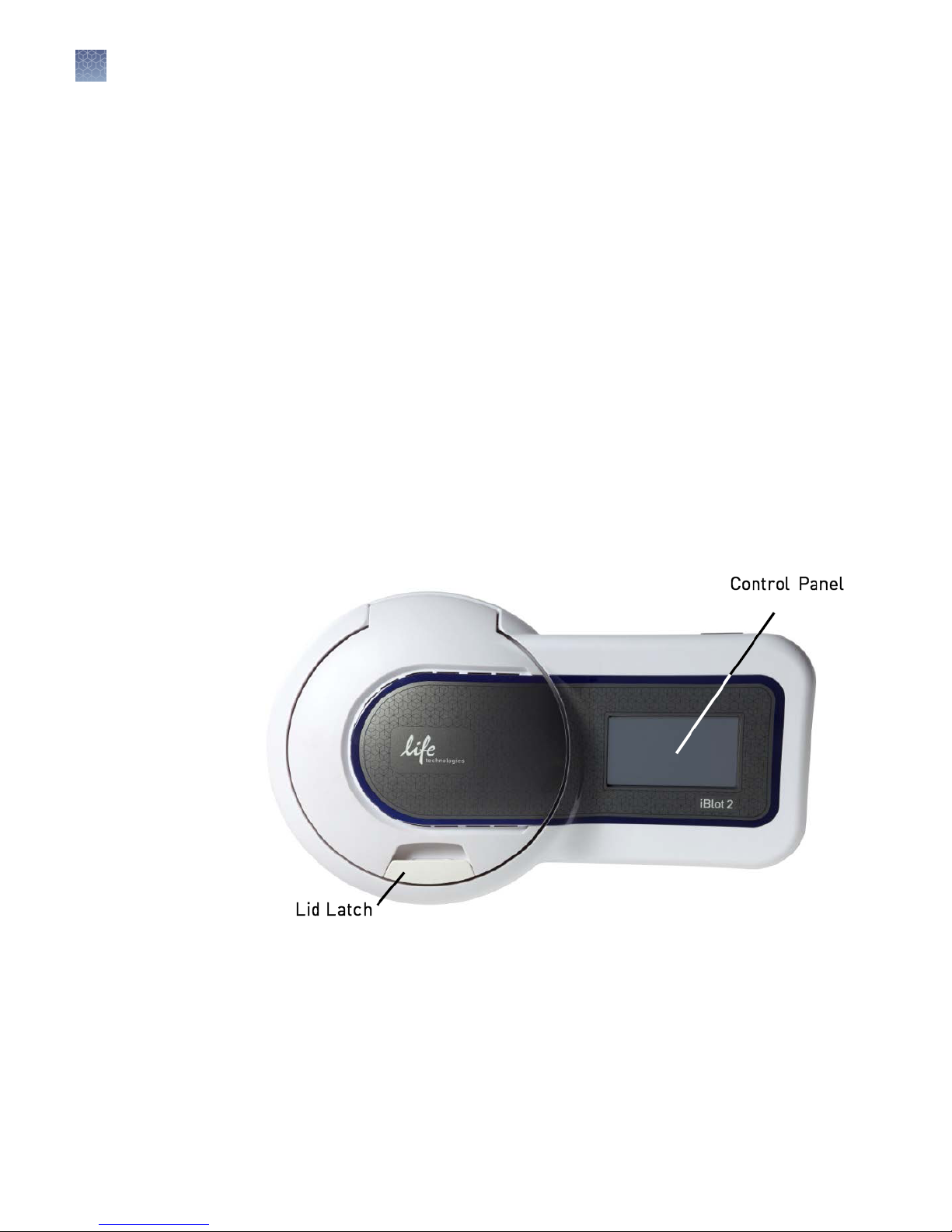
iBlot™ 2 Gel Transfer Device
Front view
The front-top view showing various parts of the iBlot™ 2 Gel Transfer Device is shown
below.
8
iBlot™ 2 Dry Blotting System User Guide
Chapter 1 Product information
About the system
1
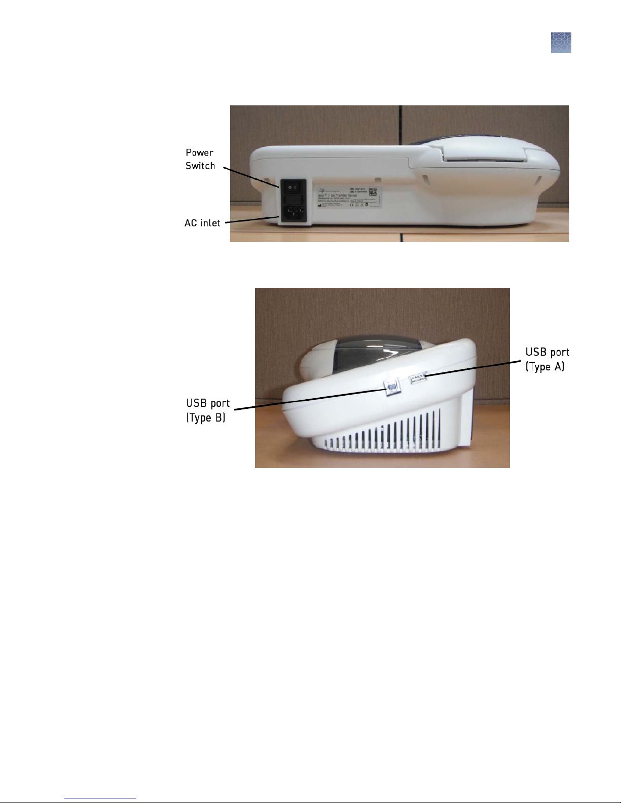
Rear view
Side view
A rear view showing various parts of the iBlot™ 2 Gel Transfer Device is shown below.
A side view showing various parts of the iBlot™ 2 Gel Transfer Device is shown below.
About the system
iBlot™ 2 Dry
Blotting System
iBlot™ 2 Dry Blotting System User Guide
The iBlot™ 2 Dry Bloing System consists of the iBlot™ 2 Gel Transfer Device and
associated iBlot™ 2 Transfer Stacks (sold separately). The iBlot™ 2 Gel Transfer Device
has a unique design, which, in conjunction with the patented gel matrix technology of
the iBlot™ 2 Transfer Stacks, results in a shortened distance between electrodes, high
eld strength, and high currents to reduce transfer times when bloing proteins onto
membranes.
Western bloing of proteins from midi- or mini-sized polyacrylamide gels onto
nitrocellulose or PVDF membranes within 7 minutes can be performed with iBlot™ 2
Transfer Stacks.
See the next page to understand how the iBlot™ 2 Dry Bloing System works and
“Description of parts“ on page 12 for details on various parts of the system.
9

Chapter 1 Product information
1
About the system
Features
System
components
• Pre-programmed (iBlot™ 2 Gel Transfer Device) with six Methods for transfer of
proteins from various gel types in 7–8 minutes
• Built-in safety features in the device enhance user safety
• User-friendly iBlot™ 2 Gel Transfer Device design with an integrated power
supply to avoid inconsistencies associated with the use of an external power
supply
• Fast, reliable protein transfer using iBlot™ 2 Transfer Stacks with integrated
nitrocellulose or PVDF transfer membranes for bloing without the need to
prepare buers
• Compatible for use with Bolt™ Bis-Tris PLUS™, NuPAGE™ Bis-Tris and TrisAcetate, Tris-Glycine, Tricine (in mini- and midi gel formats), and E-PAGE™ gels
iBlot™ 2 Gel Transfer Device
The iBlot™ 2 Gel Transfer Device is a self-contained bloing unit with integrated
power supply used for fast, dry bloing of proteins. See “iBlot™ 2 Gel Transfer
Device“ on page 12 for details.
iBlot™ 2 Transfer Stacks
The iBlot™ 2 Transfer Stacks are disposable stacks that have integrated PVDF or
nitrocellulose transfer membranes to perform dry bloing of proteins. Each iBlot™ 2
Transfer Stack contains a copper electrode and appropriate cathode and anode buers
in the gel matrix to allow fast, reliable transfer of proteins. See “iBlot™ 2 Transfer
Stacks“ on page 15 for details.
System overview
The iBlot™ 2 Dry Bloing System is based on the dry bloing concept, utilizing the
unique, patented gel matrix technology developed for E-Gel™ and E-PAGE™ gels for
the iBlot™ 2 Transfer Stacks.
The iBlot™ 2 Transfer Stack consists of a Boom Stack and a Top Stack sandwiching a
pre-run gel and a nitrocellulose (0.2 µm) or PVDF (0.2 µm) membrane. The iBlot™ 2
Transfer Stack is assembled with the bloing membrane on the anode side, and a prerun gel on the cathode side.
10
iBlot™ 2 Dry Blotting System User Guide

Chapter 1 Product information
About the system
Schematic of iBlot™ 2 Transfer Stack showing the flow of current
1
After the stack is assembled on the iBlot™ 2 Gel Transfer Device, and the appropriate
Method is selected, the run is initiated. Complete transfer of proteins from the gel to
the bloing membrane is accomplished in approximately 7–8 minutes. The rapid
transfer without the need for external power supply or premade buers is possible
due to the following features of the iBlot™ 2 Dry Bloing System:
• The gel matrix of the Boom and Top Stack incorporate the appropriate anode
and cathode buers to act as ion reservoirs. This format eliminates the need for
premade buers or soaked lter paper, and minimizes handling that can lead to
inconsistent performance.
• The copper anode does not generate oxygen gas as a result of water electrolysis,
resulting in increased transfer consistency. Conventional inert electrodes present
in other bloing systems result in oxygen generation, which can result in bloing
distortion.
• The design of the iBlot™ 2 Gel Transfer Device reduces the distance between the
electrodes and the integrated power supply. This unique design combined with
the gel matrix technology of iBlot™ 2 Transfer Stacks allows the system to
generate high eld strength and increase the transfer speed.
iBlot™ 2 Dry Blotting System User Guide
11
Chapter 1 Product information
1
Description of parts
Description of parts
iBlot™ 2 Gel
Transfer Device
The iBlot™ 2 Gel Transfer Device is a protein transfer device with an integrated power
supply capable of producing currents up to 6.3 amp, and supplying voltage up to
25 V. Four printed circuit boards hold the electronic components required to process
the systems logic unit, modify voltage and currents for display, and power the
bloing process. A pre-installed rmware controls the parameters such as voltage and
time, and allows selection of Methods (see “Description of methods“ on page 23 for
details on each Method).
IMPORTANT! When installing the iBlot
on a level surface. Keep the area around the device clear to ensure proper ventilation
of the unit. For your safety: Position the device properly such that the Power switch
and the AC inlet located at the rear of the unit (“Rear view“ on page 9) are easily
accessible.
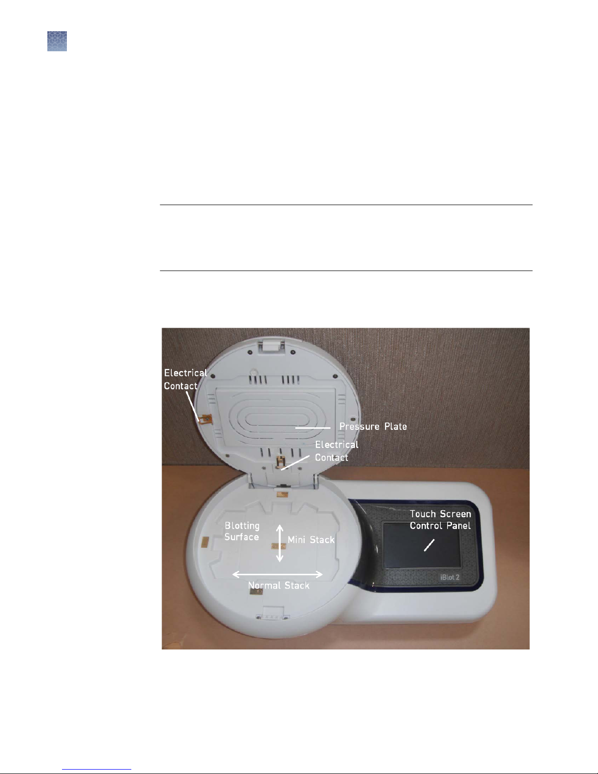
A top view of an open iBlot™ 2 Gel Transfer Device identifying various parts is shown
below. See “iBlot™ 2 Gel Transfer Device“ on page 8 for side and rear views of the
device.
™
2 Gel Transfer Device, make sure it is placed
12
iBlot™ 2 Dry Blotting System User Guide
Chapter 1 Product information
Description of parts
1
Blotting surface
The bloing surface is the area where the iBlot™ 2 Transfer Stacks containing the gel
are placed to perform bloing. Alignment guides are used for proper orientation of
normal and mini transfer stacks.
Lid
The lid of the iBlot™ 2 Gel Transfer Device contains ventilation holes to allow for
proper ventilation of the unit during the run. The pressure plate exerts even pressure
on the stack surface when the lid is closed.
Control panel
The Touch Screen Control Panel is a LCD display allowing the user to select Methods
and control the device. See “Control panel of the iBlot™ 2 Gel Transfer Device“ on
page 18 for control panel details.
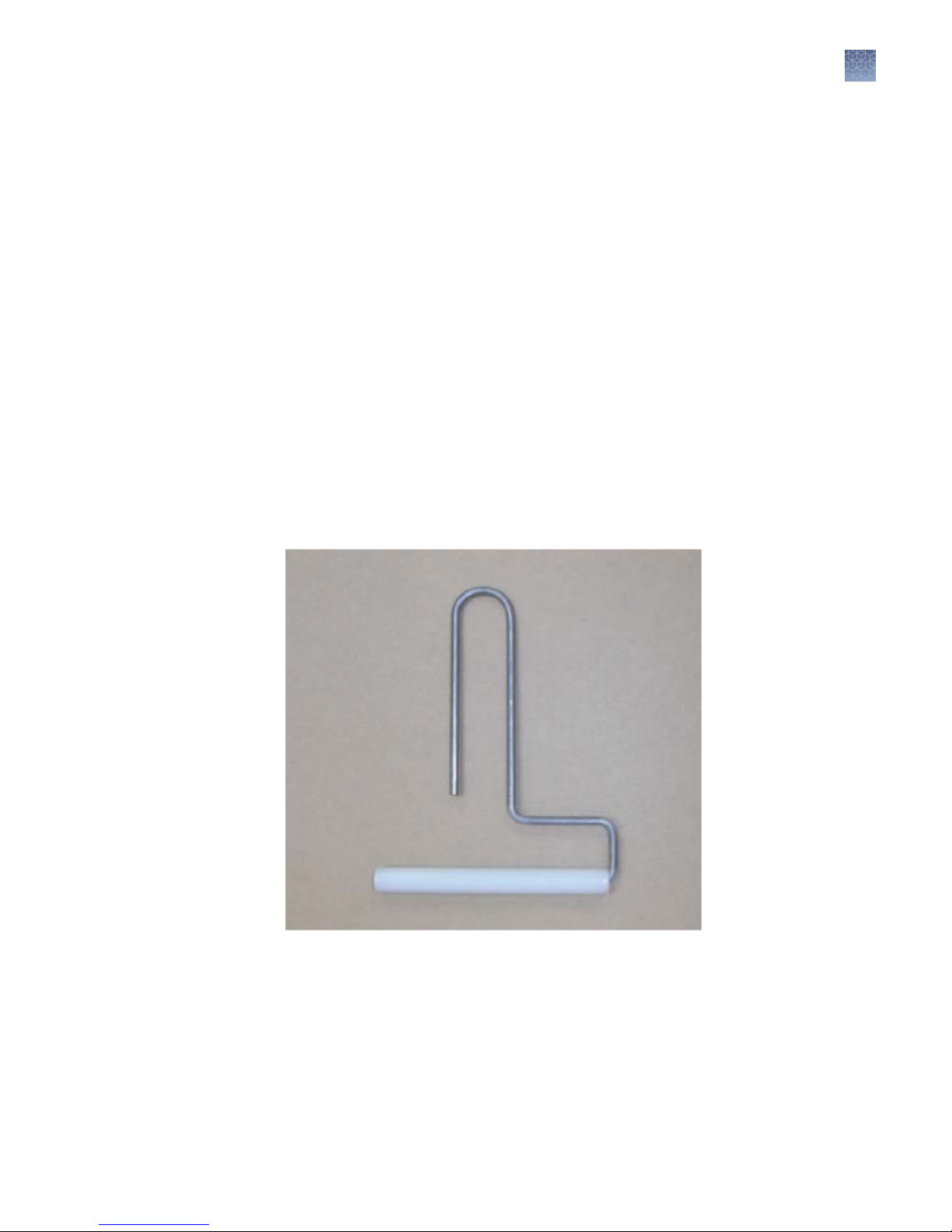
Blotting roller
The Bloing Roller is a plastic roller aached to a stainless steel handle (8.6 cm wide).
The Bloing Roller is used to remove any air bubbles between the gel and bloing
membrane during the assembly of the stacks and gel.
iBlot™ 2 Dry Blotting System User Guide
13
Chapter 1 Product information
1
Description of parts
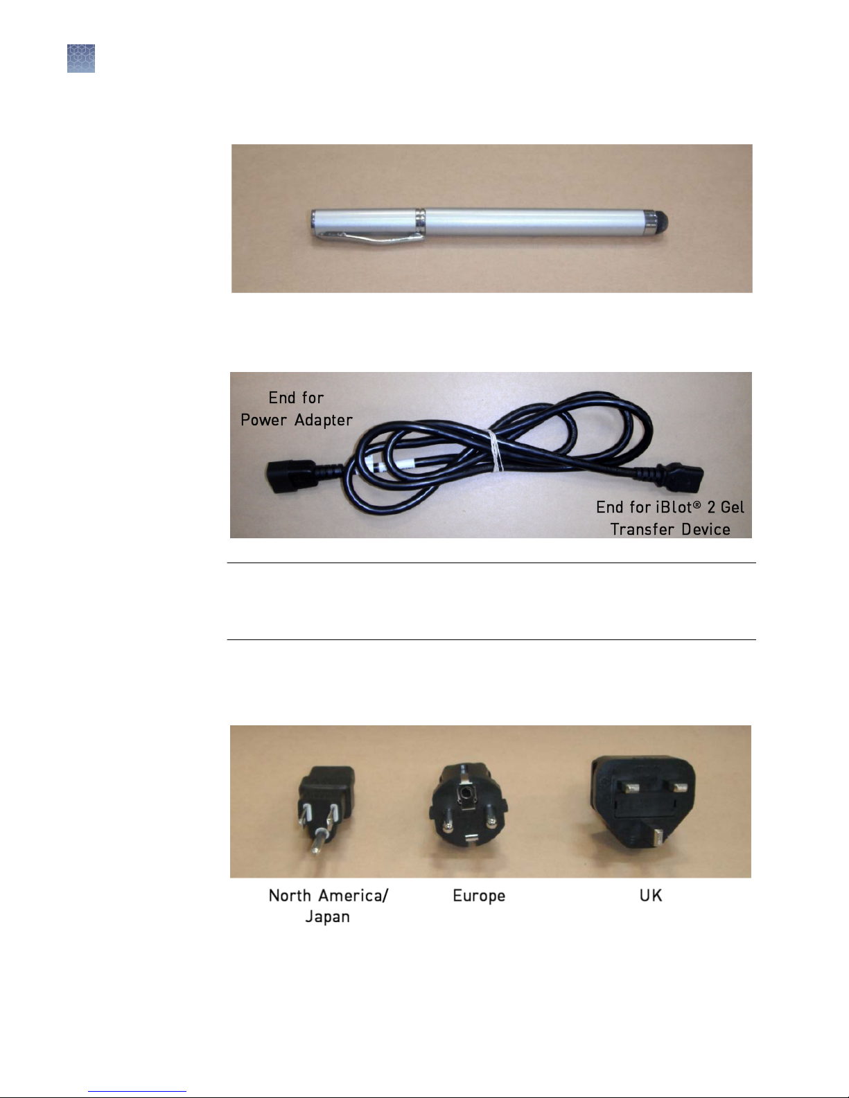
Stylus
Power cord
A stylus is provided for use with the touch screen of the iBlot™ 2 Gel Transfer Device.
The Power Cord connects to the iBlot™ 2 Gel Transfer Device on one end, and to a
power adapter (for plugging into an AC electrical outlet) on the other.
Power adapters
IMPORTANT! Be sure that the AC power switch is in the O position (“Rear
view“ on page 9) before aaching the power cord. Aach the power cord to the AC
inlet of the device rst, and then to the electrical outlet. Use only properly grounded
AC outlets and power cords.
Power Adapters (North America/Japan, Europe, UK) are used to connect the power
cord to an AC electrical outlet. Use the appropriate adapter for your geographical
region.
14
iBlot™ 2 Dry Blotting System User Guide

Chapter 1 Product information
Description of parts
1
iBlot™ 2 Transfer
Stacks
Guidelines for
iBlot™ 2 Transfer
Stacks
The iBlot™ 2 Transfer Stacks are used to transfer proteins from gels onto nitrocellulose
or PVDF membranes, and are available in Standard size for bloing E-PAGE™, midi-,
or two mini gels, and Mini size for bloing one mini gel.
See “iBlot™ 2 Transfer Stack specications“ on page 55 for iBlot™ 2 Transfer Stack
specications.
• Store the iBlot™ 2 Transfer Stacks at room temperature. For best results, use the
transfer stack before the expiration date printed on the package for each stack.
• Do not remove transfer stacks from boom plastic tray. The plastic tray is a
central part of the consumable. It maintains the current within the stacks and
separates it from the rest of the device. The plastic tray also contains any liquid to
allow easy clean-up.
• Discard the iBlot™ 2 Transfer Stack after every use. Do not reuse the iBlot™ 2
Transfer Stack.
• Do not use iBlot™ Transfer Stacks in the iBlot™ 2 Gel Transfer Device, or mix
components between iBlot™ Transfer Stacks and iBlot™ 2 Transfer Stacks. Use
iBlot™ 2 Transfer Stacks only for their designated application.
Note: The maximum voltage and current of the output to the gel stacks is 25 VDC
and 6.3 Amp.
The following iBlot™ 2 Transfer Stacks are available at thermosher.com/iblot2 (see
“iBlot™ 2 Transfer Stacks“ on page 57 for ordering information).
Product
iBlot™ 2 Regular Transfer
Stacks
iBlot™ 2 Mini Transfer
Stacks
Regular or Mini iBlot™ 2 Transfer Stacks come with the following components:
Component
iBlot™ 2 Transfer Stack 10 10
iBlot™ 2 Absorbent Pad,
Regular
iBlot™ 2 Absorbent Pad, Mini 10 —
iBlot™ Filter Paper, Regular — 10
iBlot™ Filter Paper, Mini 10 —
Transfer Membrane Cat. No.
Nitrocellulose
PVDF
Nitrocellulose
PVDF
Mini Regular
— 10
IB23001
IB24001
IB23002
IB24002
iBlot™ 2 Dry Blotting System User Guide
15
Chapter 1 Product information
1
Description of parts
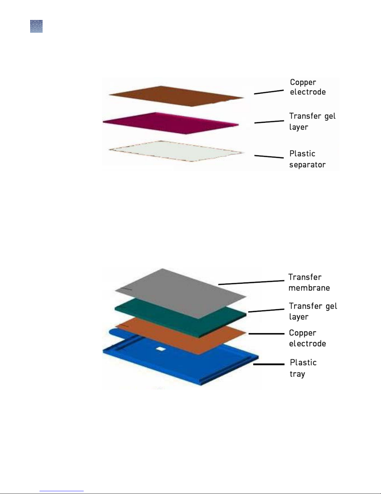
Top stack
Bottom stack
The Top Stack is separated from the Boom Stack by a white plastic separator, and
contains a copper electrode and a transfer gel layer. The transfer gel layer acts as an
ion reservoir and is composed of an optimized, proprietary gel composition.
The Boom Stack contains a copper electrode, transfer gel layer, and a nitrocellulose
(0.2 µm) or PVDF (0.2 µm) membrane for protein transfer. The transfer gel layer acts
as an ion reservoir and is composed of an optimized, proprietary gel composition. The
transparent plastic tray in which the iBlot™ 2 Transfer Stack is packaged serves as the
support for assembling the transfer stacks with the gel.
The nitrocellulose (0.2 µm), and PVDF (0.2 µm) membranes do not require any
pretreatment before use and minimize protein blow-through during the iBlot™ 2
bloing process.
Transfer
membrane
Always use the Boom Stack with the tray in the iBlot™ 2 Gel Transfer Device.
The iBlot™ 2 Transfer Stacks are assembled with the transfer membrane and are
available with:
• Nitrocellulose membrane (0.2 µm)
The nitrocellulose membrane is composed of 100% pure nitrocellulose to provide
high-quality transfer. The membrane is compatible with commonly used
detection methods such as staining, immunodetection, uorescence, or
16
iBlot™ 2 Dry Blotting System User Guide
Chapter 1 Product information
Description of parts
radiolabeling. The proteins bind to the membrane due to hydrophobic and
electrostatic interactions. The protein binding capacity is 209 µg/cm2.
• PVDF membrane (0.2 µm, low uorescence)
The PVDF membrane has higher binding capacity than nitrocellulose. The PVDF
membrane is preactivated and ready for use without any pretreatment with
alcohol. The membrane is compatible with commonly used detection methods
such as staining, immunodetection, uorescence, or radiolabeling. The proteins
bind to the membrane due to hydrophobic interactions. The protein binding
capacity is 240 µg/cm2.
1
™
iBlot
Filter Paper
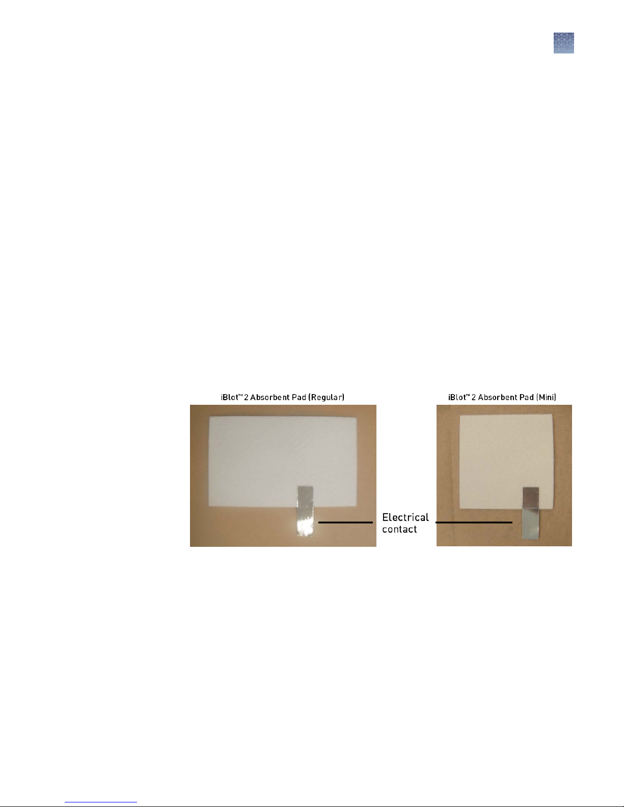
iBlot™ 2 absorbent
pad
The iBlot™ Filter Paper is used for bloing mini- or midi gels. The iBlot™ Filter Paper is
placed on top of the pre-run gel before placing the Top Stack to protect the gel
integrity during the bloing process. The iBlot™ Filter Paper is supplied in two sizes
(see “iBlot™ 2 Transfer Stack specications“ on page 55 for dimensions) for ecient
bloing of mini- and midi gels. Do not use the iBlot™ Filter Paper for bloing
E-PAGE™ gels.
Note: Failure to use the iBlot™ Filter Paper during bloing of mini- or midi gels may
result in high currents exceeding the current limit leading to a “High Current Error”
during the run.
The iBlot™ 2 Absorbent Pad absorbs any excess liquid on the stacks formed during
bloing and generates even pressure on the stack assembly. It is placed on top of the
assembled iBlot™ 2 stack prior to transfer.
When properly assembled, the electrical contact of the iBlot™ 2 Absorbent Pad is
aligned with the corresponding electrical contacts on the bloing surface of the iBlot
2 Gel Transfer Device to allow completion of the electrical circuit. See “iBlot™ 2
Transfer Stack specications“ on page 55 for dimensions of the iBlot™ 2 Absorbent
Pad.
Discard the iBlot™ 2 Absorbent Pad after every use. Do not reuse the iBlot™ 2
Absorbent Pad.
iBlot™ 2 Dry Blotting System User Guide
™
17

Chapter 1 Product information
1
Operating the iBlot™ 2 Gel Transfer Device
Operating the iBlot™ 2 Gel Transfer Device
First time usage
of the iBlot™ 2 Gel
Transfer Device
The rst time the iBlot™ 2 Gel Transfer Device is turned on, you will need to perform
the following actions:
Congure the clock by touching the appropriate elds and entering the values.
1.
Touch Enter when done. Then Touch Done on the Date & Time screen.
The Tutorial screen is displayed. Take the tutorial if desired (the tutorial guides
2.
the user to assemble a stack and allows you to run the P0 Method if a stack is in
the device. Otherwise hit Cancel to go to the Home Screen).
OR skip the tutorial to go to the Home Screen.
3.
Control panel of
the iBlot™ 2 Gel
Transfer Device
18
The control panel is a touch screen display allowing:
Running the Method that was last used on the device
1.
Note: This icon will not appear until after the rst time the function is used.
Running Preset Templates (Default Methods)
2.
Programming Custom Methods
3.
Note: For details on creating Methods, refer to “Creating custom methods“ on
page 36.
Running Custom Methods
4.
Note: This icon will not appear until after the rst time the function is used.
iBlot™ 2 Dry Blotting System User Guide
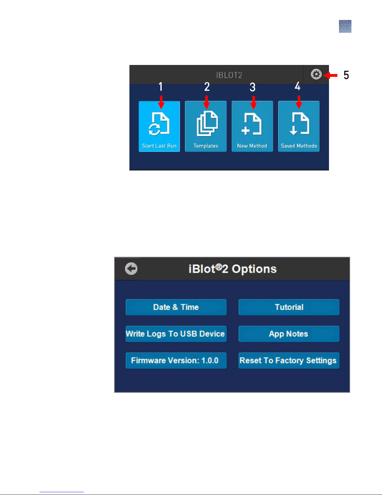
Accessing the Options screen
5.
Chapter 1 Product information
Operating the iBlot™ 2 Gel Transfer Device
1
iBlot™ 2 Gel
Transfer Device
options screen
The Options screen allows the user to perform the following actions:
• Set date and time
• View a step-by-step tutorial for the iBlot™ 2 Gel Transfer Device
• Write logs to a USB device
• View application notes
• Upgrade rmware
• Reset the iBlot™ 2 Gel Transfer Device to factory seings
iBlot™ 2 Dry Blotting System User Guide
19
Chapter 1 Product information
1
Operating the iBlot™ 2 Gel Transfer Device
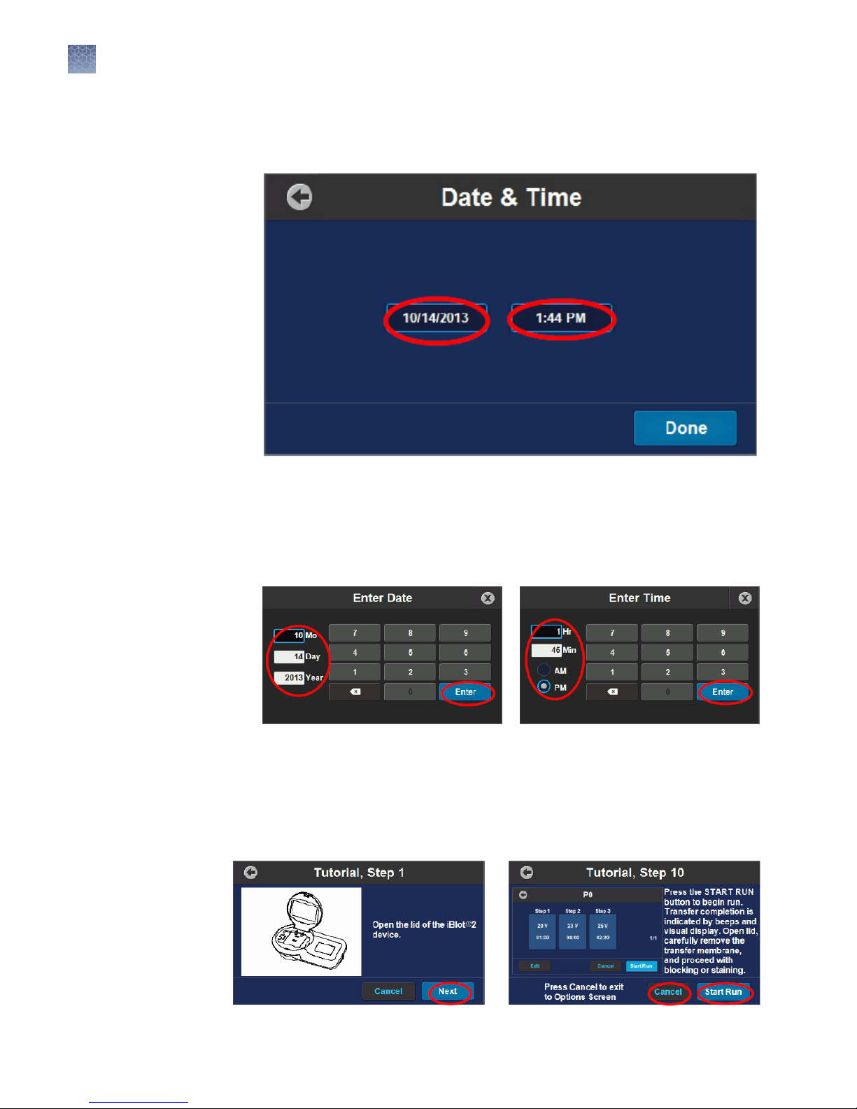
Setting date and
time
Touch Date & Time to access the Date & Time screen.
Touch the Date or Time eld to access a keyboard for entering values.
1.
Touch the elds that you want to change, and enter the appropriate value with
2.
the keyboard. Touch Enter when done.
iBlot™ 2 Gel
Transfer Device
tutorial
After entering the Date and Time, touch Done on the Date & Time screen to
3.
return to the Options screen.
The Tutorial buon provides step-by-step instructions for assembling and running a
transfer stack on the iBlot™ 2 Gel Transfer Device.
If following the tutorial to assemble a stack in real time, you can perform a run using
the default P0 Method at step 10. Touch Cancel to return to the Options screen if you
do not wish to perform a run.
20
iBlot™ 2 Dry Blotting System User Guide

Chapter 1 Product information
Operating the iBlot™ 2 Gel Transfer Device
1
Writing logs to a
USB storage
device
A record of each run is kept by the iBlot™ 2 Gel Transfer Device, with voltage and
current being tracked at 1-second intervals. This information can be downloaded to a
USB storage device in “.csv” format.
Insert a USB storage device into the USB port (Type A) of the iBlot™ 2 Gel
1.
Transfer Device.
Touch Write Logs to USB Device on the Options screen.
2.
Note: If you do not have a USB storage device in place, a prompt to insert a USB
storage device will appear. Touch OK to start the transfer after inserting the USB
storage device.
Do not remove the USB storage device until the Options screen is displayed
3.
again.
iBlot™ 2 Gel
Transfer Device
application notes
The les are saved to folders titled “iBlot™2_Logs” and “iBlot™2_ErrorLogs” on
4.
the USB storage device.
The App Notes buon provides access to application notes for improving transfer
under various conditions when using the iBlot™ 2 Gel Transfer Device.
iBlot™ 2 Dry Blotting System User Guide
21
 Loading...