

Page 1

IFA12 Pet Keeper®Indoor Transmitter
Operation, Installation & Training Manual
Made in the USA
Page 2

Thank you for choosing an Invisible Fence®Pet Containment System
We believe that you now own the highest quality electronic pet containment system made anywhere. We support this claim by backing Invisible
Fence Brand products with a One-Year, Money-Back
Performance Guarantee*, and Warranties which
include lightning and surge damage. Refer to your
warranty card or the back of your sales contract for
complete details. All of this is backed up by our inter-
national network of local Invisible Fence professionals who offer you professional installation, Safe Dog
pet training, and prompt service.
You are the most important judge of our pro ducts and services. When you tell us that we have met
or exceeded your expectations for Inv i s i ble Fe n c e
p ro d u c t s , then we are ach i eving our go a l : to continuo u s ly ke ep your pet safe at home™.
* Good only on pro fe s s i o n a l ly installed systems.
®
1
Page 3

Important Safeguards
1. Read and Retain Manuals: Read all of the
operating and training instructions before installing
and/or using your new Invisible Fence®Brand pet containment system.
2. Training: Train your pet according to the
i n s t ructions in Inv i s i ble Fence training manu a l s .
Complete all of the steps before allowing your pet to
run free.
3. Obey all Cautions and Warnings: Adhere to
all of the cautions and warnings contained in this manual and all other manuals pertaining to your Invisible
Fence system, and on all Invisible Fence components.
4. Service and Repair: Do not attempt to service
an IFA 12 transmitter yourself. Refer all service to an
authorized Invisible Fence professional only.
5. For Animal Use Only:All Invisible Fence pet
containment systems are designed for animal use only.
Never attempt to use this product for any purpose not
specifically described in this manual.
IMPORTANT: If, for any reason, your Invisible
Fence system does not operate as described in this
manual, or if you encounter any difficulty training
your pet, call your Invisible Fence professional immediately.
Warning: The following precautions
should always be taken.
1. Never attempt to install an Invisible Fence pet
containment system unless you have first consulted
your Invisible Fence professional and have Invisible
Fence installation instructions.
2. Never install an IFA 12 outdoors or where it
could be exposed to the outdoor elements, doing so
will void the manufacturer’s warranties.
3. Check the transmitter periodically to make
sure that it is operating properly and is producing a
signal field.
4. Caution: Always take the Computer Collar
off your pet before making any adjustment to any
Invisible Fence equipment.
5. If you have any questions about any aspect of
your Invisible Fence system,please call your Invisible
Fence professional immediately.
Warning: If you have any reason to
believe that your pet may pose a
danger to others, or that it may harm itself
if it is not kept from crossing the Invisible
Boundary®signal field, you should not rely
solely on this product to contain your pet.
Invisible Fencepet containment
will not work unless:
1. The 12vAC transformer is plugged into the
transmitter and is plugged into a 110vAC outlet.
2. The transmitter is turned on and is producing a
signal field.
3. The Computer Collar is correctly fitted and
worn by your pet.
The Computer Collar is adjusted so that the
receiver posts are touching your pet’s skin.
4. The Power Cap®battery in the receiver is good
and is correctly installed.
5.You train your pet as prescribed in the Invisible
Fence training protocol.
Do Not become overly confident that your pet
has become conditioned to the Invisible Fence system
sooner than expected. Complete all of the training
steps before allowing your pet to run free.
If you have any questions about any aspect of
your Invisible Fence system, please call your Invisible
Fence professional immediately.
· At Least Once a Month, and After a Thunder
Storm, Check the Width of Your Invisible Fence
System’s Signal Field
Always keep a note of the width of your
system’s signal field.
Always check the signal field from the same
place.
Take the Computer Collar off your pet. Follow
the instructions for checking the width of the signal
field on page 5.
If the receiver does not sound a warning
®
where the edge of the signal is supposed to be,
or if it only sounds a warning when it is closer to
the transmitter than the setting of the signal field,
immediately call your Invisible Fence professional
for service.
Use other means to contain your pet until all
necessary service has been completed.
2
Page 4

IFA 12 Installation
Features and Functions
The IFA 12 is designed for indoor use only.
The IFA 12 transmitter is microprocessor controlled and designed to work with an Invisible Fence
Computer Collar®to contain your pet within ta certain
area, or to block your pet’s access to an area.
Unlike other Invisible Fence indoor and outdoor
systems, an external signal field wire is not connected
to the transmitter. The Invisible Boundary®wire is
contained within the transmitter’s case.
The IFA 12 has a green LED that stays on without blinking to indicate that the transmitter has power
and is turned on.
The tra n s m i t t e r ’s case is fa c t o ry sealed and cannot
be opened. Its power jack and signal field setting contro l s
a re located in a gro ove on the outside of the case.
Left to right: 12vAC power jack, signal field
adjustment knob, 7KHz-10KHz channel switch.
The IFA 12 has a switch to select the transmitter’s operating frequency,7K is the the LEFT position,
10K is the RIGHT position.
There is one signal field adjustment knob that is
used to set the width of the signal field.
The Signal Fi e l d
All Inv i s i ble Fence Brand tra n s m i t t e rs produce a
coded, low power radio signal. This signal is what activates your pet’s Computer Collar receiver.
The IFA 12 signal fi e l d is omnidirectional. It’s a
s p h e re surrounding the tra n s m i t t e r, t h at is centered on the
t ra n s m i t t e r, and is broadcasted out 3 6 0 ˚in all dire c t i o n s
f rom the unit.
Planning the Installation
Warning: IFA12 transmitters are
designed for indoor use exclusively.
If an IFA 12 is used outdoors, it will be cause
to void the manufacturer's warranty in full.
You must locate an IFA 12 within 6 feet of a
110v outlet because of the length off the transformer’s
®
power cord. Unless you absolutely must,
never use an outlet that can be turned ON and
OFF by a wall switch. If you have to use an outlet that
is not dedicated ON, there is a risk that the IFA 12 may
be inadvertently turned OFF without you realizing it.
Never permanently fasten an IFA 12 in place
until after you have set and checked the width of the
signal field and are sure of the area that the signal field
will cover. It may be necessary to move the transmitter
to have the signal field cover the area you want it to.
The signal generated by an IFA 12 can be picked
up by other conductors like television cable, copper
plumbing lines, metal window and door frames, and
metal furniture and furniture frames. If your objective
is to keep a pet away from a table, couch, or bed by
putting an IFA 12 under the piece of furniture and the
signal bleeds to that piece of furniture, it may not be a
problem. However, if you use an IFA 12 to protect an
area and the signal bleeds to a metal object that is
nearby, but not supposed to be within the protected
area, you may have to change the location of the transmitter..
To prevent the signal from bleeding, the transmitter should be located a few feet away from conductors
like TV cable, copper pipes, and metal ducts. When an
object like metal furniture, or furniture with an internal
metal frame, or a metal door frame is nearby, an IFA
12 should be located so that the edge of the signal field
will be a few feet away from it. When you are setting
and checking the width of the IFA 12 signal field, use
a Computer Collar and check all of the possible conductors within 10 feet(3.1m) of the transmitter to see if
any of them are picking up the signal.
An IFA 12 can be mounted on a wall or laid flat
on the floor and placed beneath an object, such as a
sofa or chair.
3
Page 5
IFA 12 Installation continued
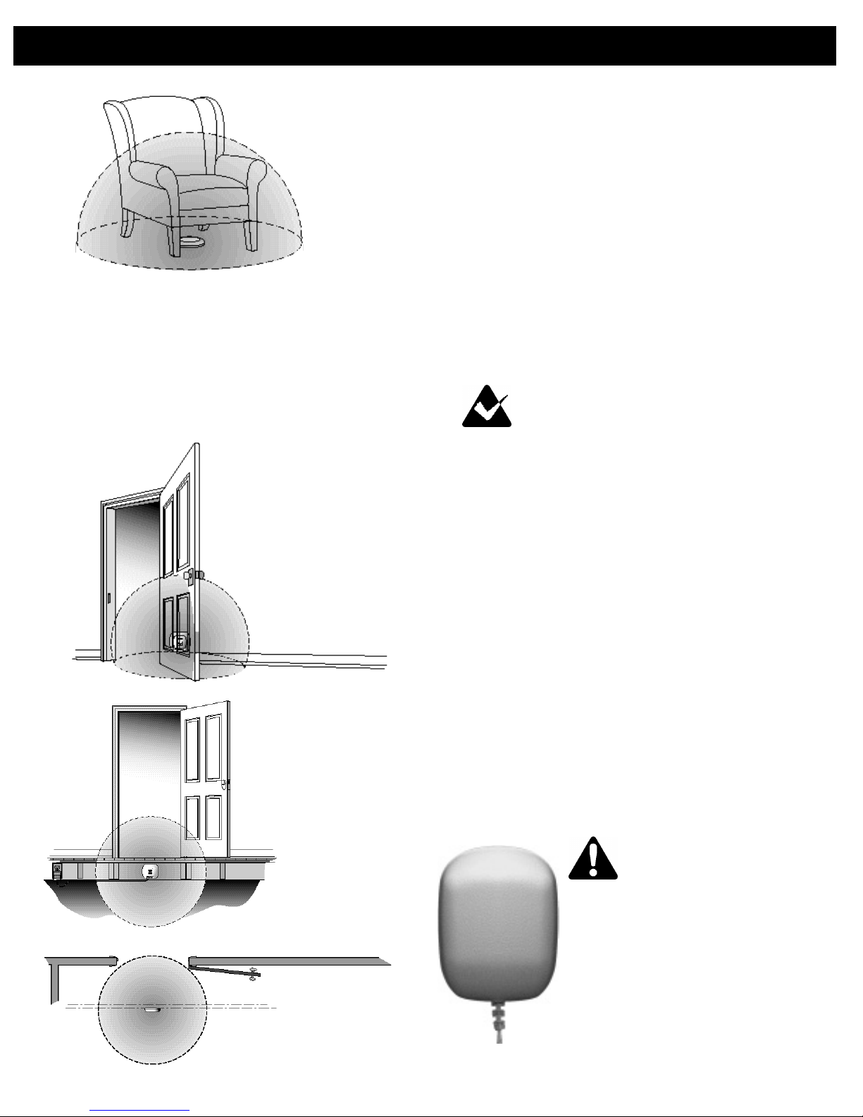
An IFA 12 used to
keep a pet off
a chair.
Whenever you have a choice, do not locate an
IFA 12 transmitter out in the open in a living area.
Look around an area that you want to protect and consider the various places where you can locate the
transmitter to have the signal field protect the area that
you want it to. Can it be hidden under a piece of furniture, behind a bookcase or a sideboard, or in a built-in
cabinet? Can it be located in the basement under the
area that it will protect?
To block a stairwell see if you will be able to fasten the IFA 12 under the stairs in the basement, or on
the bottom of a step or the back of a riser. If there is an
electric outlet in a closet that is under a staircase, a
wall inside the closet may be a good place to put an
IFA 12 to block the stairs. Locate the transmitter so
that it blocks the end of the staircase that would otherwise be the entrance to the stairs. Block the access so
that your pet will stop on the floor in front of the stairs
and won’t have to turn around on the stairs. For example, if your pet is to be kept from going upstairs block
the bottom of the staircase. To keep your pet from
going downstairs block the top of the staircase.
Note: Never install an IFA 12 on the
ceiling in a room or above a stairwell in
the living area of your home.
Mounted on the wall
behind the door, close to
the entrance to the room
that it is supposed to
block, this IFA 12 is
also blocking the hall
outside of the room.
Located in
the basement
under the room,
this IFA 12 is
only blocking
the entrance
to the room.
IFA 12, 12vAC Transformer, Model 100-0020-01
Turn on the IFA 12 by plugging the 12vAC transformer’s power line into the power jack on the transmitter marked PWR, then plug the transformer into a
110vAC outlet. The green LED on the face of the
transmitter will light indicating that the power is connected and the transmitter is on.
Any customer with another electric power source
should ask their Invisible Fence®professional for an
appropriate adapter.
Only use the model 100-0020-0l, 12vAC transformer provided with the IFA 12. This transformer
will supply the output necessary to power the IFA 12.
Specifications:
INPUT: 120vAC 60 Hz 15W
OUTPUT: 12vAC 750mA
UL/CSA CLASS 2 Transformer
UL listed/CSA certified
Warning: The model
100-0020-01 is the
only transformer authorized
by Invisible Technologies, Inc.
to be used to supply the power
to an IFA 12. The use of any
other transformer may result
in a malfunction of the
IFA 12 transmitter.
4
Page 6

IFA 12 Installation continued
Emergency battery backup power is not available
for the IFA 12.
Setting and Checking the Width of the Signal Field
C a u t i o n : N ever install any Inv i s i bl e
Fe n c e®B rand equipment or make any
adjustment to the signal field while your pet
is we a ring its Computer Collar®.
If your pet is we a ring the Computer Collar,
be sure to re m ove it befo re you do any wo rk .
Before you set the width of the signal field, check
to make sure that the 7K-10K channel switch on the
IFA 12 is set to the same operating frequency as the
Computer Collar receiver that your pet will be wearing, and the same operating frequency as any other
transmitter(s) that may be part of your indoor system.
Because the signal field from an IFA 12 is omnidirectional, the width of the signal is a radius. It is
measured from the point where a Computer Collar
receiver sounds a warning to the center of the transmitter.
The width of the signal field can be set from a
minimum of 1 foot(.3m) to a maximum of 7 feet
(2.1m). The IFA 12 signal field is typically set 2 to 3
feet(.6 to .9m) wide for most applications.
Turning the signal field adjustment knob clockwise decreases the width of the signal field, and turning it counter clockwise makes the signal field wider.
These adjustments do not change the correction
level of the receiver, they only change the width of the
signal field from the IFA 12 transmitter
To keep a pet out of a specific room, for example:
1. Use a 110vAC outlet that is close to the doorway of the room that your pet is to be excluded from.
Plug the transformer into the IFA 12 power jack, then
plug the transformer into the 110v outlet.
2. Set the operating frequency so it is the same as
your pet’s Computer Collar receiver, 7k or 10k.
3. Turn the signal field adjustment knob fully
clockwise to the lowest setting. Then turn it up about
“ten minutes”, counter clockwise.
4. Put the IFA 12 near the hinged side of the door
frame and check the width of the signal field with the
receiver. If the receiver activates across the entire
doorway this setting is sufficient to block the entrance
If this signal field setting is not wide enough to
cover the area that you want it to, turn the signal field
adjustment knob counter clockwise another “ten minutes” and check the width of the signal field again.
Repeat this process, making gradual changes, until the
signal field is wide enough to cover the area.
5. Next, use the receiver to check that this placement does not block your pet's access to other areas,
such as a hallway or exterior doorway where you want
your pet to be able to pass.
6. If the proper area is being blocked, the IFA 12
may be permanently fastened where it is.
7. If not, reposition the IFA 12 farther away from
the pass area while maintaining signal coverage of the
doorway you want to block. This may require any of
the following:
A. Moving the IFA 12 to the latch side of the
door frame if it is farther away from the pass area.
B. Moving the IFA 12 away from the door and
resetting the signal field. A larger field may provide
better coverage of the doorway.
C h e ck the width of the signal
field by holding a Computer Collar so
that the receiver is at about the same
height and on the same angle that it will be
when your pet is wearing it. Start farther
away from the transmitter than you think
that the width of the signal field will be
and walk slowly toward the IFA 12.
The receiver will sound a warning when it is at the edge
of the signal field.
Note: A Computer Collar receiver
has a fail safe mechanism.
The receiver will go through three complete
cycles of 10 seconds on and 10 seconds off
and then shut down. It will not reactivate
until it is taken completely out of the the
signal field, and is then brought back into it
Remember, the distance from the point where the
Computer Collar receiver sounds a warning to the center of the transmitter is the width of the signal field.
Because the IFA 12 signal field is a sphere it
is very important to check the width of the signal field
at different locations all around the transmitter. You
want to be sure that the signal field is wide enough to
cover the area that you want it to, but just as importantly, be sure that it is not so wide that it is also cover-
5
Page 7

IFA 12 Installation continued
ing an area that is not supposed to be covered.
When the signal field is covering the area that
you want it to, permanently fasten the IFA 12 in place.
Mark the signal field setting on the IFA 12.
Note: When the signal field is set where
you want it, you can use a tiny dot of
nail polish or paint on the signal field
adjustment knob and the case of the IFA 12
to mark the setting for future reference.
Mounting the IFA 12 Transmitter
To permanently fasten an IFA 12 in place, drill
two pilot holes aligned vertically and centered 2 1/2
inches(6.35cm) apart. Turn a 3/4 inch, #10
(4.8x19mm) pan-head sheet metal screw into each
pilot hole until about 1/16 of an inch(1.6mm) of space
remains between the surface the transmitter will be
located on and the underside of the screw’s head.
Center the round end of the keyholes on the bottom of
the transmitter’s case over the screws so that the bottom of the transmitter is flush against the mounting
surface. Slide the transmitter down to lock the heads of
the screws in the keyholes.
Computer Collar®Receivers
Warning: The A12 Computer Collar is
designed for indoor use exclusively,
using an A12 outdoors will void the
manufacturer’s warranty in full.
Note: An A12 Computer Collar receiver
will not work with any outdoor Invisible
Fence transmitter, or any indoor transmitter
except an IFA 12.
Note: The A12 Computer Collar
receiver is factory set to 7K, it will not
work with an IFA 12 when the transmitter’s
operating frequency is set to 10K.
Note: If you want to use both an indoor
IFA 12 system and an outdoor Invisible
Fence®system, you can use the same R series
Computer Collar for both systems. The IFA 12
transmitter(s) must be set to the same operating
frequency that the outdoor system’s transmitter
is set to, either 7K or 10K.
CAUTION AND CARE
An Inv i s i ble Fence Computer Collar
will not wo rk unless:
1. You train your pet as pre s c ribed in the
I nv i s i ble Fence Safe Dog®training protocol.
2 . The Computer Collar receiver is wo rn snu g ly on
your pet’s neck under the lower jaw.
3. The Computer Collar is adjusted so that the
receiver’s posts are touching your pet’s skin.
4. The Power Cap®b at t e ry in the C o m p u t e r
C o l l a r re c e iver is good and is corre c t ly installed, see
“Changing the Computer Collar Receiver’s Power
Cap Battery”, on page 7.
5. The IFA 12 is on and producing a signal
fi e l d.
The following precautions should also be taken:
1. A lways take the Computer Collar off
your pet befo re you make any adjustment
to your Inv i s i ble Fence system.
2. Gra d u a l ly allow your pet to become accus-
tomed to its new Computer Collar. Ta ke off the
collar eve ry night during the fi rst month and perio d i c a l ly there a f t e r. This will ensure proper fit and
avoid the possibility of any irritation that the posts
may cause to your pet’s skin.
3. Check the Computer Collar near your tele-
v ision set(s). Although the re c e iver has a decoding circ u i t , some televisions may produce a coded
signal similar to the Inv i s i ble Fence signal and
m ay cause the re c e iver to activate when it is cl o s e
to a telev i s i o n .
4. DO NOT s e c u re the corre c t i o n
posts in the re c e iver with any kind
of glue or adhesive.
A LWAY S use the post
tightening tool to tighten
the re c e iver posts.
6
Page 8

Computer Collar®Receivers continued
5. Check the tra n s m i t t e r p e ri o d i c a l ly to
m a ke sure that it is operating pro p e rly and pro d u cing a signal fi e l d.
6. NEVER, under any circ u m s t a n c e s , u s e
this pro d u c t for any purpose other than that
s t ated in this m a nual. Inv i s i ble Fe n c e systems are
designed for animal use only.
Features and Functions
Computer Collar receivers are water resistant,
microprocessor controlled units powered by a special
3v lithium Power Cap®battery.
An R series Computer Collar can be used with all
ICT700 series,Invisible Gate®, and IFA 12 transmitters.
Computer Collar receivers are available with
Short, Long, or Short-Space receiver posts to fit different size dogs and work well with any type of coat
Computer Collar receivers can be fitted w i t h
shunts to reduce the correction level of the
re c e iver fo r small pets who are shy or timid.
receiver.
The three small circular
indentations, equidistantly
spaced around the outer
edge of the base that supports the center battery contact in the receiver, indicate
that the receiver is an R21
v3 series Computer Collar.
Fitting the Computer Collar
To wo rk pro p e rly, the correction posts on the
Computer Collar receiver must touch your pet’s skin.
Posts are ava i l able in three diffe rent sizes to ensure
a proper fit for eve ry pet: s h o rt , 1/2 inch ( 1 2 . 7 m m ) ;
l o n g, 3/4 inch(19mm); and short-spaced posts.
The re c e iver should be positioned undern e at h
your pet’s neck with the posts pointing up and the
top of the re c e iver pointing fo r wa rd, t owa rd yo u r
p e t ’s nose. Adjust the collar so it’s snug enough to
slide one fi n ger between a post and your pet’s neck .
Pe riodic adjustment of the Computer Collar may be
n e c e s s a ry as your pet’s coat , weight and age
ch a n ge.
Short, Long, and
Short-Space Receiver Posts
R21 v3 Series Receivers
The R21 v3 Computer Collar receivers have an
added feature. The v3 will beep once when a Power
Cap®battery is installed. The beep indicates that the
microprocessor in the receiver is working and that the
Power Cap battery has enough voltage to power the
Make sure that the Computer Collar is snug
enough for the posts to touch your pet’s skin.
Be sure that you
can still work
a fingertip
between the skin
and the post.
Changing the Computer Collar Receiver’s
Power Cap Battery
The Power Cap battery is a
replaceable 3v lithium battery with a
unique plastic screw cap. It is very
important for proper operation that the
receiver always has a good Power Cap
®
7
Page 9

Computer Collar®Receivers continued
battery installed. On average, the battery should be
changed every 3 to 4 months. But battery life can be
reduced by several variables, including lower temperatures, the number of times a pet challenges the system
boundary, and the fit of the collar on the pet’s neck. In
cold weather, for example, it may be necessary to
replace the battery more often. Your Invisible Fence
professional should recommend a schedule for regularly changing a receiver’s Power Cap® battery. We recommend that you ask your Dealer about a battery
replacement plan.
Note: Invisible Technologies, Inc.
recommends that a customer subscribe
to a battery replacement plan where fresh
Power Cap batteries are mailed directly to them
on a regular schedule.
Your Invisible Fence professional can
determine the best schedule for you.
Wa rn i n g : The use of any bat t e ry other than
a bat t e ry authori zed by Inv i s i ble Te ch n o l ogi e s ,
I n c. can cause a re c e iver to operate errat i c a l ly. Fa i l u re
of the re c e iver due to the use of an unauthori ze d
b at t e ry, m ay result in denial of a wa rranty cl a i m .
Invisible Fence receivers are water resistant, they
are not waterproof. In particularly humid climates or
when a dog has access to creeks, pools, etc., water
may get trapped in the battery compartment. A small
rubber O-ring around the battery cap will minimize
water invasion, but if you think that the battery compartment is getting wet, take the battery out of the
Computer Collar receiver when your dog is not we a ring the collar. This will allow the battery and the compartment to dry.
To re m ove an
old Power Cap
b at t e ry from a
Computer Collar
re c e ive r, use a
small, thin coin in the
slot on top of the battery and turn it counter clockwise.
The battery will rotate up and out of the battery chamber. Never use a screwdriver to remove or tighten the
battery because you may strip the plastic head on top
of the battery.
Note: Remember, before you put in a
new Power Cap battery, you must wait
for a full five minutes so that the Computer
Collar receiver’s microprocessor has enough
time to recycle after the old battery has been
removed.
®
To install a new battery, line up the two lugs on
the bottom of the Power Cap with the two grooves in
the sides of the battery chamber. Gently put the Power
Cap into the chamber while turning it clockwise with
your fingers. Finally, use a small, thin coin in the slot
on the top of the battery to turn the battery clockwise
until the slot on the
top of the battery
is lined up with
the two small
raised tabs on
the bottom of the
receiver.
When the new Power Cap is in, wait 10 seconds
before taking the receiver into the signal field to give
the receiver time to recycle.
Failure to follow these directions exactly, may
result in the Computer Collar receiver not activating
properly. To maintain optimum performance, we recommend that you periodically test the battery.
Warning: The Power Cap battery case
is made of soft, protective material.
The use of unnecessary force may damage the
case and render the battery inoperable.
Warning: NEVER open a Power Cap,
dispose of it in fire, recharge it, heat it
above 212˚F(100˚C), or expose its contents to
water. Doing so can cause leakage or explosion
and may lead to personal injury.
Power Cap Battery Tester
We strongly recommend that each customer
obtain a Power Cap battery tester. At least once a
month, check the receiver battery with the Power Cap
battery tester to be sure that your pet will stay out of
areas that it is supposed to, and remain safely within
your Invisible Fence system.
The Power Cap battery tester measures the internal resistance of a Power Cap battery and shows how
much life is left in the battery.
8
Page 10

Computer Collar®Receivers continued
To test a receiver battery with the Power Capbattery tester, remove the battery from the receiver and
put it into the Power Cap® battery tester the same way
that you would put it into a receiver. If the battery is
good, the green and red LEDs on the tester will both
light. If neither LED
on the tester lights,
or just the red LED
lights dimly, the battery needs to be
replaced.
Training Your Pet
The training protocol will train your appropriateage puppy or dog to avoid a specific area or areas
inside your home.
Puppies mature at different ages, but in general,
wait until a puppy is between 4 and 6 months old
before allowing the puppy to receive a correction from
a Computer Collar.
Note: Plan to train your pet
for at least 5 days.
When you jerk your pet’s lead it should be just
enough to get your pet’s attention, based on its personality and breed.
Move immediately to a safe area while calling
your pet. Kneel in the safe area and praise your pet for
coming with you.
The quick jerk on the lead is ample negative reinforcement during this part of the training. No verbal
correction is necessary or desirable. On the other hand,
praise should be generously given when your pet
returns to the safe area with you.
Caution: Never call or pull a pet
into the signal field.
3. Repeat step 2, 3 or more times during each
training session. Each day, schedule one or more training sessions of about 15 minutes each.
4. After 2 days, or when your pet is generally
avoiding the protected area, remove the Post Cover
from the Computer Collar receiver posts. With the
Post Cover removed, repeat steps 2 and 3. Ideally,
your dog should not receive more than 2 corrections
during one session.
Training Procedure:
1. Before you begin training, put the Post Cover
over both posts of the Computer Collar receiver. The
receiver will sound a warning, but not give your pet a
correction during this part of the training.
2. Turn the IFA 12 on and put the Computer
Collar on your pet.
Attach a lead to the collar your dog normally
wears, and guide your pet toward the protected area.
When the receiver sounds the warning tone, quickly
jerk the lead and then release it.
This is the correct fit for a Computer Collar.
The Woodhouse, or slip collar, is also on correctly.
9
Page 11

Training Your Pet continued
Note: If your pet enters the signal field
around the area being protected, it will
now receive a warning followed by a correction.
5. After 5 days of training your pet should be
avoiding the protected area in your home, and be
happy and content in the safe areas of the house.
If your pet is not avoiding the protected area,
continue the training for another day or two.
I f, for any re a s o n , your Inv i s i ble Fe n c e®system does
not operate as described in this manu a l , or if yo u
encounter any difficulty training your pet,please call yo u r
I nv i s i ble Fence pro fessional immediat e ly.
I m p o rtant Wa rn i n g s
1. WARNING: Occasionally an animal
cannot be trained to avoid crossing the
Invisible Boundary®. Sometimes even a properly
trained animal may cross the boundary.
Therefore, Invisible Technologies, Inc., Invisible
Fence Distributors and Dealers cannot guarantee
that the system will, in all cases, keep Customer's
animal within the established boundary.
Accordingly, if Customer has reason to believe that
his or her animal may pose a danger to others or
harm itself if it is not kept from crossing the boundaries, Customer should not rely solely upon the system to keep the animal from crossing the boundary.
2. WARNING: The control panel
component of the system includes visual
and audio signals to warn of a system malfunction,
and is therefore intended to be installed in a place
where such signals may be easily seen and heard.
If the control panel is installed in an enclosed box
or in a place not readily accessible to Customer,
Customer will forfeit the benefits of the system's
warning functions for which Invisible Technologies,
Inc., Invisible Fence Distributors and Dealers
assume no responsibility.
10
3. WARNING: Some persons claim that
the shock from an electronic receiver collar
can provoke an animal to become aggressive, and
possibly to attack or bite.
Customer is hereby warned to be alert for g rowling,
snarling, biting, or other aggressive behavior by any
animal using the system, especially during training.
If any such behavior is observed, particularly if it
appears to be associated in any way with the system,
Customer should immediately stop using the system,
unplug the transmitter, and contact your local
Invisible Fence professional or Invisible
Technologies, Inc.
Reported incidents have typically involved:
1) dogs with pre-existing aggressive tendencies;
and
2) other provocation at the time of the incident.
Reports to Invisible Technologies, Inc.
alleging such incidents are rare, less than one
in 10,000, or 0.01% of the time.
Page 12

FCCID# KZ3IFA12 “ This device complies with Pa rt 15 of the FCC
Rules. Operation is subject to the fo l l owing two conditions: 1. This
device may not cause harmful interference, and 2. This device must accept any
interference received, including interference that may cause undesirable operation. Changes or modifications not expressly approved by the party responsible for compliance could void the user’s authority to operate the equipment.”
INDUSTRY CANADA CERTIFIED Canada 2430 102 710
© 2004 Invisible Technologies, Inc., 1000 Fuller Drive, Garrett IN 46738. Made in USA. Printed in USA. Invisible, Invisible Fence, Invisible Fencing, Invisible Barrier, Invisible
Boundary, Invisible Power, Cloture Invisible, Inbounds, Softwear, Power Cap, Safe Dog, Invisible Mask, SuperDog, Computer Collar, Break Alert, Off Limits, Your Neighborhood Pet
Containment Professionals, Sharing the Responsibility For Your Pet’s Well-Being, The Fence that Make Sense, Always There . . . For The Life of Your Pet, Pet Central, Premium Dog
Management, The Visible Difference, Pet Keeper, Room Keeper , In-Home, Project Pet Save, Invisible Fencing Celebrating 25 Years Protecting Pets & Design, The One and Only,
Original, Pet Safety System,Invisible Fence Brand , Your Dog Safe @ Home and Invisible Gate are registered trademarks of Invisible Technologies, Inc. Pro Dog, Invisible Fencing
Dogs’ Life, Invisible Sentry, Safe Cat, and Your dog is so much more than a pet. are trademarks of Invisible Technologies, Inc. Invisible Fence Brand products are covered by various patents, both domestic and foreign. Trademark uses licensed. Trademark owner: Invisible Technologies, Inc., USA.
Questions or comments? Please call 1-800-538-DOGS or visit www.invisiblefence.com.
2 0 4 5 0 2 - 0 0 3 6 - 1 2
 Loading...