

Page 1
Page 2
The Purpose of the Surge Protector
Lightning strikes within 1-2 miles of your installation can create power surges or spikes,
which may damage your unprotected Invisible Fence® Brand pet containment system.
The Surge Protector is designed to protect your Invisible Fence® Brand pet containment
system from surges or spikes that can reach it via your AC power connection and/or your
buried Boundary Wire.
Install the Surge Protector
Plan the installation as directed by the Operating Guide:
• Use only in dry, protected areas.
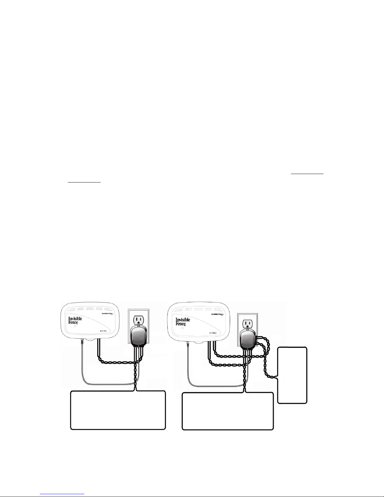
• Invisible Gate, ICT 700, 725 & 801 Systems, install the LP-4100 (use the LP-4200 if
the LP-4100 is not available).
• ICT 750 & 802 Systems, install the LP-4200
• Invisible Gate, ICT 700, 725 & 750 Systems, disregard instructions under Grounding
the System of the Installation and Operations Manual. Refer to the LP Supplemental
section in this manual on page 4.
The LP-4100/4200 Surge Protector must be plugged into a grounded (3-prong) outlet that
is within 5 feet of the Fence Transmitter. ALWAYS use a grounded (3-prong) outlet to
ensure maximum protection. Cutting or removing the 3rd prong from the Surge Protector
or using a 2-prong to 3-prong outlet converter will render the protector ineffective against
surges or spikes. If possible, DO NOT use an AC circuit protected with a GFCI (ground
fault circuit interrupter). Both the Surge Protector and the Fence Transmitter will function
properly, but in rare cases, nearby lightning strikes may cause the GFCI to trip. Without
power, your dog may be vulnerable to escape. You will have to reset the GFCI to restore
power to the system
.
2
www.invisiblefence.com
Page 3
CAUTION:
• To reduce the risk of electrical shock, disconnect power to the
receptacle (outlet) before installing or removing the Surge Protector.
When removing receptacle cover screw, cover may fall across plug pins
or receptacle may become dislodged.
• Use only with a duplex receptacle having a center screw.
• Secure unit in place with screw included with Surge Protector.
Step 1: Turn the power OFF to the outlet that the Surge Protector and Fence
Transmitter will be plugged into.
Step 2: We recommend that, if possible, use the outlet center screw that holds the cover
plate in place to secure the Surge Protector to the outlet. To do this, tape the top of the
cover plate to the wall, and then remove the cover plate center screw. Plug the Surge
Protector into the lower outlet and then secure the cover plate using the longer screw
included with the protector. The screw is for mechanical attachment only and does not
ground the protector. Remove the tape and turn ON the power to the outlet. Be sure to
remove any other protectors and any ground connectors to the transmitter and the
boundary. The Surge Protector gets its ground connection from the AC outlet. Any
additional ground connections will interfere with the protective action and may also
interfere with the operation of the fence transmitter.
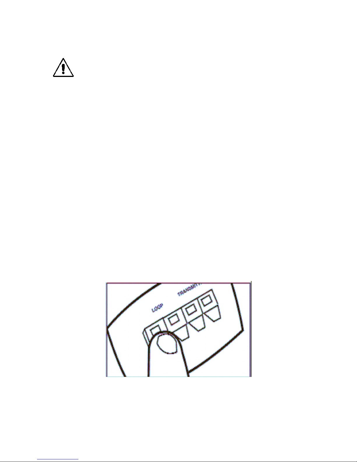
Step 3: Strip the insulation from the ends of the boundary wire, uncovering
approximately 3/8-inch. Insert the stripped ends of the boundary transmitter wires into
the two left red connector holes on the bottom of the Surge Protector labeled “Loop”.
Note: There should be one wire in each connector hole. Depress the plastic tab, then
insert the wires and release the tab.
www.invisiblefence.com
3
Page 4
Step 4: Determine the length of wire needed to pass from the Surge Protector to the
LP3000
Green Ground
Fence Transmitter. Measure and cut 2 lengths of wire, then strip approximately 3/8-inch
of insulation at both ends. Twist the 2 lengths together, with at least 10-12 twists per foot,
so these wires will not send out a signal.
Step 5: Insert the ends of the transmitter wires into the right 2 black connectors at the
bottom of the Surge Protector labeled “Transmitter”.
Note: There should be 1 wire in each connector hole.
Step 6: Insert the opposite stripped ends of the two transmitter wires (from Step 5) into
the connectors on the Fence Transmitter.
CAUTION: Verify the boundary and transmitter wires are connected to the
proper Surge Protector terminals. Damage to both the Surge Protector and your
Fence Transmitter can occur if connections are reversed.
Step 7: Plug in the Fence Transmitter power adapter to the AC outlet on the front of the
Surge Protector. If you have added the Surge Protector to an existing pet containment
system, check the Boundary Width for width and continuity. Adjust as necessary. If the
Surge Protector is being installed with a new pet containment system, follow the
Boundary Width adjustment procedures given in the system’s operating guide. For added
protection for the Surge Protector and Fence Transmitter when unused for long periods of
time, disconnect Loop Boundary Wires and unplug power adapter from the Surge
Protector.
LP Supplemental:
In 2004 Invisible Fence Brand designed a new transient voltage surge suppressor
(TVSS). If your system was installed prior to July of 2004, you may have an older style
lightning protection device. Please follow the instructions below when upgrading to the
LP4100 or LP4200 lightning protection device.
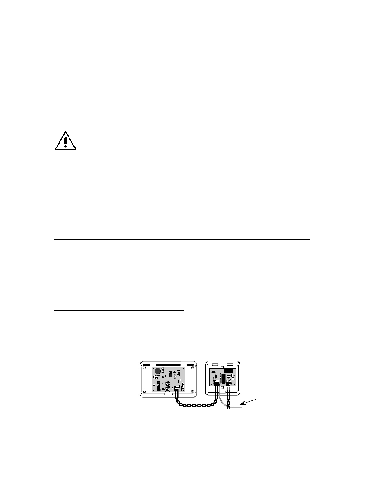
ICT50, ICT75, ICT100, ICT150 and ICT700
1. Remove and discard the green ground wire connecting the LP3000 to the
electrical outlet. (See figure 1)
2. Remove and discard the LP3000 lightning protection device.
3. Refer to steps 2 – 6 of the LP-4100 / LP-4200 manual to complete installation.
4
Figure 1
www.invisiblefence.com
Wire
Page 5
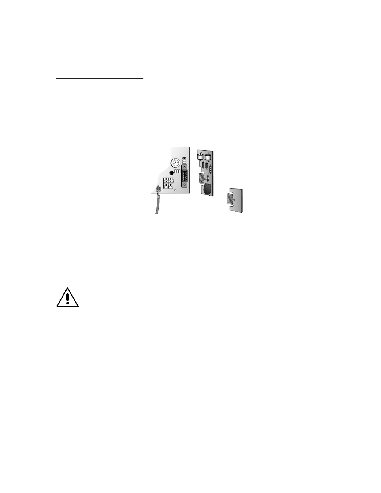
LP-card (Remove)
ICT250, ICT725 and ICT750
1. Remove and discard the green ground wire connecting the circuit board to the
electrical outlet. (See figure 2)
2. Remove and discard the one (ICT725) or two (ICT250 and ICT750) LP-cards
from the blue sockets on the transmitter circuit board. (See figure 2)
3. Insert the jumper-card supplied into each empty blue socket.
4.
Refer to steps 2 – 6 of the LP-4100 / LP-4200 manual to complete installation.
Green
Ground Wire
Figure 2
NOTE: Additional twisted wire may be required when upgrading to this new lightning
protection device. If additional wire was not included in your kit, please notify your local
Invisible Fence Brand dealer.
Jumper-card
(Insert)
CAUTION: Do not install this device if there is not at least 10 meters (30 feet)
or more of wire between the electrical outlet and electrical service panel.
www.invisiblefence.com
5
Page 6

6
www.invisiblefence.com
Page 7

www.invisiblefence.com
7
Page 8

8
800-578-DOGS (USA)
(865) 777-5404 (International)
400-1164/1
© 2008 Radio Systems Corporation
All rights reserved.
www.invisiblefence.com
®
 Loading...