

Invisible QC0144 Installation Manual
Installation Manual
Optical Pulse Transmitter
QC0144
Manual Ref: QC0144
Version: NOV16 1.0

Invisible Systems Limited P a g e | 2
7-9 Beetham Road, Milnthorpe Cumbria, LA7 7QL, England
Phone: 01539 722 520 Email: info@invisible-systems.com
QC0144 Optical Pulse Transmitter Installation Manual
System Concept
Version Tracking
Date
Author
Changes
v 1.0
15/12/2016
Chris Body
RF Transmitters connect to sensors or meters and send data to the infrastructure internet
connected Gateway on site
The Gateway stores and transfers the data to the Realtime Online cloud server over a secure
mobile cellular connection
Realtime Online provides a web based portal of visualisation dashboards, reports, graphs and
transmits out tailored automatic reports and notifications in the event of exceptions

Invisible Systems Limited P a g e | 3
7-9 Beetham Road, Milnthorpe Cumbria, LA7 7QL, England
Phone: 01539 722 520 Email: info@invisible-systems.com
QC0144 Optical Pulse Transmitter Installation Manual
INDEX
Contents
1. Introduction .................................................................................................................................... 4
2. Installation ...................................................................................................................................... 5
3. Sensor Numbering .......................................................................................................................... 7
4. Locating Sensors ............................................................................................................................. 7
5. Checking operation ......................................................................................................................... 9
6. Dashboard configuration .............................................................................................................. 11
7. Meter Validation ........................................................................................................................... 12
8. Appendix 1 – Part Numbers. ......................................................................................................... 13
Document Name
Manual Description
Version
QC0140
Unboxed Ultra RF Gateway Installation Manual
1.0
QC0141
Boxed Ultra RF Gateway Installation Manual
1.0
QC0142
3 Phase Wireless Meter Installation Manual
1.0
QC0143
21-42 Channel Sub-meter Installation Manual
1.0
QC0144
Optical Pulse Transmitter Installation Manual
1.0
Invisible Systems Limited P a g e | 4
7-9 Beetham Road, Milnthorpe Cumbria, LA7 7QL, England
Phone: 01539 722 520 Email: info@invisible-systems.com
QC0144 Optical Pulse Transmitter Installation Manual
1. Introduction
The Optical Pulse Transmitter is a battery powered wireless transmitter capable of capturing pulse
information from metering equipment fitted with a visible flashing pulse output. This sensor uses a
special reader head to count the number of flashes made by the ‘Impulse’ LED found on many
domestic and commercial electricity meters. Since the number of flashes relates to a certain
amount of electricity consumed it can easily be converted into kWh. This sensor uses a modified
version of the pulse sensor. The data collected by the additional wireless gateway can be viewed on
the Realtime Online platform.
Features
A variety of available radio frequency options
Small footprint
Automatic data collection and transmission
Wireless, range of up to 15km line of sight
Battery powered with up to 3-year battery life
None invasive and rapid installation with no cabling required
Technical information
Operating frequency 868MHz (Other frequencies available 915 MHz)
Measurement Accuracy in line with equipment it is connected to.
Operating range up to 15km
Suitable to monitor any device with a visible pulse output
Storage Conditions: 0 °C to +50 °C
Relative Humidity: 25% to 95%
Operating Temperature: 0 °C to 40 °C
Mains powered optional
Applications
Energy Monitoring
Bill validation
Sub-metering
Installations where use of CT/VT’s is not practical.
Invisible Systems Limited P a g e | 5
7-9 Beetham Road, Milnthorpe Cumbria, LA7 7QL, England
Phone: 01539 722 520 Email: info@invisible-systems.com
QC0144 Optical Pulse Transmitter Installation Manual
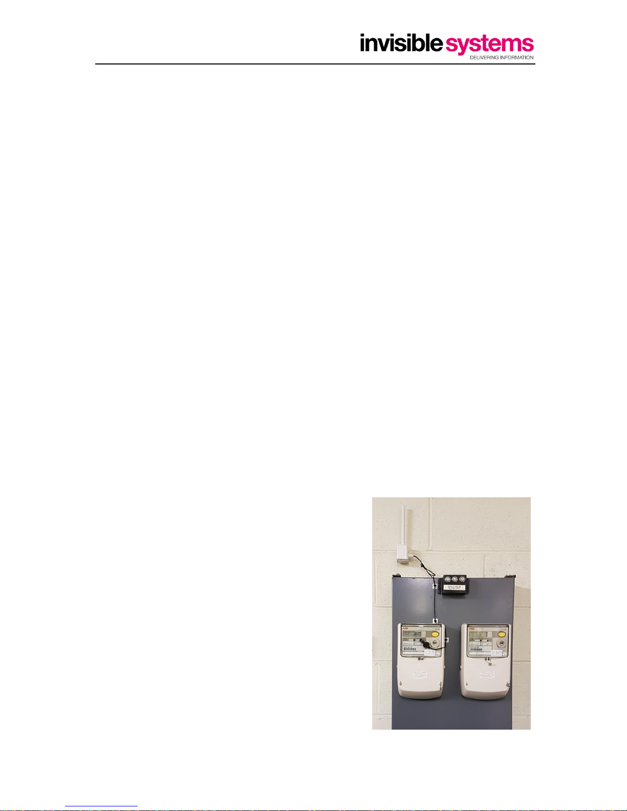
2. Installation
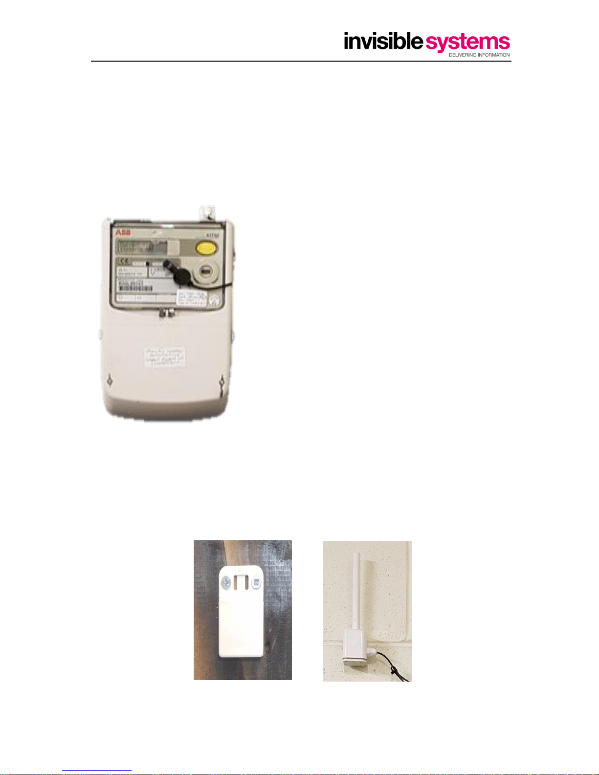
This sensor is supplied with a special sensor head that must be placed exactly over the flashing LED
using the self-adhesive backing.
The LED also needs to be close to or flush with the utility meter case for it to be seen more
accurately, if the light is recessed inside the meter the pulse light may not be seen.
Note that there is a guide mark in the shape of a cross on
the sensor to aid positioning.
The sensor cannot be re-positioned once placed, so ensure
that it is correctly positioned when attaching to the meter.
These sensors are known to perform badly if there is a large
amount of ambient light, so it is preferable to install these
inside a closed cabinet with the transmitter part outside.
Pulse Ranges
0 – 5,000 pulses per hour
Update Rate
Every 7 ½ Mins (8 times per hour).
Most Realtime-Online™ sensors have a unique mounting clip on the battery compartment
which allows the sensor to be installed:
Mounted with screws through the mounting clip.
 Loading...