

Page 1

Paramont CMS AI TSS
User Manual
Contents
Page 2

1 Introduction ...........................................................................................................................................................................................1
1.1 Introduction ...................................................................................................................................................................................1
1.2 Software Architecture ....................................................................................................................................................................1
1.3 System Components ......................................................................................................................................................................1
1.3.1 System ...............................................................................................................................................................................1
1.3.2 Front-end Access ...............................................................................................................................................................2
1.3.3 Background Monitor .........................................................................................................................................................2
1.3.4 Control Center ...................................................................................................................................................................2
1.4 Version ...........................................................................................................................................................................................2
2 Configuration Requirement ..................................................................................................................................................................3
2.1 Software and Hardware Configuration Requirement .....................................................................................................................3
2.1.1 S&H Config Requirement for Control Center ...................................................................................................................3
2.2 Requirement for Firewall ...............................................................................................................................................................3
2.3 Confirm Installation Environment .................................................................................................................................................4
3 Install and Uninstall the Software ................................................................................................ ........................................................5
3.1 Install the software ........................................................................................................................................................................5
3.1.1 Install Server .....................................................................................................................................................................5
3.1.2 Install Client ......................................................................................................................................................................6
3.2 Uninstall Software .........................................................................................................................................................................7
4 Login .......................................................................................................................................................................................................8
4.1 Run Servers ...................................................................................................................................................................................8
4.2 Login .............................................................................................................................................................................................8
4.3 Main Menu Interface Introduction .................................................................................................................................................9
5 Device Management............................................................................................................................................................................. 12
5.1 Add Encoding Device .................................................................................................................................................................. 12
5.1.1 Quickly Add .................................................................................................................................................................... 12
5.1.2 Manually Add .................................................................................................................................................................. 12
5.1.3 Initiatively Report ........................................................................................................................................................... 13
5.2 Modify or Delete Device ............................................................................................................................................................. 14
5.3 Device Upgrade ........................................................................................................................................................................... 14
5.4 Device Setting ............................................................................................................................................................................. 14
5.5 Area Setting ................................................................................................................................................................................. 15
5.6 Channel Group Setting ................................................................................................................................................................ 15
5.7 Add Media Transfer Server ......................................................................................................................................................... 15
5.8 Add Storage Server ...................................................................................................................................................................... 16
6 Intelligent Management ...................................................................................................................................................................... 18
6.1 Temperature Measurement .......................................................................................................................................................... 18
6.1.1 Temperature Settings ....................................................................................................................................................... 18
6.1.2 Live Preview ................................................................................................................................................................... 19
6.1.3 Records Search ................................................................................................................................................................ 20
6.1.4 Statistics .......................................................................................................................................................................... 21
6.2 Face Surveillance ......................................................................................................................................................................... 22
6.2.1 Object Library ................................................................................................................................................................. 22
6.2.2 Task Management ........................................................................................................................................................... 25
6.2.3 Real-Time View .............................................................................................................................................................. 26
6.2.4 Search .............................................................................................................................................................................. 28
6.2.5 Search Image by Image ................................................................................................................................................... 29
6.2.6 Configuration .................................................................................................................................................................. 31
6.2.7 Face Recognition Terminal Access and Configuration .................................................................................................... 32
6.3 Face Greeting .............................................................................................................................................................................. 37
6.4 Face Attendance ........................................................................................................................................................................... 39
6.5 Line Crossing Counting ............................................................................................................................................................... 40
6.5.1 Task Management ........................................................................................................................................................... 40
6.5.2 Real-time Statistics ......................................................................................................................................................... 41
6.5.3 Heat Map ......................................................................................................................................................................... 42
Page 3

6.5.4 Historical Statistics ......................................................................................................................................................... 43
6.5.5 Flow Control ................................................................................................................................................................... 44
6.6 Smart Site View ........................................................................................................................................................................... 45
6.7 Smart View .................................................................................................................................................................................. 46
7 Live View .............................................................................................................................................................................................. 47
7.1 Live View .................................................................................................................................................................................... 47
7.1.1 View Mode Setting .......................................................................................................................................................... 48
7.1.2 Monitoring Point View .................................................................................................................................................... 48
7.1.3 Channel Group View ....................................................................................................................................................... 49
7.1.4 Plan View ........................................................................................................................................................................ 50
7.2 View Control ............................................................................................................................................................................... 51
7.3 Snapshot ...................................................................................................................................................................................... 52
7.4 Multi-Screen View ....................................................................................................................................................................... 52
7.5 Talkback ................................................................................................................................ ...................................................... 53
7.6 PTZ Control ................................................................................................................................................................................. 53
7.7 Audio Broadcast .......................................................................................................................................................................... 54
8 Record & Playback ................................................................ .............................................................................................................. 55
8.1 Record Configuration .................................................................................................................................................................. 55
8.1.1 Manual Recording ........................................................................................................................................................... 55
8.1.2 Schedule Recording ........................................................................................................................................................ 55
8.1.3 Alarm Linkage Recording ............................................................................................................................................... 56
8.2 Record Playback .......................................................................................................................................................................... 56
8.2.1 Instant Playback .............................................................................................................................................................. 58
8.2.2 Synchronous Playback .................................................................................................................................................... 59
8.2.3 Asynchronous Playback .................................................................................................................................................. 59
8.2.4 Playback by Time Slice ................................................................................................................................................... 59
8.2.5 Playback by Event ........................................................................................................................................................... 61
8.2.6 Playback by Tag .............................................................................................................................................................. 61
8.3 Backup ......................................................................................................................................................................................... 62
8.4 Search Picture .............................................................................................................................................................................. 62
9 Alarm Management ............................................................................................................................................................................. 64
9.1 Alarm Server Configuration ........................................................................................................................................................ 64
9.2 Alarm Configuration.................................................................................................................................................................... 64
9.3 SOP Settings ................................................................................................................................................................................ 65
9.4 Alarm View ................................................................................................................................................................................. 66
9.5 Alarm Log ................................................................................................................................................................................... 67
10 E-Map ................................................................................................................................................................................................... 69
10.1 E-Map Settings ............................................................................................................................................................................ 69
10.1.1 Create E-Map .................................................................................................................................................................. 69
10.1.2 Add Hotspot .................................................................................................................................................................... 69
10.1.3 E-Map Monitoring .......................................................................................................................................................... 69
11 TV Wall ................................................................................................................................................................................................. 71
11.1 Add TV Wall Server .................................................................................................................................................................... 71
11.2 Add Decoder ................................................................................................................................................................................ 71
11.2.1 Create and Connect Decoder ........................................................................................................................................... 71
11.3 TV Wall Management .................................................................................................................................................................. 72
11.3.1 TV Wall Settings ............................................................................................................................................................. 72
11.3.2 TV Wall View .................................................................................................................................................................. 76
11.3.3 Decoder Input .................................................................................................................................................................. 81
11.3.4 Playback .......................................................................................................................................................................... 82
11.3.5 Task Setting of TV Wall ................................................................................................ .................................................. 83
11.3.6 TV Wall System Configuration ....................................................................................................................................... 84
12 Account and Permission ...................................................................................................................................................................... 86
12.1 Create Account ............................................................................................................................................................................ 86
12.2 User Permission Settings ............................................................................................................................................................. 86
13 Operation and Maintenance Management ........................................................................................................................................ 88
Page 4

13.1 Check and Export Log ................................................................................................................................................................. 88
13.2 Backup and Restore Configuration .............................................................................................................................................. 88
13.3 Viewing Online Status ................................................................................................................................................................. 88
13.4 Viewing Status Log ..................................................................................................................................................................... 89
14 Local Configuration............................................................................................................................................................................. 90
14.1 Record and Snapshot Settings ..................................................................................................................................................... 90
14.2 Local Settings .............................................................................................................................................................................. 90
14.3 Overload Settings ........................................................................................................................................................................ 91
14.4 Alarm View Settings .................................................................................................................................................................... 91
14.5 OSD Position Configuration ........................................................................................................................................................ 91
14.6 System Configuration .................................................................................................................................................................. 91
14.7 Audio Uploading ......................................................................................................................................................................... 92
15 Parking Lot Management ................................................................................................................................................................... 93
15.1 System Settings ........................................................................................................................................................................... 93
15.2 Vehicle Management ................................................................................................................................................................... 94
15.3 Vehicle Monitoring ...................................................................................................................................................................... 95
15.4 Search .......................................................................................................................................................................................... 95
15.5 Parking Overstaying .................................................................................................................................................................... 96
15.6 Backlist Vehicle ........................................................................................................................................................................... 96
16 Web Client ............................................................................................................................................................................................ 98
16.1 Operating Environment of Web Client ........................................................................................................................................ 98
16.2 Start IE Client .............................................................................................................................................................................. 98
17 Mobile APP Surveillance ..................................................................................................................................................................... 99
17.1 Live ........................................................................................................................................................................................... 100
17.2 Remote Playback ....................................................................................................................................................................... 101
17.3 Alarm Information ..................................................................................................................................................................... 102
18 Troubleshooting ................................................................................................................................................................................. 103
Page 5
1.1 Introduction
Application Layer
Business Layer
Platform Layer
Access Layer
C/S Client
B/S Client
Mobile Phone
Client
The Third Party
System
Decode to
TV Wall
Record
Storage
Record
Playback
E-Map
Alarm
Linkage
Voice
Talk
Service
IPC
NVR
TVI-DVR
AHD-DVR
Analog
DVR
Client
CMS Standard is a brand new video surveillance management platform released by our company, seamless access to all products of our
company and encoding devices of the famous manufacturers in the industry . With the powerful capability of
video surveillance management, real-time preview, record storage, record playback, record download, alarm linkage, decoding on TV Wall,
keyboard control, vehicle entrance and exit management as well as intelligent analytics are supported. Additionally, due to its open system
architecture, its SDK/OCX can be provided to the third party for secondary development. Therefore, CMS Standard can meet the client’s
demands of centralized video management and can be widely used in the video surveillance of industrial park, education, banking, chain
stores and buildings.
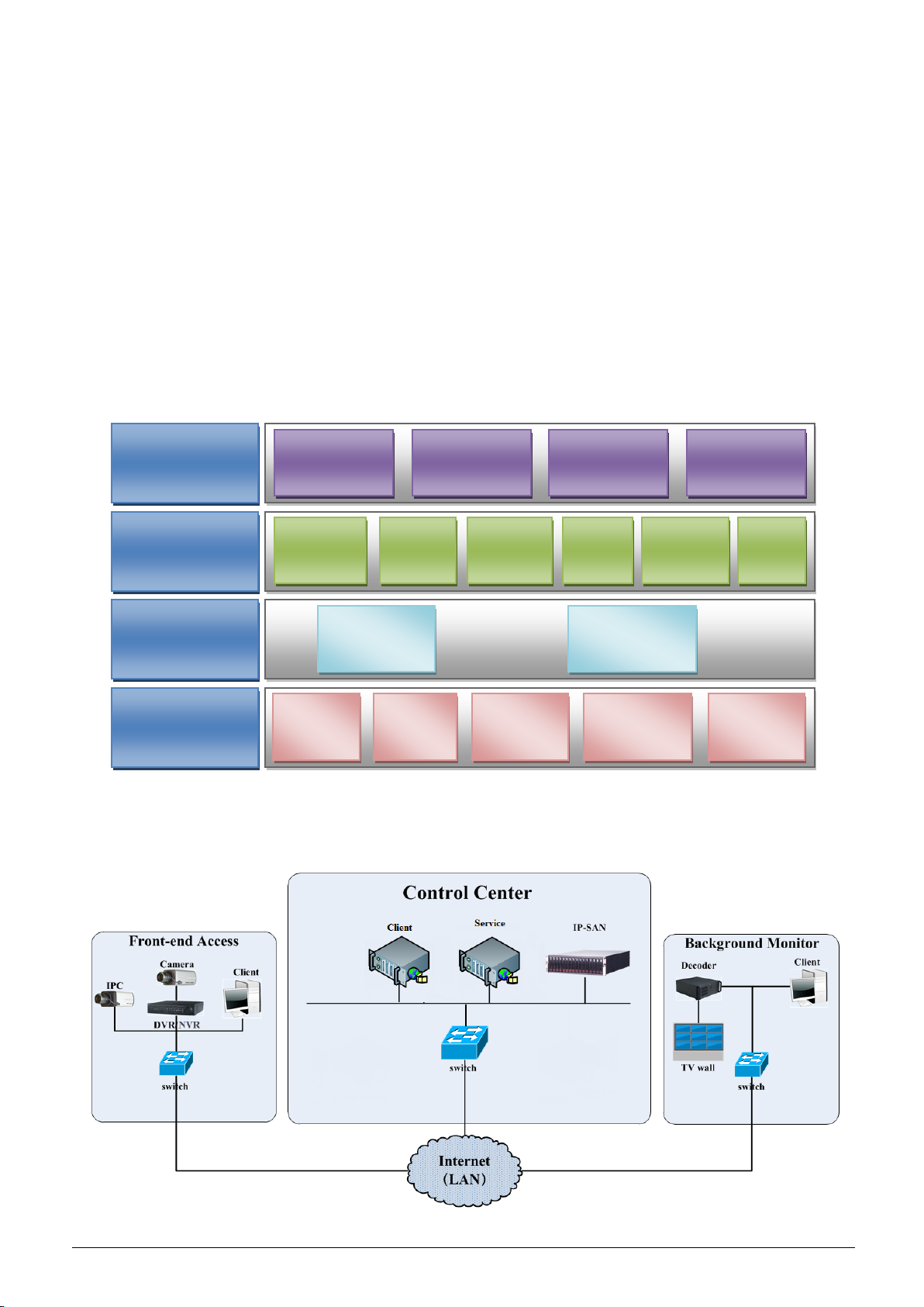
1.2 Software Architecture
1.3 System Components
1.3.1 System
1
Page 6

1.3.2 Front-end Access
Signal access on trial
Max signal access
32 channels video signals
30000-ch video signals
Front-end devices include IPC, DVR and NVR.
You need to connect monitor devices such as IPC, DVR and NVR to internet through hubs or routers accessed by Cat5 or Cat5e
cables (less than 100 meters) or optical fiber.
Run monitor client through local PC to configure the local video monitor, monitor devices and so on.
1.3.3 Background Monitor
Background monitors include TV Wall, Monitor, etc.
You can set up the real-time image of display devices, these display devices including TV-Wall (decoding images to show on the
TV-Wall through video decoder), digital display screen and so on.
Run monitor client through local PC to view, playback and remotely configure and manage the real-time video of front-end monitor
devices.
1.3.4 Control Center
Realize various services, such as, video transmission, recording, decoding on TV wall, etc.
Add IP-SAN storage array to realize centralized storage.
Connect servers and IP-SAN storage array to internet through switches.
Set up IP addresses in accordance with the actual situation.
1.4 Version
2
Page 7

2 Configuration Requirement
No.
components
Recommendation for hardware
configuration
Recommendation for software
configuration
Number
1
Monitor Client
Inter(R) Core(TM)i3 3.40GHz or
above/4GBMemor DDR3/NV
GT430 or AMD HD6570 or above
/500GB SATA/1000M NICs
Windows 7 SP1 32bit/64bit
Professional/Ultimate
Windows 8 32bit/64bit Professional
Windows 10 32bit/64bit Professional
As needed
2
Authentication
Server
Inter(R) Core(TM)i3 3.40GHz or
above/4GBMemor DDR3/NV
GT430 or AMD HD6570 or above
/500GB SATA/1000M NICs
Windows Server 2016-64bit
/Windows Server 2012-64bit
/Windows Server 2008(32bit\64bit)
/Windows Server 2003(32bit\64bit)
It also can be run in
the PC of Monitor
Client.
3
Intelligent Server
Inter(R) Core(TM)i5 7500 3.0GHz
or above/
4GBMemory/500GB
SATA/2×1000M NICs
Windows Server 2016-64bit
/Windows Server 2012-64bit
/Windows Server 2008(32bit\64bit)
/Windows Server 2003(32bit\64bit)
As needed
No.
components
Recommendation for hardware
configuration
Recommendation for software
configuration
Number
1
Monitor
Client-64bit
Inter(R) Core(TM) i5 7500 3.0GHz
or above /16GB DDR3/Intel HD
Graphics 530 2GB or above/
NVIDIA GeForce GTX 1060 6GB
or above,(multi-screen : 2GB
GDDR5memory)/500GB
SATA/Gigabit NIC
Windows 7 SP1 64bit
Professional/Ultimate
Windows 8 64bit Professional
Windows 10 64bit Professional
As needed
2.1 Software and Hardware Configuration Requirement
2.1.1 S&H Config Requirement for Control Center
CMS
The recommended 64-bit hardware configurations are as follows.
CMS
2.2 Requirement for Firewall
In order to ensure the network security, it is necessary for the system to set up firewall. All monitor ports shall be opened in the installed
servers. The open ports are as follows:
3
Page 8

Server
Port Type
Port
Authentication Server
Internal Port
6003
Configuration Server
Internal Port
7002
HTTP Server
Service Port
8080
Media Transfer Server
Internal Port
6006
Auto Report Port
2009
Storage Server
(windows version /IP-SAN)
Internal Port
6009
Intelligent Server
Internal Port
6069
Alarm Server
Internal Port
6033
TV Wall Server
Internal Port
6036
Note: The above-mentioned ports are the default internal ports of servers. If all these ports are modified, these open ports shall be modified
Item
Checkup Standard
Hardware
Check whether the hardware meets the standard required. (including CPU, memory, HDD, etc.)
Software
Check whether the software meets the standard required. (including the type and version of the operation
Front-end device
Check whether the device access is normal.
Firewall setup
Check whether those open ports of firewall meet the standard required.
Network
Check whether the networks of front-end devices and center equipments are normal.
TCP/IP config
Check whether the settings of IP address, subnet mask, gateway and DNS correct.
accordingly in the firewall configuration.
2.3 Confirm Installation Environment
system, CMS version, etc.)
4
Page 9
3 Install and Uninstall the Software
3.1 Install the software
There are two setups-setup of Server and Client.
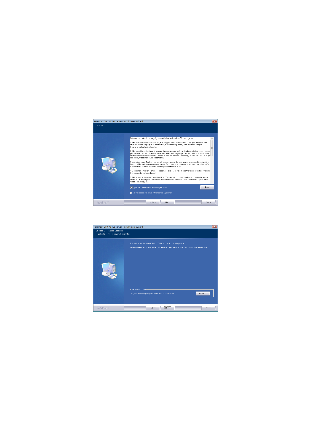
3.1.1 Install Server
1) Double click ―Paramont CMS AI TSS server.exe‖.
2) Click [I accept the terms of the license agreement] and then click [Next].
3) Click [Browse] to select the installation location and then click [Next]
4) Check ―Launch Software‖ as needed and then click [Finish]‖.
5
Page 10
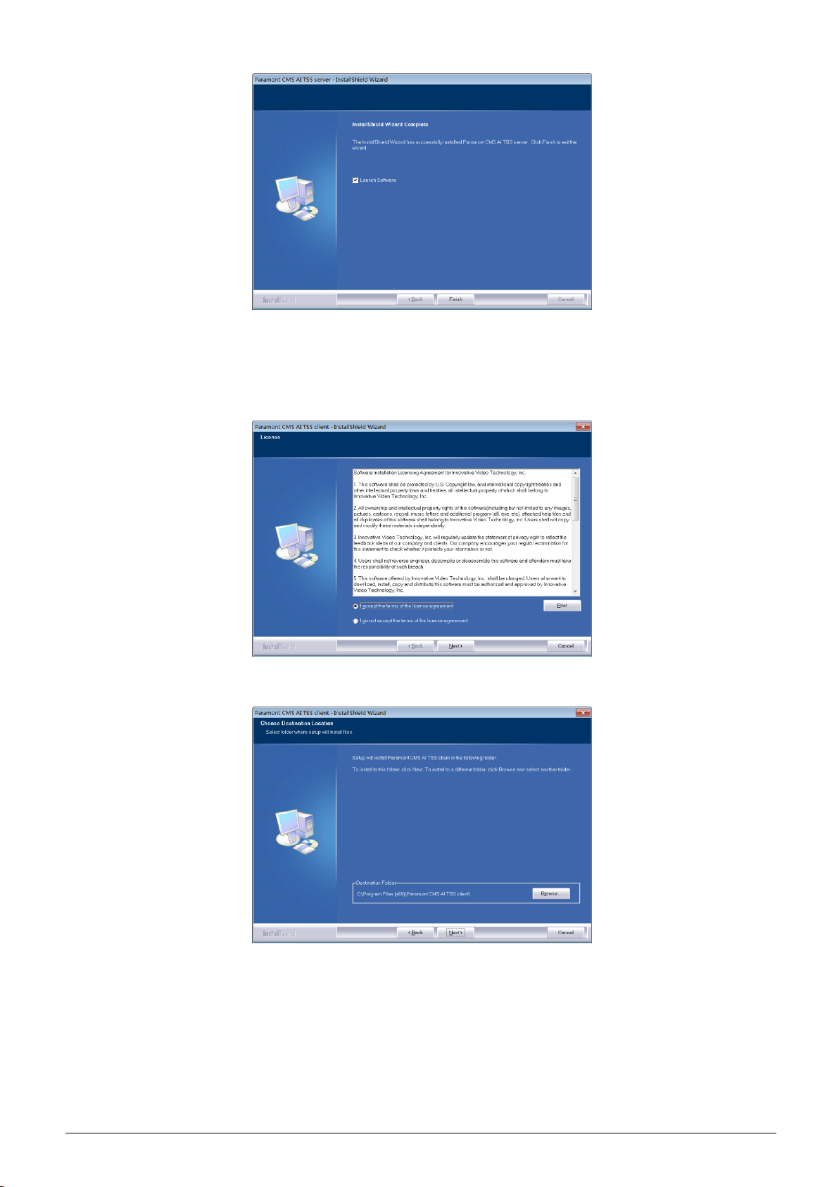
3.1.2 Install Client
1) Double click ―Paramont CMS AI TSS client.exe‖.
2) Click [I accept the terms of the license agreement] and then click [Next].
3) Click [Browse] to select the installation location and then click [Next].
4) Check ―Launch Software‖ as needed and then click [Finish]‖.
6
Page 11
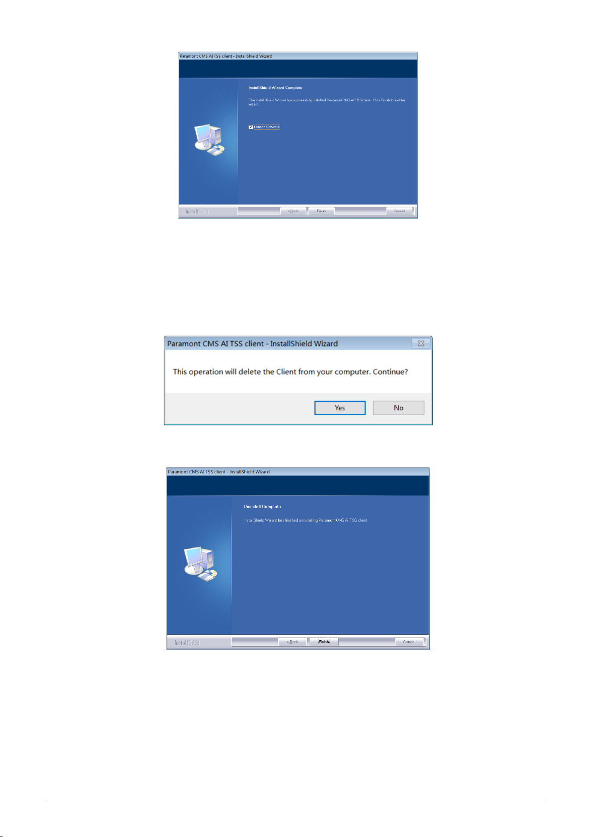
3.2 Uninstall Software
If the new version needs to be installed or there is no need to use this software, this software can be uninstalled. It is
strongly recommended to back up the configuration data before installing the new version of CMS.
The uninstallation steps of the Server are similar to the uninstallation of the client.
Click ―Start‖ All Programs CMS ServerUninstall to pop up the following wizard. Click ―Yes‖ to confirm.
Then click ―Finish‖ button to completely uninstall Authentication Server.
7
Page 12
4 Login
4.1 Run Servers
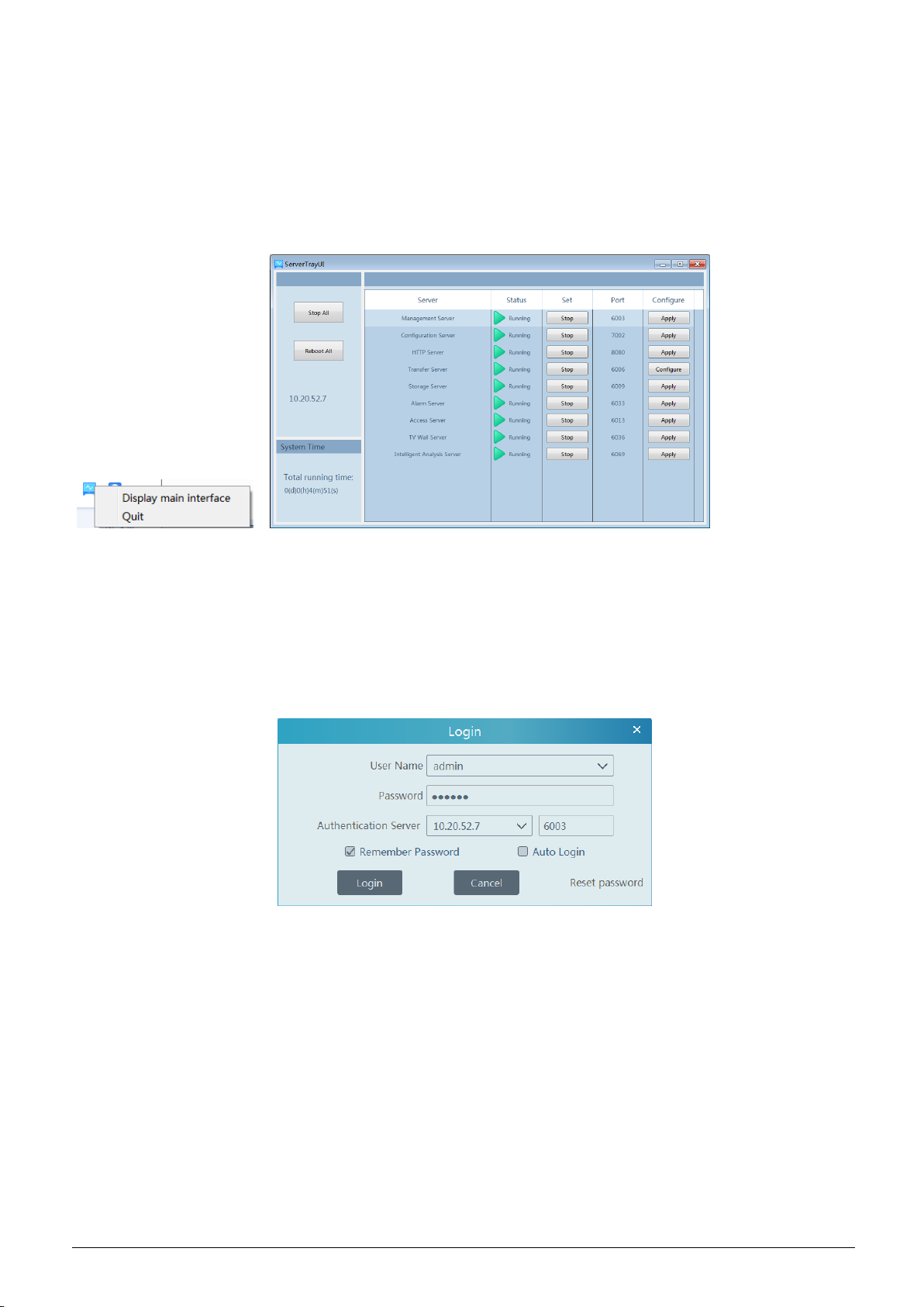
Before logging onto the client, please ensure all servers are working normally. Having been installed successfully for the first time, the
server tray will minimize on the taskbar of the computer. Double click the server tray icon to pop up the server tray interface. You can also
right click the server tray icon and select ―Display main interface to pop up the server tray interface as shown below.
The working status and port can be checked from the server tray. All servers can be stopped and restarted. Additionally, all server ports can
be modified as needed. Click the corresponding port number to modify it and the modified port can be saved automatically after you move
your mouse to another place.
Please set up according to the actual network.
4.2 Login
Double click the shortcut icon of ―Monitor Client‖ to run the software as shown below.
① Enter username and password (the default username is admin; the default password is 123456).
② Enter the IP address and port of the authentication server (the default port is 6003).
Check ―Remember Password‖ or ―Auto Login‖ as needed.
③ Click [Login].
If you forget the password, please click ―Reset password‖. Then a small window will appear. You can reset the password by answering the
pre-defined questions.
If this is the first time for you to log in, it is recommended to set the security questions/answers.
8
Page 13
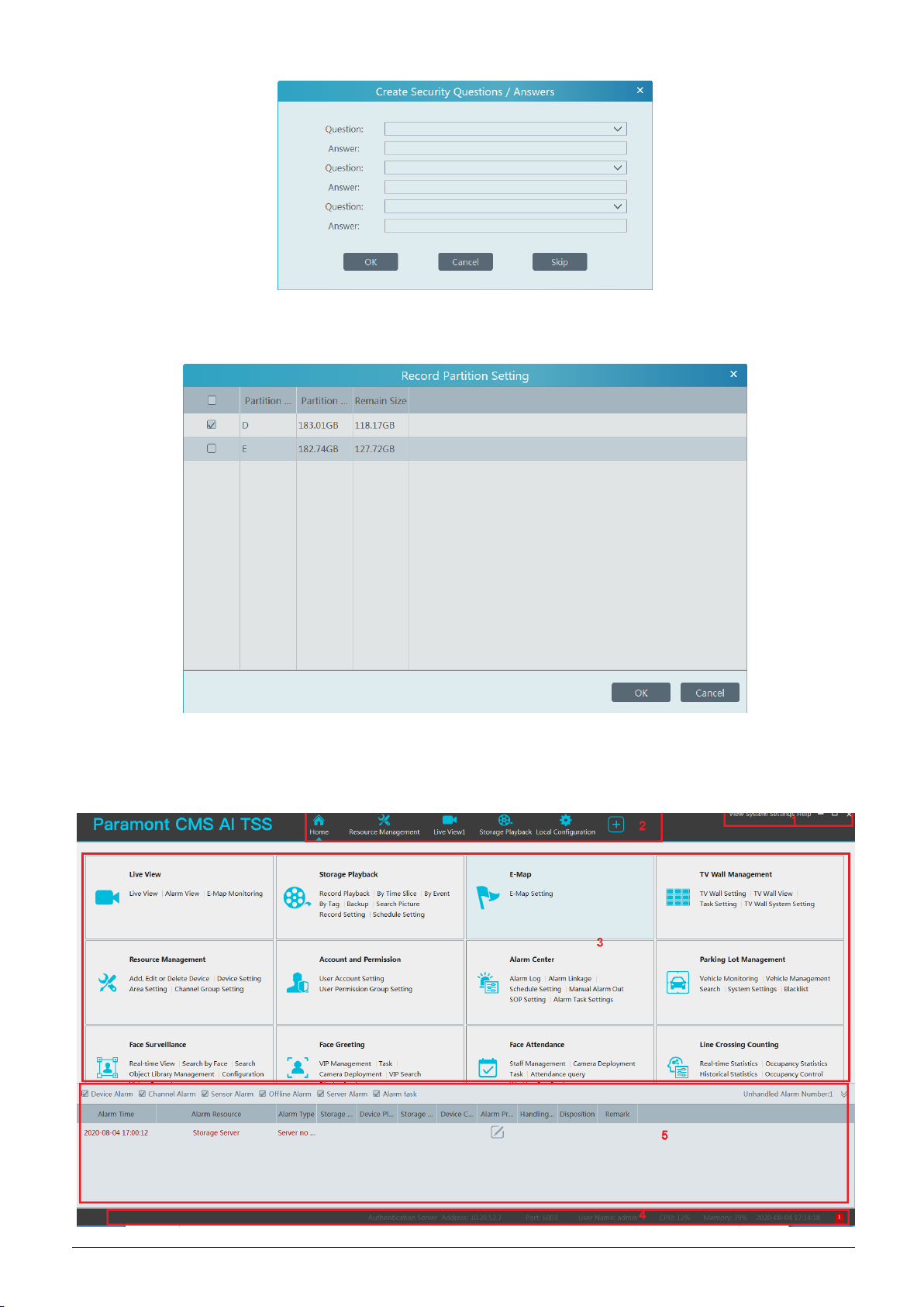
After you log in, a record partition setting box will pop up. Please select the desired record storage location. Then click [OK] to save the
settings.
4.3 Main Menu Interface Introduction
9
Page 14

There are five parts in the main menu interface. The descriptions of each part are as shown below.
No.
Description
No.
Description
1
Menu Bar
4
Status Bar
2
Tab Bar
5
Alarm Information Bar
3
Functional Areas
Menu
Description
View
―Live View‖, ―Edit live view‖, ―Change to home page‖, ―Change to smart view page‖, ―Change to smart
site page‖.
System
Including ―Live View‖, ―Record Playback‖, ―E-Map‖, ―TV Wall Management‖, Resource Management‖,
―Account and Permission‖, ―Alarm Center‖ ―Operation and Maintenance Management‖, ―Face
Surveillance‖, ―Face Greeting‖, ―Line Crossing Counting‖, etc.
Help
Menu
Description
Live View
To view live images and to record, snapshot and talk, etc.
Record
Playback
To remotely play the local records or back up records.
E-Map
To manage and display maps, hot spots, etc.
TV Wall
Management
To set TV wall and decoding videos on TV Walls
Resource
Management
To add, modify or delete areas, devices or servers.
Account and
Permission
To add, modify or delete user account and set permissions for these accounts.
Alarm Center
To set alarm linkage and schedule; To search alarm logs.
Face
Surveillance
To recognize, compare or search face.
Face Greeting
To welcome visitors based on face recognition technology
Face Attendance
To help to manage staff attendance based on face recognition technology
Temperature
Measurement
To view the statistics of pass-by counts(today/total), non –mask counts(today/total), over temp
counts(today/total); To search records based on temperature/mask detection;
Parking Lot
Management
To manage vehicles in the parking lot
Line Crossing
Counting
To monitor and analyze people/vehicle flow in real time
Operation and
Maintenance
Management
To search, export and maintain logs.
Local
Configuration
To set record path, snapshot path, system startup and maintenance, overload and alarm view.
Functional
Selection
To select common functions displayed on the home page.
Menu Bar
Tab Bar
Including ―User Manual‖, ―Register license‖ and ―About CMS‖
Functional area
: Click it to view more menus.
10
Page 15

Other buttons:
Button
Description
Click it to hide the interface.
Click it to zoom in or out the interface.
Click to exit the software.
Click it to add the live view page.
When the tab pages exceed the applicable numbers, this icon will display. Click it to view the hidden
tabs.
11
Page 16
5 Device Management
5.1 Add Encoding Device
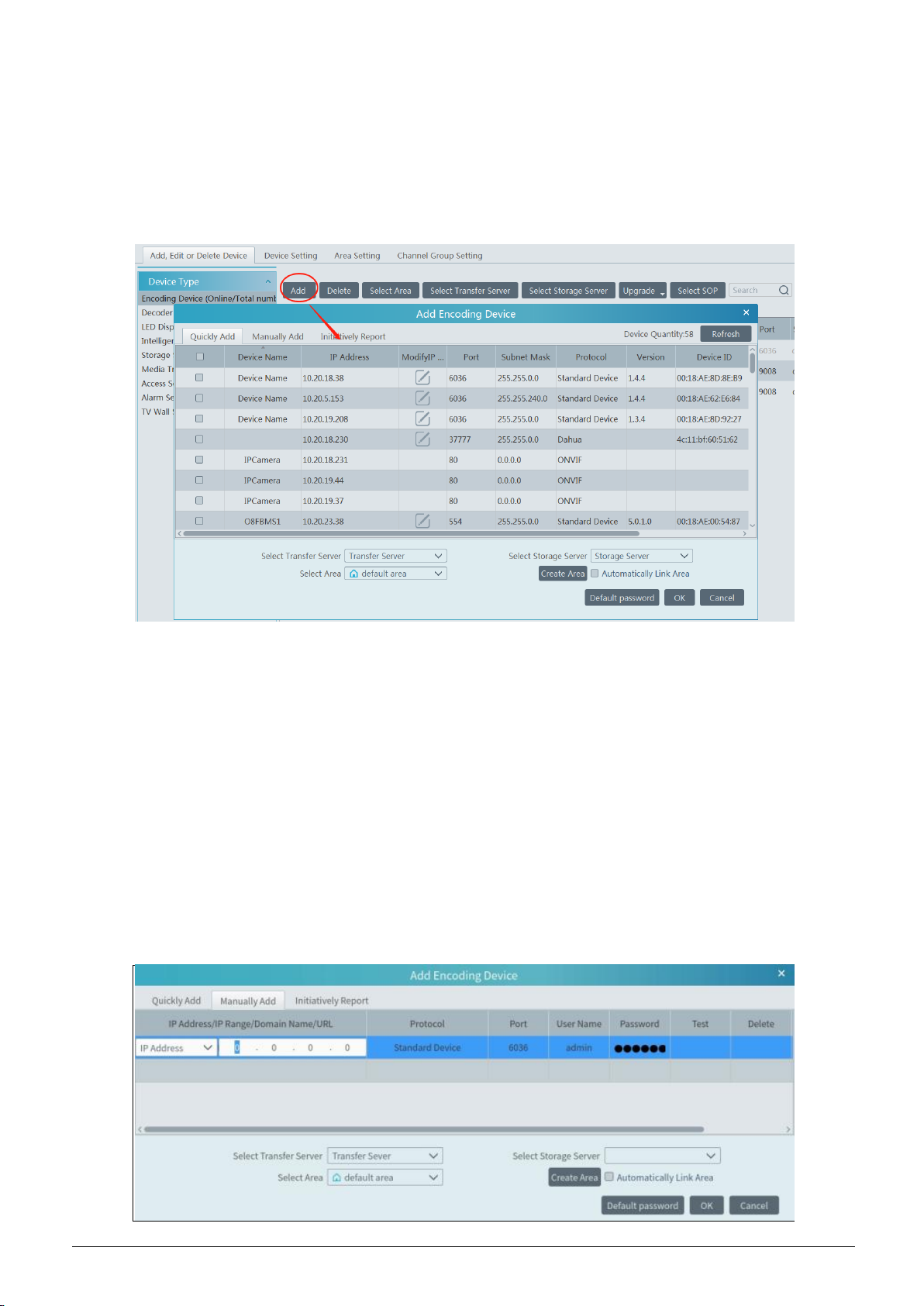
In the main menu interface, click ―Add, Edit or Delete Device‖ to go to the following interface as shown below.
Then click ―Add‖ to add devices. You can add multiply devices in this interface, such as face detection IPC, face recognition
IPC/NVR/box, face recognition terminal, perimeter alert IPC, ANPR camera, etc.
5.1.1 Quickly Add
Click [Refresh] to quickly search devices in the same local network as shown below. Check the device and allocate the transfer server,
storage server, area for it. After that, click [OK].
Click ―Default password‖ to set the default username and password of the devices from different manufacturers. The default username of
the standard device is ―admin and the default password of the standard device is ―123456‖.
Note: * The default media transfer server and storage server can be selected when adding devices. Users can also create new media
transfer server and storage server in advance (see Add Media Transfer Server and Add Storage Server).
* Area must be set up before adding devices. Click [Add Area] to create an area (See Area Setting).
5.1.2 Manually Add
12
Page 17
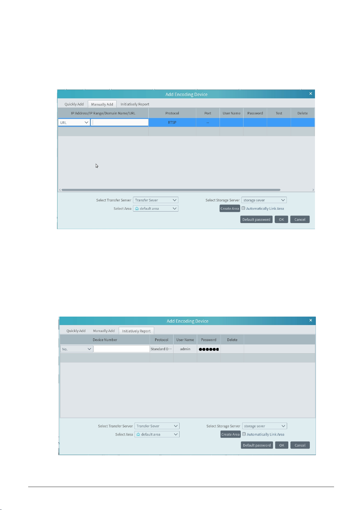
① Enter IP address/IP range/domain name, username and password and choose protocol type.
② Click [Test] to test whether the device is connected successfully or not.
③ Select transfer server, storage server and area and then click [OK].
Devices can be added in batch by adding IP range.
If ―URL‖ is selected, you shall add the device via RTSP protocol. Enter the URL, username and password of the device and then click
[Test] to test whether the device is connected successfully or not.
How to get URL?
Here we take the IPC of our company for example. Log in to the web client of the IPC and then go to ―Config‖ ―Network‖ ―RTSP‖
interface to configure RTSP.
The default RTSP port is 554 and the URL format is ―rtsp://IP or domain name:port/profile1‖. For example:
rtsp://192.168.1.1:554/profile1. Profile1stands for main stream; profile2 stands for sub stream; profile3 stands for the third stream.
The URL of the device of other companies, please get the URL from its web client or the third-party tools (like ODM).
5.1.3 Initiatively Report
Select the ―Initiatively Report‖ Tab to see the following interface.
① Enter the device ID set in the DVR/NVR or IP camera and choose the protocol.
If the DVR/NVR is needed to add, please go to NetworkPlatform Access interface of the DVR/NVR. Check ―Enable‖, enter the IP
13
Page 18
address and port (default 2009) of the CMS and then set the device number of the DVR/NVR.
If the IP camera is needed to add, please go to Network ConfigurationServer Configuration of the IP camera. Check ―Do you want
IPcamera to connect Server‖, enter the IP address and port (default 2009) of the CMS and then set the device number of the IP
camera.
② Select the transfer server, storage server, area and then click [OK].
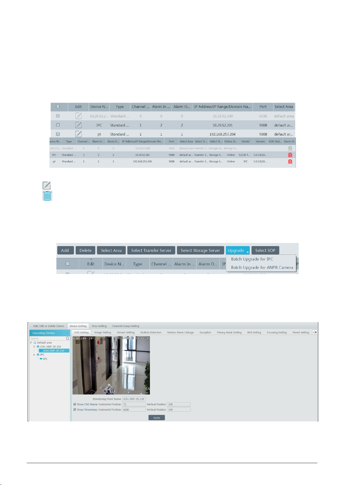
5.2 Modify or Delete Device
After devices are added successfully, they will be listed as below.
The device channel number, alarm status, online status and record status can be viewed from the above table.
Click to modify the IP address, port and so on.
Click to delete the added device. Check the devices and click [Delete] to delete devices in bulk.
5.3 Device Upgrade
In the ―Add, Edit or Delete Device‖ interface, check the devices you want to upgrade and then click [Upgrade]. In the dropdown list, select
―Batch Upgrade for IPC‖ or ―Batch Upgrade for ANPR Camera‖ to upgrade the firmware of IPC/ANPR Camera.
Note: When multiple IPCs are upgraded simultaneously, the selected IPCs must be the same series.
5.4 Device Setting
Go to HomeDevice Setting interface as shown below. In this interface, the parameters of the device can be set up.
Different devices have different menus. Please configure the device according to the corresponding user manual.
14
Page 19
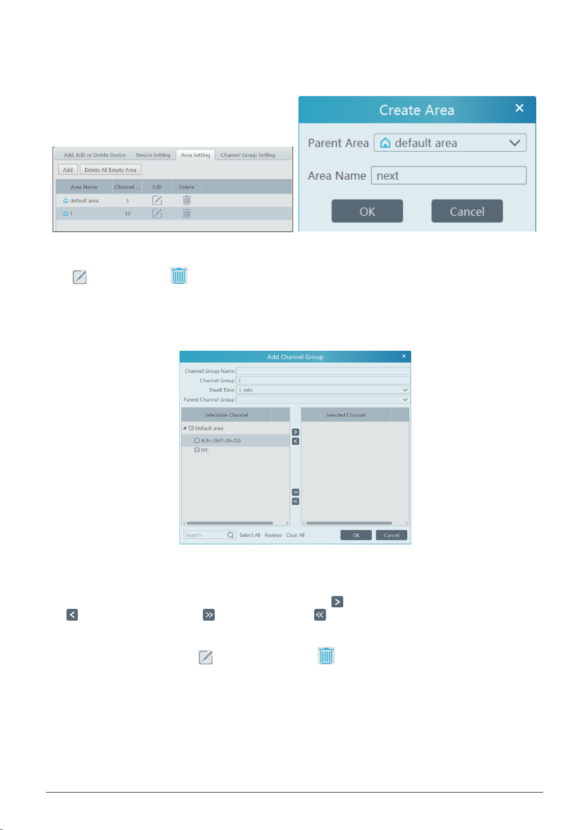
5.5 Area Setting
Go to Home Area Setting interface as shown below.
Click [Add] to go to Area adding interface. Enter area name to create parent area. Then click [OK] to save the settings. To create sub area,
click [Add], choose the parent area, enter the area name and click [OK].
Click to modify area; click to delete area.
5.6 Channel Group Setting
Go to Home Channel Group Setting interface as shown below.
① Click [Add].
② Enter channel group name, channel group and dwell time.
③ Select the parent channel group.
④ Add channels to the channel group. Check the desired channels and click to add channels; choose the selected channel and click
to remove those channels; Click to add all channels; click to remove all selected channels. You can also enter the key
words to search the channels and then select them.
⑤ Click [Ok] to save the settings.
Select the added channel group and click to modify the channel; click to delete the channel.
5.7 Add Media Transfer Server
Media transfer server is in charge of the video signal reception of the front-end devices (like IPC) and transfers the signal to the client to
view or to the storage server to record. The command of viewing the video of the front-end devices sent by the client or storage server is
transferred by the media transfer server to the front-end devices.
Go to HomeAdd, Edit or Delete DeviceMedia Transfer Server.
15
Page 20
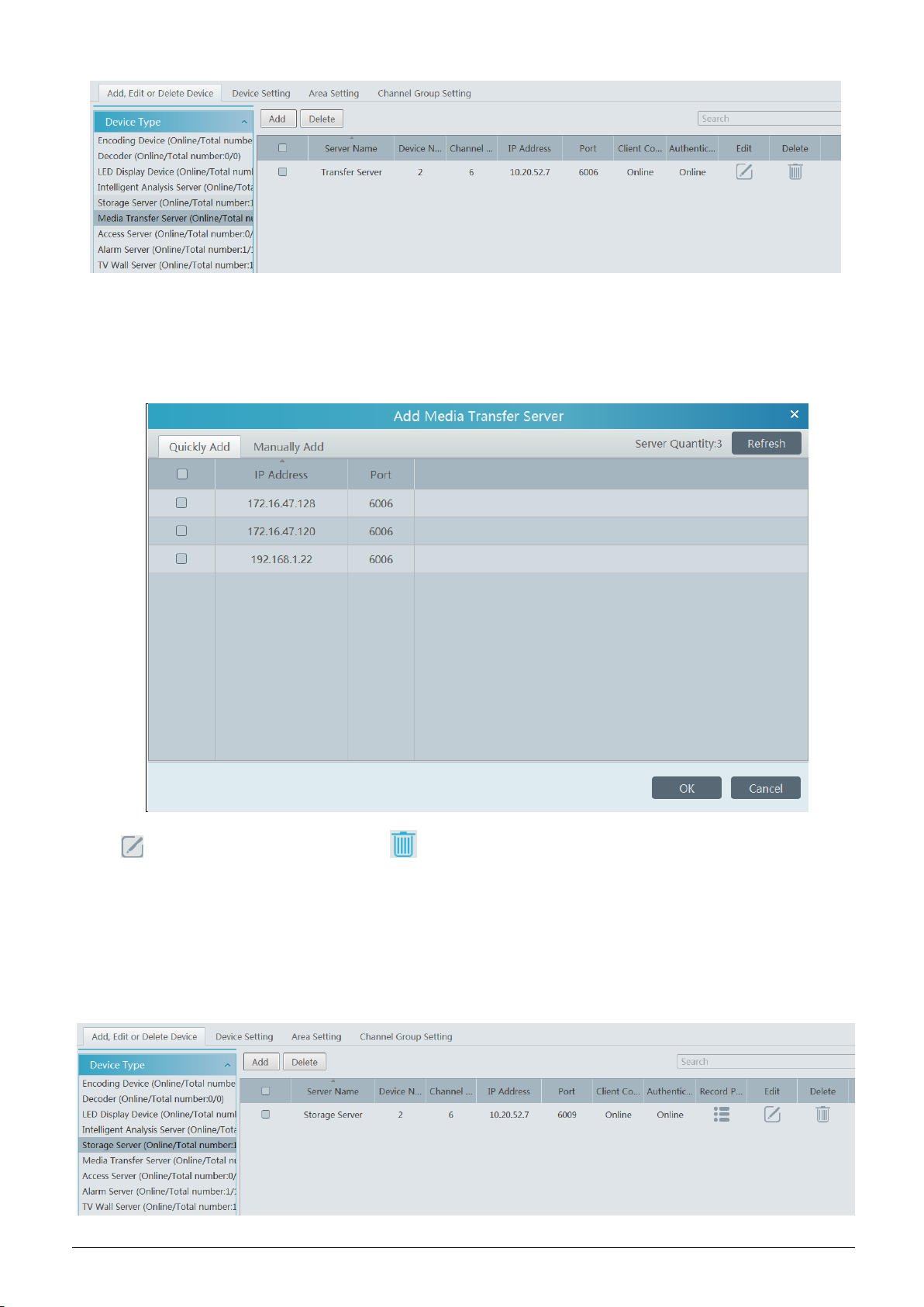
Click [Add] to go to media transfer server addition interface. Users can quickly add or manually add media transfer servers.
Select the ―Quickly Add‖ tab and click [Refresh] to quickly search servers in the same local network. Check the desired servers and click
[OK] to save the settings.
Select the ―Manually Add‖ tab to go to the media transfer server adding interface. Enter the server name, IP address and port and click
[OK] to save the settings.
Click to modify the media transfer server; click to delete the media transfer server.
5.8 Add Storage Server
Storage server is in charge of the storage of record information, including the information of schedule record, record based on motion
alarm, sensor alarm, smart detection alarm (like object removal detection, line crossing detection, etc.), responding to the search and
playback of all storage data. It also supports self-defined storage path settings and IP-SAN access.
Go to HomeAdd, Edit or Delete Device.
16
Page 21
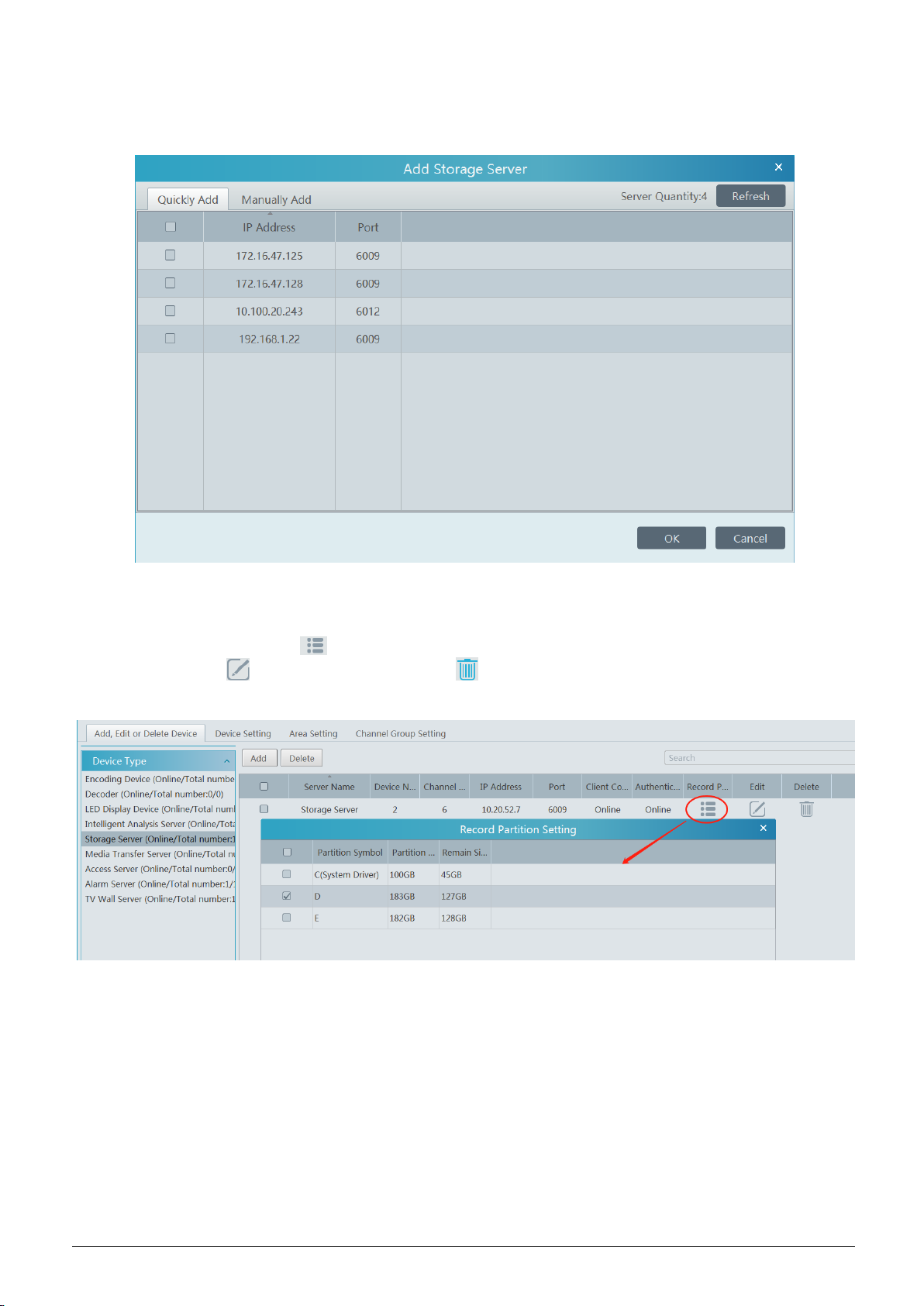
Click [Add] to go to storage server adding interface. Users can quickly add or manually add storage servers.
Select the ―Quickly Add‖ tab and click [Refresh] to quickly search servers in the same local network. Check the desired servers and click
[OK] to save the settings.
Select the ―Manually Add‖ tab to go to the storage server adding interface. Enter the server name, IP address and port and click [OK] to
save the settings.
After the storage server is added, click to set record partition. In the record partition setting interface, select the disk and click [OK]
to save the settings. Click to modify the storage server; click to delete the storage server.
17
Page 22
6 Intelligent Management
Before using intelligent functions, please confirm the intelligent analysis server has been already created and it is online.
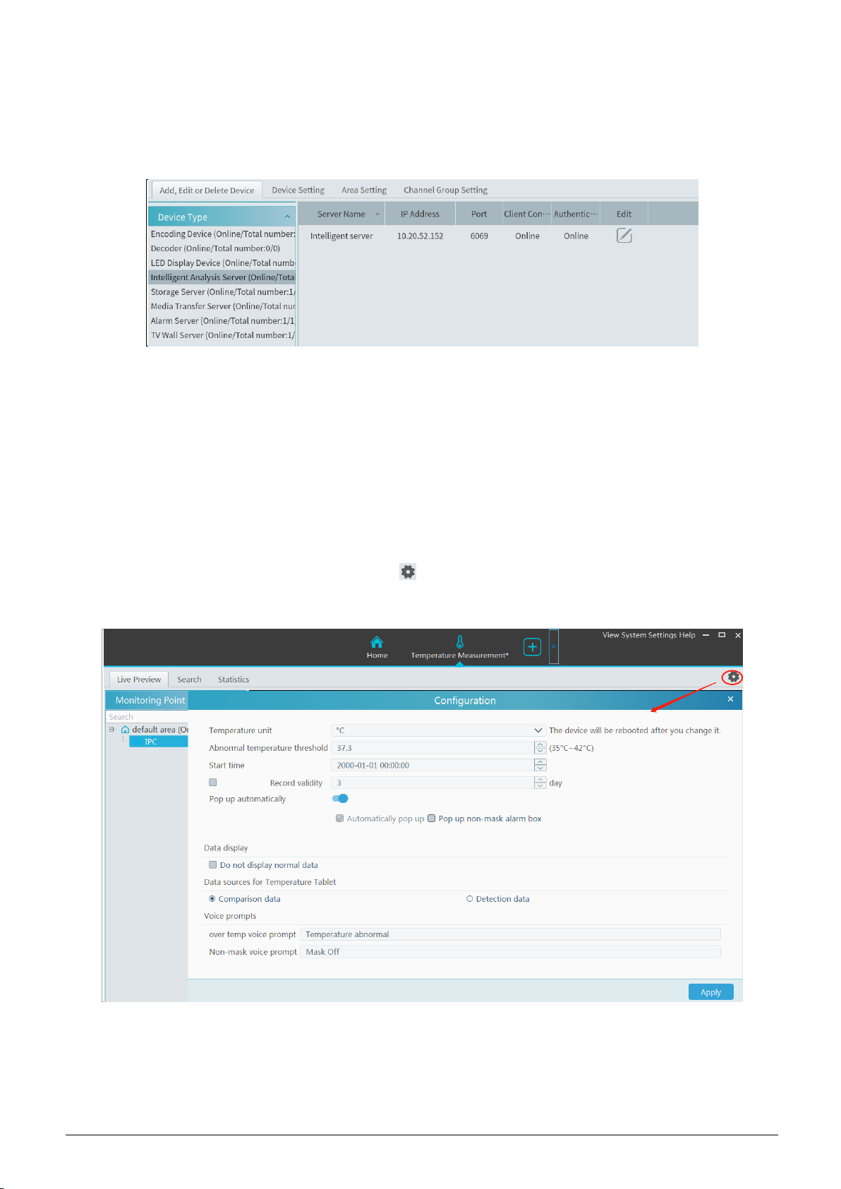
Go to HomeResource ManagementIntelligent Analysis Server. There is a default intelligent analysis server. Please make sure the
server is online.
Users can also add a new intelligent analysis server. Click [Add] and then click [Refresh] to quickly search the server in the same local
network. Click the ―Manually Add‖ tab to manually add the IP address and port of the server.
6.1 Temperature Measurement
Before start, please add thermal network cameras or temperature measurement terminal first. (Click ―Resource Management‖ ―Add,
Edit or Delete Device‖ ―Encoding Device‖ ―Add‖)
6.1.1 Temperature Settings
1. Click HomeTemperature MeasurementLive Preview to go to the following interface.
2. Set the temperature unit and abnormal temperature threshold (the temperature range is from 35℃~42℃) as needed.
3. Choose the start time of temperature measurement statistics.
4. Enable and set the statistical period of validity.
5. Enable or disable pop-up window.
Automatically pop up: the alarm box will be automatically popped up when the temperature of the person exceeds the abnormal
temperature threshold.
18
Page 23
Pop up non-mask alarm box: the alarm box will be automatically popped up when the detected person doesn’t wear a mask.
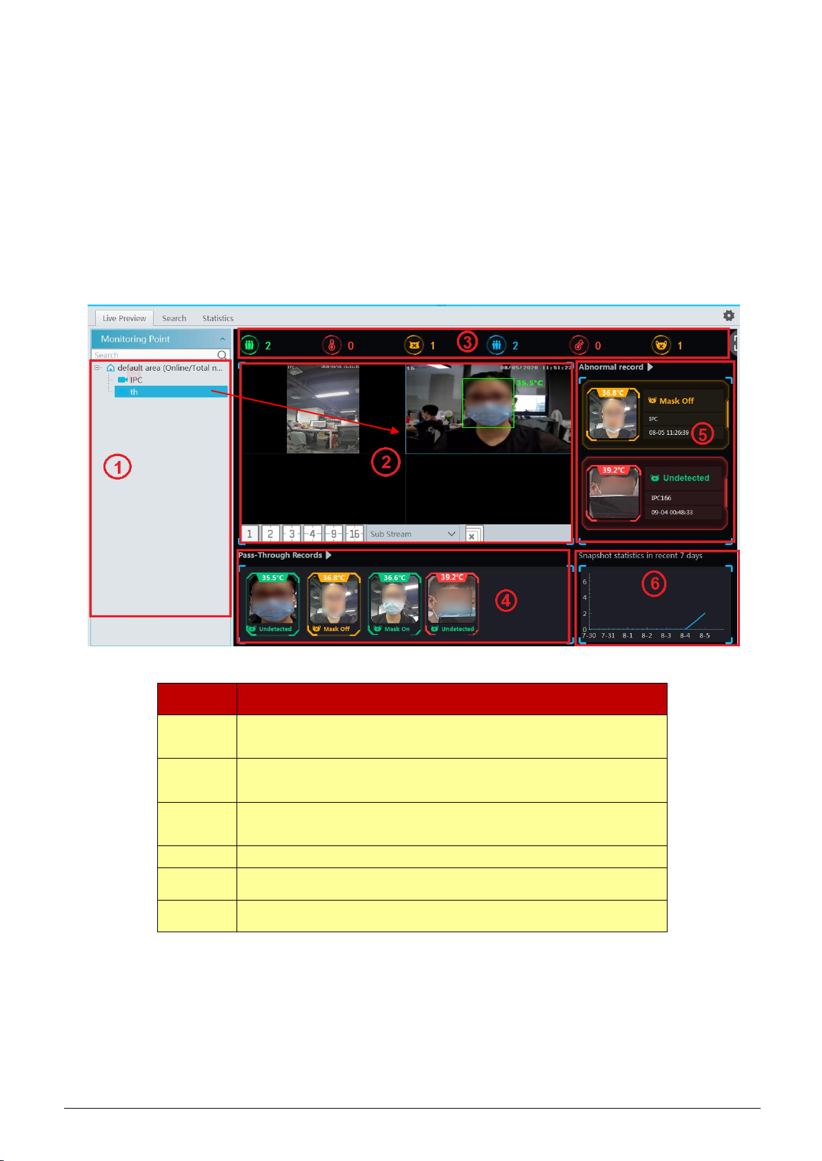
No.
Descriptions
①
Camera list, including temperature measurement terminal/panel and thermal
network camera.
②
Preview Area; drag the camera to the preview window to play.
③
Statistical display area, including such as total pass-by counts(today/total),
Over-temperature counts (today/total), mask off counts (today/total)
④
Pass-through records (snapshot display area)
⑤
Abnormal record display area, including mask off, over temp
⑥
Snapshot statistics in recent 7 days
6. Check ―Do not display normal data‖ as needed.
7. Set the data sources for temperature measurement terminal.
8. Enter the content of the abnormal voice prompt as needed. The abnormal voice prompt includes ―Over temper voice prompt‖ and
―Non-mask voice prompt‖.
6.1.2 Live Preview
Drag the thermal cameras/temperature measurement and face recognition terminals to the preview window. In this interface, you can view
various statistical information, such as total pass-by(today/total), Over-temperature(today/total), mask off (today/total), etc.
Click the captured image on area ⑤ to pop up an alarm handling box as shown below. You can edit the personal information, including
name, phone number, ID number, address, whether to go to the infected area, etc.
19
Page 24
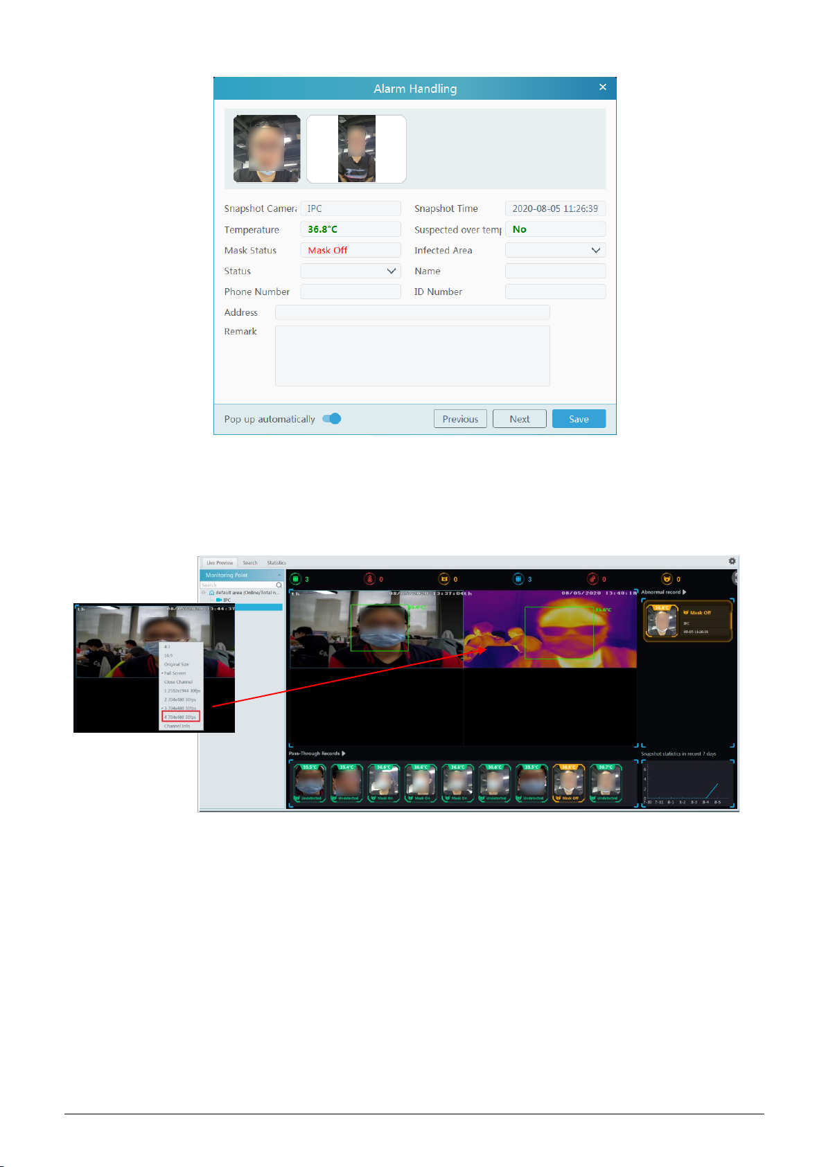
Pop up automatically: if enabled, the alarm handling box will automatically pop up on detecting an abnormal event (over temp/mask off).
The thermal image and visible light image will be displayed simultaneously if the thermal camera is dragged to the preview area. Right
click on the thermal camera window and then select the fourth stream to view the thermal image as shown below.
6.1.3 Records Search
Select the camera and then set the filter condition (like the start and end time, temperature range, keywords, etc.) to search the records.
20
Page 25
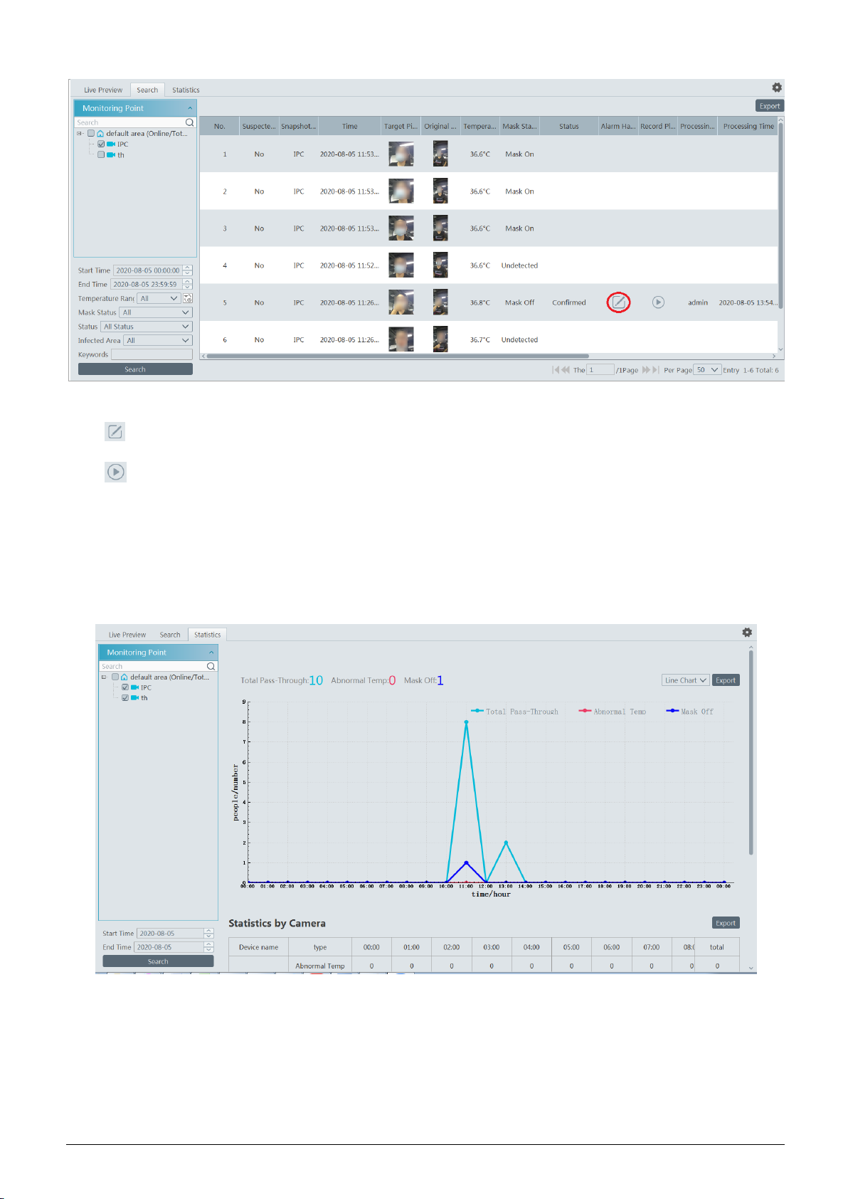
In the above interface, you can view the target picture and the original picture, body temperature, mask status, alarm handling status, etc.
Click to edit the personal information. If the alarm information has been edited, it cannot be edited again.
Click to play back the alarm record in a small window.
6.1.4 Statistics
In the statistics interface, you can view the total pass-through counts, abnormal temperature counts and mask off counts.
Choose the camera and then set the start time and end time. Click ―Search‖ to view the statistics.
You can view the statistics via a line chart or bar graph. The statistical data can be exported by clicking ―Export‖. Additionally, the
statistical information can be displayed by camera as shown below.
21
Page 26
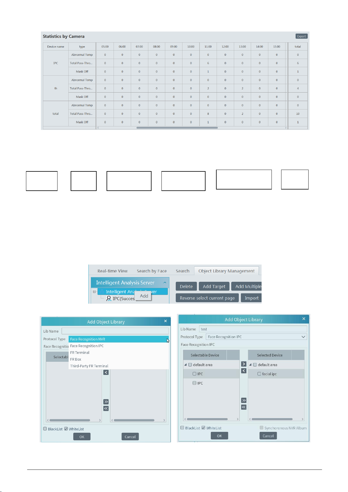
6.2 Face Surveillance
Search
faces
View face capture &
face match result
Configure face
match type
Configure face
capture type
Add
targets
Create
a library
If it is the first use of face surveillance function, please configure it in the following order.
6.2.1 Object Library
Create and edit object library by going to HomeObject Library.
Create Object Library
Right click the intelligent analysis server to select ―Add‖ to add an object library.
Object Library Name: please enter the object library name as needed.
22
Page 27
Protocol Type: face recognition IPC, face recognition NVR and FR Terminal (Face Recognition Access Control Terminal) are optional. If
face recognition IPC/NVR/terminal is selected, please select the corresponding device and click to add the device. Then this library
and its targets will be added to the face database of the added device, but the face database and its targets cannot be added to this library.
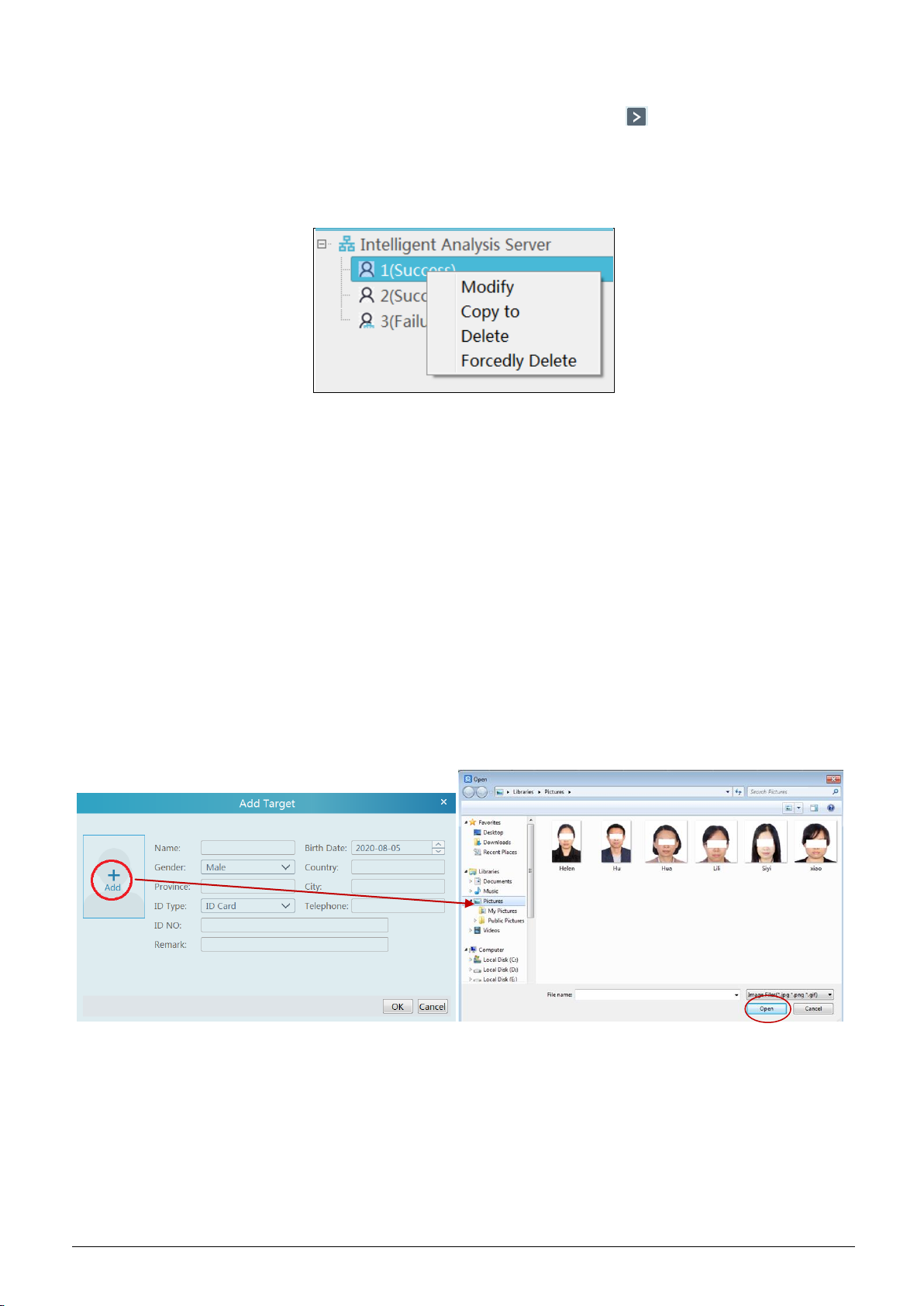
A menu box will display by right clicking the library name as shown below.
Select ―Modify‖ to modify the library name. Check ―Synchronous‖ and then you can add or delete devices. If adding a device, all targets
in this library will be copied to this device. If deleting the added device, all targets of this library will be cleared from this device.
Click ―Copy to‖ to copy the current library (A) and its targets to another library (B) and create library (B). If ―Copy to‖ face recognition
NVR/IPC/ terminal is selected, the current library (A) and its targets will be added to the face database of the above-mentioned device.
Click ―Delete‖ to delete the current library.
Forcedly Delete: This function is used to delete the library linking the face recognition NVR/IPC/terminal. When the FR
NVR/IPC/terminal is offline or disconnected with the intelligent server, you shall select ―Forcedly Delete‖ to delete the relevant library.
Add Targets
Then click this object library and click [Add Target] to create a target.
Adding multiple targets:
23
Page 28
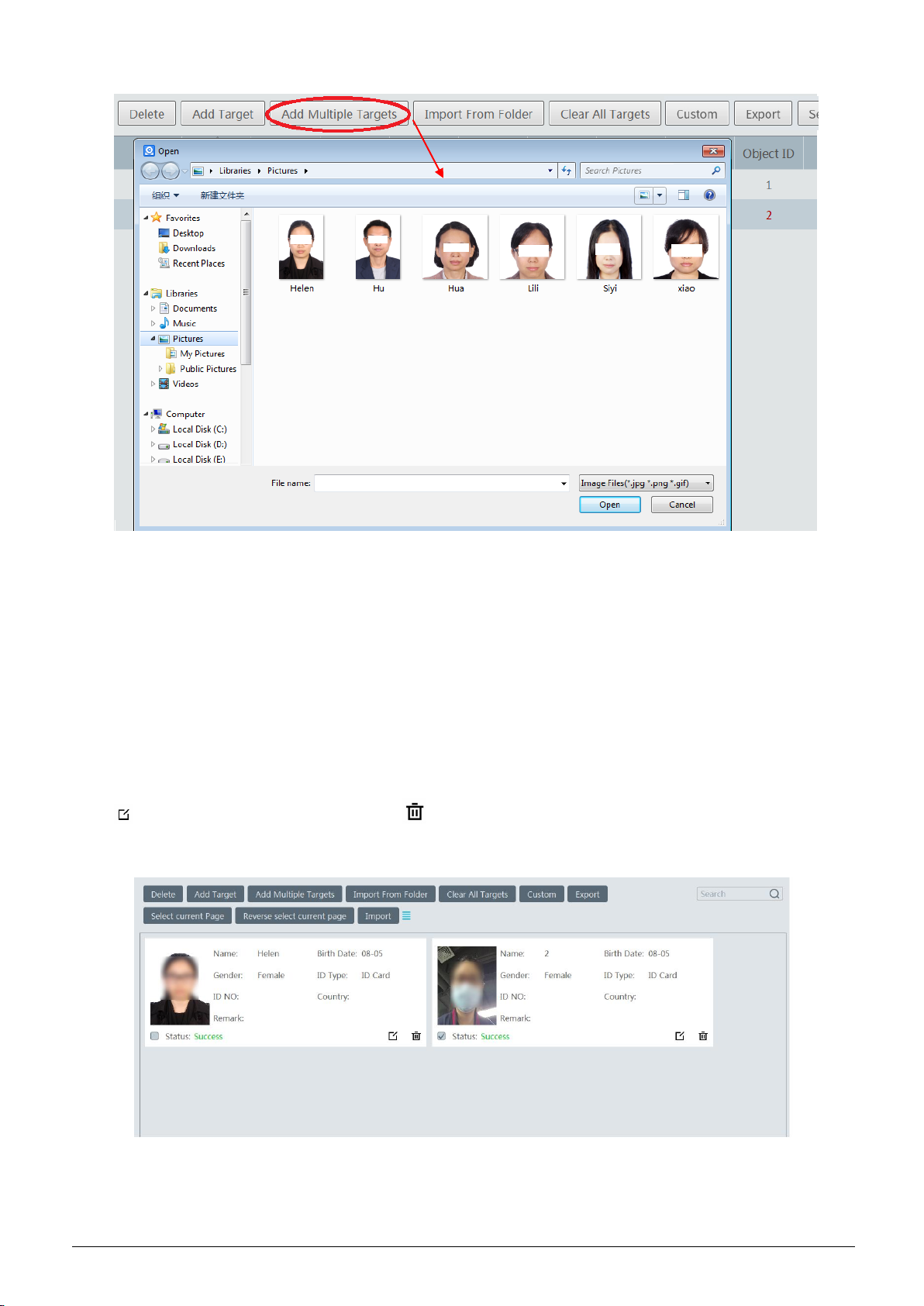
Import from folder:
Folder & Subfolders: After clicking [Import from Folder] and choosing ―Folder & Subfolders‖, choose a folder including multiple
subfolders and then all pictures in the folder and its subfolders will be imported.
Current Folder: After clicking [Import from Folder] and choosing ―Current Folder‖, choose a folder including multiple subfolders and
pictures. Then pictures in the folder will be imported, but pictures in the subfolders will not be imported.
Modify or delete targets:
Click to modify the information of the target. Click to delete the target.
Click [Custom] to customize the target information.
Import: You can add multiple targets by using this function.
24
Page 29
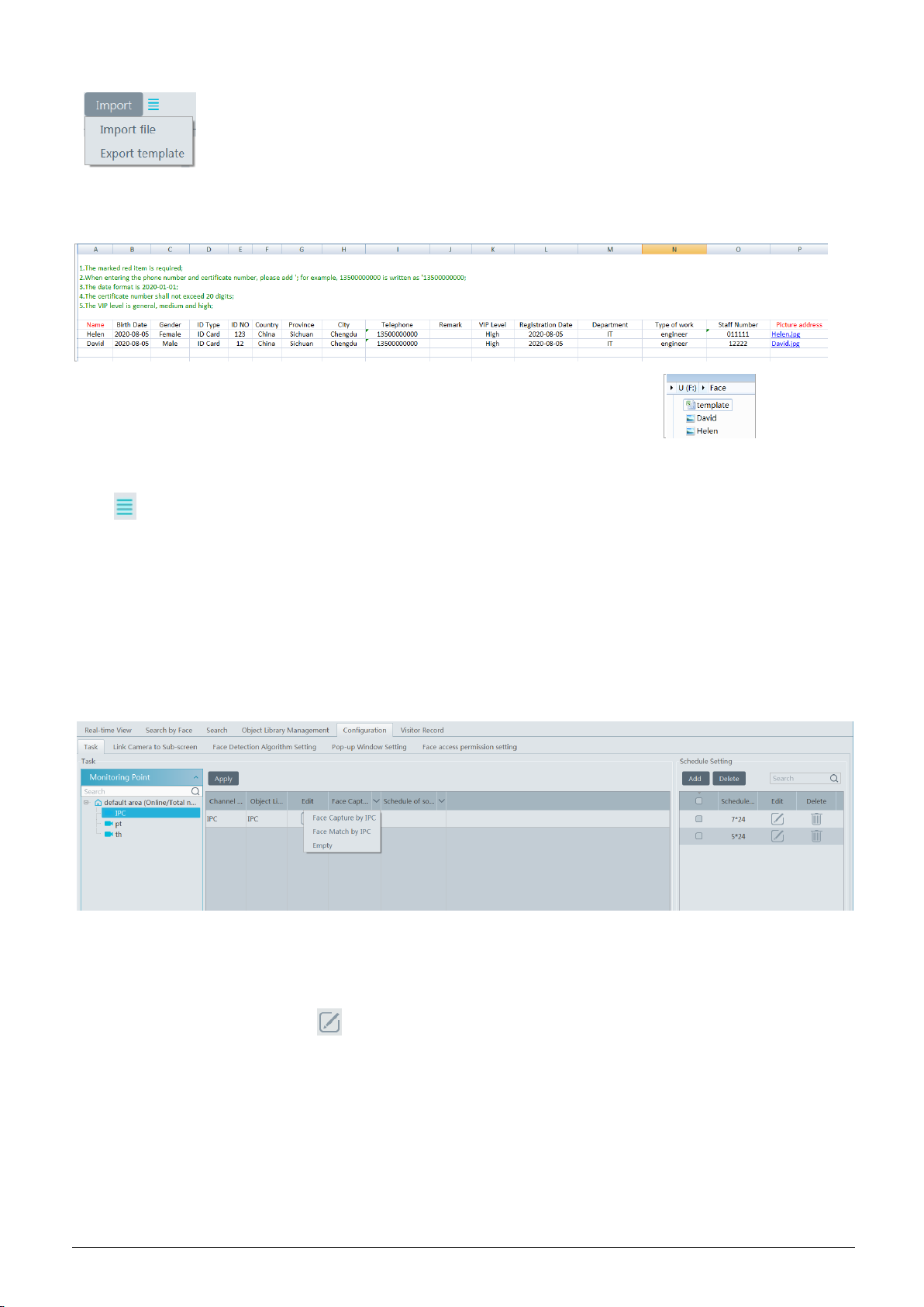
1. Click [Import] and then select ―Export template‖ to export a template. Then edit the personal information according to the tips in the
template as shown below.
2. Put the picture and the personal information file into the same directory as shown on the right picture.
3. Click [Import] and then select ―Import file‖ to select the personal information file to add multiple targets at once.
Click to view the list of the target.
6.2.2 Task Management
Go to HomeFace SurveillanceConfiguration Task.
① Select the schedule and face capture type.
There are two face capture types—face capture by IPC, face match by IPC
Face capture by IPC: if the IPC is a face detection IPC, please select it. It is selected by default.
Face match by IPC: if the IPC is a face recognition IPC, please select it.
For some face recognition terminals, the face recognition function is enabled by default, so there is no need to set the face capture type and
schedule.
② Set face match type.
Face Match by IPC: select the IPC, click and then double click the library that links the face database of IPC. Make sure this IPC
supports face match function.
25
Page 30
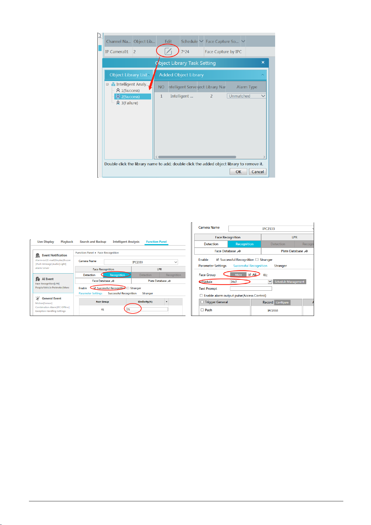
Schedule and face match configurations of NVR:
You can log in the web client of the NVR and then configure the schedule of face match, select the face group and set the similarity to
realize the auto report of the face match result as shown below.
The alarm type: Matched or Unmatched can be optional.
If ―Matched‖ is enabled, a) when the captured face picture is successfully matched, this result will be pushed to the alarm service and then
the match pictures will be shown in the Real-time View interface of Face Surveillance module; b) when the captured face picture is
unsuccessfully matched, this failure result will be pushed to the alarm service and the picture will be shown in the Real-time View
interface of Face Surveillance module too.
If ―Unmatched‖ is enabled, a) when the captured face picture is successfully matched, this result will not be pushed to the alarm service;
b) when the captured face picture is unsuccessfully matched, this failure result will be pushed to the alarm service and the picture will be
shown in the Real-time View interface of Face Surveillance module.
Note: The schedule shall be set first, or the match result will not be pushed.
6.2.3 Real-Time View
If the IPC supports face detection, you will view the face capture picture.
The screen display mode: 1/4/9/16 can be selected.
26
Page 31

If the added AI camera/panel supports temperature measurement and mask detection, you will see the detailed face match information,
including mask status, body temperature, snapshot camera, snapshot time, etc.
Click the button on the top left corner of the captured face picture to add the face picture to the library quickly; click the button
to enter the Search by Face interface quickly.
Put the cursor on the captured picture and then click to quickly search images by this picture.
27
Page 32

Put the cursor on the captured picture and then click to quickly download the captured picture.
The right panel of the real-time view interface is face match result area.
Click it to view the matched details.
Click to clear all face match result.
Click to hide the unmatched result.
6.2.4 Search
① Go to Face Recognition Search interface.
② Select the IPC and picture source.
③ Select the captured match pictures from intelligent server or face recognition NVR.
④ Set the start and end time and then click [Search] to search the face pictures.
28
Page 33

Put the cursor on the captured picture and then some shortcut buttons will be displayed.
Click + to add the capture picture to the library. Select the library on the left and then fill out the information of this target. Click [OK] to
add.
Put the cursor on the captured picture and then click to quickly search images by this picture.
Put the cursor on the captured picture and then click to quickly download the captured picture.
6.2.5 Search Image by Image
① Set the schedule and make sure all channels can be recorded normally.
② Select a picture and picture source.
③ Set the start time and the end time.
④ Set the maximum count and similarity.
⑤ Click [Search] .
Click to play the record in a small window.
29
Page 34

E-Map Track View:
① Create a E-map. You can create or delete an E-map in this interface. The hot spot can be added to the E-map too.
② Search the track
Click [Play Track Line] to play track line.
Click [Playback by Tracks] to play back records as shown below.
30
Page 35

6.2.6 Configuration
① Set the schedule.
② Face Detection Algorithm Setting
Set the similarity of face match by default and FTP as needed.
If FTP is configured, the captured face pictures will be automatically uploaded to FTP server
③ Pop-up Window Setting
31
Page 36

In this interface, you can choose whether to pop up the window when the camera detects a stranger or the person of blacklist or white list.
Additionally, you can choose the duration time of VIP Box(s).
Total Pass-by (Today)/Abnormal Temp/Mask Off/Face Match(Today)/Blacklist/Stranger: If enabled, these statistical information will be
shown on the real-time view interface.
④ Link camera to sub-screen:
If the sub-screen is connected, the system will automatically recognize it. In this interface, you can configure cameras for face attendance
and face greeting
Double click the blank area of the screen box as shown on the above left to pop up a box. Check the channel name and click to add it.
6.2.7 Face Recognition Terminal Access and Configuration
The setting steps are as follows:
1. Log in the Face Recognition Access Control Terminal (FR Terminal): If this is the first use of FR Terminal, please configure its IP
address first. Click the menu icon in the bottom right corner of FR Terminal to pop up a login box. Enter the password and click [OK].
32
Page 37

2. Modify the IP address of the FR terminal. Click SettingsEthernet SettingEthernet Ethernet IP ModeStatic to modify IP
address.
3. Create API in the web client of FR Terminal to get username and password.
Note: Only Google Chrome can be used to log in the FR Terminal. Please enter http://ip:8081 in the address bar of Chrome. The default
user name is admin and the default password is admin too.
Go to the API interface to create the ClientID and ClientSecret as shown below.
Self-define the ClientId and ClientSecret.
33
Page 38

4. Platform access:
Note: The FR terminal only can be controlled by one platform. Please do not connect one FR terminal to multiple management
platforms.
Start the monitor client and then go to the ―Add, Edit or Delete Device‖ interface. Choose ―Encoding Device‖ and then click [Add].
Click the ―Manually Add‖ tab to add a FR terminal. The protocol shall be ―FR Terminal‖.
The username must be the same with the ClientId of the FR Terminal.
The password must be the same with the ClientSecret of the FR Terminal.
Please get the ClientId and ClientSecret from the web client of the FR Terminal (See Step 3 for details).
5. Link the FR terminal to a library
(1) Add a library and create a blacklist or white list.
Go to Face Surveillance Object Library Management interface. Right click the intelligent server name and then click ―Add‖ to add a
library.
Protocol Type: please select FR Terminal.
Enter the library name and select the FR terminal. Then check blacklist or white list.
34
Page 39

(2) Add targets
Select the library linked to the FR terminal and then click [Add Target] to add targets as shown below.
(3) Go to the web client of the FR Terminal to view whether the target pictures are added successfully.
35
Page 40

(4) Face Access Permission Setting
Please enter the following interface and then click [Add User] to bind the user and face access control terminal. Drag your mouse to select
the user on the left panel and then select the face access control terminal. Click to select it. Then click [OK] to save the settings.
After that, the user will be listed in the table. Click to change the face access control terminal. Click to delete this user.
(5) Configure the schedule and library.
Click Face SurveillanceConfigurationTask to go to the Task interface as shown below. Select the FR terminal in the monitoring point
list and then click to select the object library and alarm type. Then set the schedule and face capture source.
36
Page 41

The alarm type: matched or unmatched can be optional.
If ―Matched‖ is enabled, a) when the captured face picture is successfully matched, this result will be pushed to the alarm service and then
the match pictures will be shown in the Real-time View interface of Face Surveillance module; b) when the captured face picture is
unsuccessfully matched, this failure result will be pushed to the alarm service and the picture will be shown in the Real-time View
interface of Face Surveillance module too.
If ―Unmatched‖ is enabled, a) when the captured face picture is successfully matched, this result will not be pushed to the alarm service;
b) when the captured face picture is unsuccessfully matched, this failure result will be pushed to the alarm service and the picture will be
shown in the Real-time View interface of Face Surveillance module.
If the schedule is not set, the match result will not be pushed.
(6) View the face match alarm information
After you configure the above items, you can view the alarm information in the Real-time View interface of Face Surveillance module.
You can also go to the web client of FR terminal to view the alarm information.
6.3 Face Greeting
Click ―Face Greeting‖ to go to the face greeting interface. The setting steps are as follows:
① Create an object library and add targets for this library in the VIP Management interface (See 4.2.1 Object library for details).
② Select the schedule, face capture type and face match type in the Task interface(See 4.2.2 Task Management for details).
③ Set camera deployment. Drag the camera name to the preview window. When there are targets detected, the match result will be
displayed on the right panel.
③ View the match result of the greeting screen. Go to Face SurveillanceSystemSelect projection compare channels to configure
cameras used to compare faces. In this interface, right click on the small screen to select ―Projection‖ to select face greeting screen. Then
you will see the face display on the face greeting screen as shown on the below.
37
Page 42

⑤ Search the face greeting records. Click ―VIP Search‖ tab as shown below.
You can enter the key word to search the target or manually select the target from the library. Then set the start time and the end time and
click ―Search‖ to search the record. The detailed information of this target will be viewed. Click to play the record.
⑤ Display Setting. In this interface, greeting screen background style, screen mode, VIP box style, face greeting language and so on can
be set up.
38
Page 43

Greeting Screen Background Style: three options: Video, Background Picture and Pure Color Background
Screen Mode: 1/4/9/16 screen display mode can be selected.
VIP Box Style: with borders or pure image.
Face Greeting Language: please enter the content as needed.
Max. Number of VIP Box: up to 5 boxes.
Duration Time of VIP Box: set the duration time of VIP box appearing after the captured face is matched successfully.
Loop Playback: if enabled, the VIP name will be broadcasted in a loop.
Single VIP Cycle Time: set the time of the single VIP name broadcasted.
Single VIP Box Size: set the percentage of VIP box size occupying the entire screen.
6.4 Face Attendance
Click ―Face Attendance‖ to go to the face greeting interface. The setting steps are as follows:
① Click the ―Staff Management‖ tab to create an object library and add targets for this library (See 4.2.1 Object library for details).
② Click the ―Task‖ tab to select the schedule, face capture type and face match type (See 4.2.2 Task Management for details).
③ Set camera deployment. Drag the camera name to the preview window. When there are targets detected, the match result will be
displayed on the right panel.
③ View the match result of the sub-screen. Go to Face SurveillanceSystemSelect projection compare channels to configure channels
used to compare faces. Right click on the screen to select ―Project onto‖ to select sub screen. Then you will see the face display on the sub
screen as shown on the below.
39
Page 44

⑥ View the attendance records. Select the target and search condition (by day, by week, by month, etc.) to search the records as below.
Click ―Export‖ to export the attendance record. You can open the exported record file by Microsoft Excel.
The earliest record and the latest record can be played by click the corresponding play button.
⑥ Working day settings
Please set the working day and working time as needed.
6.5 Line Crossing Counting
6.5.1 Task Management
Go to HomeLine Crossing CountingTask Management. Click to enter the following interface. Double click the camera with
the line crossing counting (or target counting) function and then select the schedule. After that, click [Apply] to save the settings.
40
Page 45

6.5.2 Real-time Statistics
Go to HomeLine Crossing CountingReal-time Statistics. Double click the camera with the target counting function to view the live
image. The camera will automatically count the number of people/motor vehicle/non-motor vehicle crossing the predefined line and the
system will automatically analyze the traffic flow trends.
Before view the statistics, please go to HomeResource ManagementDevice SettingLine Crossing Counting interface to set the alert
line, entrance/exit, detection target, etc.
Please select the type as needed to view the flow trend. Click to refresh the current statistics.
41
Page 46

6.5.3 Heat Map
Go to HomeLine Crossing CountingHeat Map interface.
Please create a map first.
42
Page 47

Drag the camera with the line crossing counting function to the specified area.
Put the cursor on the camera icon and then you will see the detailed flow statistics.
The deeper the red color is, the more targets (human/vehicle) gather there.
6.5.4 Historical Statistics
Go to HomeLine Crossing CountingHistorical Statistics. In this interface, the statistic results in a long period of time can be searched
which can be shown in the table or curve chart. Additionally, the statistics of different targets can be viewed here.
43
Page 48

6.5.5 Flow Control
Click HomeLine Crossing CountingFlow Control to enter the following interface.
Click to add a task. Multiple tasks can be added as needed.
44
Page 49

Click to modify the task.
Click to delete the current task.
Click to view the quantities of the people entry and exiting.
Click to enter the flow control preview interface.
In the above interface, you can switch the camera and view the image. When the people inside exceed the threshold, the icon will turn red.
6.6 Smart Site View
In the home page, click ―View‖ and select ―Change to Smart Site Page‖.
Face Attendance Settings
1. Click Face AttendanceTaskAttendance Settings to go to the following interface.
2. Select the area and channel.
3. Select entrance or exit.
4. Set the task for each channel. Click the ―Task‖ tab to select the schedule, face capture type and face match type (See 4.2.2 Task
45
Page 50

Management for details).
After the face attendance settings are finished, the attendance record will be shown as follows
The descriptions of the buttons on the lower left corner
:Click it to change the library.
:Click it to display full screen.
:Click it to enter the staff management interface
6.7 Smart View
In the home page, click ―View‖ and select ―Change to Smart View Page‖.
In this page, you can view the statistics of smart events, such as license plate recognition, face recognition, line crossing human/vehicle
counting. Click to enter the corresponding intelligent analysis configuration interface.
46
Page 51

7.1 Live View
NO.
Description
NO.
Description
1
Screen display mode
6
Show the smart event detection area
2
Full screen
7
Close all preview
3
Enable/disable OSD
8
Save the current view mode
4
Enable/disable broadcast
9
Choose the camera stream
5
Manual alarm output
Button
Description
Button
Description
Close image
3D zoom in
Start/stop recording
Zoom in
Go to HomeLive View interface as shown below.
7 Live View
The descriptions of the live view buttons are as follows.
Channel stream: main stream, sub stream, third stream and self-adaptive stream can be optional. When the third stream is selected, the
system will automatically switch to sub stream if the channel/camera doesn’t support the third stream.
Toolbar on the display window:
47
Page 52

Enable/disable audio
Zoom out
Snapshot
Fit to window
PTZ control
Enable/disable talkback
Monitoring point setting (camera setting)
Right-click button function:
Menu
Description
Menu
Description
Close
Channel
Close image
Snapshot
Capture images
Start Record
Start/stop recording
Start
Talkback
Enable/disable talkback
Instant
Playback
Click it to play back immediately
Channel
Info.
Display channel name, IP address and the
current stream
Audio ON
Enable/disable audio
Stream
Choose video stream
PTZ Control
Click it to show PTZ control panel
Full Screen
Display image in full screen
4:3/16:9/Original Size/Full Screen: screen display proportion; please select it as needed.
7.1.1 View Mode Setting
Users can select the common display mode and self-define the display mode through the buttons on the toolbar.
To customize the display mode
① Click on the toolbar.
② Enter screen display name and select the display row and column. Hold the left mouse button and drag on the screen and then click
[Merge] to merge the screens.
③ Click [Save] to save the settings.
④ Click [Create] to create a new display screen mode. Click [Save All] to save all customized screen display modes.
7.1.2 Monitoring Point View
Start View
To start live view, please drag cameras from the list to the right display window or select a window and then double click the camera.
The image can be dragged to any window at random.
48
Page 53

Stop View
① Place the cursor on the live view window to display the menu toolbar and then click to stop viewing.
② Right click on the live view window and then select ―Close Channel‖ to stop viewing.
③ Click on the toolbar of the live view interface to stop all live view.
7.1.3 Channel Group View
Start Channel Group View
After the channel group is set successfully (See Channel Group Setting), go to live view interface as shown below.
49
Page 54

You can start the channel group view as follows.
1. Choose the screen display mode according to the channel number of the channel group. Select a window and then double click the
channel group name or dragging the channel group to a window to play all channels in the group.
2. In the current screen display mode, select a window and then click beside the channel group name to play all channels of the
channel group in this window in sequence.
Stop Channel Group View
① Place the cursor on the auto-switch window and then click to stop viewing.
② Right click the auto-switch window and then click ―Close Channel‖ to stop viewing.
③ Click on the toolbar of the live view interface to stop all live view.
7.1.4 Plan View
In the live view interface, select ―View‖ on the left menu bar.
Add View Plan:
50
Page 55

① Right click ―Live View 1‖ and then select ―Create View‖ or click to add a new view plan. Clicking ―Create View‖ to prompt an
adding view window. Enter the view name and click [OK] to set view plan.
② Select screen display mode and then drag monitoring points or channel group to each window.
③ Click ―View‖ on the left menu and then right click the newly added view name. Select ―Save View‖ on the pop-up menu to save the
view plan or click on the live view interface to save the view plan.
Double click view name to call the view plan.
Modify or Delete View Plan
Select the added view and then right click to prompt a pop-up window. Select ―Modify View‖ or ―Delete View‖ to modify or delete the
view plan.
7.2 View Control
Multi-screen Display
In the live view interface, the screen display mode can be selected as shown below.
Full Screen Display
In the live view interface, click button on the toolbar or right click on the mouse to select ―Full Screen‖ to display the window in full
screen mode. Right click on the mouse to select ―Exit Full Screen‖ on the full screen interface to exit full screen.
Single Channel Display
Double click a window to view in single channel mode. Double click the window again to recover the window.
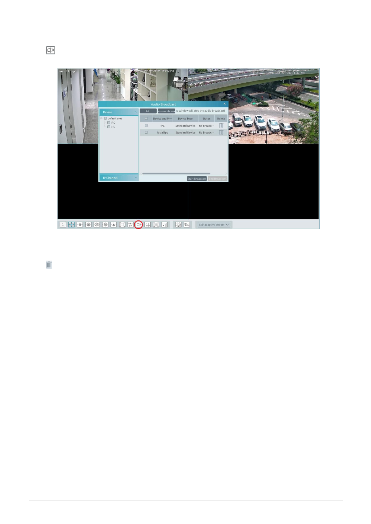
Audio Broadcast
Click to bring audio broadcast box as shown below.
The left device list shows the devices that support audio broadcast. Check the device and click [Add] to add the desired broadcast device.
Click [Start Broadcast] and then all added device will start broadcast. Select the added device and click [Delete] to delete the device.
Stream Setting
Right click on the live view window to choose video stream. Or select self-adaptive stream or other stream on the toolbar to set the stream
for all channels.
To set streams
Go to Home Device Setting. Select the device and click ―Stream Setting‖ tab to set streams.
Audio Control
Right click on the live view window and then choose ―Audio On‖ or click on the toolbar of the window to enable audio.
Note: Only one audio can be enabled at the same time. If the audio of one channel is enabled, the former audio will be disabled
automatically.
Zoom In or Out
51
Page 56

In the live view interface, click on the live view window to zoom in the window and then drag the image to view the whole image;
click to zoom out the image; click to restore the image size.
7.3 Snapshot
Select a window in which the video is playing and then click on the toolbar of this window or right click on the window and then
select ―Snapshot‖. The image number and storage path will be displayed.
Note: Only when the video is playing in the window, will the snapshot succeed.
The snapshot will be saved in the Mini CMS Server by default. A maximum of 100 snapshots can be saved. If more than 100 pictures are
captured, some previous snapshots will be overwritten.
7.4 Multi-Screen View
In the live view interface, multi-screen view can be realized by holding a tab and dragging it to other monitors (graphics card should
support multi-screen output at the same time).
52
Page 57

Click on the float window and select ―Return to Main Window‖ to embed this tab in the main interface.
7.5 Talkback
In a live view window, click on the toolbar of this window or select ―Start Talkback‖ on the pop-up menu by right clicking to enable
talkback.
Note: Since the software only allows enabling one device’s talk at the same time, the system will stop talking with the current device if a
new talk is enabled.
7.6 PTZ Control
Click or right click to select ―PTZ Control‖ to enter PTZ control interface. The directions of PTZ, zoom, focus, Iris, preset,
track and cruise can be controlled through PTZ control panel.
53
Page 58
7.7 Audio Broadcast
Click to pop up an ―Audio Broadcast‖ interface as shown below.
Check the left device and then click ―Add‖ to add the device you want to broadcast.
Check the added camera on the right and then click ―Start Broadcast‖.
Click to delete the added device.
Choose multiple devices and then click ―Remove‖ to delete them at a time.
54
Page 59

8 Record & Playback
8.1 Record Configuration
This device supports many recording types, such as manual recording, schedule recording, motion alarm recording, smart alarm recording,
etc.
8.1.1 Manual Recording
In the live view interface, select a channel and then click or right click to select ―Start record‖ to start recording. Click this button
again to stop recording.
Note: If a channel is recording, the recording will stop when the viewing window is closed.
8.1.2 Schedule Recording
Go to Home―Record Setting‖.
To set schedule recording, select the channel, stream type and schedule. Then Click [Apply] to save the settings.
To set schedule:
① Click the ―Schedule Setting‖ tab to go to the following interface.
② Click [Add].
③ Enter the schedule name.
④ Set the schedule. Click and then move the cursor to select the time; click and then move the cursor to delete the selected
time. Click ―Input Manually‖ to manually enter the time. Click ―All‖ or ―Reverse‖ to quickly select time. Click ―Clear All‖ to clear
all schedule.
55
Page 60

8.1.3 Alarm Linkage Recording
① Go to Home Device Setting interface. Select the desired device to enable and set schedules.
② Go to HomeAlarm CenterAlarm Linkage as shown below. Select alarm type, enable record, set linakage channel and set
schedules.
③ Click [Apply] to save the settings.
8.2 Record Playback
In the main menu interface, click ―Record Playback‖ to go to record playback interface. Record files saved on the HDD/ SD card of the
devices and storage server can be played.
There are two types of record playback: synchronous playback and asynchronous playback.
56
Page 61

Area Description
Area
Description
Area
Description
1
Playback area
3
Record timetable area
2
Toolbar
4
Time and event search area; resource area
Button
Description
Button
Description
Stop viewing
Zoom in
Audio on/off
Zoom out
Snapshot
Fit to window
Button
Description
Screen display mode button. 1/4/9/16 screen mode is optional.
Full screen
Enable or disable OSD
Close all window viewing
Get record from network devices
Get record from storage servers
Rewind
Low speed playback
Stop
Toolbar on Playback Window
Button Descriptions of Area 2:
57
Page 62

Play/Pause
Next frame. In the playback mode, click the pause button and then click this button to play
frame by frame.
Click it to select playback speed.
Forward 30s or backward 30s
Backup start time
Backup end time
Start backup
Synchronous playback or asynchronous playback
Right-click button menu
Menu
Description
Menu
Description
Close
Close viewing
Zoom out
Zoom out the current image
Audio
On/Off
Audio on/off
Full Screen
Click to enter full screen mode
Snapshot
Snapshot
Sub stream
Switch to sub stream playing
Zoom In
Zoom in the current image
Button
Description
Button
Description
Add tag
Event list
Backup
Other buttons
Set record date, record type (for some devices, ―Main Stream‖ can be selected to play the record, or the record will be played by sub
stream if unselected) and the record playback source in the playback interface. Drag the camera on the right side to playback window for
playing or double click a desired channel to play or click [Search] to search the record files and then click to play.
Playback record type includes manual recording, motion detection recording, schedule recording, sensor recording, object removal
recording, video exception recording, intrusion recording and line crossing recording and so on.
In the timetable, different color bars stand for different record types. For instance, yellow bar stands for motion recording data; blue bar
stands for schedule recording data; red bar stands for sensor record data, etc.
The time scale can be zoomed in by clicking and the time scale can be zoomed out by clicking . The time scale can be restored
to 24 hours by clicking . When the time scale is zoomed in, drag the timeline to see the time spots.
8.2.1 Instant Playback
Instant Playback
In the live view interface, right clik on a playing channel to select ―Instant Playback‖ and then set the playback time to play the record
instantly (the record of the channel in the past five minutes will be searched and played from that time when the record exists).
58
Page 63

8.2.2 Synchronous Playback
Synchronous Playback: in a certain time, all channels play back its record at the same time together; if one channel has no record data at
this time, this channel will wait.
Click on the toolbar in the playback interface to go to the synchronous playback interface. Please play the record according to the
ways introduced as above. The record bar in synchronous mode is as below.
In synchronous mode, one camera can only have one playing window. All cameras’ record information can be viewed at the same time.
When playing record file in synchronous mode or asynchronous mode, clicking or will be useless unless all the playback
windows are closed.
8.2.3 Asynchronous Playback
Asynchronous Playback: when playing some channels’ record at the same time, each channel is independent from the others and each
channel’s playback time is different.
Click to go to the asynchronous playback interface as shown below. Please play the record according to the ways introduced as the
above. The record bar in asynchronous mode is as below.
8.2.4 Playback by Time Slice
① Go to HomeBy Time Slice interface.
② Select channel (or monitoring point), set the start time and the end time, select the record source and then click [Search].
59
Page 64

③ Click to play the record.
Click button on the top right corner to play in full screen mode.
Double click the image to switch to slice search mode by day. In the above interface, click to switch to slice search mode by hour.
60
Page 65

CMS User
Double click an image to switch to slice search mode by 5 minutes. Click
In the above interface, click to return to slice search mode by hour.
Backup: In the Search by Time Slice interface, select a time slice and then click ―Backup‖ to back up the record file during this period
quickly.
to return to slice search mode by day;
8.2.5 Playback by Event
① Go to Home By Event interface.
② Select the desired monitoring point, set the record source, the start time and the end time and then check events.
③ Click [Search]. The searched record data will be listed. Click to play the record; click to back up the record data.
8.2.6 Playback by Tag
① Go to HomeRecord Playback interface.
② Select a channel and put the cursor on the right center. Then a tag icon ( ) will appear. Click this icon to add tag.
③ Go to HomeBy Tag interface. Select the start time and click [Refresh] to search the added tags.
④ Click in the playback column to play the record.
61
Page 66

8.3 Backup
In the main menu interface, click ―Backup‖ to go to the backup interface. The setting steps are as follows:
① Select the desired monitoring point.
② Select date and click ―More‖ to select the start and the end time and event type.
③ Click / to get records from device or storage server.
④ Set the start time and the end time of backup. Then click [Backup].
⑤ The backup progress will be seen during backing up the record. Click to pause; click to stop backing up the record; click
to clear the backup list.
―Backup on device‖: This function is applied to the added NVR devices. Search the record from the HDD of the NVR in this interface and
then insert a USB storage device into the USB port of the NVR and then click this button. Then the recorded files will be backed up to the
USB storage device remotely.
8.4 Search Picture
In this interface, pictures stored on the SD card or storage server can be searched and viewed.
62
Page 67

① Select the device.
② Set the start time and the end time.
③ Choose events.
④ Click [Search]
63
Page 68

9 Alarm Management
9.1 Alarm Server Configuration
Alarm server is in charge of receiving and recording alarm information of connected devices and then sending the alarm information to the
relevant user terminal system or devices in accordance with prior alarm settings. There is a default alarm server.
Go to HomeAdd, Edit or Delete Device Alarm Server interface to view the online status of the alarm server. If it is not online, please
check its network connection.
Click to modify the added alarm server; click to delete the added alarm server.
9.2 Alarm Configuration
① Go to HomeDevice Setting interface.
Select the desired device to enable alarms (refer to the user manual of the corresponding device for the detailed settings).
② Go to HomeAlarm CenterAlarm Linkage interface.
Select area, alarm type and then enable alarm linkages.
All ON: enable all alarm linkages of the current alarm type and area (schedule excluded).
All OFF: disable all alarm linkages of the current alarm type and area (schedule excluded).
64
Page 69

CMS User
Select
Select beside the title (like record) to enable record linkage of all devices (schedule excluded).
The alarm linkage settings of PTZ control, record, alarm view, snapshot, alarm output and TV Wall are the same with each other. Here take
record linkage for example to introduce the setting steps.
beside the device name and select ―ON‖ to enable all alarm linkages of the device (schedule excluded).
Check the selectable channel and click to select the channel; check the selected channel and click to remove this channel; click
to select all channels; click to remove all selected channel.
After the channels are selected, check ―On‖ and then click ―OK‖ to save the settings.
③ Set alarm schedule. Select the schedule of the desired device. 7*24 or 5*24 is the default schedule. Other schedules need to be set in
advance. Click the ―Schedule Setting‖ tab to set (See Schedule RecordingTo set schedule for details).
Manual Alarm Out:
Click ―Manual Alarm Out‖ tab to go to the following interface.
Select the camera and then click [Trigger Alarm Out] to manually trigger the alarm out of the camera; click [Close Alarm Out] to manually
turn off the alarm out of the camera.
9.3 SOP Settings
Click the ―SOP Setting‖ tab in the alarm center interface to go to the following interface as shown below.
1. Click ―+‖ to add a SOP name. A maximum of 10 SOP can be added.
2. Click ―Create‖ to create a SOP action. Each SOP can create 5 SOP actions.
3. Click to extend the alarm list.
4. Click to handle the alarm. Select the SOP action and then click ―Save Process‖. After that, choose disposition and enter remark
as needed.
The disposition includes: False alarm, true alarm, customer test, technical event, service test.
65
Page 70

After the alarm is processed, the alarm handling status and disposition will be shown as below.
If you create more than one SOP, you can designate the SOP for the added encoding devices. Go to HomeResource ManagementAdd,
Edit or Delete DeviceEncoding Device interface. Then click [Select SOP] to select the SOP and encoding devices.
Select the SOP. Then check the desired device and click to select it. Finally, click [OK] to save the settings.
After that, you can choose the corresponding SOP action when you handle the alarm of the camera.
9.4 Alarm View
Having set the alarm preview linkage, the alarm view window will prompt when an alarm is triggered.
66
Page 71

Click on the bottom right corner to expand the alarm list as shown above. Hover the mouse over the top of the alarm list and then a
bidirectional arrow will appear. Drag the alarm list up or down to zoom in or out the alarm list.
Click or to play the record or captured images; click to delete alarm information.
9.5 Alarm Log
Alarm logs can be searched and exported by going to HomeAlarm CenterAlarm Log interface.
67
Page 72

Click to play the record; click to open the snapshot search window as shown below.
68
Page 73

10 E-Map
The e-map service is used to store the e-map information of the system. The client landing anywhere can share the same e-map.
10.1 E-Map Settings
10.1.1 Create E-Map
Go to HomeE-Map Setting interface. Click [Create Map] to create a map.
Enter E-map name, select parent e-map and map type. Then click [OK] to save the settings.
10.1.2 Add Hotspot
The hotspots include monitoring points and sensors. Drag a hotspot to the corresponding area on the map as shown below.
Click [Modify Map] to change map name and parent map.
Select [Delete Map] to delete the added map.
10.1.3 E-Map Monitoring
Go to HomeE-Map Monitoring interface. Select a window on the right and then double click the monitoring point to view the real-time
image.
69
Page 74

Alarm view: if you select ―Yes‖, the monitoring video will automatically pop up on the right window when an alarm is triggered.
70
Page 75

11 TV Wall
11.1 Add TV Wall Server
Go to Home Add, Edit or Delete DeviceTV Wall Server interface as shown below.
An adding TV Wall window will be prompted by clicking [Add]. Click [Refresh] to quickly add the TV wall server in the same local
network, or add the TV wall server by manually entering server name, IP address and port.
Click to modify the added server; click to delete the added server.
11.2 Add Decoder
Decoder is used to decode the video signal transmitted by the transfer server. The decoding output is a standard video signal. The decoder
is necessary for decoding videos on the TV wall.
Go to HomeAdd, Edit or Delete DeviceDecoder interface.
The setting steps of adding decoders are the same as adding encoding device setup (see Add Encoding Device for details).
11.2.1 Create and Connect Decoder
The decoder which needs to be connected to the platform must be the master decoder and in platform mode. Login the web client of the
decoder as shown below.
Go to Basic Settings System Settings to check the user permission and running mode of the decoder and make sure its user permission is
master and its running mode is platform. Then apply the settings and restart the decoder.
After that, go to HomeTV Wall ManagementTV Wall System SettingDecoder Bind Configuration. Then click to bind
71
Page 76

decoder and TV wall (See Decoder Bind for details).
11.3 TV Wall Management
Go to HomeTV Wall Management TV Wall Setting.
11.3.1 TV Wall Settings
Create TV Wall
Go to HomeTV Wall ManagementEdit TV Wall. Select a TV wall server and then click to create a TV wall.
Initializing
① Double click the created TV wall to prompt a TV wall window.
② Click ―Initialize‖ to create TV wall layout
72
Page 77
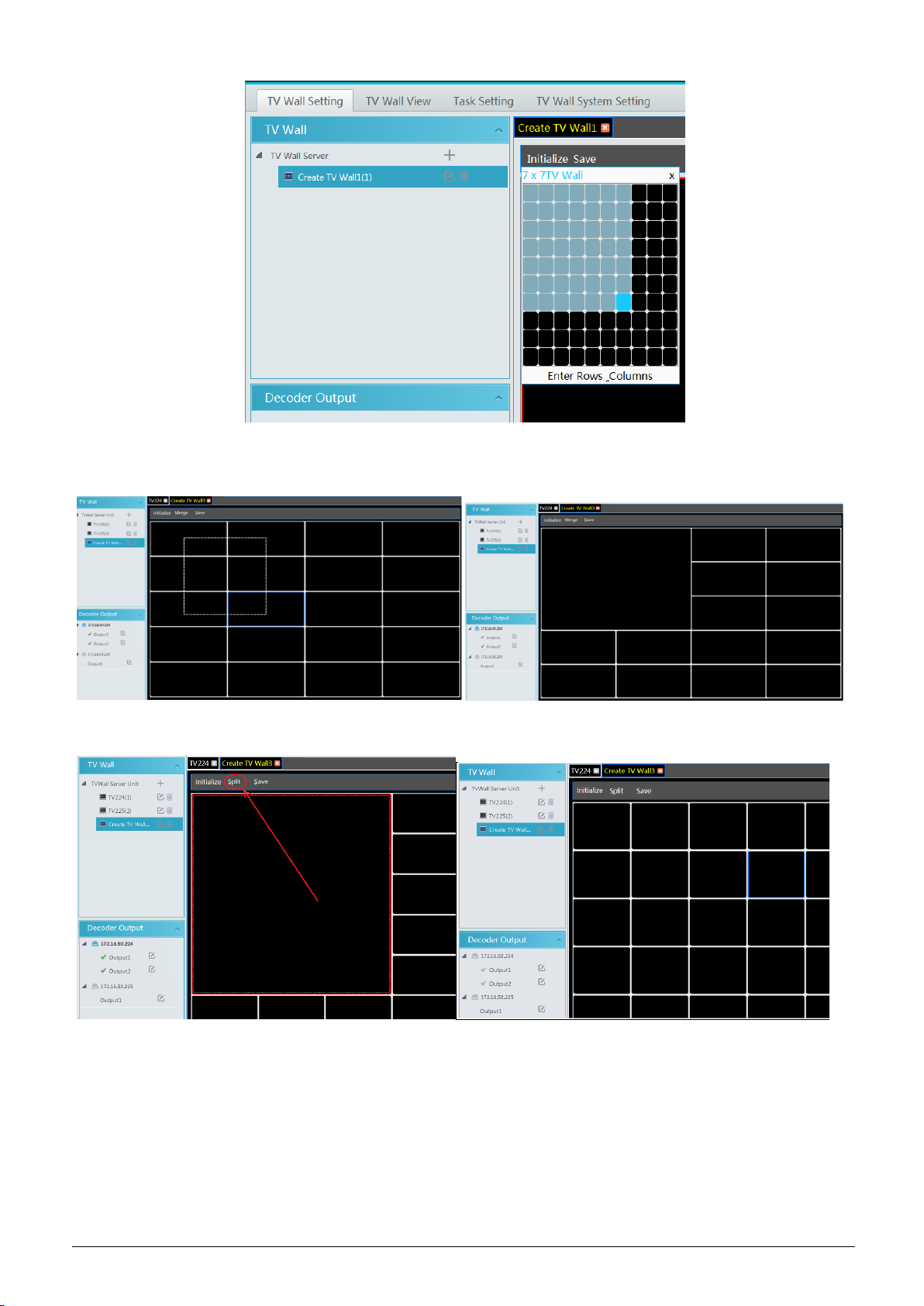
Merging\Splitting
Merging: drag on the screen and then release. The ―Merge‖ button will be shown. Click it to merger these small windows.
Splitting: select the merged window and click ―Split‖ to restore the window to the previous status.
The online decoder displayed in the decoder output list is the binding decoder of this TV wall. Drag the outputs to windows on the right in
sequence and then click ―Save‖ to save the settings.
73
Page 78

To modify TV wall:
Click beside the TV wall name, enter the new name and then click [OK].
To delete TV wall:
Click behind the TV wall name.
Decoder Bind
Go to HomeTV Wall ManagementTV Wall System Setting interface as shown below. In this interface, decoder bind can be set up.
Decoder bind configuration: modify the binding state between decoder and TV wall.
74
Page 79

Click to change bound TV Wall.
Return to the decoder management interface as shown above. The online status of the decoder indicates that the decoder is successfully
bound with TV wall. Go to TV Wall Setting interface as shown below. Drag the outputs of the decoder to the window on the right and save
them to complete output bind.
75
Page 80

11.3.2 TV Wall View
Create Plan
Go to Home TV Wall Management TV Wall ViewTV Wall Plan.
Click beside the TV wall name to create the TV wall plan name.
Configure Plan
Double click the plan name to show the plan.
Drag the monitoring points to the corresponding window respectively to decode image.
76
Page 81

Toolbar Menu
1. Screen mode:1\4\9\16\25\36 screen mode is optional.
2. Open Window:Click [Enable PIP] and then drag on a window to open a small window on it. Click [Disable PIP] to stop
opening window. The small window can be dragged to anywhere on the big window.
3. Click [Hide ID] to hide the window number; click [Display ID] to display the window number.
4. Click [Save] to save the current plan.
5. Click [Save as] to save it as another plan.
Double click a window to play the video.
77
Page 82

Right-click Menu
1. Screen mode:1\4\9\16\25\36 screen mode is optional.
2. Zoom in\out:if the current screen mode is multi-screen display mode, click ―Zoom In‖ to zoom in the current image. Click
―Zoom Out‖ menu again to restore to the previous status.
3. Save as Alarm Window: click it to save the current window as an alarm window. The alarm linkage image will be displayed in
this window. Go to Home Alarm CenterAlarm Linkage (or HomeAlarm SystemAlarm Linkage) interface. Select TV
wall linkage item to set alarm linkage.
4. Set as Playback Window:when decoding images, click this menu to play the records of the current channel (the record source
78
Page 83

is the current record source).
5. PTZ Control: click this menu to prompt a PTZ control panel of the current decoding window. Direction control, zooming and
focusing, Iris control, speed, preset, track and cruise calling can be operated through this control panel.
6. Stop Decoding: click it to stop decoding the current image.
7. View Decoder: view the information of the decoder.
8. Clear TV Wall: click it to clear the decoding configuration of the current output.
Screen Merging or Splitting
Drag the mouse to select multi-window and then click [Merge] to merge these windows.
Select the merged window and click [Split] to restore the window to its previous status.
Auto-Switch Group
1. Create Auto-Switch Group
① Click Auto-Switch Group under the screen and then click to create auto-switch group.
79
Page 84

② Select ―Auto-Switch Window‖ to select the window group.
③ Click ―Monitoring Point‖ to select the auto-switch channel group.
④ Enter auto-switch name and dwell time.
2. Execute auto-switch
80
Page 85

Click to execute auto-switch. The specified channel images will be played in the specified windows in sequence.
Click to stop playing the current auto-switch.
3. Modify or delete auto-switch
Right click the auto-switch name and then select Modify or Delete to modify or delete the auto-switch.
Note: If there are overlapped auto-switch window in a plan, the auto-switch groups will not be executed at the same time.
Auto-switch plan
1. Create auto-switch plan
Click behind the TV wall plan name to set the auto-switch. Click ―Join in‖ to select the plan. Then set dwell time and click
[OK].
2. Start/stop auto-switch
Click behind the TV wall name to start auto-switch plan. Click the Stop button to stop the auto-switch.
3. Modify auto-switch plan
Click again to modify the auto-switch plan.
Note: If the current auto-switch plan needs to modify, please stop it first.
11.3.3 Decoder Input
Go to HomeTV Wall ManagementDecoding on TV WallDecoder Input. Drag an input to a window to execute decoding.
81
Page 86

11.3.4 Playback
Playback on TV Wall
Click ―Preview‖ on the left panel. Then this button becomes ―Playback‖. Click / to get records from device or storage server
and then click ―OK‖ to search records, or drag the cameras (or channels) to a window to search and play the records.
Of course, the specified time and event types can be set to search the specified records.
Playing control
During playback, the record can be controlled by the above buttons.
Right-click menu
82
Page 87

1. Screen mode:1\4\9\16\25\36 screen mode is optional
2. Zoom in
3. Save as an alarm window
4. Save as preview window::the current channel or the historical channel is optional.
5. Playback stream type: main stream or sub stream is selectable.
6. Stop decoding
7. View decoder information
8. Clear TV wall
The following picture is an example of TV Wall.
11.3.5 Task Setting of TV Wall
Go to HomeTV Wall ManagementTask Setting. Click behind the TV wall name.
Select plan name, enter task name, set run time and enable plan task.
Click to start the task. Click the Stop button to stop this task.
83
Page 88

Modify or delete task
Double click the TV wall name and then the tasks will be displayed on the right window.
Click or to modify or delete the task.
Click behind the TV wall name and then click [OK] to confirm the deletion.
11.3.6 TV Wall System Configuration
Go to HomeTV Wall ManagementTV Wall System Setting interface as shown below. In this interface, the channel number can be set
up.
Channel number configuration: set the channel number and make the channel convenient to be controlled by the network keyboard
controller. Users can export these channel number in this interface.
84
Page 89

85
Page 90

12 Account and Permission
12.1 Create Account
Go to HomeAccount and Permission.
There is a default super admin user (the username is admin; the password is 123456). The super admin user cannot be deleted.
Click [Add] to prompt an adding user window as shown below.
Enter user name and password. Then select permission group (it must be set in advance). Binding MAC address or remark can be filled in
as needed. After that, click [OK] to save.
Click to modify the added user; click to delete the added user.
12.2 User Permission Settings
Go to HomeAccount and Permission User Permission Group Setting.
① Click [Add] to create permission group.
86
Page 91

② Enter permission group name.
③ Select system permission, operation permission, area permission and TV wall permission as needed.
Click to modify the permission group; click to delete the permission group.
87
Page 92

13 Operation and Maintenance Management
13.1 Check and Export Log
Go to HomeOperation and Maintenance Management.
Click the ―Check and Export Log‖ tab as shown below. All types of logs can be searhed and exported here.
Select the log type, set the start time and the end time and then click [Search] to search logs. After the logs are searched, click [Export] to
export these logs.
13.2 Backup and Restore Configuration
Go to HomeOperation and Maintenance Management. Click ―Backup and Restore Configuration‖ to go to the following interface.
You can import the former system configuration files to the new version. Click [Backup System Configuration] in the last version to
backup the system configuration files. Then click [Restore System Configuration] in the new version to restore the system configuration.
13.3 Viewing Online Status
Go to HomeOperation and Maintenance ManagementOnline Status interface.
You can view the online status of encoding device, decoders and storage servers and the record status of the storage server and encoding
devices.
88
Page 93

13.4 Viewing Status Log
Go to HomeOperation and Maintenance Management Status Log interface.
In this interface, record status, online or offline status of servers and monitor client can be viewed.
Set the start time and the end time and then click [Search] to search status logs.
89
Page 94

14 Local Configuration
14.1 Record and Snapshot Settings
Go to HomeLocal Configuration.
In this interface, the storage path of recording files, backup files and snapshots, backup file format, snapshot number and max file size for
manual recording and record backup can be set up here.
14.2 Local Settings
Go to HomeLocal ConfigurationLocal Setting.
Auto Startup: if enabled, the system will automatically start when the computer starts.
Auto Login: if enabled the system will automatically log in when running this software next time.
Auto Startup: if enabled, the system will automatically start when the computer starts.
Show tips when the node is offline: if enabled, the system will pop up tips when there is node offline.
Trigger audio when the node is offline: if enabled, the system will trigger audio when there is node offline.
Full name display for DVR/NVR’s channels: if enabled, the DVR/NVR’s channel name listed in the resource tree will show the
DVR/NVR name and the channel name. If disabled, only the channel name is shown.
Verify the password before exiting the program: if enabled, you shall enter the password before exiting the program.
In this interface, you also can select the resource tree sorting rules, video configuration rules, language and upload various alarm audio
files. You can click [Synchronize platform time] to synchronize the time of all devices and the platform.
90
Page 95

14.3 Overload Settings
This system supports CPU and memory overload protection. When the system overloads, the monitor client will restrict the new live view
and playback operation and the overload tip will prompt. Go to HomeLocal ConfigurationOverload Setting. Select the overload upper
limit and then click [Apply] to save the settings.
14.4 Alarm View Settings
Go to HomeLocal ConfigurationAlarm View Setting.
In this interface, users can enable ―Automatic Pop-up Alarm Page‖ or ―Full Screen Display when Popping up‖, set ―automatically
/manually close alarm page‖ and select the number of screens (1/4/6/19 optional).
14.5 OSD Position Configuration
Click HomeLocal ConfigurationOSD Position Config to go to the following interface.
Drag the slider to the position you want to show the OSD and then click ―Apply‖ to save the settings.
14.6 System Configuration
Click HomeLocal ConfigurationSystem Config to go to the following interface.
91
Page 96

In this interface, you can enable ―Alarm preview using third stream‖ or ―Do not display the alarm without schedule‖.
Enable and set the same alarm reporting interval and its linked alarm type.
Choose ―Synchronize devices‖ and ―Synchronize Time Zone‖ and then click [Synchronize Platform Time] to synchronize the device times
with the time of the platform.
14.7 Audio Uploading
Go to HomeLocal ConfigurationAudio Uploading.
Click [Add] to bring the following box.
Click [Browse] to choose the audio file and then enter the audio name. Click [OK] to save this audio. After the audio is uploaded
successfully, you can listen to it.
92
Page 97

15 Parking Lot Management
Before using parking lot management module, please add ANPR cameras first in the resource management interface.
15.1 System Settings
① Enable the parking lot. Go to HomeParking Lot ManagementSystem menu as shown below. Select Entrances Config tab and then
click the main park. Enable this main parking lot, its sub parking lot and gateway and lane.
② Bind the ANPR cameras. Please bind the ANPR cameras to the activated lane. Choose the ANPR camera and then click to add it.
Click [Apply] to bind this camera to the lane. Choose the ANPR camera and then click to unbind it.
Set the corresponding lane of the monitoring window. Then click [Apply] to save the settings. After that, you can go to the vehicle
monitoring interface to view the live images of the left and right lane.
③ Bind LED Screen. Choose the LED screen and then click to add it. Click [Apply] to bind this LED screen. Before binding
the LED screen, please go to HomeResource ManagementLED Display Device interface to add LED screen. In the following
interface, click [Add] and then enter the IP address port of the LED display screen. Click [OK] to save the settings.
93
Page 98
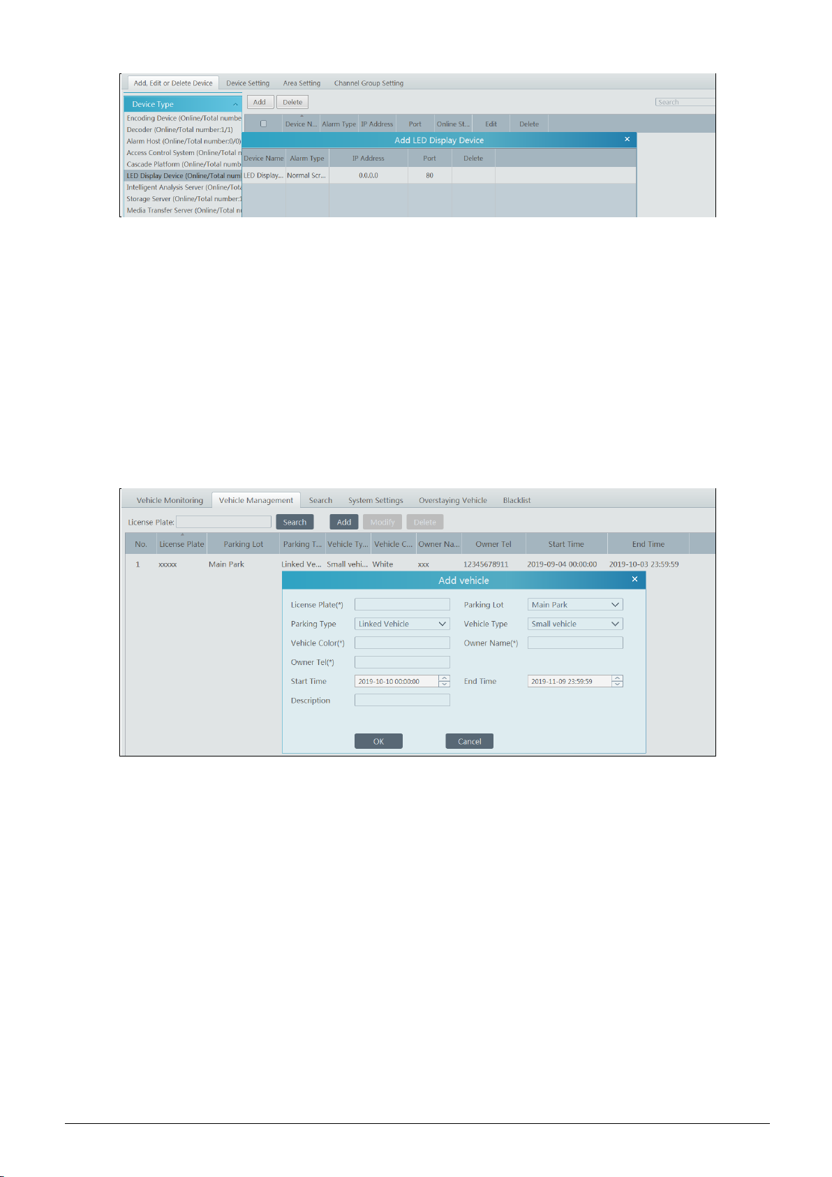
After the LED screen is bound to the corresponding lane, the license plate number will be displayed on this LED screen when there is a
vehicle passing.
④ Set the delay time of closing the gate barrier. For example, it is set to 15s. Then the gate barrier will be automatically closed after it is
opened for 15s. If ―Temporary Vehicle‖ is checked, the gate barrier will be automatically opened when temporary vehicles and
non-blacklist vehicles pass the ANPR camera.
15.2 Vehicle Management
① Link vehicles to the parking lot. Go to the vehicle management interface. Click [Add] and then enter the license plate number, vehicle
color, owner name and phone number and choose the parking lot, parking type, vehicle type and start time and end time.
After the vehicle information is added, click this vehicle and then its detailed information will be shown on the right. In this interface, you
can renew your vehicle, including 1-month renewal, 3-month renewal, 6-month renewal and 12-month renewal.
94
Page 99

To modify vehicle information:
Choose the vehicle you want to modify and then click [Modify] to pop up the modification window. Change the information as
needed.
To delete the vehicle information
Select the vehicle you want to delete and then click [Delete] to delete this vehicle from the vehicle list.
If there are so many vehicles added in the current parking lot, you can view the desired vehicle information by filtering license plate
number.
15.3 Vehicle Monitoring
After configuring the ANPR camera binding, allocating the corresponding lanes of vehicle monitoring and adding vehicles to vehicle
list, the captured vehicle picture and its detailed information will display on the following interface when the vehicle passes the
ANPR camera beside the lane and its license plate number is captured and recoginzed accurately by ANPR cameras.
If the vehicle passing the lane is neither added to the linked vehicle list nor added to the blacklist and ―Temporary Vehicle‖ in the
automatic pass rule is not selected, this vehicle will not be allowed to pass automatically. You must click [Open Barrier] manually to
let it go.
15.4 Search
In this interface, the information of the vehicles entering and exiting the parking lot can be searched.
Set the filtering condition, such as the start and end time, license plate, vehicle type and lane.
95
Page 100

Pass record: including vehicle information, entering/exiting time, parking lot, lane, pass type, etc. The pass record also can be modified as
needed. Choose the pass record and click [Modify] to modify it.
Additionally, the captured vehicle picture can be viewed on the right by clicking this record inforamtion. Click [Zoom in] to zoom in the
picture; click [Download] to download the picture.
15.5 Parking Overstaying
In this interface, you can check the information of the vehicles which stay in the parking lot longer than the predefined parking duration.
Enter the parking duration and then click [Refresh] to display the detail information of overstaying vehicles, such as license plate number,
entering time, lane and duration.
15.6 Backlist Vehicle
Add vehicles to blacklist. Click [Add] to pop up an adding window. In this window, you can fill out the detailed information of the
blacklist vehicle, such as license plate number, vehicle type, vehilce color, owner name, etc.
96
 Loading...