

Page 1

Powered Wheelchairs
Instructions for Use
Models IPC-S and IPC-T
Edition Two Feb.2013
Page 2

2
Page 3

CONTENTS
General Information
Forward 6
Intended Use 6
Application 6
Responsibility 7
Warranty Terms and Conditions 7
Service Information 8
CE Declaration 8
Safety
General Safety Instructions 9
Electromagnetic Compatibility 10
Environmental Conditions 10
Transferring to and from the Wheelchair 11
Reaching and Leaning in the Wheelchair 11
3
Page 4

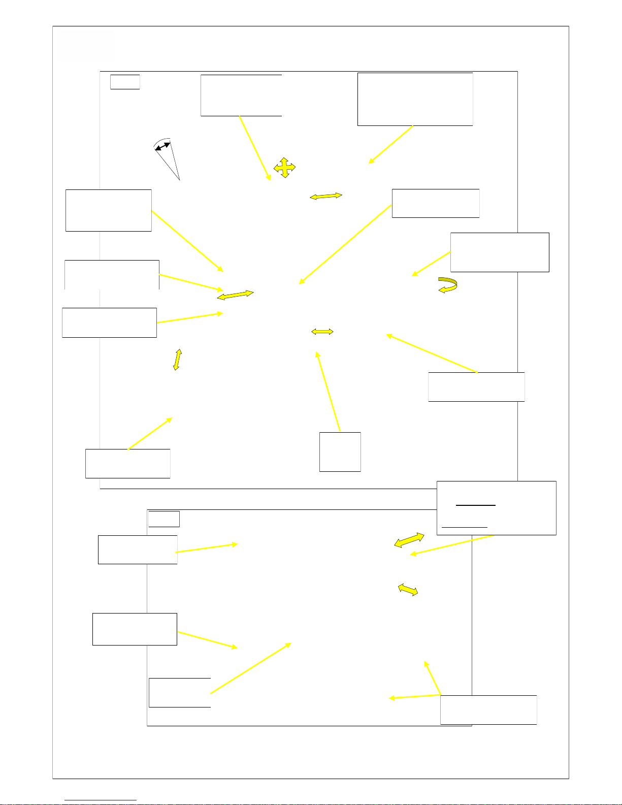
Main Component Identification and Location
Angle Adjustable Backrest Fig.1 12
Depth Adjustable Seat Fig.1 12
Height Adjustable Anti-Tippers Fig.1 12
Height Adjustable Armrests Fig.1 12
Manual Parking Brakes Fig.1 12
P & G VR2 Remote Controller Fig.1 12
Transportation Tie-down Points Fig.1 12
Battery Boxes Fig.2 12
Drive / Freewheel Selector Fig.2 12
Puncture-Proof Tyres Fig.2 12
Rear Suspension Fig.2 12
Width Adjustable Seat Frame Fig.2 12
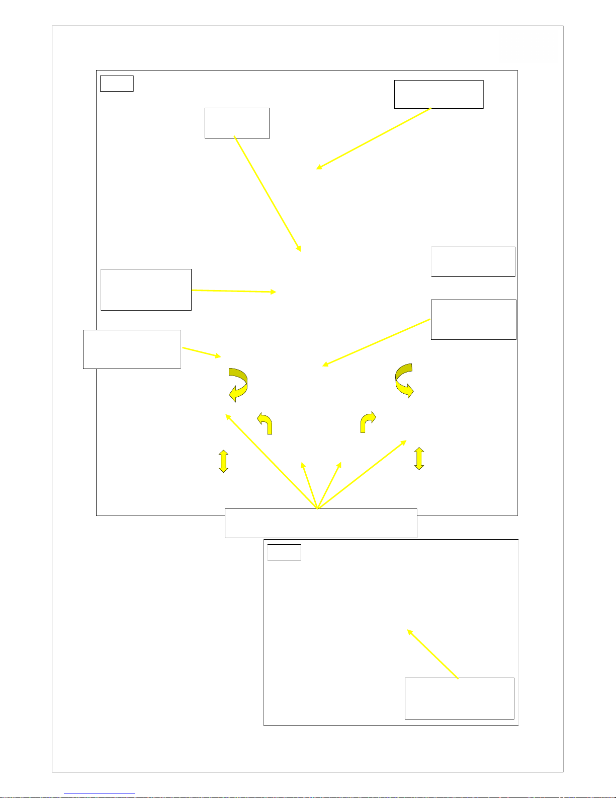
Footrest Hangers and Footrests Fig.3a 13
Lock Mechanism for Seat Base Fig.3a 13
Retaining Lap Belt Fig.3a 13
Seat Board and Cushion Fig.3a 13
Tension Adjustable Backrest Fig.3a 13
Serial Number Plate Location Fig.3b 13
Transportation
Transportation of the occupant, in a suitably
adapted motor vehicle, when seated in their
wheelchair. 14
Seating Adjustments
Seat
Seat Width 15
Seat Depth 16
Backrest Adjustments
Backrest Angle 17
Tension-adjustable Backrest 18-19
Footrests Adjustments
Footrest Hangers and Footrests 20-21
4
Page 5

Batteries
Remove and Refitting 22-23
Battery Gauge 24
Battery Charging 25
Used Battery Disposal 25
Remote Control Operation
General
Functions
Operation
Fault Diagnosis and Error Codes 28-31
Positioning adjustment for Comfort 29
Getting Ready to Drive 29
Driving Technique 30
Maintenance
Intervals 31-32
Parking Brake Adjustment 33
Inspection and Security of Drive Wheels 33
Inspection and Security of Front Castors 34
Inspection of Drive Motor Brushes 34
Anti-tip Device Adjustment 35
Standard Lap Belt Adjustment 35
Wheelchair Cleaning
Cleaning the Wheelchair 36
Cleaning the Upholstery 36
Wheelchair Disposal 37
Technical Data/Specifications 38-39
Wheelchair Accessory List 40
5
Page 6

Rehabilitation Manufacturing Services Limited would like to thank you for your
confidence in choosing an Invicta Powered Wheelchair. We hope you will enjoy
driving your new wheelchair and that it gives you many years of pleasurable
service.
The details contained in this manual, are intended to offer the User and Carer/
Attendants, sufficient information and instruction to enable the Invicta IPC-S and
IPC-T model wheelchairs to be used in a practical, supportive and safe way.
Following these instructions carefully, is an essential part of ensuring that this
electrically powered device is used correctly and safely.
Time should be taken to thoroughly read all sections of the manual and the User
should be given the necessary assistance and training to ensure that they are
totally familiar with the operational capabilities of the Invicta P17 wheelchair.
To assist the reader, pictorial examples accompany the text wherever possible.
In most cases, the name Rehabilitation Manufacturing Services Limited, will be
referred to in this manual as RMS Ltd.
Invicta IPC-S and IPC-T wheelchairs are intended for indoor use, with limited
outdoor use and is therefore classified as (Class B according to BS EN 12184).
They are intended for use by children and young adults who are unable to walk,
or have a walking impediment cased by paralysis, loss of limbs, limb defect/
deformity or joint contractures/joint damage.
Appropriate training of Users and Carers by suitably qualified personnel, is
essential to ensure correct and safe operation of the wheelchair.
Invicta IPC-S and IPC-T models must only be used in conjunction with approved
accessories, manufactured or supplied by RMS Ltd.
RMS Ltd. will accept no liability for personal injury, or damage to property,
where non-approved products have been used in association with any Invicta
wheelchair.
FORWARD
INTENDED USE
APPLICATION
The versatile Invicta IPC-S and IPC-T wheelchairs, have been designed specifically
for younger users with a range of disabilities. However, consideration must always
be given to certain aspects of powered wheelchair use, to ensure correct and safe
operation.
The user’s age, their physical and psychological capabilities and their physical
weight, i.e. Max.100Kg where no vehicular transportation is required, or 50Kg
where the occupant is to be transported in their wheelchair, in a suitably adapted
motor vehicle.
The use of a powered wheelchair is not recommended for persons with
strong balance disorders, severe limitations in cognitive abilities or reduced
or inadequate eyesight
The environment where the wheelchair is to be used also plays a large part in the
safe use of the wheelchair, serious consideration must be given to aspects such as
transferring to and from the wheelchair, general wheelchair access and facilities
within the home and school.
A suitably trained Carer may also take over driving control of the wheelchair, by
means of an optional attendant controller which can be mounted at the rear of the
wheelchair. (Part number IPC-4-01 price on application).
6
Page 7

Rehabilitation Manufacturing Services Limited, can only accept responsibility for the
safety, reliability and suitability, of the Invicta wheelchairs to which this document
relates, providing the device has been driven, used and maintained as
recommended in this “Instructions for Use” manual provided with the wheelchair.
Invicta powered wheelchair models, IPC-S and IPC-T together with any associated
approved accessories, are supplied with a warranty by RMS Ltd, against faulty
materials or workmanship under the following terms, conditions and periods:-
Chassis and Seat Frames — 24months
Drive components, Seating and Footrest components,
Electrical system and Batteries,
Accessories — 12months
As rates of wear and possible affects on the wheelchair by the user’s clinical
condition, are beyond the manufacturer’s control, items such as Upholstery and
Tyres will be classed as consumable items and will only be considered for repair
or replacement under warranty, where a failure is clearly identified as being a
direct result of a manufacturing or material defect.
The warranty will not cover any components or materials, which have been, in
the opinion of the manufacturer or his appointed agent, subjected to mis-use,
abuse, lack of maintenance as recommended in this manual, or conditions
beyond those for which the device was intended.
The warranty period will commence from the date of dispatch from RMS Ltd.
In the unlikely event of any parts becoming genuinely defective through faulty
materials or workmanship, during the warranty period, these will be replaced
without charge, by RMS Ltd. or their appointed agent.
Any displaced parts resulting from a warranty repair MUST be returned to RMS
Ltd. for inspection unless otherwise directed.
This warranty does not extend to any consequential costs from fault clearance,
carriage or travel costs, loss of earnings or expenses.
RESPONSIBILITY
WARRANTY Terms and Conditions
7
Page 8

SERVICE INFORMATION
CE DECLARATION of CONFORMITY
Any servicing or repairs on Invicta powered wheelchairs, should be carried out by
approved agents of RMS Limited or the supplying Wheelchair Service.
The RMS Technical Help-line can be contacted on 01634 578881 during normal
office hours, to give technical assistance in the event of a query or problem proving
difficult to resolve.
Please refer to Recommended Maintenance Checks and Adjustments on pages
31 to 35
To order genuine replacement parts or accessories for your Invicta wheelchair,
please contact sales at RMS Limited on 01634 578881 or [email protected]
Rehabilitation Manufacturing Services Limited confirms that:
Invicta Powered Wheelchair models IPC-S and IPC-T, marketed in the UK
solely by Rehabilitation Manufacturing Services Limited, conform to Class 1
requirements of Council Directive 93/42/EEC of 14th June 1993 concerning
medical devices.
Are in conformity with the provisions of that Directive and, where such is the
case, with the National Standards, transposing Harmonised Standards as noted
within the RMS Technical Data File No.39.
The requirements of Annex 1, Annex VII, Annex IX have been followed for Class
1 devices and the registration requirements of RMS Ltd as a manufacturer/
supplier of class 1 medical devices as Article 14, have been notified to the UK
Competent Authority.
In support of these requirements, RMS Ltd follows a quality management
system to ISO 9001:2008
The Declaration covers all Invicta Powered Wheelchair models IPC-S and IPC-T
placed on the market on or after 1st February 2011 and until such time as a
renewed conformity declaration is raised.
8
Page 9

GENERAL SAFETY INSTRUCTIONS
These Instructions for Use should be available to the User, or their
representative at all times.
In order for the User to gain maximum advantage from the Invicta wheelchair and
for it to be used as safely as possible, it is essential that the initial setting-up and
adjustment of the wheelchair components, together with the tuning characteristics
of the power drive controller, are carried out by suitably qualified personnel who will
ensure that the wheelchair is set to meet your individual requirements.
Where the User is taking medication, the prescribing doctor / physician should be
consulted to confirm that it is safe to drive the wheelchair whilst taking the
medication.
The wheelchair should never be driven by anyone under the influence of alcohol or
illegal drugs.
As the maximum speed of the Invicta IP models is 4mph they are therefore suitable
only for indoor use and for limited outdoor use on footpaths and designated
pedestrian areas. They are NOT suitable use on the public highway except for the
purpose of crossing the road at pedestrian crossings or wheelchair suitable points
where the kerbs have been lowered.
Wherever possible, traversing driveways, slopes and ramps should be avoided.
The maximum slope / ramp angle for driving up or down is 10°.
The maximum obstacle climbing height, is 50mm (2 inches).
To exceed either of these limits could severly affect the overall stability of the
wheelchair, causing it to tip and lead to possible injury to the User.
Do NOT exceed the maximum User weight limits of 100Kg (15.7stones) for nonvehicle transportable Users, or 50Kg (7.8 stones) for Users who are transported in
their wheelchair in a motor vehicle.
It is recommended that new powered wheelchair Users, take time to build up their
driving skills. Patience and Practice will be required by both Users and their
experienced Assistants, while learning various manoeuvres.
Navigating day to day obstacles with confidence, will be achieved with appropriate
training and practice.
The User should also be aware that, as the powered wheelchair operates very
quietly and is capable of travelling faster than some walking speeds, these aspects
could create a hazard to others especially in congested pedestrian areas.
Users of the IPC-T model Invicta with Power Tilt, should also be aware of the
following potential risks:-
1. There is a possibility of fingers being trapped, between the Sidearm Mounting
Bracket and Chassis Frame when the Seat is being lowered from a tilted
position. A Warning Label is applied to the Chassis Frame in this area to
warn of the risk.
2. There is also a potential risk of finger trapping at the rear of the Seat where the
Seat mounting brackets run on the actuator guides. A Warning Label is applied
to the Chassis Frame in this area to warn of the risk.
9
Page 10

Electro-Magnetic Interference
The Invicta IPC-S and IPC-T model wheelchairs have been successfully tested in
accordance with international standards as to their compatibility with (EMI)
regulations. However, electromagnetic fields, such as those generated by radio and
television transmitters and cellular phones, can influence electrically powered
vehicles.
To reduce the danger of Malfunction due to Electromagnetic Interference, the
following points should be noted:-
Portable communication devices such as Radio Transceivers, Cellular Phones
and “Walkie-Talkie” devices should not be operated in close proximity to the
wheelchair, whilst the wheelchair is “Swiched On”
Avoid getting into close range of powerful radio and television transmitters.
Should the wheelchair be set into unintentional motion, or the electro magnetic
brakes released unexpectedly, “SWITCH OFF” the wheelchair immediately.
By adding electrical accessories to your wheelchair or modifying the original
equipment electrical system could change the wheelchair’s susceptibility to EMI.
Both Invicta models are currently able to provide an immunity level of 20V/m
which should protect against common sources of EMI.
Any occurances of unintentional movement of the wheelchair, including
uncontrollable directional control, or unexpected release of the electromagnetic
brakes, should be reported to your wheelchair supplier as soon as possible.
Environmental Conditions
Environmental conditions may affect the safety and performance of your power
wheelchair. Water and extreme temperatures are the main elements that can cause
damage and affect the power drive performance.
Rain, Sleet and Snow — If exposed to water, the power drive system is
susceptible to damage to electrical or mechanical components. Water ingress
can cause electronic malfunction or promote premature corrosion of electrical
components.
DO NOT leave the wheelchair parked outside in the rain.
DO NOT park the wheelchair in a washroom/bathroom while taking a shower.
Temperature — Some parts of the power wheelchair are susceptible to changes
in temperature. The Controller can only operate within a temperature range
between 18°F (-8°C) and 122°F (50°C).
At extreme low temperatures, the batteries could freeze and the wheelchair may
not be able to operate. In extreme high temperatures it may operate at slower
speeds due to a safety feature within the Controller that prevents damage to the
drive motors and other electrical components.
Care must also be taken in hot weather. DO NOT leave the wheelchair parked
where it will be exposed to the sun, as the surfaces of the wheelchair can absorb
the heat and therefore become very hot to touch.
10
Page 11

Transferring to and from the Wheelchair.
Before attempting to transfer into the wheelchair, the following points should be
noted:-
To reduce the efforts sometimes required, to complete the transfer into a
wheelchair, it should be positioned as close as possible to the User’s position.
The power must be “Turned Off”.
The Free Wheel Lever set to the “Drive” (Forward) position and both Parking
Brakes applied. See Figs. 1 and 2.
Remove Armrests if required.
Raise both Footplates or swing-away both hangers. See Figs. 1 and 3.
Stability of the stationary wheelchair can be improved by pointing both Castor
Wheels towards the direction of transfer.
NOTE: Never use the wheelchair footplates to stand on during transfers.
Reaching and Leaning when seated in the Wheelchair.
The Pelvic Belt (Lap Belt) supplied with the wheelchair, should be the first thing
to be secured after entering the Wheelchair.
The User should never attempt to reach upwards or outwards for any object
which would require lifting their body weight off the wheelchair seat as this would
change the centre of gravity and could therefore affect the wheelchair stability.
Leaning forwards by the User, in an attempt to reach something on the floor in
front of the wheelchair, can also create a serious instability situation and must not
be attempted.
Excessive leaning sideways should also be avoided as this can affect the overall
lateral stability of the wheelchair, which could result in injury to the User, either by
tipping the wheelchair or becoming an obstacle to other people in congested
areas.
NOTES:
1. Do not hang heavy loads on the wheelchair backrest frames or push-handles
as this can seriously affect the rearward stability, especially when taking up
the drive on an incline (dynamic stability).
2. Correct use of the height adjustable rear Anti-Tippers, supplied as standard
with Invicta IPC-S and IPC-T models, is very important and these should be
positioned according to the environmental conditions where the wheelchair is
to be driven. (See page 35 relating to positioning Anti-Tippers)
11
Page 12
12
MAIN COMPONENT IDENTIFICATION
P&G VR2
Remote Controller with
Depth Adjustable
L or R Mounting
Manual
Parking
Brakes
Height Adjustable
Anti-Tippers
Height and Depth
Adjustable
Armrests
Rear Transportation
Tie-down Brackets
Angle Adjustable
Backrest
90° to 135°
Front Transportation
Tie-down Brackets
Puncture-Proof
Tyres Front & Rear
Two—31Amp/hr
Gel Batteries
Rear
Suspension
Adjustable Seat
Depth
Width Adjustable
Seat Frame
90°
135°
Fig.1
Fig.2
Release catch for
Swing-away
Footrest Hangers
Sidearm retaining
Thumb-screw
Move Drive Selector Lever
Forwards for Drive.
Push Lever inwards, then
Rearwards for Freewheel.
Page 13
Serial Number Location
The Serial Number of your
Invicta wheelchair, is located on
the inner face of the right-hand
Chassis member.
Always quote both numbers, in
any communication with RMS
Limited to enable us to identify
your specific model.
13
MAIN COMPONENT IDENTIFICATION
Fig.3a
Tension Adjustable
Backrest
Retaining Lap
Belt
Seat Board with
Velcro attached
Contoured Cushion
Lock Mechanism
for
Removable Seat
Swing-away Footrest Hangers with Flip-up,
Height and Angle Adjustable Footrests
Serial Number Located
on Inner face of RH
Chassis Member
Fig.3b
Height Adjustment
Armrests
Swing-away
Footrest Hangers
then lift to remove
Page 14
14
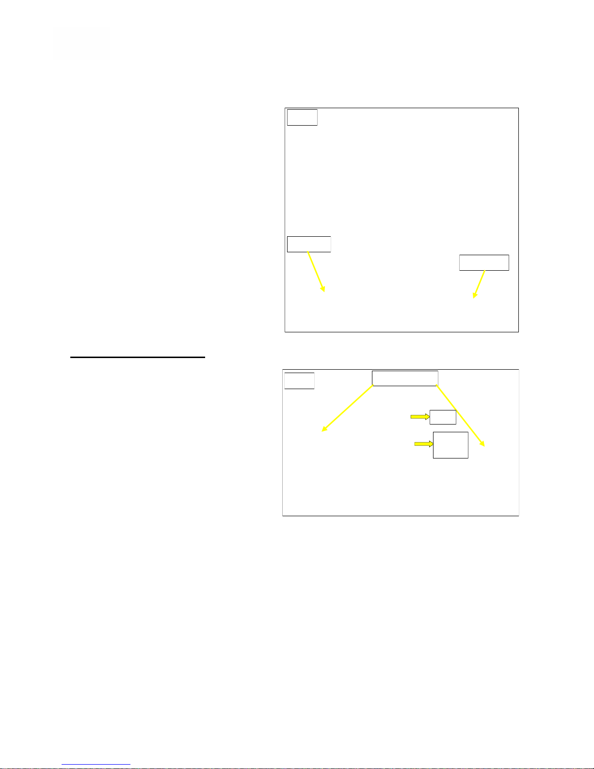
Transportation of the Occupant, in a suitably adapted motor vehicle, when seated in
their wheelchair. Models IPC-S and IPC-T
Both Invicta models, IPC-S (Tested as
P17R) and IPC-T (Tested as P17RT) have
been successfully tested, in the forward
facing mode, to ISO 7176 part 19, on the
1st September 2010, at the Transport
Research Laboratory, Berkshire, UK.
The tests were carried out using fixed 4point wheelchair restraint systems and
fixed 3-point occupant restraint systems,
tested to ISO 10542 and supplied by
Q-Straint.
The front and rear wheelchair restraint tiedown points, are clearly marked on the
chassis by standard Karabiner signs and
these are the only positions to be used in
transportation.
Under No circumstances should the wheelchair Lap or Pelvic Belt be used as the sole
method of occupant restraint.
The safe occupant weight limit for
transportation in the Invicta is 50Kg.
Although the Invicta Wheelchair “Crash
Tests” were carried out without using
Headrests, the use of these devices should
be optional, with the decision as to whether
it is necessary, being made by a suitably
qualified person following an individual risk
assessment.
The Wheelchair with Occupant should be positioned forward facing, centrally, over the tiedown tracks located on the transporting vehicle floor. Both Parking Brakes should be applied
and the Drive Selector Lever set to the “Drive” (forward position), as indicated in Fig.5
The WTORS (wheelchair tie-down and occupant restraint system) should be connected and
used in accordance with the manufacturers recommendations, see Fig.4 as an example.
TRANSPORTING THE INVICTA WHEELCHAIR
Tie-down Points
Apprx.45°
Apprx.35°
Fig.4
Fig.5
Drive
Apply
Brake
Page 15
15
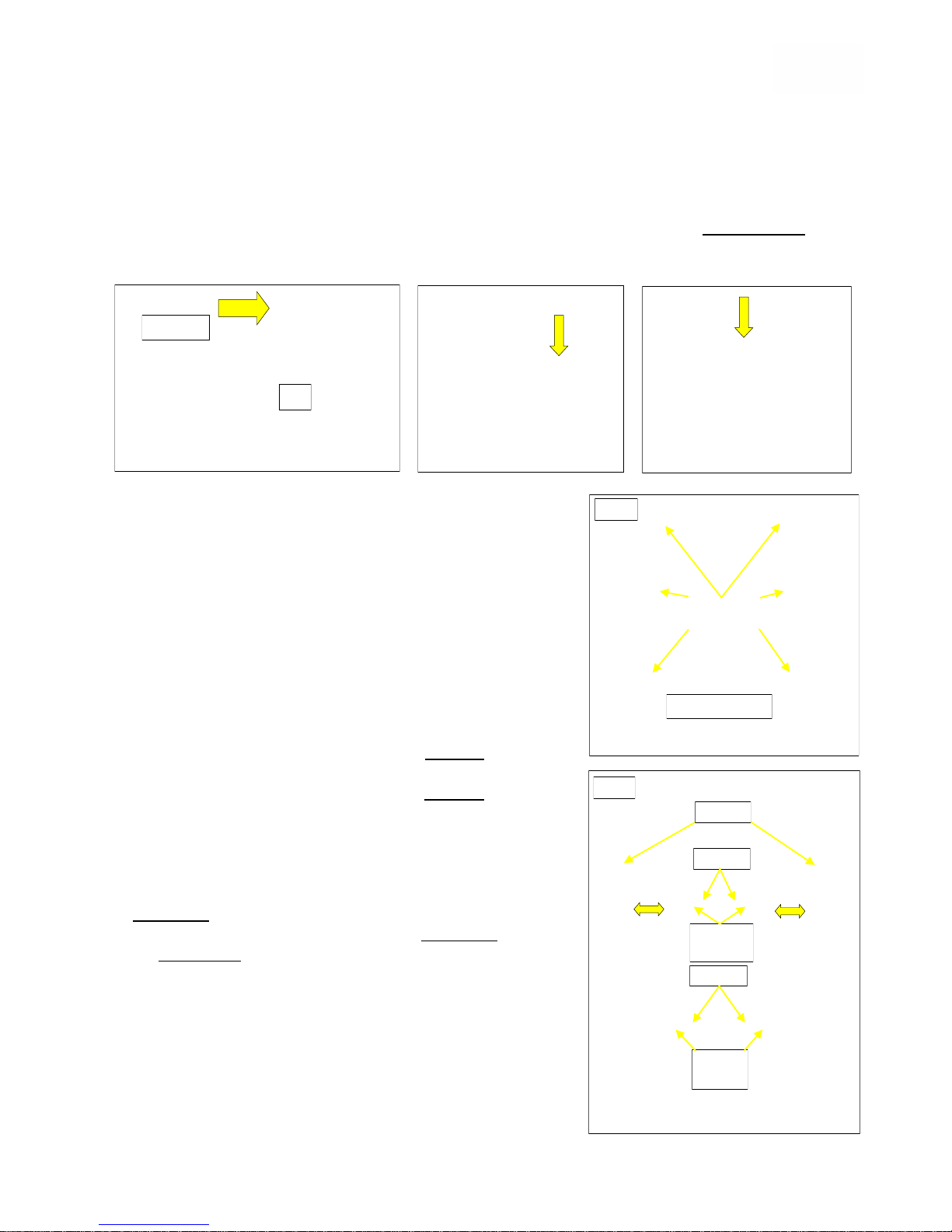
Seat Width Adjustment
Whilst the seating width and depth adjustments, will be factory set to the specifications
requested on the prescription form, there may be times where these need to be altered to
accommodate changes in the User’s growth, or their disability.
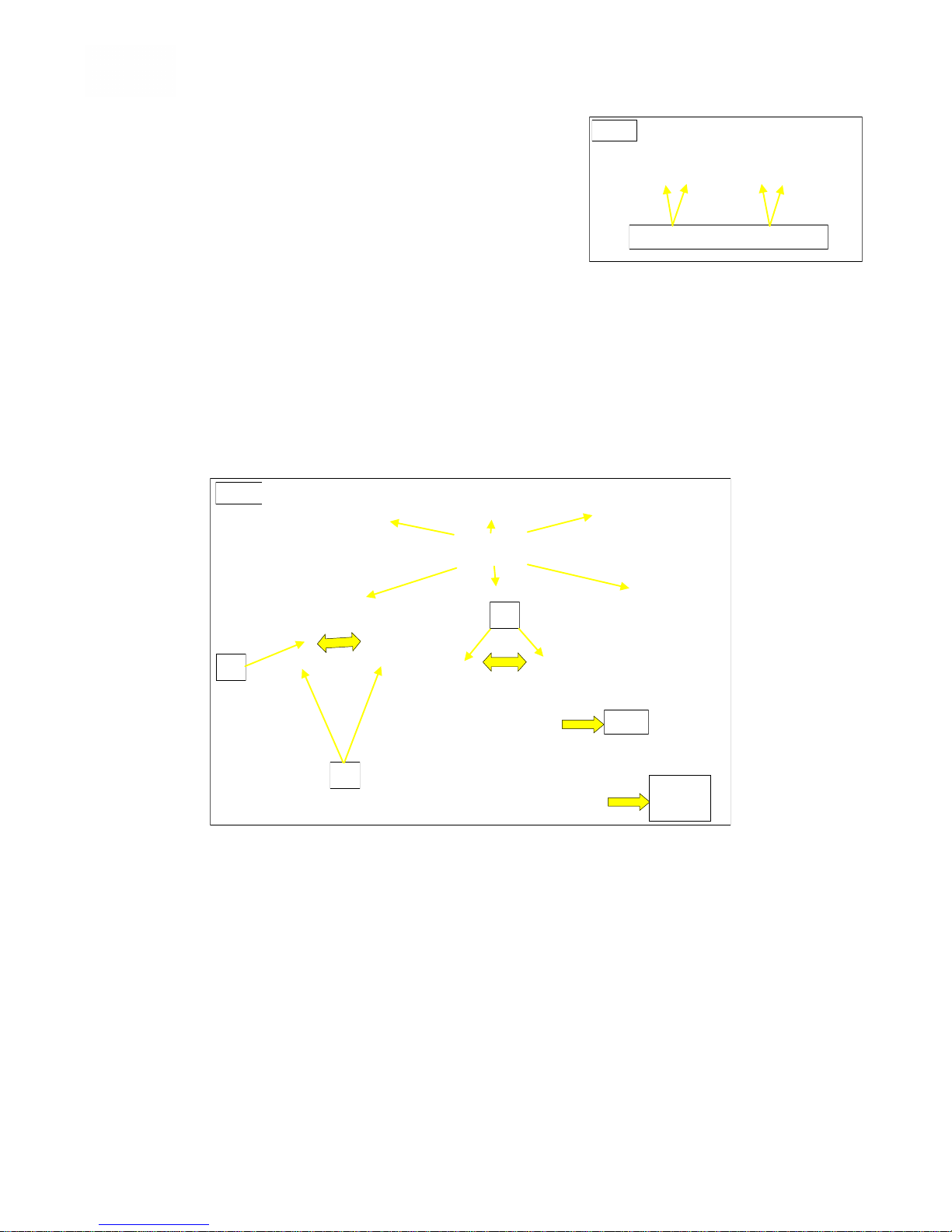
It will be necessary however, following the adjustments, to replace the Seat Board, Cushion and
Backrest, with the correct size to suit the new Seat width.
IMPORTANT NOTE: Where a 14" seat width is to be increased to 16" on a Powered Tilt model,
it will also be necessary to install the longer16" model rear Seat Locators and Front Seat Lock
Assembly, see below. (Please call RMS Sales for part numbers and prices).
Before commencing this procedure, the wheelchair should
be vacated and parked on a firm level surface, with both
Parking Brakes applied and Drive Selector Lever set to the
“Drive” position, Fig.5.
Tools Required:-
13mm Spanner, 4 and 6mm Hexagon Keys.
Remove Velcro attached Seat Cushion.
Remove Tension Adjustable Backrest Cover and unfasten
straps. Figs.12 -15.
For ease of working, remove both Sidearms and both
Footrest Hangers. Fig.1
Remove Seat Base Panel retaining screws x 6, Fig.6 and
lift Panel off Frame.
Remove screws and nuts (a) x 2 and slacken grub-screws
(b) x 2 from the front of the Seat Frame Fig.7.
Remove screws and nuts (c) x 2 and slacken grub-screws
(d) x 2 from the rear of the Seat Frame Fig.7.
Remove screws (e) x 2 from the Backrest Bracing Tube.
Fig.7.
Seat widths available = 300, 350 and 400mm. Therefore,
where the factory setting is 300mm, the width can be
increased to either 350 or 400mm. Where the factory
setting is 350mm, the width can be increased to 400mm
or decreased to 300mm. 400mm being the maximum
width.
The adjustment is made, by sliding the Outer Frame
sections either inwards or outwards until the front and rear
screw holes are appropriately aligned, Fig.8 overleaf.
Reinstall Frame screws and nuts in the reverse order of
dismantling and retighten sufficiently to prevent any
movement. Reinstall both screws (e) Fig.7, into the
Backrest Bracing Tube and tighten sufficiently to prevent
any movement. [Cont]
SEAT and BACKREST ADJUSTMENTS
Retaining
Screws
Grub-
screws d
Screws a
Screws c
Grub-
screws b
Screws e
Fig.6
Fig.7
SEAT BOARD
12 & 14"
16"
Page 16
16
Reinstall both screws (e) Fig.7, into the Backrest Bracing
Tube and tighten sufficiently to prevent any movement.
Install the new width Seat Board using the original screws.
Fig.6.
Adjust Tension Adjustable Backrest as required and refit
Cover, Figs. 12 -15.
Refit Sidearms, Footrest Hangers and Seat Cushion. Fig.1
Seat Depth Adjustment
Seat depth is adjustable by positioning the Backrest in relation to the Seat Frame.
The Backrest is attached to the Seat Frame via a Connecting Bracket (a) Fig.16 and a series of
holes along each side of the Seat Frame, that allow the Backrest to be mounted further forwards to
reduce the Seat depth, or rearwards to increase the Seat depth. Mounting holes are spaced at
25mm centres.
Before commencing this procedure, the wheelchair should be vacated and parked on a firm level
surface, with both Parking Brakes applied and Drive Selector Lever set to the “Drive” position,
Fig.16. Tools Required:- 13mm Spanner, 4 and 6mm Hexagon Keys.
For ease of working, remove both Sidearms. Fig.1
Remove Velcro attached Seat Cushion.
Remove Seat Base Panel retaining screws x 6, Fig.9 and lift Panel off Frame.
Remove both retaining screws and nuts (b) from the Backrest Connecting Brackets (a) on each
side of the Seat Frame. Fig.9
Move Backrest to the new required position and reinstall original screws and nuts (b). Tighten
nuts sufficiently to prevent any movement.
NOTE: By moving the Backrest position, may subsequently require the Sidearm
Mount positions to be moved to achieve correct Sidearm support.
Reposition Sidearm Mounts, by removing both screws and nuts (c) Fig.9
Move Sidearm Mounts to the new required position and reinstall original screws and nuts (c).
Tighten nuts sufficiently to prevent any movement.
Reinstall Seat Panel using original screws and tighten sufficiently to maintain its position.
Refit Sidearms to Mounts and refit Seat Cushion.
Fig.9
Retaining
Screws
(b)
(a)
(c)
Drive
Apply
Brake
Fig.8
Alternative adjustment positions
Page 17
17
Adjusting Backrest Angle
Tools Required: 13mm Spanner and 6mm Hexagon Key.
Before commencing this procedure, the wheelchair should be vacated and parked
on a firm level surface, with both Parking Brakes applied and Drive Selector Lever
set to the “Drive” position, Fig.9.
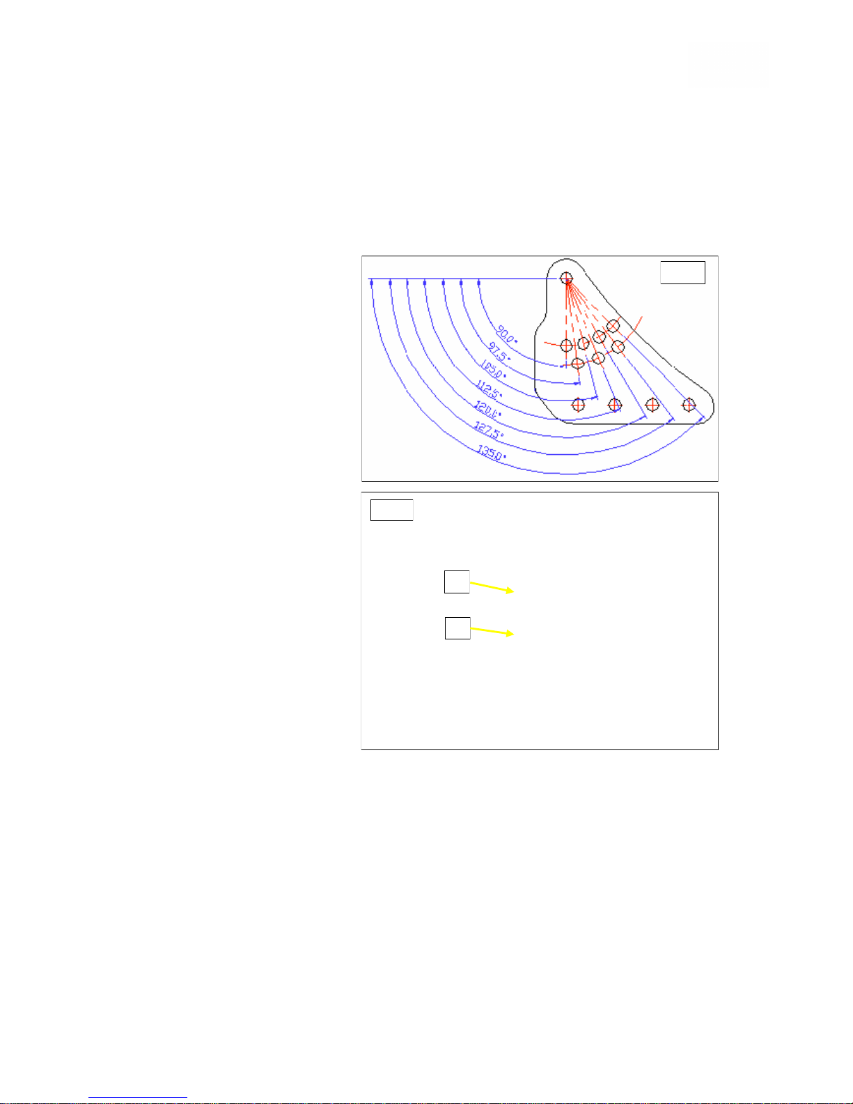
The Backrest angle is adjustable in 7.5° increments. A series of holes in the
Backrest Connecting Brackets allow adjustment to be made from 90° to 135°
Fig.10.
Adjustment is made by
slackening screws (a) Fig.18
and removing screws (b) to
allow the Backrest to pivot
around screw (a) until one of
the two holes in the lower
Backrest Frame, aligns with
the appropriate angled hole
in the Connecting Bracket
Fig.11.
NOTE: It may be necessary to
reposition the Pelvic Belt
mounting point to another
vacant hole to achieve the
required Backrest position.
Re-insert screws (b) on both
sides and secure by
tigh t e ning the n uts
sufficiently to prevent any
movement.
NOTE: Ensure screws (b) are
inserted in the same adjustment
hole position on each side.
Fig.10
(a)
(b)
Fig.11
Page 18
18
Adjusting Tension-adjustable Backrest
No Tools are Required for this procedure.
Before commencing this procedure, the
wheelchair should be vacated and parked on
a firm level surface, with both Parking Brakes
applied and Drive Selector Lever set to the
“Drive” position, Fig.9.
Remove Headrest if applicable
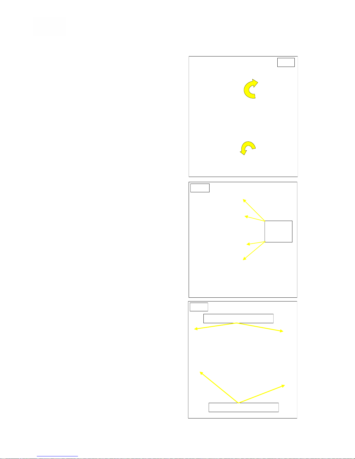
Adjusting the Tension-adjustable Backrest
will require removal of the Velcro attached
Padding Cover Fig.12. This will expose the
upper and lower Adjustment Panels Fig.13
Each support strap can be adjusted
individually by releasing the Velcro contact
area, setting the strap to the length
required and re-connecting via the Velcro
areas.
Re-install the Backrest Padding Cover,
starting by attaching the narrow Sacral
Pad against the front of the Backrest as
Fig.12. Continue, by routing the Padded
panel, with motive Fig.14, upwards at the
rear of the Backrest towards the top.
Finally, folding the last panel over the top
of the Backrest and securing to the front of
the via the Velcro panels.
———————
Where the wheelchair is to be used with an
alternative contoured Backrest, the Tensionadjustable Backrest will have to be removed.
If the original Backrest is to be discarded
once removed, then it can be cut off the
Backrest Frame after removing the two
retaining screws from the upper and lower
panels.
If the Tension-adjustable Backrest is to be
stored after removal, for re-use at a later
date, this will involve disconnecting the
Backrest Frame from the wheelchair.
Tools Required:- 13mm Spanner, 4 and
6mm Hexagon Keys.
Remove the Backrest Padding Cover.
Remove two retaining screws from the
upper Adjustment Panel Fig.14 and
manoeuvre the Panel upwards and over
the Push handles to remove.
[Cont]
Fig.13
Fig.12
Adjustable
Support
Straps
Fig.14
Upper Panel retaining screws
Lower Panel retaining screws
Page 19

19
Remove both retaining screws from the
lower Adjustment Panel.
Before Removing the nuts and screws (a)
from each side of the lower Backrest
Frame Fig.15, note which mounting holes
were being used in the Connecting Plates,
to ensure the Backrest is refitted to the
same angle as before.
With the Frame disconnected, lift clear and
slide lower Adjustment Panel off the
Frame.
Re-install Backrest Frame to the
Connecting Plates using the original
screws and nuts. Tighten sufficiently to
prevent any movement.
NOTE: Alternative Backrests should be installed onto the Invicta Backrest Frame
in accordance with the instructions supplied with that device.
Fig.15
Retaining Screws
Nuts and
Screws (a)
Page 20
20
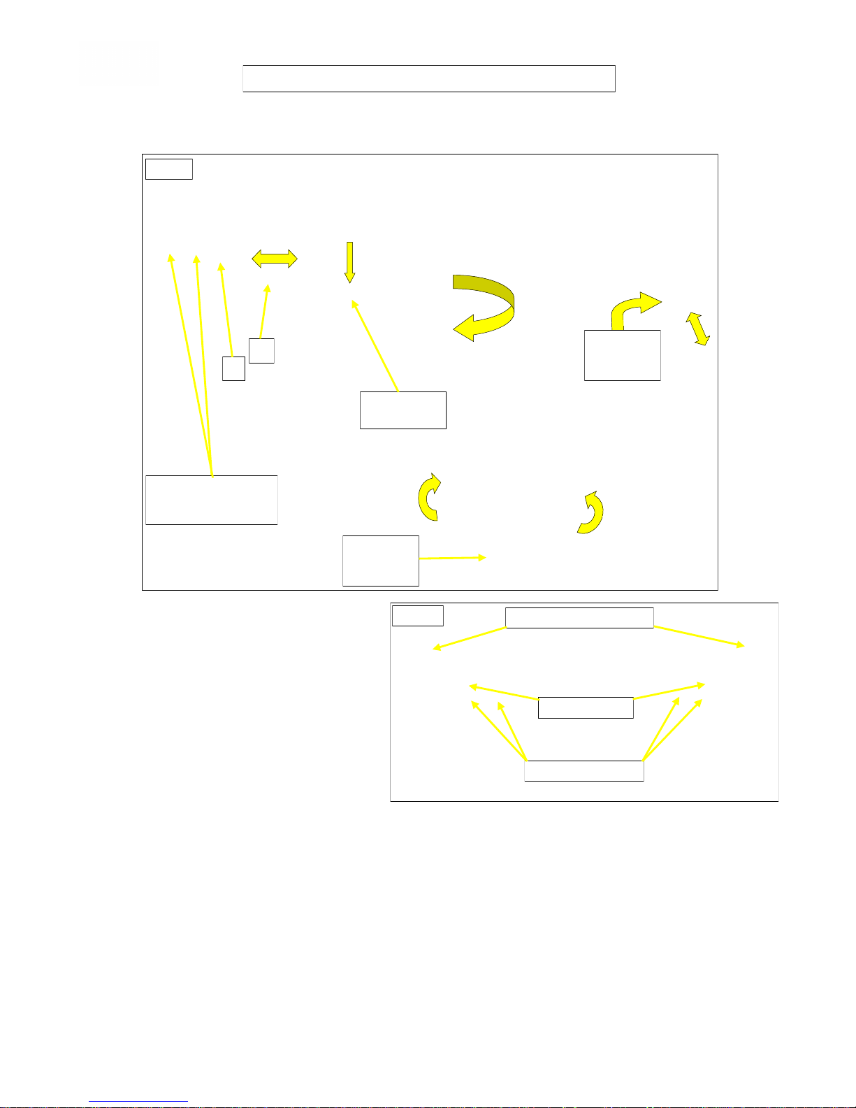
Both Invicta “S” and “T” models are equipped with depth adjustable, swing-away,
Footrest Hangers, with flip-up, height and angle adjustable Footrests. Fig.16.
Footrest Hanger depth
adjustment:
Tools Required:- 13mm Spanner,
4 and 6mm Hexagon Keys.
Before commencing this procedure,
the wheelchair should be vacated
and parked on a firm level surface,
with both Parking Brakes applied
and Drive Selector Lever set to the
“Drive” position, Fig.9.
For ease of working, remove
both Hangers and Footrests from the wheelchair, leaving just the Hanger Mounts
attached to the Seat Frame, Fig.17a
Remove screws and nuts (a) and slacken grub-screws (b).
Slide Hanger Mount in or out of the Seat Frame to the nearest required position
to allow alignment of mounting holes.
Re-install screws and nuts (a) to finger tight. Fully tighten grub-screws (b), then
fully tighten screws and nuts (a) sufficient to prevent any movement.
Re-install Hangers and Footrests.
[Cont]
FOOTREST HANGERS and FOOTPLATES
Fig. 16
Alternative depth
adjustment positions
For Hanger Mounts.
(a)
(b)
Angle
Adjustment
Lock-screw
Height
Adjustment
Lock-screw
Swing-away
Release catch
Fig. 17a
Screws and nuts (a)
Grub-screws (b)
Outrigged Hanger Mounts
Page 21
21
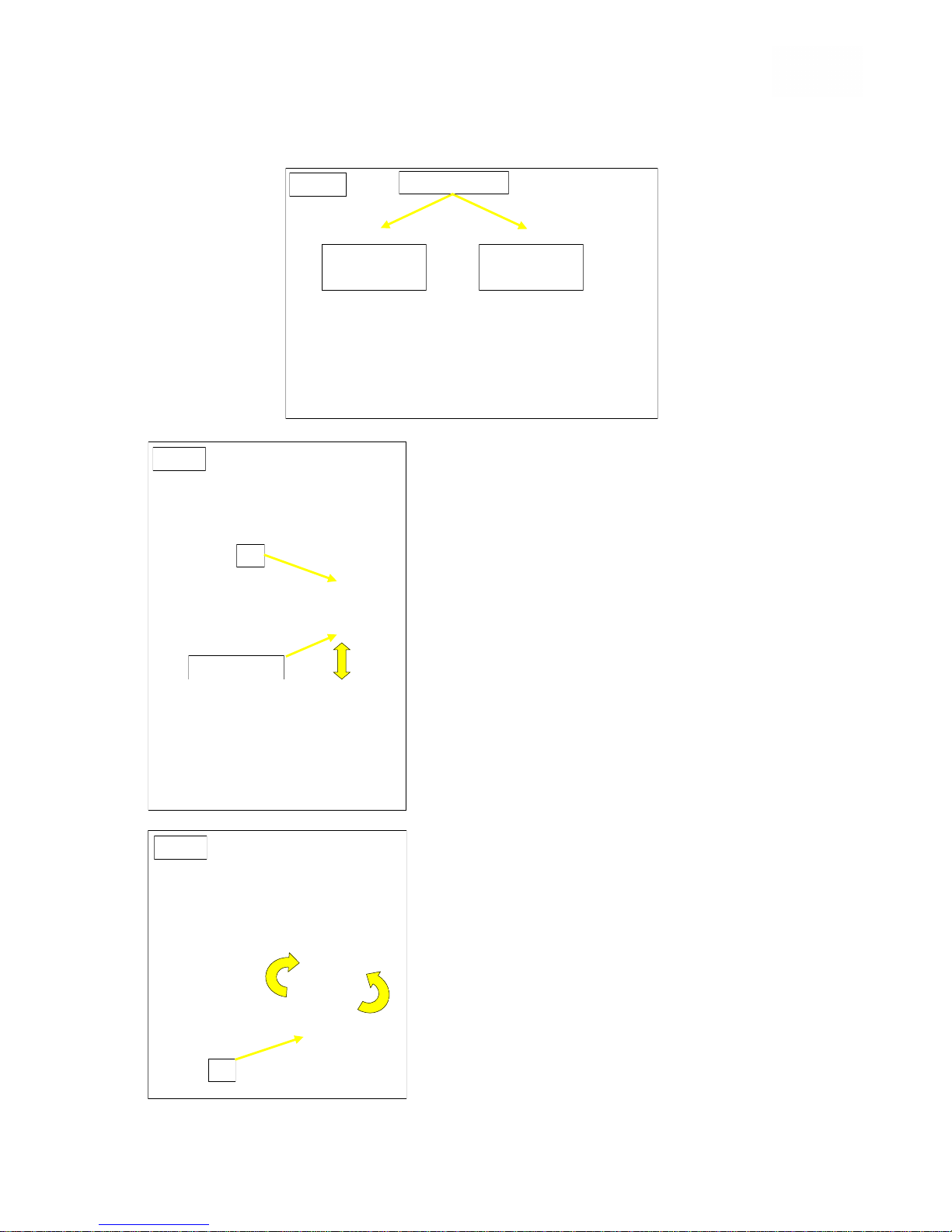
NOTE: To create sufficient clearance between Footrests when the seat width is set
to 300mm, outrigged Footrest Hanger Mounts are used, Figs.17a & 17b.
Footrest Height adjustment:
This procedure can normally be carried out with
the User seated.
Tool Required: 4mm Hexagon Key.
Slacken grub-screw (a) Fig.18.
Adjust Footrest to height by sliding the
Footrest Stem upwards or downwards, within
the Hanger to the required position.
Re-tighten grub-screw sufficiently to prevent
movement.
NOTE: Ensure there is at least 40mm of Footrest
Stem inside the Hangers before tightening grubscrews.
Footrest Angle adjustment:
This procedure can normally be carried out with
the User seated.
Tool Required: 4mm Hexagon Key.
Slacken locking screw (b) Fig.19.
Adjust Footrest angle, by revolving the
Footrest around its pivot to the required
position.
Re-tighten locking screw sufficiently to prevent
movement.
Fig. 18
(a)
Footrest Stem
Fig. 19
(b)
Fig. 17b
Hanger Mounts
350 & 400mm
Seat Widths
300mm
Seat Width
Page 22
22
Both the IPC-S and IPC-T Invicta models, are equipped with two 12volt, 31Ah GelCell Batteries, connected in series.
Their maximum driving range is 15miles, but this can vary depending on driving
conditions.
As they are not designed to be frequently removed and refitted they would normally
only require removal for fault diagnosis, maintenance or replacement.
WARNINGS:
Other than for testing purposes by suitably trained personnel, always
ensure the power is turned “OFF” before any maintenance is carried out on
the wheelchair, especially where removal of the Batteries is required.
Batteries - Removal and Refitting.
Before commencing this procedure, the wheelchair
should be vacated and parked on a firm level surface,
with both Parking Brakes applied and the Drive Selector
Lever set to the “Drive” position, Fig.9.
Disconnection and removal of the Batteries will require
removal of the Seat Unit from the wheelchair.
Tools Required: 2 x 10mm Spanners
Please follow instructions:-
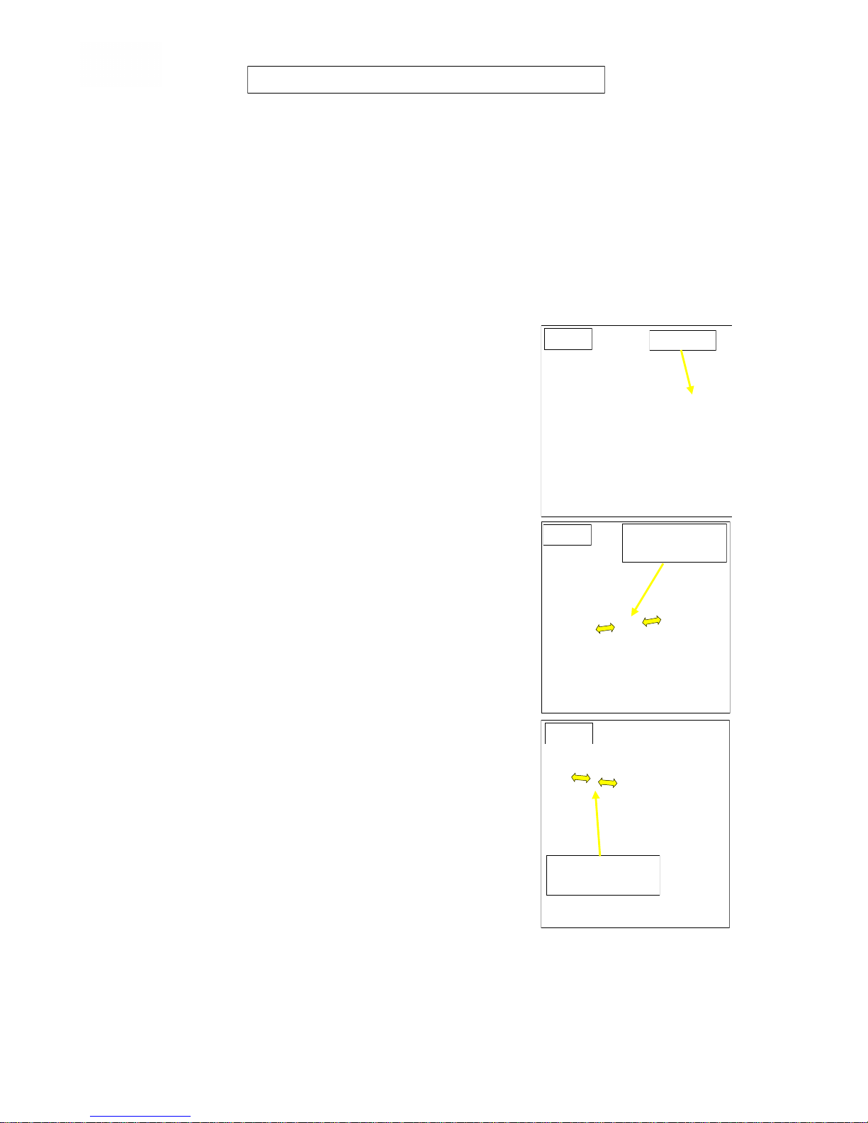
Turn “OFF” power at the Remote Controller Fig.20.
Disconnect the Remote Control Cable from the Power
Base loom at the grey/black connector, Fig.21. The
Power Tilt Actuator Cable on the IPC-T model, must
also be disconnected at the white/black connector
Fig.22. Both located just forward of the rear main
Chassis.
Remove both Sidearms complete with the Remote
Controller Fig.8. NOTE: If the Wheelchair is fitted with
an activity/feeding Tray, this must be removed prior to
removing the Sidearms.
Disconnect and remove both Footrest Hangers. Fig.9.
Unscrew the front Seat Retaining Screw, located
behind the front Seat Mount, Fig.3a, sufficiently to
allow the front of the Seat to be lifted.
With one person standing either side of the
wheelchair, the Seat Unit can be lifted upwards and
forwards, clear of the Power Base.
The Batteries are housed in Battery Boxes which are
supported on the wheelchair by two tubular rails
attached to the Frame and retained by Nylon webbing
straps, secured by Velcro and a rear bracket retained by
two hand screws. Figs.23 and 24
Release front and rear Battery Box straps (a) and (b)
Fig.23 at the Velcro panels. (Not the Battery Box Cover straps Fig.25)
As straps (c) and (d) Fig.31, are attached to the Battery Box retaining bracket
these will be released when the hand screws and bracket are removed.
[Cont]
BATTERIES REMOVE and REFITTING
ON / OFF
Fig. 20
Remote Control
Cable connector
Power Tilt Cable
Connector
Fig. 21
Fig. 22
Page 23
23
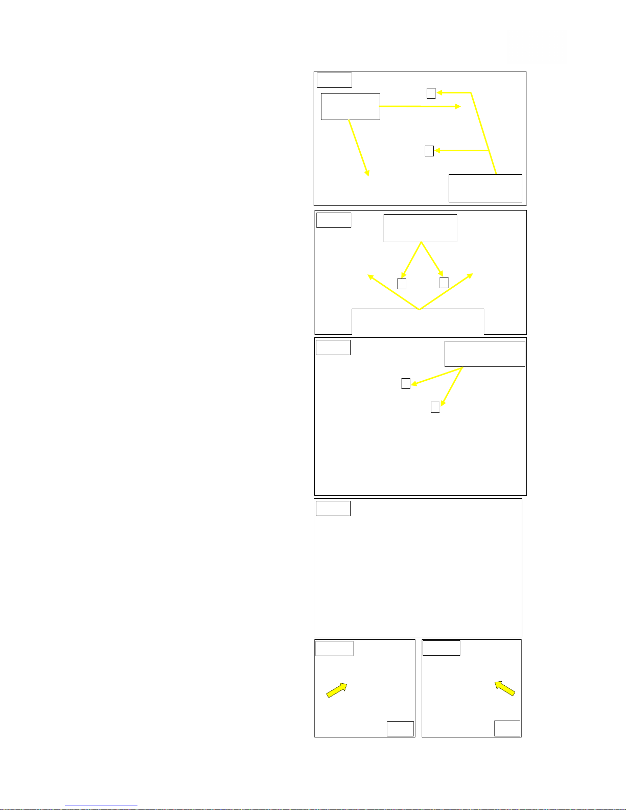
Each Battery Box can now be removed
from the wheelchair by sliding the Box
along the supporting rails and out from
the rear of the wheelchair Fig.25.
The individual Batteries can then be
accessed, by releasing the strap
buckles (e) Fig.25, retaining the
Battery Box Covers and removing the
Covers.
Disconnect the power cables from the
Batteries and lift Batteries out from
their Boxes.
IMPORTANT NOTE: If the Batteries are
to be replaced, the new ones must be of
the same type, physical size, capacity
and terminal configuration. It is
recommended that both Batteries are
replaced at the same time and ideally,
they should be fully charged by the
supplier before installation.
Ensure Main Battery Cables are correctly
connected to the Batteries and the
terminal screws are fully tightened. Fig.26
Re-installation of the Batteries is by the
reverse, step by step, of the removal
procedures.
On completion of reassembly and final
connection of cables, ensure the Drive
Selector Lever Fig.2, is set in the forward
“Drive” position and the Manual Parking
Brakes are applied. Switch “ON” the
power at the Remote Controller Fig.20,
(ensure Joy Stick is in the central
position) to check the Battery charge
level on the indicator. Figs.27a, b and c.
Each Battery Box is fitted with an
overload Reset Button, Figs 26a and 26b.
As these are safety devices, if either
device trips-out more than once, then try
to note what was operating when it
tripped-out as this may assist with fault
diagnosis.
The Buttons can be reset by depressing,
after the fault has been rectified.
[Cont]
Main Battery
connectors
Fig. 23
Fig. 24
Battery Box
retaining straps
Battery Box
retaining straps
Battery Box retaining bracket
with hand screws
a
b
c
d
Fig. 25
Battery Box Cover
Retaining Straps
e
e
Fig. 26
Fig. 26a
Fig. 26b
Front
Rear
Page 24
24
The Battery Gauge
The Battery Gauge is to let you know how much charge is left in your Batteries.
The best way to use the gauge, is to learn how it behaves as you drive the
wheelchair. Like the fuel gauge in a motor car, it is not totally accurate, but it will
help to avoid running out of “charge”.
The gauge works in the following way:-
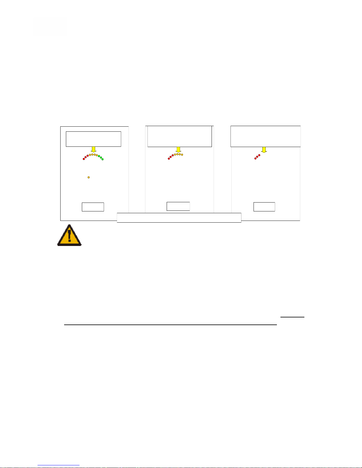
When you switch the system “ON”, the gauge shows an estimate of the remaining
Battery charge. Figs.27a, 27b and 27c
The Battery gauge will however, gives a more accurate reading, approximately one
minute after you start driving the wheelchair.
DO NOT operate the control system if the Batteries are nearly discharged,
as failure to comply with this warning may leave the User stranded in an
unsafe position i.e. in the middle of a road or busy shopping walkway.
Neither RMS Ltd, or PG Drives Technology, will accept any liability for loss or
damage of any kind arising from failure to comply with this WARNING.
IMPORTANT INFORMATION:
The Battery Gauge also has built-in status indication with the following signals:-
Battery Gauge is Steady—This indicates that all is well.
Battery Gauge Flashes Slowly–The control system is functioning correctly, but
you should charge the batteries as soon as possible.
Battery Gauge Steps Up–The wheelchair Batteries are being charged. You will
not be able to drive the wheelchair, until the Charger is disconnected and you
have switched the Controller “OFF” and then back “ON” again.
Battery Gauge Flashes Rapidly (even with the Joystick released) - The control
system safety circuits have operated and the control system has been prevented
from allowing the wheelchair from moving. This indicates a system trip, i.e. the
VR2 has detected a problem somewhere in the wheelchair’s electrical system.
Please follow this procedure:-
1. Switch “OFF” the control system.
2. Make sure that all external cable connections on the wheelchair are correctly
connected and secure.
3. Check the Battery condition.
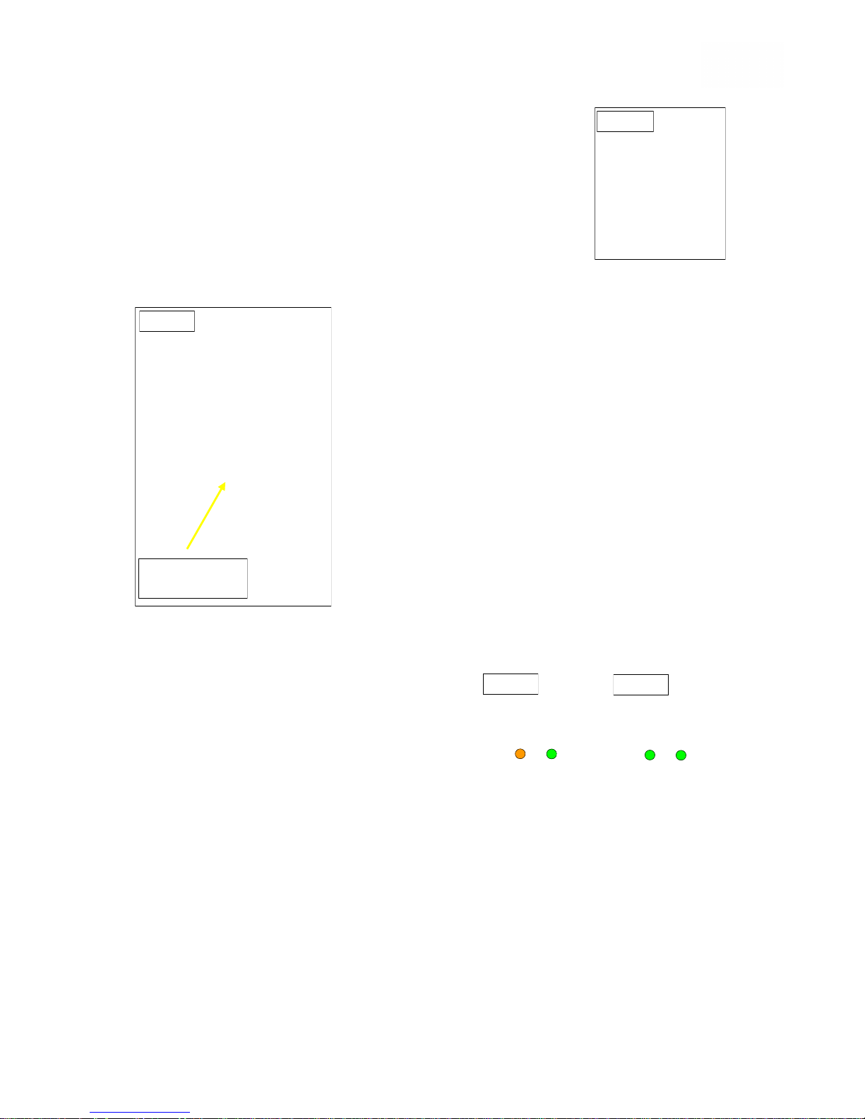
All Lights “ON”
Batteries fully Charged
Red and Amber “ON”
Charge Batteries as soon
as you can
Red only “ON”
Steady or Flashing
Charge Batteries immediately
VR2 Remote Control as supplied on IPC-T
Fig. 27c
Fig. 27b
Fig. 27a
Page 25
25
Charging the Batteries
Only use the Charger supplied with the wheelchair.
Your Charger is equipped with dual voltage, (i.e.115v and 230v)
ensure the Charger is set to the appropriate voltage compatible
with your Mains Supply, Fig.28a.
The Charger is intended for interior use only and must be
protected from moisture. Always charge your Batteries in a well
ventilated area.
If the wheelchair is to be taken out of service for a long period of
time, it is recommended that arrangements are made for the Batteries to be
charged at least once every month.
Depending on the condition of the Batteries, charging
can take between 4 and 10 hours to fully charged. This
will be indicated by the light status on the charger end
panel, changing to green.
NOTE: Charging for longer than necessary will not
harm the Batteries, however, it is recommended that
the Batteries are charged for 8 to 10hours after daily
use, but not charged continuously for more than
24hours.
Charging Instructions
Park your wheelchair close enough to a Mains power
socket outlet, to enable the Charger mains cable to
reach the socket and the Charger power cord (with
round plug) to safely reach the socket on the underside
of the Remote Controller, Fig.28b.
Connect the Charger Power Cable to the Remote Controller, Fig.28b and plug
Mains cable into the Mains 240v socket. Switch-on at the socket.
One Orange and one Green light will illuminate when the Charger is switched “ON”,
Fig.29a.
When the Orange light changes to Green, the
charging process is complete, Fig.29b
The Green power light will stay “ON” until the
power is disconnected and the Charger power
cord is removed from the wheelchair.
Please also refer to the instruction sheet
supplied with Battery Charger.
Disposal and Recycling of used Batteries and Electrical Equipment
Batteries and Electrical Equipment must always be correctly recycled and
under no circumstances should they be disposed of with domestic refuse.
You can assist in helping to preserve the environment by returning your
used Batteries or Electrical Equipment to your local approved collection
and recycling point, which is normally run by your local council.
For information on the location of your nearest Battery recycling point,
please contact your local government authority.
RMS Ltd is an environmentally aware supplier that complies wherever
possible with the WEEE Directive 2002/96/EC.
Charger Power
Cable
Fig. 28b
Fig. 28a
Fig. 29a
Fig. 29b
Page 26
26
REMOTE CONTROL OPERATION
Introduction
Operation of the VR2 wheelchair Control System, is simple and easy to understand.
The Control System incorporates State-of-the-Art electronics, the result of many
years of research, to provide you with ease of use and very high level of safety.
In common with other electronic equipment, correct handling and operation of the
unit will ensure maximum reliability.
Please read the information in this chapter carefully—It will help you to keep your
wheelchair reliable and safe.
General
Avoid knocking your Control System and especially the Joystick. Be careful not to
strike obstacles with the Control System or Joystick when you drive. Never drop the
Control System.
When transporting your wheelchair, ensure the Control System is well protected
and avoid damage to cables.
Your Control System uses industrial-grade components throughout, ensuring
reliable operation in a wide range of conditions. However, you will improve the
reliability of the Control System if you keep exposure to extreme conditions to a
minimum.
Do not expose the Control System or its components to damp for prolonged
periods.
If the Control System becomes contaminated with food or drink, this should be
cleaned off as soon as possible.
Clean the Control System and the Joystick with a cloth dampened with diluted
detergent. Be careful when cleaning the Joystick—Ensure the power is turned
“OFF”. Never use abrasive or spirit-based cleaners.
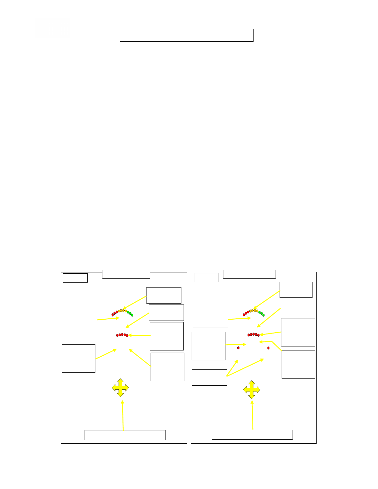
Fig. 30a
Fig. 30b
“ON” / “OFF”
SWITCH
“ON” / “OFF”
SWITCH
HORN
BUTTON
HORN
BUTTON
BATTERY
GAUGE
BATTERY
GAUGE
MAX
SPEED
PROFILE
INDICATOR
MAX
SPEED
PROFILE
INDICATOR
SPEED
PROFILE
DECREASE
BUTTON
SPEED
PROFILE
DECREASE
BUTTON
SPEED
PROFILE
INCREASE
BUTTON
SPEED
PROFILE
INCREASE
BUTTON
ACTUATOR
BUTTONS
DIRECTIONAL JOYSTICK
Model VR2 JSM
Model VR2 JSM-A
DIRECTIONAL JOYSTICK
Page 27
27
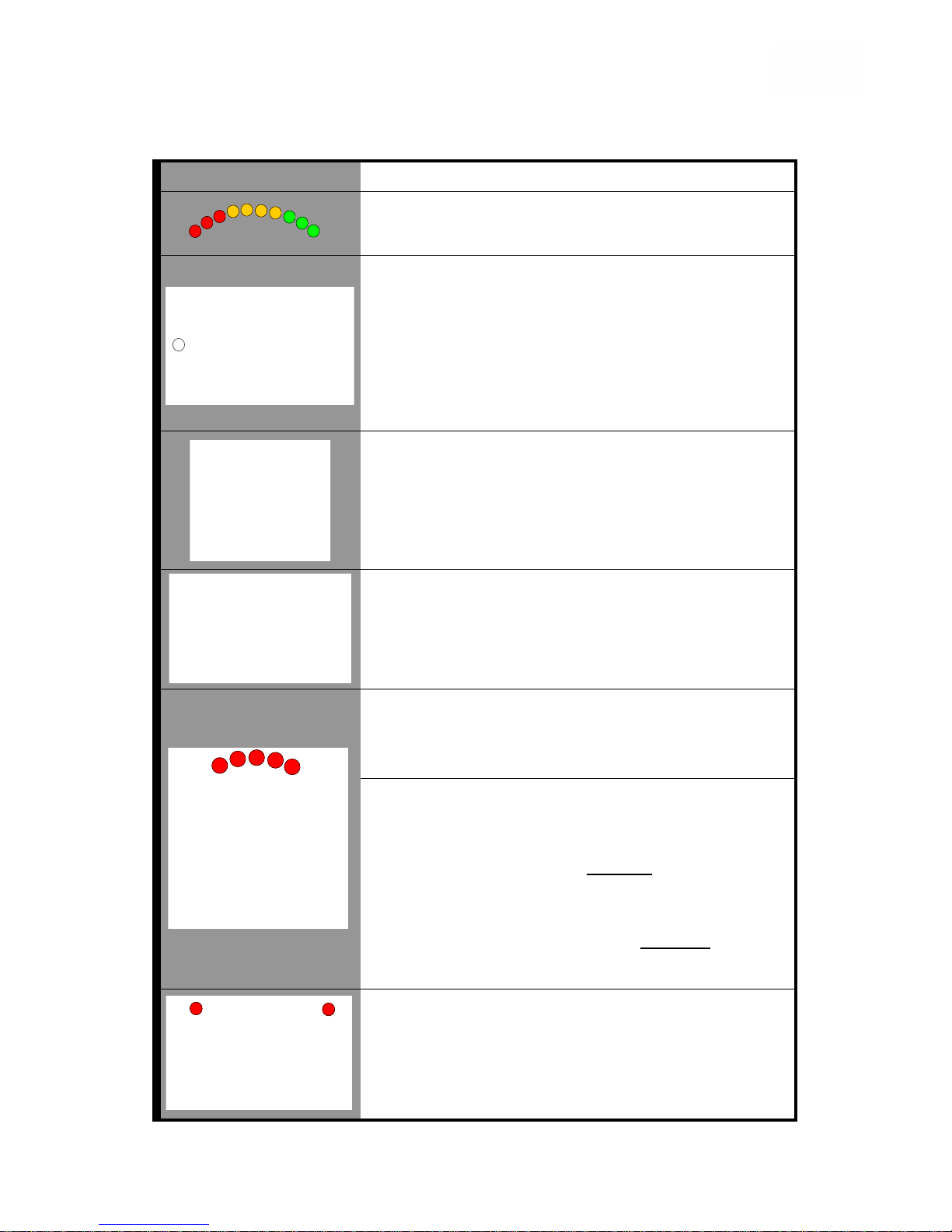
Symbol Identification and Operational Information.
Refer also to Figs.30a and 30b on page 26 and the diagnostic table on page 28.
Symbol Details
The Battery Gauge shows that the wheelchair is switched
“On”. It also indicates the operating status of the
wheelchair.
The “ON / OFF” Button is operated by depressing the
button once to switch the power “ON” and depressing the
button again to switch the power “OFF”.
When switched “ON”, this applies power to the Control
System electronics, which in turn supplies power to the
wheelchair’s motors.
Unless there is an emergency, DO NOT use the “ON /
OFF” button to stop the wheelchair, as this could shorten
the life of the drive components.
The Joystick primary function is to control the speed and
direction of the wheelchair. The further you push the
Joystick from the centre position, the faster the wheelchair
will move. When the Joystick is released, the brakes are
automatically applied.
If the wheelchair is fitted with an actuator, the Joystick may
also be used to select the actuator direction.
The Horn Button will sound the horn when the button is
depressed.
The Profile Indicator is an indicator that shows the
selected drive profile. There may be up to five profiles
available, this depends on the programming of the Control
System.
The Maximum Speed / Profile Indicator is a gauge that
shows the maximum speed setting for the wheelchair or, if
the Control system is programmed for drive profile
operation, the selected drive profile.
Speed Profile Buttons—To increase the speed profile,
depress the Right-hand Button once for each speed range
increase. The indicator lights will inform you of the current
level range setting.
Depressing the Left-hand Button will decrease the speed
range one level for each depression.
The Actuator Buttons allow the User to depress either
Button to enter the adjustment mode and this will be
indicated by illumination of both actuator LEDs.
The Seat Tilt actuator can now be operated by the forward
and rearward movement of the Joystick. Fig.30b only
Page 28
28
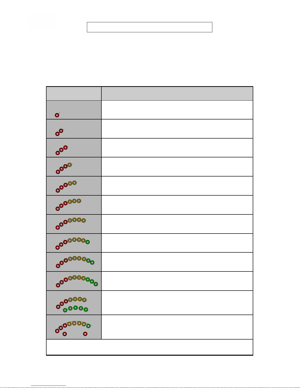
Fault Diagnosis Self-Help Guide
If a system “trip” should occur, you can find out what has caused this, by counting
the number of “Flashing” bars on the Battery Gauge. Below is a list of self-help
actions. Try to use this list before you contact your Service Agent.
Refer to the number in the list that matches the number of flashing lights and follow
the fault code diagnosis and recommended action.
NOTE: * If the programmable parameter Motor Swap, has been enabled, then left
and right-hand references in this table will need transposing.
FLASHING BAR
CODES
FAULT DIAGNOSIS and SUGGESTED ACTION
1 BAR
The Battery needs charging or there is a bad connection to the Battery.
Check connections to the Battery. If the connections are good, try
charging the Battery.
2 BAR
The Left-hand Motor * has a bad connection.
Check connections to the Left-hand Motor.
3 BAR
The Left-hand Motor * has a short circuit to a Battery connection.
Contact your Service Agent.
4 BAR
The Right-hand Motor * has a bad connection.
Check connections to the Right-hand Motor.
5 BAR
The Right-hand Motor * has a short circuit to a Battery connection.
Contact your Service Agent.
6 BAR
The wheelchair is being prevented from driving by an external signal.
Check Charger is disconnected from the Remote Controller.
7 BAR
A Joystick fault is indicated.
Make sure that the Joystick is in the central position before switching
“ON” the Control System.
8 BAR
A Control System fault is indicated.
Make sure that all connections are secure.
9 BAR
The Parking Brakes have a bad connection.
Check the Parking Brake and Motor connections are secure.
Make sure the Control System connections are secure.
10 BAR
An excessive voltage has been applied to the Control System. This is
usually caused by a poor Battery connection. Check all Battery
connections for security.
7 BAR + S
A communication fault is indicated.
Make sure that the Joystick cable is securely connected and not
damaged.
8 BAR + A
An Actuator trip is indicated.
Check Actuator wiring and connections.
NOTE: Failure to identify the fault cause from the above, should be referred to your
Service Agent.
REMOTE CONTROL FAULT DIAGNOSIS
Page 29
29
Programming the Remote Controller
The VR2 Controller is fully programmable to suit individual requirements and should
therefore be set up for the User, by a suitably qualified person using the appropriate
programming devices, at the time of hand-over.
NOTE: Programming should only be carried out by Healthcare Professionals
with in-depth knowledge of the PGDT Control Systems. Incorrect
programming could result in an unsafe set-up of the wheelchair for the User.
Neither PGDT or RMS Ltd will accept any liability, for losses or injury caused
by incorrect adjustments made, by non-suitably qualified persons, where the
system is altered from the original factory pre-set values.
Driving the Invicta Wheelchair — General
Make sure the Control System is securely
mounted and that the Joystick position is set
correctly for the User. The hand or limb to be
used to operate the Joystick, should be
supported, i.e. by the sidearm pad. Never use
the Joystick as the sole support for your hand or
arm as wheelchair movements and bumps
could affect your control. Both the Sidearm and
Remote Controller positions are adjustable to
suit individual requirements. Fig.31.
To set the correct Sidearm height, slacken
Sidearm Height Adjustment Thumb-screw,
sufficient to enable the Sidearm to be
repositioned upwards or downwards.
Retighten Thumb-screw, ensuring the screw
thread engages into the required positioning
hole.
To set the Remote Controller in the correct position, slacken both locking grub-
screws, slide Controller Stem forwards or rearwards, then secure in the required
position by retightening grub-screws sufficiently to prevent any movement.
Getting Ready to Drive your Invicta
Operate the “ON/OFF” switch. The battery gauge will blink, then remain “ON”
after a second.
Check that the maximum speed control is set to a level which suits you.
Push the Joystick to control the speed and direction in which you want the
wheelchair to travel.
NOTE: If you push the Joystick before, or just after, you switch the Control
System “ON”, the battery gauge will ripple up and down and the wheelchair
will not be allowed to move. You must release the Joystick to resume normal
operation.
If you do not release the Joystick within five seconds, the wheelchair will not
be able to move, even if release the Joystick and push it again. The battery
gauge will then flash rapidly.
You can re-set this condition, by switching the Control System “OFF” and
then back “ON” again.
If the battery gauge continues to flash rapidly, this means that the VR2 has
detected a problem somewhere in the wheelchair’s electrical system. Refer to
the Self-Help information on page 28.
Fig.31
Remote Controller
Stem Locking
Grub-screws
Use 3mm Hex Key
Sidearm Height
Adjustment
Thumb-screw
Page 30

30
Driving Technique
The Control System interprets your Joystick movements and produces appropriate
movements of your wheelchair. You will need very little concentration to control the
wheelchair, which is especially useful if you are inexperienced. Normal practice is to
point the Joystick in the direction you want to go and the wheelchair will “home-in”
on the direction the Joystick is pushed.
The further you push the Joystick away from the rest position, the faster the
wheelchair will go. Releasing the Joystick will stop the wheelchair. The intelligent
Speed Control System minimizes the effects of slopes and different types of terrain.
It is recommended that the new User is allowed, with supervision, to practice
manoeuvring in an area where there are no other people, pets or obstacles.
There are always risks and hazards attached to driving a powered wheelchair.
The risks however, can be reduced considerably, by being aware of what may
become a hazard and taking alternative measures to avoid this.
Here are some examples:-
The maximum obstacle climbing height is 50mm, therefore, care should be taken
especially when driving outdoors. Look for dropped curbs and signs indicating
wheelchair access.
Traversing slopes should be avoided wherever possible, but should it become
necessary, be aware that when driving across dropped curbs or driveways for
example, the angles can vary considerably which could have an affect on the
overall lateral stability of the wheelchair and occupant. NEVER park your
wheelchair transversely across a slope.
Avoid slopes or ramps over 12 degrees, as above this could affect the dynamic
stability of the wheelchair. NEVER attempt to negotiate steps or stairs.
Do not drive your wheelchair in places or on surfaces where a loss of wheel grip
could occur, i.e. grassy slopes, snow or ice covered surfaces.
Avoid causing serious damage to your wheelchair by impacting objects at speed
with the front Castor Wheels and/or Footrests.
Care must always be taken when using the wheelchair indoors or when
manoeuvring in confined spaces. For example, the speed setting should be
reduced to a level which the driver is comfortable with. See Speed Profile
Buttons page 27. REMEMBER one indicator light displayed is the lowest speed
range, with five indicator lights displayed being the fastest speed range.
Do not drive your wheelchair if the Control System shows any signs of not
behaving as it normally does. i.e. In the event of the wheelchair moving in an
unexpected way, RELEASE the JOYSTICK, this will stop the wheelchair under
any circumstances.
NOTE: The Manual Parking Brakes should never be used as a method of
slowing down or stopping a moving wheelchair.
Familiarise yourself as soon as possible, with your needs regarding transferring
and toileting.
Users of the Invicta IPC-T, (Tilt-in-Space model), should also be aware of the
following safety feature:-
Whilst this model is able to offer 40° of powered centre of gravity Tilt-in-Space, to
safeguard the rearward stability and assist with safer visibility when manoeuvring,
the wheelchair Control System has an inbuilt inhibitor, which prevents the
wheelchair from being driven, if the Seat Unit exceeds 15°of tilt. Therefore if you
are using the wheelchair in a tilted position and wish to move to another location,
it may be necessary for the Seat Unit to be lowered before being able to move.
Page 31

31
Your powered wheelchair is designed for minimum maintenance. However, like any
motorized vehicle, it will require routine checks and maintenance. To ensure your
Invicta wheelchair continues for many years of trouble-free operation, it is
recommended you follow the maintenance checks as scheduled below:-
WHEELCHAIR MAINTENANCE
Component Activity Daily Monthly 6
Monthly
“Drive/
Freewheel”
Selector Lever
Ensure correct operation by checking that Drive
Wheels are locked, with Lever in the forward
“Drive” position. Refer to Fig.2, page 12.
With the
Controller
turned “OFF”,
perform a
Joystick check.
Ensure the Joystick is not bent or damaged and
that it returns to its central position when released.
Visually inspect the rubber gaiter around the base
of the Joystick for wear or damage. Do not
attempt to repair it, contact your service agent if
replacement required.
Controller
Harnesses.
Visually inspect the Make sure they have no
impact damage, cuts, frays or exposed wires.
Controller
Security
Ensure all parts of the Power Controller are
securely fastened to your wheelchair
Battery
condition
Check the Battery condition meter on the
Controller to determine if Batteries require
charging. Refer to Figs.27a, b and c page 24.
Component
Security
Confirm security of Sidearms, Footrest Hangers
and Footplates. Also correct adjustment of the
Lap Belt and any positioning Harness or Foot
Control devices when fitted.
Cables Inspect cable connections for security.
Tyres Your Invicta wheelchair is supplied with puncture-
proof tyres as standard, however, where by
special request, your wheelchair has been
supplied with pneumatic tyres, the pressures
should be checked and maintained at between
30–35 psi. Also check your tyres for wear and
Damage. Contact your service agent if any
replacements are required.
Brakes Check the operation of the electro-magnetic
Brakes. This test should be carried out on a level
surface with at least one metre (3 feet) of
clearance around the wheelchair. To test the
Brakes (your wheelchair may move slightly when
performing this test):Switch “ON” the Power Controller and reduce the
speed and response setting to minimum, by use
of the “Speed Profile Decrease Button” Figs.30a
and 30b page 26
1. After one second, check the battery condition
meter remains in the good range Fig. 27a
2. Release both manual Parking Brakes.
3. Slowly push the Joystick forward until you hear
the electro-magnetic Brakes “Click”, then
immediately release the Joystick. You must be
able to hear each Brake operate within a
second or so of releasing the Joystick. Repeat
this check with the Joystick in reverse, left and
right positions. [Cont]
Page 32

Component Activity Daily Monthly 6
Monthly
Upholstery Inspect for wear or damage as this can cause
injury or discomfort to the user. Contact your
service agent if replacements are required.
The standard upholstery can be washed using
liberal amounts of warm soapy water with a little
disinfectant added, or car type upholstery
cleaner. Ensure the upholstery is thoroughly dry
before using the wheelchair.
Tension
Adjustable
Backrest
Check for correct support and adjust as required.
For adjustments, refer to Figs.13, 14, 15 and 16,
page 18.
Manual Parking
Brakes
As the efficiency of these Brakes can be affected
by tyre wear on the rear drive wheels, check their
effectiveness and adjust as required.
Refer to Fig.32, page 33.
NOTE: Minimum tyre tread depth = 1mm
Rear Drive
Wheels
Check for security. Refer to Fig.33, page 33.
With the wheels lifted clear of the ground, Parking
Brake released and the Drive Lever set to “Free-
wheel”, (in the rearward position), ensure that the
wheels spin freely and without axial run-out.
Front Castor
Forks and
Wheels
With the wheels lifted clear of the ground, check
Castor Forks for excess movement and smooth
turning. Fig.34, page 34.
Check that the wheels spin freely and without
axial run-out.
Drive Motor
Brushes
To avoid possible damage to the Drive Motors, it
is recommended by the Motor manufacturers,
that the Brushes are removed and inspected for
wear before the end of initial 12 months use.
Refer to Figs.35 & 36, page 34
NOTE: Failure to maintain the Brushes could void
the warranty coverage on the Motors.
1st check before the
end of initial 12 Months
then
6 Monthly
thereafter.
Battery Terminal
Connections
The Main Battery Leads should be checked for
clean and secure contact with the Battery
Terminals. A thin film of petroleum jelly on the
surface of the Battery Terminals will assist with
preventing corrosion.
This will require removal of the Batteries. Refer to
pages 22 and 23.
General
Tightness of
Frame Screws
and Fixings
It is recommended that a general inspection of
the wheelchair Frame, Motors and Seat fixings
are checked for security.
The recommendations listed in these tables are suggested for average use.
For heavy users, the time values should be adjusted accordingly and allowances
made for additional stresses in various areas.
For assistance with any maintenance query on the Invicta wheelchair range, please
contact the RMS Ltd. Technical Help-line on 01634-578881.
32
Page 33
33
Manual Parking Brake Adjustment
As the efficiency of the Manual Parking
Brakes can be affected by tyre wear on
the rear drive wheels, adjustment is
made available on each Brake Mounting
Bracket. Fig.32.
NOTE: Care must be taken to maintain
correct alignment of the Brake
Mechanism, when carrying out this
adjustment, as incorrect positioning
could result in the Brake Mechanism
being ineffective, or fouling the Drive
wheel tyre.
Tools Required:-
“T” 5mm Hexagon Key.
With the Brake lever set in the fully
“OFF” (rearward) position, slacken
both screws on the Manual Brake
Mounting Clamp, just sufficiently to
enable the Brake mechanism to be re-set.
Re-position the Brake mechanism to give 19mm (¾") clearance between the
Brake Bar and the tyre. Avoid moving the Mounting Clamp from it’s original
position.
With the Brake mechanism held in this position and while ensuring the Brake
Bar is at 90° to the tyre, retighten both Brake Mounting Clamp screws, sufficiently
to prevent any movement. Repeat this procedure for the opposite side.
Apply both Parking Brakes before setting the wheelchair Drive Mode Lever to
“Free wheel” (rearward direction), then confirm that it is not possible to move the
wheelchair with only the Parking Brakes applied.
Checking security of Rear
Drive Wheels. (Fig.33)
Tools Required:-
Suitable Torque Wrench and socket with
6mm Hexagon Bit.
13mm Spanner.
Security of the Rear Drive Wheels,
should be checked at 6 monthly
intervals, (more frequently may be
required for very heavy users).
Failure to do so, could result in
premature wear of the wheel mounting
holes and motor drive flanges.
Screws should be tightened evenly
to 27Nm (20ft/lbs), whilst holding the
corresponding nuts at the rear of the
wheel with a spanner. DO NOT
OVERTIGHTEN.
Fig.32
Mounting
Bracket
Clamp
Screws
90°
Manual
Parking
Brake
Brake Bar
Drive Wheel
retaining screws
Fig.33
Page 34
34
Checking the Front Castor Forks and
Wheels
With the wheels lifted clear of the ground,
check the Castor Forks for excess
movement in the swivel bearings and for
smooth turning.
This is important—as unsmooth turning
by the Castor Wheels can seriously affect
the wheelchair steering and
manoeuvring.
Also check that the Castor Wheels spin
freely and without axial run-out. Fig.34
If there is any doubt about the
movement in either the Castor Forks
or the Wheels, contact your repairing
agent as soon as possible.
Checking the Drive Motor Brushes
It is recommended that after the first 12
months of use, the Drive Motor Brushes
should be checked by your service
agent and thereafter at 6 monthly
intervals to maintain peak Motor
performance.
Each Drive Motor is fitted with two
Brushes, however, as access to the
inner Brush Retaining Cap is limited by
the Battery Carrier Frame, inspection of
the outer Motor Brushes should give an
indication of the wear on both Brushes.
Tools Required:Flat-bladed Screwdriver,
(blade width = 4 to 6mm).
To inspect the outer Brushes, unscrew
the Brush Retaining Caps, Fig.35 and
withdraw the Brushes from their holders.
Measure the length of each Brush to
ensure that they exceed the minimum
length of 10mm. If less than 10mm
replace Brushes at this time. Fig.36
NOTE: Both Brushes must be replaced
at the same time, on each Motor.
Replacement of the inner Brushes will
require removal of the complete Motor.
Brush
Retaining Caps
Minimum Length
= 10mm
NEW
PART WORN
Fig.34
Fig.35
Fig.36
DRIVE MOTOR BRUSHES
Page 35
35
Anti-tip Devices
Height adjustable Anti-tip devices are supplied
as standard with the Invicta Powered
Wheelchair.
For normal use, it is recommended that the Antitip devices are set to the highest position, Fig.37.
This will give a ground clearance between the
jockey wheel and the floor of 40mm. In turn, this
will allow the wheelchair to be able to climb an
obstacle of up to 50mm.
To alter the Anti-tip height, pull the Spring-loaded
Locking Pin rearwards to disengage the Anti-tip
Stem. Re-set to required height and re-engage
Locking Pin.
Retaining Lap-Belt
The standard Lap Belt supplied with the Invicta
is the RMS PB002 with single “Pull-tight” plastic
buckle.
Separate the Belt at the main buckle by
depressing the locking tongue, Fig.438.
With the User seated, route each end of the Lap
Belt up and over the User’s hips and round to the
front of the User, connecting the main buckle in
the centre of their lap.
Adjustment is made by pulling the “free-end”
through the buckle to the required position.
Overall belt length can be adjusted at the Tri-slot
mountings located at each end of the Belt where
they are attached to the Seat frame.
NOTE: If it becomes necessary to change the
Backrest angle, it may also be necessary to re-position the Lap Belt Mountings,
utilising an alternative vacant hole on the Backrest Connecting Bracket. Fig.18
Fig.37
Spring-loaded
Locking Pin
Fig.38
Main Buckle
Locking Tongue
“Pull-tight”
free-end
Page 36

36
Keeping the Invicta Wheelchair Clean
The wheelchair paintwork should be cleaned on a monthly basis by wiping with a
damp cloth and mild detergent. Polishing with good quality auto wax will help to
preserve the Frame appearance.
The upholstery can be cleaned by lightly sponging using warm soapy water with a
little disinfectant added.
DO NOT USE any scrubbing agents.
DO NOT USE high-pressure cleaning devices.
DO NOT subject the electronic components to direct contact with water.
Wipe off all cleaned areas with a clean dry cloth and ensure the upholstery is
thoroughly dry before re-using the wheelchair.
The standard Lap Belt with a plastic buckle can be removed from the wheelchair
and machine washed if required. Ensure the nylon webbing is correctly threaded
through the Tri-slot mounting when re-installing.
WHEELCHAIR CLEANING
Page 37

37
End of Product Life
Although your Invicta Powered Wheelchair has been designed to provide you with a
long and trouble-free life, it is inevitable that wear, tear and continual usage will
eventually render the device unusable or beyond economical repair.
RMS Ltd, recommends that the average usable life-cycle expectancy of the Invicta
Powered Wheelchair is five years, assuming that it has been maintained according
to the manufacturer’s recommendations.
When the time comes to replace your wheelchair, please remember to dispose of
the device responsibly and recycle as many parts as possible.
Where your wheelchair has been supplied by an NHS Wheelchair Service, they, or
their Appointed Service / Repair Agent, can arrange for safe disposal.
If your wheelchair is privately owned, then it is the owners responsibility to dispose
of the device at the end of its useful life cycle, in a safe and proper manner.
Your local Council will normally be able to assist with this.
WHEELCHAIR DISPOSAL
Page 38

38
All specifications are in centimetres and kilograms unless otherwise stated and are
correct at the time of publication.
The manufacturer reserves the right to change any specifications without notice
where they are considered necessary to improve the product quality or any safety
aspect.
TECHNICAL DATA
INVICTA IPC-S
Standard Model
Maximum User Weight
Non-Transport Use
100Kg
Maximum User Weight
For Transportation
50Kg
Total Weight 80Kg
Weight of Chassis
c/w with Batteries
57Kg
Weight of Seat Unit
without Footrest Hangers
18.3Kg
Overall Length
with standard Footrests
95cm
Overall Length
without Footrests
72cm
Overall Length
with Elevating Legrests
raised to max.
TBA
Overall Width 62cm
Overall Height
Without Headrest
81cm
Backrest Height 35cm
Seat Height
to Seat Board
46cm
Turning Radius
with Footrests
60cm
Ground Clearance 7cm
Maximum Obstacle
Climbing
5cm
Dynamic Stability 10°
Front Castor Wheels
with puncture-proof tyres
unless otherwise requested
200 x 50mm
Rear Drive Wheels
with puncture-proof tyres
unless otherwise requested
320 x 60mm
INVICTA IPC-T
Tilt-in-Space Model
Maximum User Weight
Non-Transport Use
100Kg
Maximum User Weight
For Transportation
50Kg
Total Weight 85Kg
Weight of Chassis
c/w Batteries
57Kg
Weight of Seat Unit
Incl. Tilt Actuator
without Footrest Hangers
25.8Kg
Overall Length
with standard Footrests
95cm
Overall Length
without Footrests
72cm
Overall Length
with Elevating Legrests
raised to max.
TBA
Overall Width 62cm
Overall Height
Without Headrest
81cm
Backrest Height 35cm
Seat Height
to Seat Board
46cm
Turning Radius
with Footrests
60cm
Ground Clearance 7cm
Maximum Obstacle
Climbing
5cm
Dynamic Stability with
Seat in fully lowered
(upright) position
10°
Front Castor Wheels
with puncture-proof tyres
unless otherwise requested
200 x 50mm
Rear Drive Wheels
with puncture-proof tyres
unless otherwise requested
320 x 60mm
Page 39

39
INVICTA IPC-S
Standard Model
Seat Width
30cm
Std. Seat Depth
29cm
adjustable
Seat Width
35.5cm
Std. Seat Depth
34.5cm
adjustable
Seat Width
41cm
Std. Seat Depth
39.5cm
adjustable
Seat Depth adjustable from 24cm and 42cm
in 25mm increments.
Backrest Angle 90° - 135°
in 7.5° increments
N/A N/A
Sidearm Height
Adjustable
220mm—340mm
From Seat Board
Sidearm Length 30cm
Sidearm Width 8cm tapering
Lower Leg Length
To Std. Seat Cushion
30cm - 40cm
Batteries x 2
MK 8GU1H
12V - 31Ah Gel.
Drive Range 15 Miles
Drive Motors 24v DC - 450W
4600rpm
Maximum Speed 4Mph
6Km/h
Battery Charger
115-230v
5 Amp Off-Board
28.8V Charging V
Control System
PGDT VR-2
Controller
JSM
Control System
PGDT VR-2
Power Module
VR2 60
Seat and Backrest
Frames
Mild Steel
Finished in
Matt Black
Powder Coating
Chassis Frame Aluminium
finished in
Silver Metallic
Powder Coating
INVICTA IPC-T
Tilt-in-Space Model
Seat Width
30cm
Std. Seat Depth
29cm
adjustable
Seat Width
35.5cm
Std. Seat Depth
34.5cm
adjustable
Seat Width
41cm
Std. Seat Depth
39.5cm
adjustable
Seat Depth adjustable from 24cm and 42cm
in 25mm increments.
Backrest Angle 90° - 135°
in 7.5° increments
Seat Angle
Tilt-in-Space
0° - 40°
Sidearm Height
Adjustable
220mm—340mm
From Seat Board
Sidearm Length 30cm
Sidearm Width 8cm tapering
Lower Leg Length
To Std. Seat Cushion
30cm - 40cm
Batteries x 2
MK 8GU1H
12V - 31Ah Gel.
Drive Range 15 Miles
Drive Motors 24v DC - 450W
4600rpm
Maximum Speed 4Mph
6Km/h
Battery Charger
115-230v
5 Amp Off-Board
28.8V Charging V
Control System
PGDT VR-2
Controller
JSM-A
Control System
PGDT VR-2
Power Module
VR2 60 (A1)
Seat and Backrest
Frames
Mild Steel
Finished in
Matt Black
Powder Coating
Chassis Frame Aluminium
finished in
Silver Metallic
Powder Coating
Page 40

40
WHEELCHAIR ACCESSORIES
Accessory List
A range of accessories are also available for use with the Invicta Powered
Wheelchair, these include:-
Acta-Back Contoured Backrests
with compatible
Lateral Support Brackets and Pads.
Headrests with optional Brackets.
Padded Pelvic Belts
Harnesses — Butterfly
Sternum
Shoulder
Dynamic
Alternative Remote Controllers
Attendant Controller
Mid-line Controller mounted to
Clear Plastic tray
Attendant Hand-held Cut-out Button
Contoured Tray
Elevating Legrests
Oxygen Cylinder Carrier
Calf Straps
Foot Control Devices
Footboards
Please call the RMS Sales or Technical Help-line on 01634-578881 for further
information on any of the above accessories.
Page 41

41
USER NOTES
Page 42

USER NOTES
Page 43

USER NOTES
Page 44

Powered Wheelchairs
MEDWAY HOUSE
277 Gillingham Road, Gillingham, Kent, ME7 4QX
Tel: 01634 578881 Fax: 01634 581456
Email address: [email protected]
 Loading...