


1
Installation & User Guide
Unicable™ II Programmer
IDLU-PROG01-OOOOO-OPP
Item: 5273

2

3
Thank you for purchasing Inverto’s advanced Unicable II programmer. Before installing and using
the programmer, please read the following instructions and recommendations. We suggest that
you keep this guide for future use.
1. Warranty
This Unicable II programmer is designed for use with satellite television installations. The warranty
does not apply for products used for other purposes other than those specified herein. The user/
installer shall be responsible for any damage incurred as a result of not using the product according to the instructions in this manual.
2. Overview
Connections
■
ODU (LNB/Switch) Connect the Unicable II ODU device
(LNB or Multiswitch output port)
■
Receiver Loop-through
(DC Pass, RF Loop)
■
DC In Connect 12V AC/DC adapter
■
PC Connect USB cable to PC
Buttons
■
Transmit/Validate - Short press (<1s) transmits a stored configuration to the ODU
■
Device Configuration - Long press (>1s) reads the configuration from ODU and com pares with a configuration stored in the programmer.
If both configurations are identical the Status LED will turn green
(only supported for ODU products: Item 5235, 5156, 5294)
LEDs
■
Power - Red if the programmer is powered from USB
- Orange if the programmer is powered from 12V
■
Status - Yellow (blinking) while the programmer is busy
- Green if the configuration stored in programmer and
configuration read from the ODU are identical

4
3. Installation
Before connecting the Unicable II Programmer device to the PC, please follow the below steps for
installation of the PC software and driver.
■
Download the Unicable_II_Programmer.msi software from: http://www.inverto.tv/support
to your PC
■
Start the installation by double click on Unicable_II_Programmer.msi
■
Follow the instruction on the screen
■
After installation you will find an Unicable II Programmer icon on the desktop.
After installing the PC software, connect the Unicable II Programmer to the PC using the USB
cable.
Window will ask for the driver, if the programmer is used for the first time on this PC. Select to
manually install the driver and select it from the program folder of the PC software (for example:
C:\Program Files\Inverto\Unicable II Programmer\driver).
If Windows does not ask for the driver, please go to the Device Manager (Control Panel -> System
-> Device Manager) and install the driver manually.
Figure 1: Driver installation
Note: If you are facing any problems during the installation, please refer to the troubleshooting.

5
4. Connect the Programmer & start the PC
Software
■
Connect the 12V AC/DC adapter to the power input of the programmer
■
Connect the programmer to the PC using the USB cable
■
Start the PC software with a double click on the Unicable II Programmer icon on the
desktop
If the programmer was not detected you will see a notification at startup. In this case please make
sure that the programmer is powered, connected correctly to the PC and that the driver has been
installed, then restart the Unicable II Programmer PC software.
5. Create/Edit a configuration for a Unicable II
Switch/LNB
There are two ways to change the configuration of an Unicable II device that is connected to the
Unicable II Programmer:
Create a new Configuration
Select “Task” -> “Create a configuration” if you want to start a new configuration
from scratch
Edit an existing configuration
Select “Task” -> “Edit a configuration” and then select whether you want to load a
previous configuration from a file, to load the current configuration of the connected Unicable II device or to load the configuration that is currently stored in the Unicable II Programmer
Depending on your Unicable II device you can choose between different configurations in the
setup tab:
Unicable
The output of the device will be Unicable mode with user bands accessible according to EN50494
and/or EN50607 standard (see 6).
Unicable (Independent Output)
This option is available for switches with two outputs. Each output can have an independent
Unicable configuration. For example you can setup 2 x 16 user bands and the outputs behave
like two independent Unicable II Switches with 16 user bands each.
Unicable (Shared Output)
This option is available for switches with two outputs. In this setup you can access the configured
user bands from both ports. This option is useful to split the Unicable output to two different
locations without using a splitter.
Unicable + Legacy
This option is available for switches with two outputs. One output will be Unicable, while the
other output is working in Legacy (Universal) mode.
Static
The output of the device is static, means that you can configure a fixed transponder – user band
mapping (see 7).

6
Static + Legacy
This option is available for switches with two outputs. On output will work in static mode (see 7),
while the other output is working in Legacy (Universal) mode.
Satellite Position
It is possible to connect (chain) the outputs of multiple LNBs or multiswitches together with RF
combiners and setup each device to provide the signal from a different satellite position.
For example you can configure one LNB for satellite A and a second one for satellite B. If the STB
now requests a channel from satellite A the first LNB will enable the user band while the seconds
LNB will disable the user band. If the STB requests a channel from satellite B, the first LNB will
deactivate the user band and the seconds LNB will provide the user band.
Quattro LNB Input (1 Satellite)
The Unicable II switch will be setup to receive a Quattro LNB signal on its inputs.
It is possible connect (chain) the outputs of multiple switches together with RF combiners and
setup each of the switches to provide the signal from a different satellite position.
For example you can configure one switch for satellite A and a second one for satellite B. If the
STB now requests a channel from satellite A the first switch will enable the user band while the
seconds switch will disable the user band. If the STB requests a channel from satellite B, the first
switch will deactivate the user band and the seconds switch will provide the user band.
Wideband LNB input (2 Satellites)
The Unicable II switch will be setup to receive wideband signals on its inputs from 2 different
satellite positions.
It is also possible connect (chain) the outputs of two switches together with a RF combiner and
setup one switch to provide the signal from satellite A and B and the seconds one from satellite
C and D. It means that if a STB request a channel from satellite A or B, the first switch will enable
the user band and the seconds switch will disable the user band. If the STB then request a channel
from satellite C or D, the first switch will deactivate the user band and the seconds switch will
provide the user band.
Additional options on certain devices:
Legacy at Startup
By activating this option you can configure the device to output a legacy (Universal) signal at
startup. After sending an Unicable command the device will switch to Unicable mode.
This option is useful for LNBs if you want to use an antenna meter that does not support Unicable
standards to align the dish.
Unicable II UB numbering
If you activate this option you can change the number of the user band configured in EN50607,
in case you don’t want to have a continuous numbering.

7
6. Unicable
Depending on the device it is possible configure up to 32 user bands for Unicable.
■
Click on the arrow button near to the output of the device to select how many user band you
want to use on this output.
■
For each user band you can configure
Standard
Select whether the user band should be accessible as EN50494, EN50607 or bothEN50494+EN50607
Unicable I / Unicable II
User band number for Unicable I (EN50494) and Unicable II (EN50607)
Frequency
Enter the IF frequency for the user band (the IF frequency may not overlap)
Bandwidth
Select the bandwidth for the user band
PIN
Enter the PIN code to be used for this user band
Power
On some devices you have the option to adjust the user band RF power level

8
7. Static
Depending on the device it is possible to configure up to 32 static user bands
■
Click on the arrow button near to the output of the device to select how many static user
bands you want to use on this output.
■
For each user band you can configure
Frequency
Enter the IF Frequency
Transponder
Select the frequency of the transponder that should be mapped to the IF frequency
Polarization
Select the polarization of the transponder
Bandwidth
Select the bandwidth of the user band (must be equal or bigger than the bandwidth of the
selected transponder)
Power
On some devices you have the option to adjust the user band RF power level

9
8. Upload the configuration to the Unicable II
Switch/LNB
After entering your configuration you can upload it to the Unicable II device by pressing the
button “Send to ODU”.
You can also store the configuration inside the programmer. This allows updating Unicable II
devices without having a PC connected to the programmer by pressing the update button on
the programmer.
For further use you can also save the current configuration on your PC, by clicking on “Save to
File”.
9. Troubleshooting
No communication between the programmer and the PC software
In case the programmer and the software are installed properly, but the software does not detect
the programmer, you might see the following message.

10
Before you proceed, please check:
1. Is the USB cable connected to the PC and the programmer
2. Is the programmer LED - close the USB plug - on
3. Open the device manager and check that the programmer is listed as “Microchip Custom
USB device”
To fix this problem, the software must be started in compatibility mode.
This is an option that is available in the file properties. Select the desktop shortcut (or the EXE file
itself) by right click and click “properties”
In the next step you select to run this program in WinXP SP3 compatibility mode and apply the
settings.
Now the software is ready to be used.
11
Driver can’t be installed (Win8.1 64bit or newer)
The drivers are currently not signed for Windows 8.1 or newer. During the driver installation you
will be notified:
“Windows found driver software for your device but encountered an error while
attempting to install it. The hash for the file is not present in the specified catalog
file. The file is likely corrupt or the victim of tampering.”
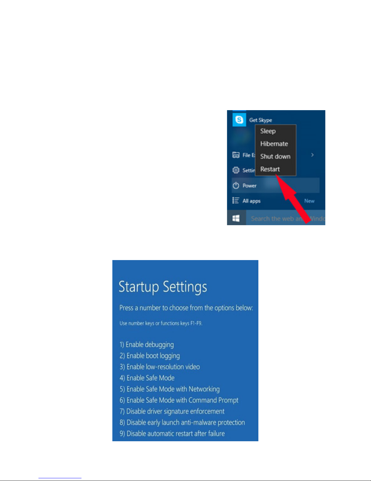
In this case you need to disable the windows driver signature enforcement; this option can be
setup by an advanced reboot.
To access this boot menu, proceed to the windows power
menu, open the menu and hold the shift key while selecting
“Restart”. Once the computer has restarted you are in the
boot menu.
Choose Troubleshoot -> Advanced Options -> Startup Settings and then confirm the restart.
Finally you are able to access the startup settings and select to disable the driver signature enforcement by pressing F7 on your keyboard.
Now you can continue to install the drivers.

12
10. Technical parameters
Interfaces: 1x Satellite IF, F-type
1x Satellite IF loop-through out, F-type
1x USB (Type-B)
Loop-through loss: 1dB max.
Control protocols: DiSEqC™ commands extension according to CENELEC EN50494
and/or EN50607, DiSEqC2.0.
Display and keys:
- Activity LED Yellow blinking: Communication activity between ODU and Pro
grammer
Green: Configuration files in ODU and Programmer are identical
- Power LED Red: The Programmer is powered over the USB connection
Orange: The Programmer is powered over the 12V DC input
- Button Short press: Transmit a configuration file stored in the
Programmer to the ODU device
Long press: Download the configuration file of the ODU and
compare to a file stored in the Programmer
Power consumption:
- Programmer only: 5VDC, 50mA (can be powered over the USB interface)
- ODU power: 13V-18V, 600mA max. - powering and programming of an ODU
device requires use of the supplied AC/DC adapter.
Dimensions: 107mm x 77mm x 30 (W x D x H)
AC/DC adapter: Input voltage: 100-240VAC, 50/60Hz, 0.8A max.
Output voltage: 12VDC
Output current: 2A
Short circuit protection: Yes
Low Voltage Directive (2014/35/EU)
Electromagnetic Compatibility Directive (2014/30/EU)
Eco-Design Directive (2009/125/EC)

11.Safety
This product is for indoor use in moderate climates only.
This product contains no user serviceable parts. The unit should only be opened or repaired by
qualified service personnel. The supplied AC/DC power adapter must be used to power this
product. If the power cord becomes damaged, it must be replaced. Always refer to qualified
personnel.
Install the product so the AC/DC power adapter can be unplugged from power socket immediately, in the event of a problem.
The unit should not be placed near sources of open flame. No open flame sources, such as candles, should be placed on the unit.
Make sure the local electricity network corresponds to the operating voltage of the AC/DC adaptor. If the products gets into contact with liquid it must be disconnected from the main power.
When disconnecting the product don’t pull the cable but the plug to prevent damage of the
cable (wobbly plugs and outlets result in fire risk).
The product shall be serviced by qualified experts only.
11. Disposal
Following relevant EU directives, this device shall not be disposed of together with municipal
waste. Use local waste collection and recycling systems to dispose wore out products.
*
DiSEqC™ is a registered trademark of Eutelsat
*
For purpose of brevity, some product descriptions in this sheet remain at platform level and may not be referred to
as detailed data-sheets of the products. Inverto Digital Labs reserves the right to amend, omit or add products.

14
Notes
........................................................................
........................................................................
........................................................................
........................................................................
........................................................................
........................................................................
........................................................................
........................................................................
........................................................................
........................................................................
........................................................................
........................................................................
........................................................................
........................................................................
........................................................................
........................................................................
........................................................................
........................................................................
........................................................................
........................................................................
........................................................................
........................................................................
........................................................................
........................................................................
........................................................................
........................................................................
........................................................................
........................................................................
........................................................................
........................................................................
........................................................................
........................................................................
........................................................................
........................................................................
........................................................................
........................................................................
........................................................................
........................................................................
........................................................................
........................................................................
........................................................................
........................................................................
........................................................................

15

V300316
FTA Communication Technologies S.á r.l.
18 Duchscherstrooss, L-6868 Wecker, Luxembourg
Tel: +352 264 367 1, Fax: +352 264 313 68
info@inverto.tv www.inverto.tv
 Loading...