

Inverto IDLV-3440DM User Manual
IDLV-3440DM
Professional 4-Channel DVB Receiver and
Transmodulator


IDLV-3440DM
Professional 4-Channel
DVB Receiver and
Transmodulator
User Manual
En


Table of Contents
Notices 2
Before using the device 3
Overview 4
Front panel and Rear panel instructions 5
Operation instructions via Front Panel 6
Web Control 13
Installation 25
Accessories 25
Technical Specications 26
Safety 27
Warrenty, service and support 30
En
1

Notices
COPYRIGHT (Copyright © 2015 Inverto Digital Labs )
Not to be copied, used or translated in part or whole without Inverto prior consent in writing except approval of
ownership of copyright and copyright law.
WARRANT Y
This warranty does not cover parts which may become defective due to misuse of the information contained in this
manual. Read this manual carefully and make sure you understand the instructions provided. For your safety, be
aware of the following precautions.
WARNING! IMPORTANT SAFETY INSTRUCTIONS
CAUTION: TO REDUCE THE RISK OF ELECTRIC SHOCK, DO NOT REMOVE COVER (OR BACK). NO
WARNING
• To reduce the risk of re or electric shock, do not expose this apparatus to rain or moisture.
• To avoid explosion danger, do not dispose of batteries in an open re.
IMPORTANT INFORMATION
Please retain the original packaging, should it be necessary at some stage to return the unit.
Disposal of Old Electrical and Electronic Equipment (Applicable in the European Union and other European
countries with separate collection systems)
This symbol on the product or on its packaging indicates that this product shall not be treated as household waste.
Instead it shall be handed over to the applicable collection point for the recycling of electrical and electronic
equipment. By ensuring this product is disposed of correctly, you will help prevent potential negative consequences
for the environment and human health, which could otherwise be caused by inappropriate waste handling of this
product. The recycling of materials will help to conserve natural resources. For more detailed information about
recycling of this product, please contact your local Civic Ofce, your household waste disposal service, or the shop
where you purchased the product.
USER SERVICEABLE PARTS INSIDE. REFER SERVICING TO QUALIFIED SERVICE PERSONNEL.
CE MARK FOR EUROPEAN HARMONISED STANDARDS
The CE mark which is attached to these products means it conforms to EMC Directive (89/336/EEC) and
Low Voltage Directive (73/23/EEC).
COPYRIGHTS
Television programmes, movies, video tapes, discs, and other materials may be copyrighted. Unauthorized
recording of copyrighted material may be against the copyright laws in your region. Also, use of this product with
cable television transmissions may require authorization from the cable television operator or transmitter/owner.
VENTILATION
• Do not expose the product to high temperatures, such as placing it on top of other product that produce
heat or in places exposed to direct sunlight or spot lights.
• The ventilation slots on top of the product must be left uncovered to allow proper airow into the unit.
• Do not stand the product on soft furnishings or carpets.
• Do not stack electronic equipments on top of the product.
• Do not place the product in a location subject to extreme changes in temperature. The temperature
gradient should be less than 10 degrees C/hour.
• Place the product in a location with adequate ventilation to prevent the build-up of heat inside the product.
The minimum ventilation space around the unit should be 7 cm. The ventilation should not be impeded by covering
the ventilation openings with items, such as newspapers, table cloth, curtains, etc.
POWER SOURCES
• The product is not disconnected from the AC power source (mains) as long as it is connected to the power
outlet or wall socket, even if the product is turned off.
• If the product will not be used for a long period of time, disconnect it from the AC power outlet or wall socket.
2

Before Using the device
Thank you for purchasing the IDLV-3440DM Professional HDTV Integrated Receiver Decoder. This User Manual is
written for operators/users of the IDLV-3440DM to assist in installation and operation. Please read this user manual
carefully before installation and use of the devic.
FOR YOUR SAFE TY
This equipment is provided with a protective earthing ground incorporated in the power cord. The main plug shall
only be inserted in a socket outlet provided with a protective earth contact. Any interruption of the protective
conductor, inside or outside the device, is likely to make the device dangerous. Do not remove the covers of this
equipment. Hazardous voltages are present within this equipment and may be exposed if the covers are removed.
Only Inverto trained and approved service engineers are permitted to service this equipment.
The supplied AC power cable must be used to power the device. If the power cord becomes damaged it must be
replaced. No operator serviceable parts inside. Refer servicing to Inverto trained and approved service engineers.
For the correct and safe use of the device, it is essential that both operating and servicing personnel follow
generally accepted safety procedures in addition to the safety precautions specied in this manual. Whenever it
is likely that safety protection is impaired, the device must be made in-operative and secured against unintended
operation. The appropriate servicing authority must be informed. For example, safety is likely to be impaired if the
device fails to perform the intended measurements or shows visible damage.
WARNINGS
• The mounting environment should be relatively dust free, free of excessive vibration and the ambient
temperature between 0C° to 40C°. Relative humidity of 20% to 80% (non-condensed) is recommended.
• Avoid direct contact with water.
• Never place the equipment in direct sunlight.
• The outside of the equipment may be cleaned using a lightly dampened cloth. Do not use any cleaning
liquids containing alcohol, methylated spirit or ammonia etc.
• For continued protection against re hazard, replace line fused only with same type.
• Air intake for cooling is achieved via holes at the side of the device and the fans inside. The air ow should
not be obstructed. Therefore, the device has to be placed on a at surface, leaving some space at the
sides of the device.
• When in operation, the internal temperature should not exceed the limit of 70C°.
En
3
Overview
IDLV-3440DM integrates 4 DVB Receiver and Transmodulator in one 1U 19” chassis. It provides operators an ideal
DTV headend setup solution by combining multi-channel receiving, descrambling, remultiplexing and DVB QAM/
COFDM modulation and TS over IP operations together in one single unit. Equipped with 4 independent tuner front
ends with various factory options for DVB-T/T2, DVB-S2/S, DVB-C, DTMB, ISDB-T and ATSC types, standard ASI
and TS/IP I/O interfaces, IDLV-3440DM ensures compatibility with all types of transmission media.
The standard four PCMCIA common interface slots on the rear panel support the most popular CI CAMs in the
market to de-crypt multiple pay TV services. Being a highly integrated, compact size device offering wide exibility
in system conguration and reliable functionality, makes the IDLV-3440DM one of the most competitive product in
the head-end market.
CHARAC TERISTICS
• 4x Tuner Input, Supports variety of input options DVB-T2/T/S2/S/C/DTMB/ATSC/ISDB-T)
• Supports DVB-S2 Input Stream Identier (ISI, optional) and DVB-T2 Multi PLP and SFN MIP pass through
• 4 x DVB QAM/COFDM Modulation, 4 x RF Channel Output (Adjacent channel)
• Built-in TS re-multiplexer receives from ASI, CI Slot1 to CI Slot4 and TS/IP inputs
• 4×DVB-CI Slots, multi-program decryption, BISS-1 and BISS-E decryption
• ASI output the transport stream from CI Slot1 to CI Slot4 or BISS decryption
• 1xchannel full duplex TS over IP or 5xchannels IP out without IP input
• Remote Control and Monitoring by SNMP v2, HTTP WEB and Proprietary PC software
• On Site software update through IP or USB
• RSSI, received signal strength, Eb/N0, C/N and BER monitoring
• Redundant power supply
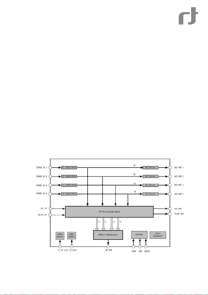
BLOCK DIAGRA M
The diagram below shows a top level architecture and functional block diagram of the IDLV-3440DM Platform:
4
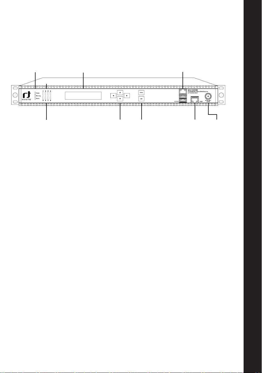
Front panel and Rear panel Instructions
FR ON T PA NEL
LED POWER
LED WARNING
LED ALARM
LED TUNER LOCK
MODULATOR STATUS
LED POWER When turned on, the Green LED indicates that power is available.
When turned off, the power is not available or failed
LED WARNING Led On
Led Off
LED Alarm LED ON: Alarm or alarms have been triggered, For alarm description,
please refer to details in the table 10.
LED OFF: The equipment works properly
VFD DISPLAY
OPERATION BUTTONS
CONTROL
TS/IP
RF MONITOR
-20dB
En
LED TUNER LOCK LED ON: Tuner input is locked
LED OFF: Tuner is un- locked
VFD Display Display menus, submenus and their parameters
Cursor Keys UP, DOWN, LEFT, RIGHT. Used to navigate through the menu system
ENTER key Conrm a selection then return to previous menu
EXIT Key Exit and return to previous menu
Control RJ-45 Ethernet port for equipment control and monitoring
Control - USB USB port for rmware upgrade
TS/IP RJ-45 TS over IP Ethernet port
RF Monitor To monitor the modulated signal
5
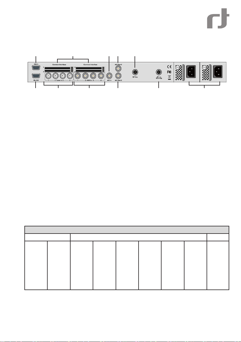
REAR PANEL
2 4
1 3
1 RS-232 Reserved for factory use
2 Alarm Alarm relay interface
3 Tuner In-1/4 4 Tuner Inputs
4 Common Interface 4 Common Interfaces
5 ASI Out-1/4 4 pass through ASI output
6 ASI In ASI input
7 ASI Out-5 Main ASI output
8 ASI Out-6 Backup ASI output port
9 RF Out Main RF output port
10 RF In backup RF backup signal input when the built-in modulator is down
11 Power Supply Input Dual AC power supply
5
6
9
7
8
10
11
Operation instructions via Front Panel
With the keypad and display panel on the front panel, Users can congure the device locally.
OVERVIE W OF MENU
Power on the device and wait for initialization complete, the Local IP address will be displayed on the VFD panel.
Press{ENTER}to get into the main menu.
Main menu
Status Conguration System
TS/IP
Status
I/O Status
6
(Full
Duplex/
Multiple
Output)
Slave
board
Remux
TS/IP
(Mode:
Multiple
Output/
Full
Duplex)
COFDM
/QAMRFSetting
ASI
Output
DESC RIPTION OF MENU
The main menu items can be selected with the keypad. By pressing the [Enter], the user navigates to the
submenus, which are selected in the same manner.
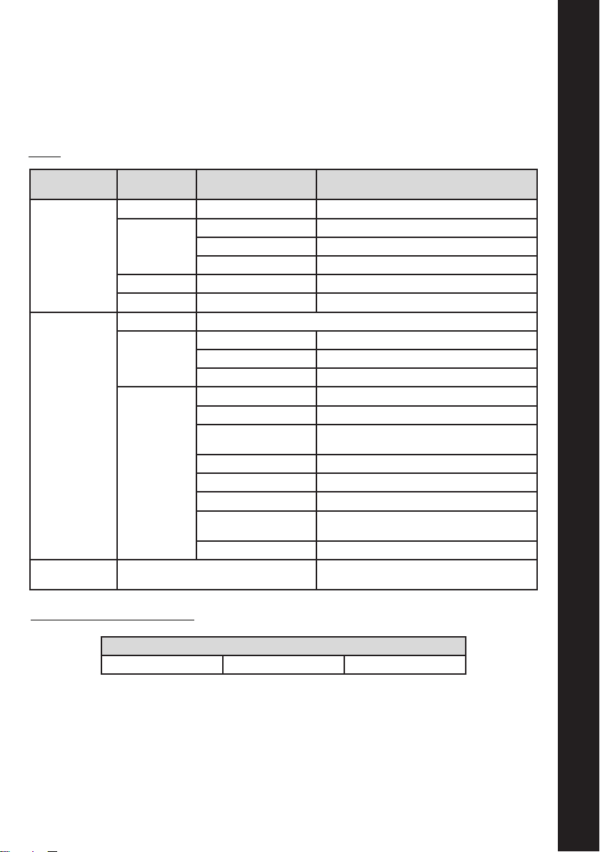
Status:
En
Submenu
Layer 1
I/O Status
TS/IP Status
(Full Duplex)
TS/IP Status
(Multiple Output)
Submenu
Layer 2
Tuner Status Tuner 1/2/3/4 Lock/Unlock
Input Bit rate
Output Bit rate Remux Bit rate Valid bit rate and total bit rate
Modulator Moulator 1/2/3/4 Valid bit rate and total bit rate
Link Status Display IP link status:10M/100M/1000M/Disconnect
Gigabit Output
Status
Gigabit Input
Status
Parameters Description
Tuner 1/2/3/4 Valid bit rate and total bit rate
ASI Valid bit rate and total bit rate
IP Valid bit rate and total bit rate
UDP Packets/s Display IP out UDP packet rate
Column FEC Pkts/s Display IP out column FEC packet rate
Row FEC Pkts/s Display IP out row FEC packet rate
IP Input Status Display IP in lock/unlock status
IP Input Protocol Display the protocol of IP input
Column/Row FEC Display the mode of column FEC and row
Pkts per UDP Frame Display the packets per UDP frame
Received TS Frames Display the received TS frames
Fixed RTP Frames Display the xed RTP frames
FEC Counter Display the FEC packets that has been
FEC Counter Reset Reset the FEC packets counter
Link Status
FEC
received
Display IP link Status:
10M/100M/1000M/Disconnect
Conguration – Slave Board Setup:
Tuner 1/2/3/4 CI 1/2/3/4 BISS 1/2/3/4
Slave Board Setup
7
 Loading...