

Inverto IDL-5000HD User Manual
1EnIDL5000HD-print.fh10 1/18/06 12:53 PM Page 1
Digital Satellite Receiver
High Definition TV
Iredeto embedded
IDL-5000HD
C M Y CM MY CY CMY K
Composite
Trade Mark of the DVB Digital Video Broadcasting Project (1991 to 1996)
Declaration of Conformity No. 3338, 18th August, 2004

1EnIDL5000HD-print.fh10 1/18/06 12:53 PM Page 2
Trademark Acknowledgment and license notice
Manufactured under license from Dolby Laboratories.
"Dolby", "Pro Logic", and the double-D symbol are Trademarks of Dolby Laboratories.
Safety Always Comes First
This IDL5000HD HD Digital Receiver is manufactured according to international safety standards. In order
to obtain the best operation results, please read the entire manual, as you will be instructed on how to
handle the equipment carefully and safely. While installing, if you discover equipment failure or if you have
doubts about the installation, handling, or safety of the STB please contact your Service Provider.
A Few Words about Cautions:
To Reduce the RISK of Electrical Shock, DO NOT REMOVE cover or back.
No User-serviceable parts inside. Refer to Qualified Service Personel.
No naked flame sources, such as lighted candles, should be placed on
the apparatus.
This symbol is intended to alert the user to the presence of non-insulated
dangerous voltage with the product’s enclosure that may be of significant
magnitude to constitute the risk of electric shock to persons.
This symbol is intended to alert the user to the presence of important operating
and maintenance (servicing) instructions in the literature accompanying
the appliance.
C M Y CM MY CY CMY K
DO’s and DON’Ts
DO’s
Avoid exposing the equipment to direct sun rays, excessive heat and moisture, as they will damage
the receiver.
Prevent the equipment from overheating. Sufficient ventilation is important. Leave adequate space
between the components.
Unplug the Receiver; if anything falls or water spills into the unit, have an authorized technician
check the unit.
DON’Ts
Install the Receiver outdoors.
Install the Receiver in a closet.
Place any objects on top of the ventilation vents.
Place liquid-filled containers of any type on the top, which could spill on the unit.
Composite
1EnIDL5000HD-print.fh10 1/18/06 12:53 PM Page 3
Contents
C M Y CM MY CY CMY K
1. Introduction .....................................................................................................................
1.1 IMPORTANT: First time Installers ...........................................................................................
2. The Digital Receiver .......................................................................................................
2.1 Front Panel ................................................................................................................................
2.2 Rear Panel .................................................................................................................................
2.3 Box Contents ............................................................................................................................
3. The Remote Controller ...........................................................................................................
3.1 Preparing the Remote Controller ............................................................................................
3.2 Control Panel ............................................................................................................................
4. Output Mode Selection ..................................................................................................
4.1 Connections to the satellite antenna ......................................................................................
4.1.1 Cable Connection .....................................................................................................................
4.1.2 Video Connection ..................................................................................................................
4.1.3 Audio Connection ..................................................................................................................
4.2 Output Mode Selection .............................................................................................................
4.2.1 Installation Format Selection ................................................................................................
4.2.2 Mode A (SD/HD, YPbPr) ........................................................................................................
4.2.3 Mode B (HD, RGB) .................................................................................................................
4.2.4 Mode C (SD, CVBS) ................................................................................................................
4.3 Installation .................................................................................................................................
4.4 Display Device Setup ...............................................................................................................
4.5 Audio Display Setting ..............................................................................................................
4.6 Time / Date Settings .................................................................................................................
4.7 Preprogrammed List ................................................................................................................
5. Operating Instructions: Knowing your basic controls ................................................
5.1 Switching On Your Digital Receiver .......................................................................................
6. Using The Main Menu .....................................................................................................
6.1 TV Guide ....................................................................................................................................
6.2 Personal Planner ......................................................................................................................
6.3 Channel List Manager ..............................................................................................................
6.4 Parental Control ........................................................................................................................
6.4.1 Active / Deactivate PIN Code ................................................................................................
6.4.2 Change PIN Code ...................................................................................................................
6.5 Sleep Timer ................................................................................................................................
6.6 Installation / Setup ....................................................................................................................
6.6.1 User Preferences ...................................................................................................................
6.6.2 A/V Settings ...........................................................................................................................
6.6.3 Outdoor Settings ...................................................................................................................
6.6.4 Channel Search ......................................................................................................................
6.6.5 Time / Data Settings ..............................................................................................................
6.6.6 System Information ...............................................................................................................
6.6.7 Software Upgrade ..................................................................................................................
6.7 Factory Reset ............................................................................................................................
7. Troubleshooting ..............................................................................................................
8. Technical Specifications ................................................................................................
4
4
5
5
5
5
6
6
6
7
7
7
7
7
8
8
8
8
8
9
9
10
10
10
11
11
12
12
12
12
13
13
13
14
14
14
15
16
17
18
19
19
19
20
21
Composite
1EnIDL5000HD-print.fh10 1/18/06 12:53 PM Page 4
1. Introduction
This User’s Manual is the GUIDE to your receiver. In it you shall find comprehensive descriptions to
familiarize yourself with all the functionalities with which your receiver is equipped. We strongly advise you
follow the instructions in this manual. Once you become acquainted with the operations of your receiver
you will only need this manual for reference.
1.1 IMPORTANT: First time Installers
IMPORTANT: For first time installers, please read Section 4, “Installing Your
Receiver”, to learn the basics of connecting your receiver to other A/V
equipment. Once you have completed the setup, go to Section 6.6.1 “User Preference”, to select various
system settings according to your personal preference, and 6.6.5 to select region for correct current time
and then “Channel Search”, to conduct channel search.
C M Y CM MY CY CMY K
Composite

1EnIDL5000HD-print.fh10 1/18/06 12:53 PM Page 5
2. The Digital Receiver
View of the front panel
C M Y CM MY CY CMY K
45 1236 789
2.1 Control elements on the front panel
1.
(Power Button): Turns the Receiver On / Off
(Standby mode).
2.
MENU Button: To open the “Main” OSD.
3.
EXIT Button: To return to the previous menu from
the sub-menus.
4.
OK Button: To accept selection of choices.
5.
Display: Shows channel number when the box
is activated, or current time (in the form hhmm)
when the box is in standby mode.
6.
Front Panel Arrow Buttons: up/ down buttons
to select channels or settings within the menus.
right/left buttons for changing sound volume or
selecting desired settings within the menus.
7.
Stand-By Indicator (LED): Lights red in Stand-
By mode. When the Receiver is working the LED
becomes green.
8.
Infrared (IR) Indicator (LED): The red LED
flashes, indicating the box has received a
command from the remote control.
9.
Signal Indicator (LED): When a signal of a
channel is successfully acquired the yellow LED
will light up.
View of the rear panel
2.2 Connections on the rear panel
AC Power Mains: (100 - 250V~; 50/60 Hz),
1.
LNB In: For connection to cable from outdoor
2.
terrestrial antenna.
RF Out: For connection to your TV antenna
3.
IN or VCR RF IN.
S-Video: Y/C component video for connection
4.
to TV.
VIDEO: Two composite video outputs for
5.
connection to TV, VCR or other A/V receiver.
AUDIO: Two sets stereo audio outputs for
6.
connection to TV, VCR or other A/V receiver.
YPbPr: Y/Pb/Pr component video for
7.
connection to TV.
Coaxial: Digital Audio output by coaxial.
8.
Optical: Digital Audio output by optical.
9.
RS232: For system maintenance.
10.
RGB: R/G/B video by D-sub socket for display
11.
with such connector interface.
A / B / C Switch: Switches for video output
12.
mode selection. Selection options are listed
in the table of Sec. 4.2.
Composite
1 23 4 1211 109875 6
2.3 Box Contents
The box that carries your Receiver should also contain the following items:
• Remote Controller
• Two batteries (AAAM Size)
• RCA video cables (one yellow/ white/ red, the other red/ green/ blue)
• User’s Manual
1EnIDL5000HD-print.fh10 1/18/06 12:53 PM Page 6
3. The Remote Controller
3.1 Preparing the Remote Controller
If the remote does not operate the receiver for a distance of more than three meters, install two new AAsize batteries. To replace the batteries:
Open the battery compartment by pressing on the arrow with your thumb and sliding the cover off.
Install the batteries by matching the polarity markings positive and negative on the batteries with the polarity
markings in the compartment.
Replace the cover by sliding the two prongs into the top of the compartment and snapping the cover
back into place.
Test the remote controller by pressing any key and check if the IR-LED (Red) on the front panel of the
receiver flashes.
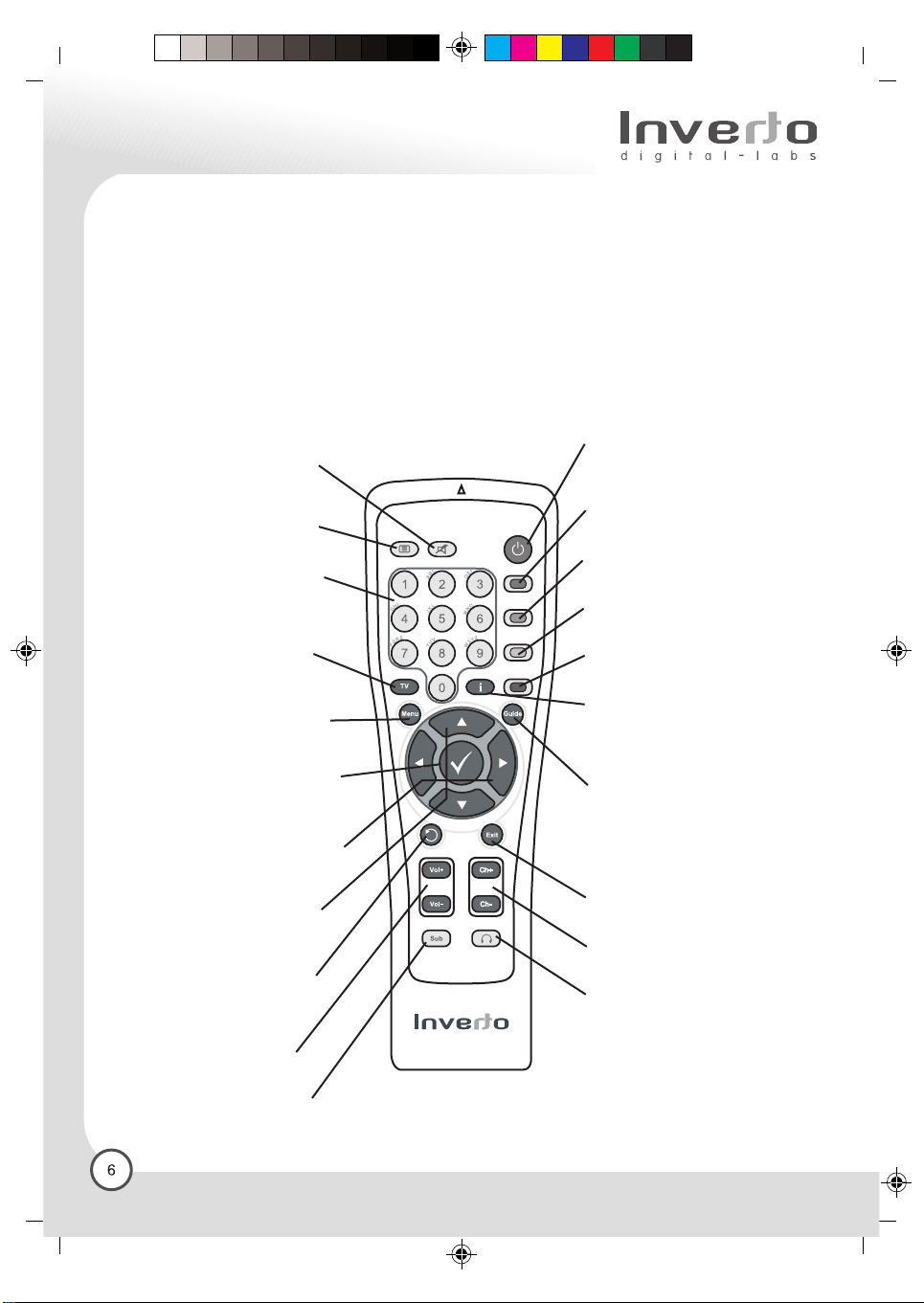
3.2 Control Pane
C M Y CM MY CY CMY K
Mute
To turn on/off sound (only for
Analogue Audio Output)
Teletext
To call up VBI teletext window
Number keys (0-9)
To select channels directly and
other commands
TV
To enter channel list window
and also switch your favourite
channel list
Menu
To display the “Main” Onscreen
Display (OSD)
Ok
To confirm choices and selection
of highlighted item
Left / Right buttons
To move in left/right directions within
the menus
Up / Down buttons
To move in up/down directions
in the menus. To select TV and
Radio channels
Last programme
Also to go back one level in the
menus
Volume
For Volume adjustment
Sub
To toggle for selecting desired
teletext subtitle track
On/Off (Standby)
To turn your STB on/off
(standby mode)
Red
Application defined function key
Green
Application defined function key
Yellow:
Application defined function key
Blue
Application defined function key
Information key
To call up extended channel
information (if available) and
channel status window
Guide
To obtain a list of programs on
available channels. This
information is only shown if your
Service Provider transmits program
information
Exit
To go back one level in the menus
Channel selection
For changing channels
HeadSet
To toggle for selecting desired
audio sound track
only for analogue audio output
Composite
1EnIDL5000HD-print.fh10 1/18/06 12:53 PM Page 7
4. Installing Your Receiver
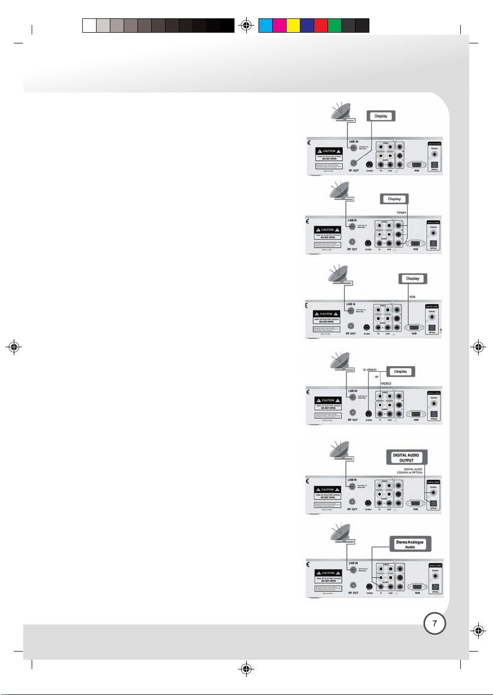
4.1 Connections to the satellite antenna
4.1.1 Cable connection
Connect the dish cable to the HD receiver LNB IN connector.
Also connect the cable between your analogue receiver LNB
IN and RF OUT connector on the rear of the receiver.
(Refer to A)
4.1.2 Video Connections
Adjust switch on the rear panel according to the format supported
by your display device, and it contains three modes:
A, B and C
4.1.2.1 Mode A (SD/HD, YPbPr)
Connect the YPbPr component video output socket on your
digital receiver to your display device’s YPbPr component video
input. Be sure to match the colours on the RCA sockets with
the coloured plugs. (Refer to B)
Note: When unit is in Mode A, there is no video output from the
CVBS TV socket.
4.1.2.2 Mode B (HD, RGB)
Connect the D-sub socket to your display device. (Refer to C)
Note: Cable is not supplied.
4.1.2.3 Mode C (SD, TV / CVBS)
Connect the CVBS composite video output socket on your digital
receiver to your TV’s CVBS video input socket.
Connect the S-Video (Y/C) component video output socket on
your receiver to your TV’s S-Video input socket. (Refer to D)
Note: Cable is not supplied.
Note: When unit is in Mode C, there is no output from the
YPbPr sockets.
C M Y CM MY CY CMY K
(A)
(B) Mode A
(C) Mode B
(D) Mode C
4.1.3 Audio Connections
If your TV set is equipped with Dolby Digital and/or MPEG audio
decoding capability, you may connect the Digital Audio output
by Optical or Coaxial RCA socket on your receiver to TV Digital
Audio input Optical or Coaxial RCA socket. (Refer to E) You
may also connect the digital audio output to your A/V receiver
assuming it is capable of decoding Dolby Digital /MPEG digital
audio stream.
If your TV set and/or A/V receiver does not support Dolby
Digital/MPEG decoding, you need to connect L/R Audio output
RCA sockets on your receiver to stereo L/R Audio inputs of TV
set and/or A/V receiver. (Refer to F). If your A/V receiver supports
Dolby Pro Logic decoder, you can switch ON
“Downmix-Surround” function.
Composite
(E)
(F)
1EnIDL5000HD-print.fh10 1/18/06 12:53 PM Page 8
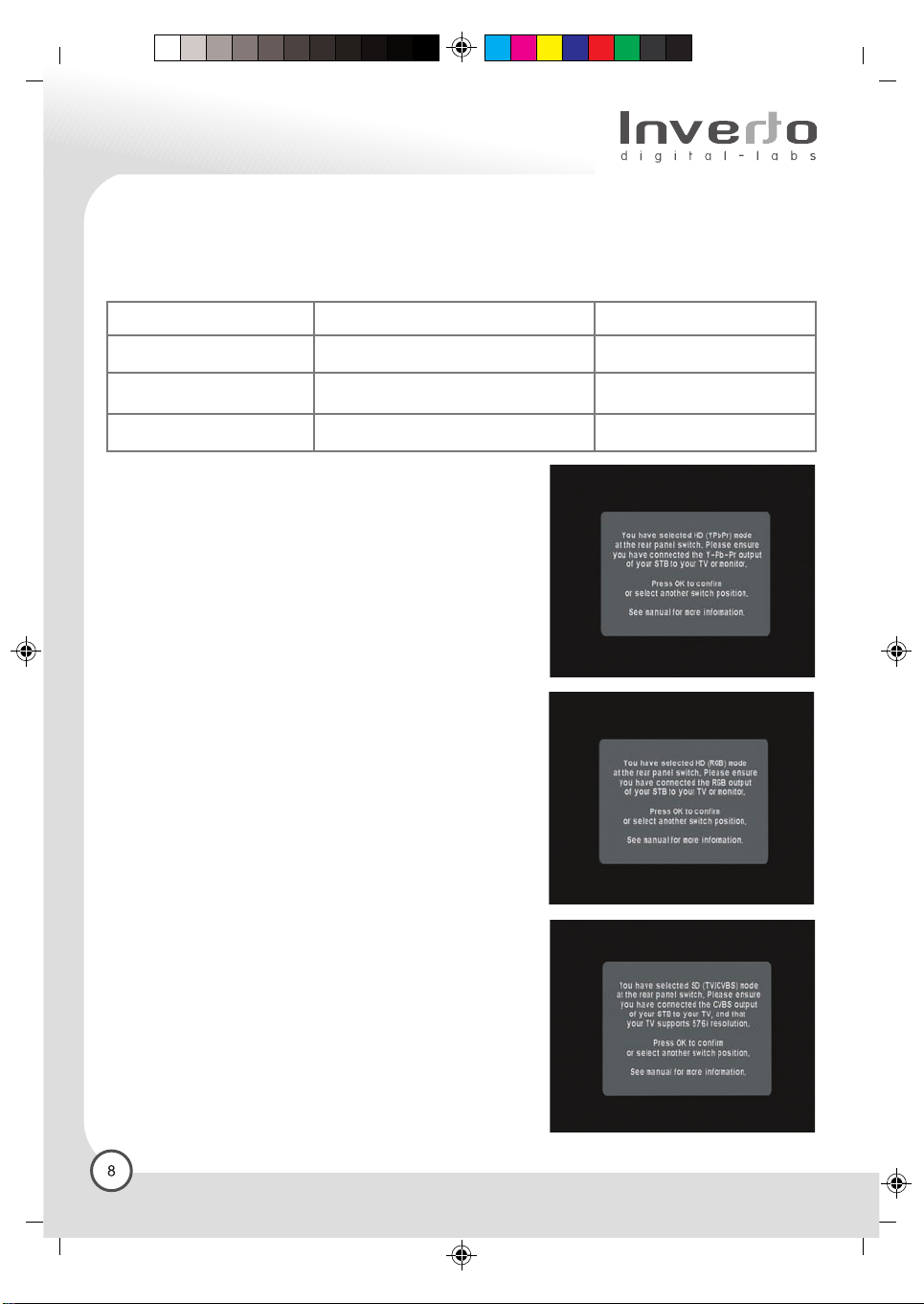
4.2 Output Mode Selection
After you have connected the AV cables for video and audio between your digital receiver and the display
device, check that the position of the output selection switch is correct for your chosen connection method
as in the table below.
C M Y CM MY CY CMY K
Switch Position
A
B
C
Switch on the digital receiver and the display device, and select
the correct AV input on the display device. The digital receiver
will take about 10 seconds to switch on. You may now start the
installation procedure.
The installation procedure is used to set up the video formats
that may be output from the digital receiver to the display device.
Video Output Format
YPbPr
RGB
TV / CVBS
4.2.1 Installation Format Selection
Use the Remote Control keypad to perform the digital receiver
format testing and installation. Follow the digital receiver’s onscreen instructions to do the installation.
4.2.2 Mode A (SD/HD, YPbPr)
The switch on the rear of the digital receiver must be in position
A, and the AV connections must be taken from the YPbPr RCA
sockets. The digital receiver display will show “HdcI”. Press
“Ok” to confirm the selection, or switch to another mode.
Proceed to INSTALLATION.
4.2.3 Mode B (HD, RGB)
The switch on the rear of the digital receiver must be in position
B, and the AV connections must be taken from the RGB HD15
socket. The digital receiver display will show “Hd r”. Press “Ok”
to confirm the selection, or switch to another mode. Proceed to
INSTALLATION.
Receiver Mode
SD / HD
HD
SD
Composite
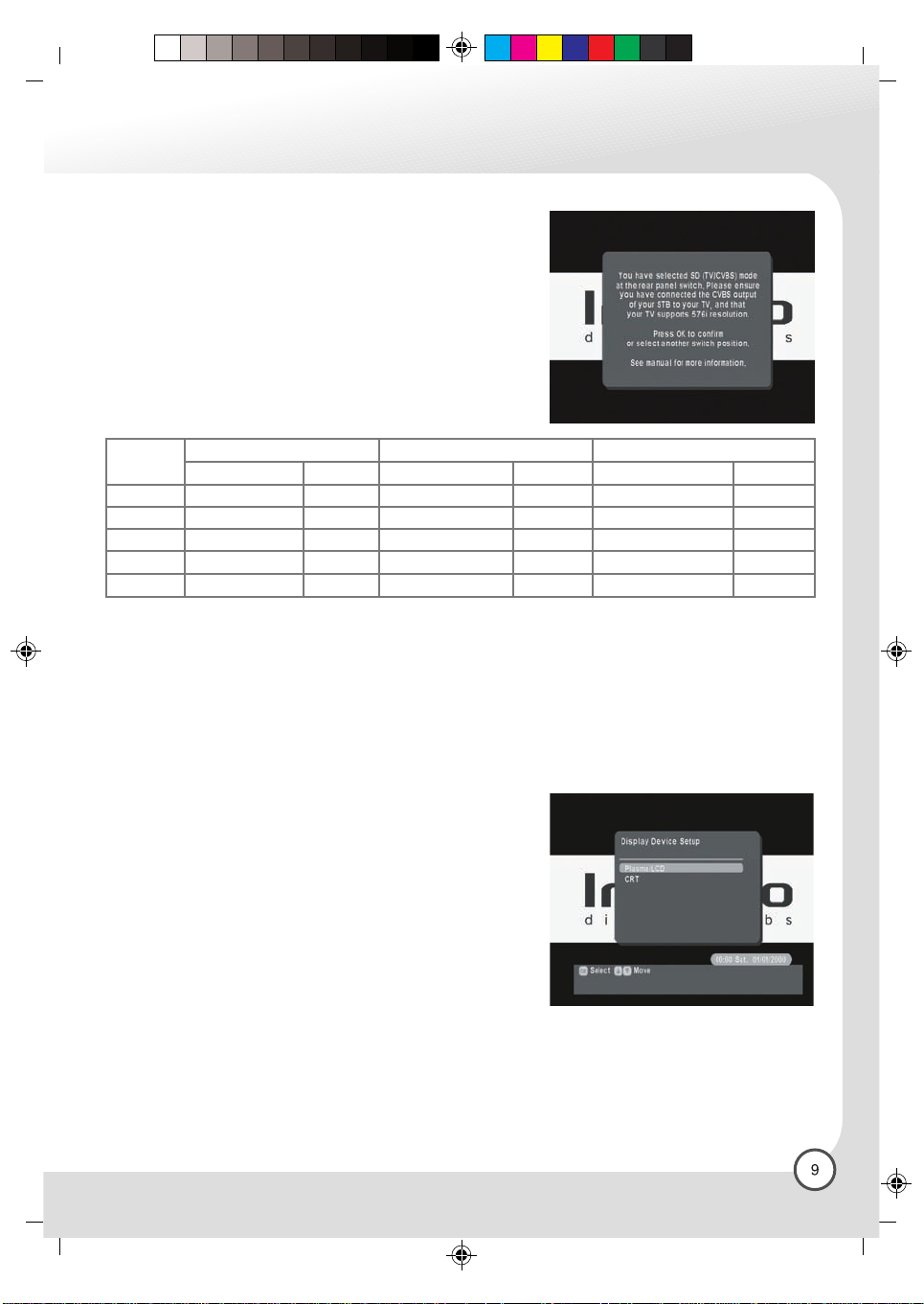
4.2.4 Mode C (SD, CVBS)
The switch on the rear of the digital receiver must be in position
C, and the AV connections must be taken from the CVBS TV
RCA socket. The digital receiver display will show “Sdtv”. Press
“Ok” to confirm the selection, or switch to another mode. Proceed
to INSTALLATION.
1EnIDL5000HD-print.fh10 1/18/06 12:53 PM Page 9
4.3 Installation
The on-screen display will ask which type of display device is
being used. You will have a choice of either Plasma / LCD (Flat
panel displays) or CRT (eg Standard television).
Select from the choices using the remote control keypad.
Note: Not all video formats are available in all modes. The following
table describes the available formats in each mode.
C M Y CM MY CY CMY K
HD (YPbPr)
LCD/Plasma CRT
576i
576p
1080i
X
X
X
1152i
720p
Table 1: Output format table
X
X
X
X
X
HD (RGB) SD (CVBS)
LCD/Plasma CRT LCD/Plasma CRT
XX
X
X
X
X
X
X
When all formats have been tested, a list of all accepted video formats will be displayed. You can select
the format you preferred from the list.
The accepted display formats are then displayed and you are requested to select your preferred
display format, the selected output format can be changed at any stage in the User Preferences menu.
Anytime you change the rear panel switch or change display device, you will have to restart the
procedure again.
If you choose an output format, which is nt supported by the display, you can recover by changing the
rear panel switch.
4.4 Display Device Setup
The on-screen display will ask which type of display device is
being used. You will have a choice of either Plasma / LCD (Flat
panel displays) or CRT (eg Standard television).
Composite
1EnIDL5000HD-print.fh10 1/18/06 12:53 PM Page 10
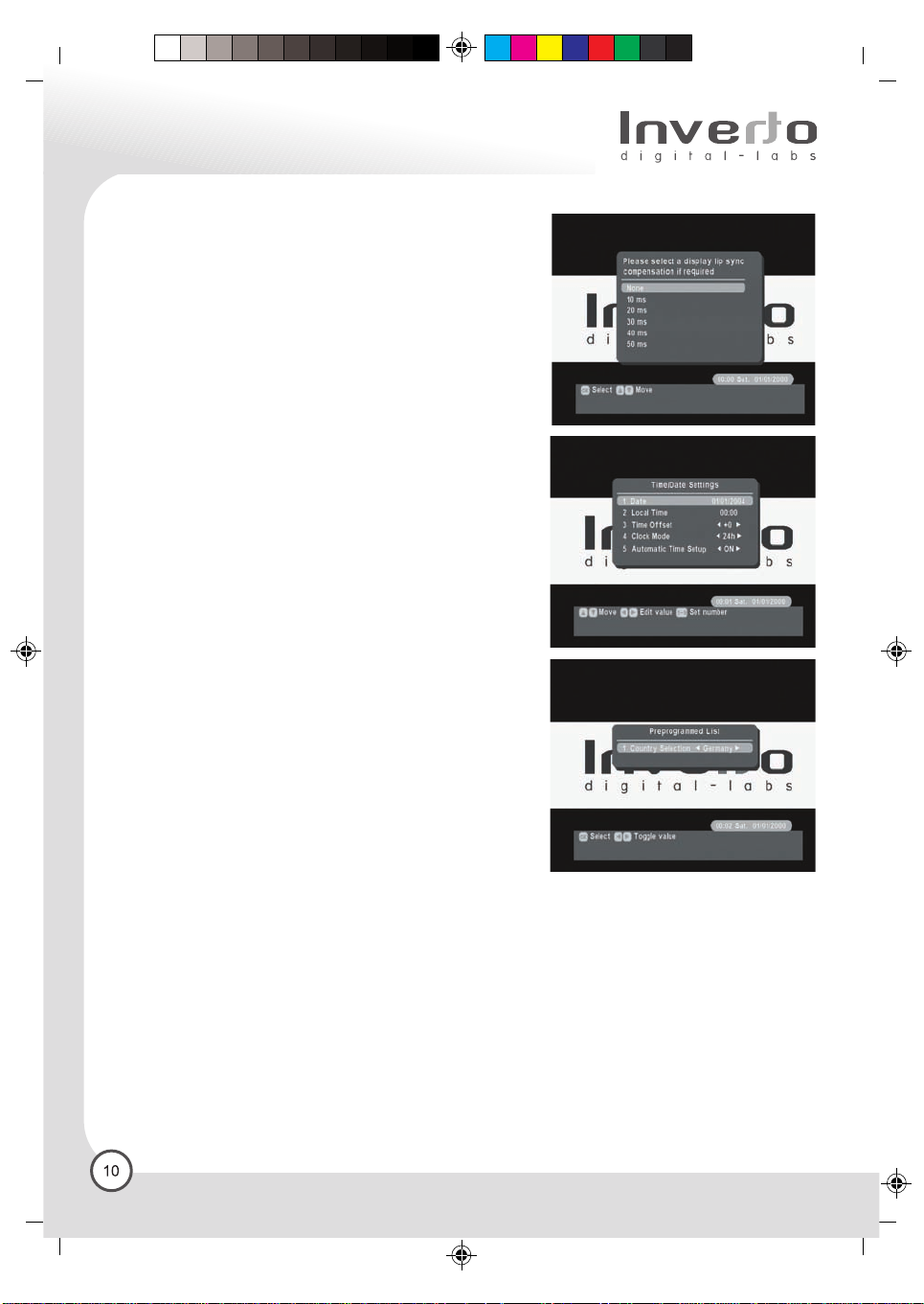
4.5 Audio Display setting
During the format set up, if you select Plasma / LCD as the
display type, your digital receiver will ask you to set up Lip
Sync Compensation. Generally speaking, Plasma Display
Panels introduce a slight time delay in the picture, which may
cause a problem with lip sync. Use “Up/Down” on the remote
control to select the delay and confirm by pressing OK. Typically
this delay is in the order of 20 – 40 ms. Select Aspect Ratio
The first time the digital receiver is installed, or after Factory
Reset. You will be asked to select Center Cut or Letter Box
(See chapter 6.2.2 for definition).
4.6 Time / Date Settings
Time/Date settings: If the ”Automatic Time Update” is set to
“On”, the receiver will receive the digital clock time and date
as broadcasted by the digital TV program providers, and will
apply these. The DVB standard will broadcast this in GMT
time zone. In order to display local time correctly, It may be
necessary to set a time offset, indicating the difference between
local time and GMT (e.g. in Germany daylight savings time
in summer is +2h, winter time is +1h)
Clock mode: The time can be displayed in 12 or
24-hour format.
C M Y CM MY CY CMY K
Automatic Time Update: The receiver can either receive the
current time via the digital TV programmers (On). or it can
calculate current time independently (Off).
4.7 Preprogrammed List
The final step of the installation procedure is to select the
country you are in. Based on your selection, a default program
list will be used in the database. You can change the country
at any time. Please refer to Section 6.6.4.3.
Composite

1EnIDL5000HD-print.fh10 1/18/06 12:53 PM Page 11
5. Operating Instructions:
Knowing your basic controls
To become acquainted with the operations and functions of your receiver, you must know how to use the
control buttons on the Front Panel and the Remote Control.
The following segment is an introduction to features that you will most commonly notice or use.
5.1 Switching On Your Digital Receiver
Before you switch on your receiver please ensure the power lead is plugged into a 240V AC socket.
Remember that as long as the digital receiver remains plugged into a 240V supply, the receiver will be in
constant “STANDBY”.
Switch on your receiver by pressing either the “Power” button on the remote control or the button on the
front panel. While the digital receiver is in normal viewing mode, the green LED lights up.
When not using the digital receiver, put your equipment in the “STANDBY” mode by pressing either one
of the “Power” buttons again. When the red “STANDBY” LED lights up, it indicates the digital receiver is
in “STANDBY” mode. The front panel will show current local time.
C M Y CM MY CY CMY K
Composite

1EnIDL5000HD-print.fh10 1/18/06 12:53 PM Page 12
6. Using The Main Menu
Your receiver comes with a directory of features or the Main OSD.
The Main is your gateway to customizing many of the features
offered by your receiver. To access the Main menu, press the
“Menu” button.
The Main feature comprises the following categories of services:
6.1 TV Guide
The receiver is able to display the program available on the
channel currently selected, indicating the current program as well
as following program.
This allows you quickly to obtain an overview of all program being
broadcast that day, and possibly those of the next day as well.
I the grid highlight the program by pressing the arrow buttons.
Once you have selected the desired choice (the highlighted block
will appear in a different shade), the detailed information of the
program will be shown in the lower rectangle and if the description
is too long, you can press the Blue key to scroll to next page. If
the broadcaster does not transmit detailed description of it, the
text “No descriptions available” will appear. If you wish to see
what programs are broadcasted on other channels, Press the
direction “Up/Down” keys to access the program list. Press the
“CH UP / CH DOWN” keys to change to another channel
If you wish to book a future program, highlight any program
(beyond the current time frame) by using the arrow buttons, press
“Ok” to confirm your selection. Note that if you highlight a program
currently broadcasted on another channel and press “Ok”, the
program is not booked. Instead, the receiver switches to that
channel directly.
C M Y CM MY CY CMY K
6.2 Personal Planner
This window will list all the programs you booked. You can remove
one program first by highlight it and then press the Red key. A
popup window will appear two minutes before the program starts.
The Auto means if you don’t reply to this Popup window, the box
will change to that program automatically, but the Notify won’t.
You can use Yellow key to toggle Auto/Notify function.
6.3 Channel List Manager
Main TV List: This window will list all TV programs available.
• Press the red function key to Favorite/Unfavourite a channel.
• Press the green function key to lock/unlock a channel
• Press the yellow function key to sort the list.
• Press Channel / on the remote control will scroll the
highlighted item.
• Press Left / Right arrow key will scroll the list by one page.
• Directly enter a channel by using the number keys on the
remote control.
• Use TV button to switch to main radio list.
Composite
1EnIDL5000HD-print.fh10 1/18/06 12:53 PM Page 13
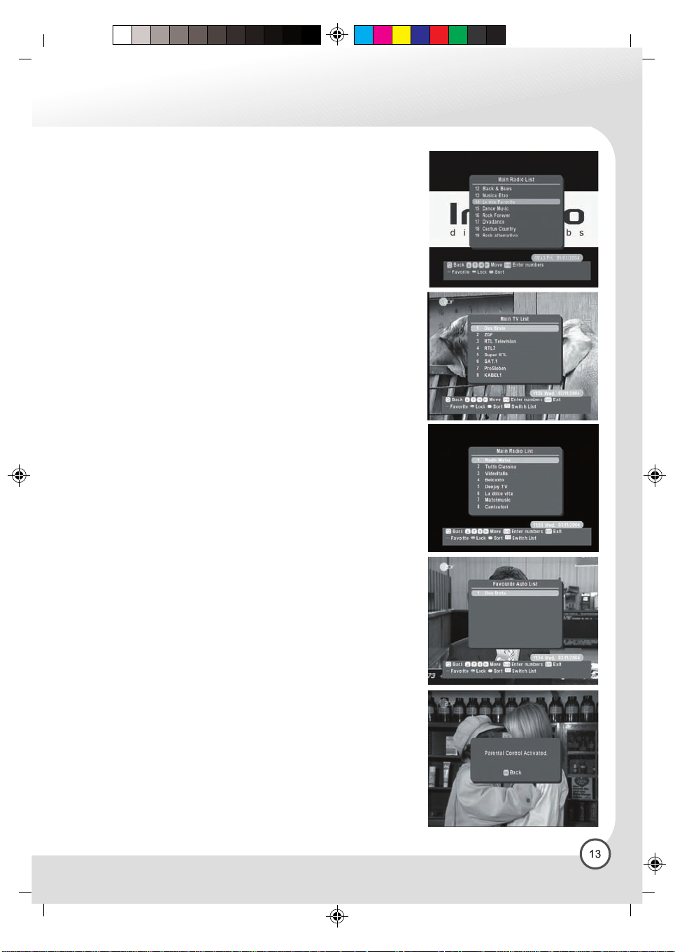
Main Radio List: This window will list all Radio
programs available.
• Use TV button to switch to Favourite TV List.
• Other buttons have the same functions as in Main TV List
Favourite TV List: This window will list all your
Favourite TV programs:
• Use TV button to switch to Favourite Radio List.
• Other buttons have the same functions as in Main TV List.
Favourite Radio List: This window will list all your favourite radio
programs.
• Use TV button to switch to Favourite Auto List.
• Other buttons have the same functions as in Main TV List.
Favourite Auto List: This window will list the most recently viewed
50 programs.
• Use TV button to switch back to Main TV List.
• Other buttons have the same functions as in Main TV List.
Note: You can only view the programs on the list when you exit the
Channel List Manager window.
C M Y CM MY CY CMY K
6.4 Parental Control
A feature enabling parents to “lock” programs that they consider
unsuitable for children’s viewing. Also the “Channel List Manager”,
“Installation / Setup” and “Factory Reset” are PIN protected once you
activate Parental Control.
6.4.1 Activate / Deactivate PIN Code
The PIN code default value is “ 0000 ”. Press the “OK/Menu” key to
call up the Main Menu, then select sub-display “Parental Control”.
Now select the line “Activate / Deactivate PIN Code”, and confirm by
pressing the “OK/Menu” key.
You can now enter the four-digit PIN Code; which is “0000 ” by
default. If the receiver accepts this PIN entry, you must confirm this
by means of the ok key. If the number is not accepted, you must
repeat the whole process.
6.4.2 Change PIN Code
From here you can change the password. Once the new password
is set DO NOT FORGET IT! Without the password, you cannot access
any functions that require you to provide the correct password! If
you forget your password, please contact customer service for help.
Composite
1EnIDL5000HD-print.fh10 1/18/06 12:53 PM Page 14
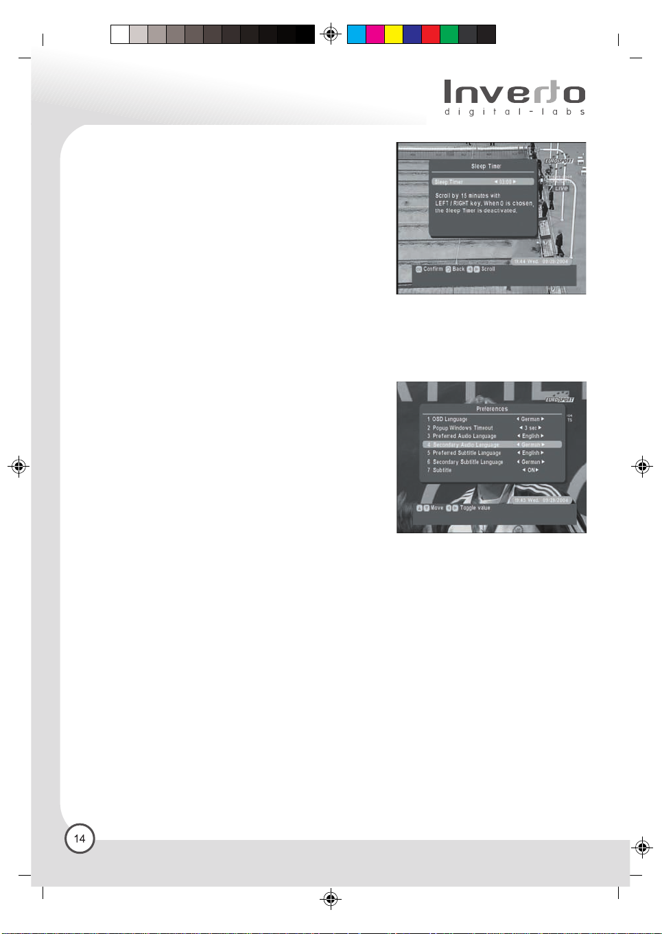
6.5 Sleep Timer
You can use the Sleep timer to specify a time (e.g. at night) at
which the receiver is to switch over into standby mode. This is
particularly useful if there is no person available at this time to
switch off the receiver manually. Press the “Menu” key to display
the Main Menu. Use directional keys to select the entry “ Sleep
Timer”, and confirm by pressing the “OK” key. The display “Sleep
Time” is now on screen, and you can use the LEFT / RIGHT
directional keys to change the time, at which the receiver should
switch itself off in 15-minute steps.
Press the “ OK” key to confirm your selection. The Sleep Timer
is active with immediate effect, and will count backwards the time
still remaining to switch off time. Exit from the “Sleep Timer” display
without modifying the value by pressing the “OK” key.
6.6 Installation / Setup
This is the place to set the basic parameters of your receiver.
6.6.1 User Preferences
From here, you may adjust various settings according to your
personal preference. Some programs offer a choice of audio
language. You can choose two of the available language as your
first and second choice for listening. Use the directional
“DOWN / UP” keys to select your preference, and you can use the
“LEFT / RIGHT” directional keys to change the toggle value,
Press the “ OK” key to confirm your selection.
Press the “EXIT” to exit this menu.
6.6.1.1 OSD Language:
OSD with Guiding menu is for installation and information.
The on-screen display may be shown in a variety of languages.
6.6.1.2 Popup Windows Timeout:
When you change channels, a banner will appear for certain time and then disappear automatically.
The setting here is to set the showing time of this banner.
6.6.1.3 Preferred Audio Language:
The receiver automatically selects your first choice as the Preferred Audio Language.
6.6.1.4 Secondary Audio Language:
If your first choice is not available, the second choice is automatically selected. If the second choice is not
available, the receivers use the original language of the program.
6.6.1.5 Preferred Subtitle Language:
Some programs offer a choice of subtitle language. Select your preference for the Subtitle Language.
6.6.1.6 Secondary Subtitle Language:
If your first choice is not available, the second choice is auto-matically selected. If the second choice is not
available, the receivers use the original language of the program.
C M Y CM MY CY CMY K
Composite
1EnIDL5000HD-print.fh10 1/18/06 12:53 PM Page 15
6.6.2 A/V Settings
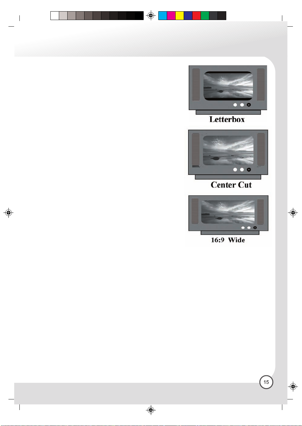
6.6.2.1 Screen Format
This setting affects the video format at the VCR / CVBS output.
If your display is 4:3 format and the transmission of a program
happens to be 16:9, the Letterbox mode will give you a complete
picture, but black areas will appear at the top and bottom.
Alternatively you can choose the Center Cut mode to play the
program in a full-screen format, however information on the left and
right sides may be cut off.
If your display is 16:9 format, then set the mode at Wide Screen.
If a program happens to be in 4:3, black areas will appear at the left
and right of the screen in order to present the picture in a correct
aspect ratio.
6.6.2.2 Display Type:
This menu contains two options: Plasma / LCD and CRT. Normally,
different display equipment may have different delay in picture,
which may cause slight problem in lip sync. This feature allows you
to use “Left/Right” to select your choice according to your actual
video display equipment.
6.6.2.3 Default audio mode:
There are four default audio modes: Stereo / Left / Right / Mono.
Choose the one you prefer, normally it should be Stereo.
C M Y CM MY CY CMY K
6.6.2.4 Digital Audio:
For each Audio Mode, you can have different Digital Audio
Selection Options.
*Bitstream: select this if your TV or A / V receiver has a digital audio input and can decode Dolby Digital.
*PCM (stereo): select this if your TV or A / V receiver has a digital audio input but can not decode Dolby
Digital.
*Off: select this if you want the digital audio output to mute when a Dolby Digital program is being received.
6.6.2.5 Downmix – Surround
You can toggle Downmix-Surround on or off by pressing “Left/Right” and “Ok” OK.
On: Surround information will be included in stereo output (Lt/Rt)
Off: Pure stereo audio output (L/R)
6.6.2.6 Select output format
After the initial format setting procedure, the output format still can be changed according to your preference.
The formats allowed to select are depending on the initial format checking process, that is, only the formats
that your display device supports.
6.6.2.7 Audio delay time:
Different displays may have different delay in displaying pictures, which may cause a slight problem with
lip sync. This feature allows you to use “Left/Right” to select your choice according to your actual video
display equipment, in order to compensate for this delay. The delay time depends on which choice appears
to provide best performance of lip sync on your display device.
Composite
1EnIDL5000HD-print.fh10 1/18/06 12:53 PM Page 16
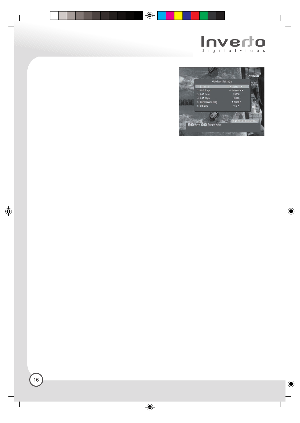
6.6.3 Outdoor Settings
The receiver must be fed with information as to how many
satellite positions can be received by the satellite antenna
(the number of LNBs), and which switching signals are available
to control the individual components of the installation, such as
the LNBs or the multi switches.
6.6.3.1 Satellite
Here you should select from a list of all European satellite
positions, the current position at which the LNB being
configured is the one currently showed (e.g. Astra1, Hotbird
or another satellite).
6.6.3.2 LNB Type
The default setting here is “Universal”. If you are using a different type of LNB, use left/right key to select
the appropriate type of LNB. You can choose here a motorized LNB, and this will give access to the Motor
Settings menu.
6.6.3.3 LOF Low
The receiver needs to know precisely the two local oscillator frequencies (LOF) in the LNB (Standard:
Universal LNB with 9,75/10,6 GHz). Depending on the type of LNB selected, LOW frequencies may already
be suggested at this stage. These can, however, be changed as requited. You can also enter any specific
value you require.
6.6.3.4 LOF High
The receiver needs to know precisely the two local oscillator frequencies (LOF) in the LNB (Standard:
Universal LNB with 9,75/10,6 GHz). Depending on the type of LNB selected, frequencies may already be
suggested at this stage. You can also enter any specific value you require.
6.6.3.5 Band Switching
Here you can specify whether the receiver is to switch between the low and high bands by means of
a 22KHz switching signal (Standard for Universal LNB: “Auto”), or whether the signal should be transmitted
continuously or not at all.
6.6.3.6 Primary DiSEqC
The receiver automatically selects your first choice as the Primary DiSEqC.
6.6.3.7 Secondary DiSEqC
If your first choice is not available, the second choice is automatically selected. If the second choice is
not available, the receiver will use the original DisEqC of the program.
C M Y CM MY CY CMY K
Composite
1EnIDL5000HD-print.fh10 1/18/06 12:53 PM Page 17
6.6.3.8 Motor Settings
If you wish to connect the receiver to a rotating antenna (DiSEqC Level 1.2), call up the Main Menu, then
pressing Installation / Setup, then pressing “ Outdoor Settings”, then go to entry “ LNB Type” and use the
/ directional keys to select the setting “Motorized” for every LNB number, which has to be controlled by
the motor. Where you will find a facility for setting the position of the antenna manually for the various
satellite positions, and can then store these positions in memory. In the window “ Motor settings”, select
from the displayed list the satellite you want to reach with the next antenna position. The receiver at this
stage has already registered which transponders are available on this satellite, and will indicate the signal
strength and quality in the form of a bar graph. You can use this to find the optimum for the antenna.
In order to rotate the antenna towards the East or West, use the directional keys to select either “Move
coarse” or “More fine”. When the satellite position has been found, select “Save Position” in order to store
this permanently. In future, the receiver will automatically turn the antenna to this position whenever you
tune to a programmed slot available from this position.
Apart from storing all required satellite positions, you should also make a point of programming an easterly
and a westerly limit position for the motor. This is particularly important if other buildings or structures in
the vicinity restrict the rotation of the antenna. These could damage the antenna, motor or surrounding
objects if pre-programming does not restrict the limit of rotation.
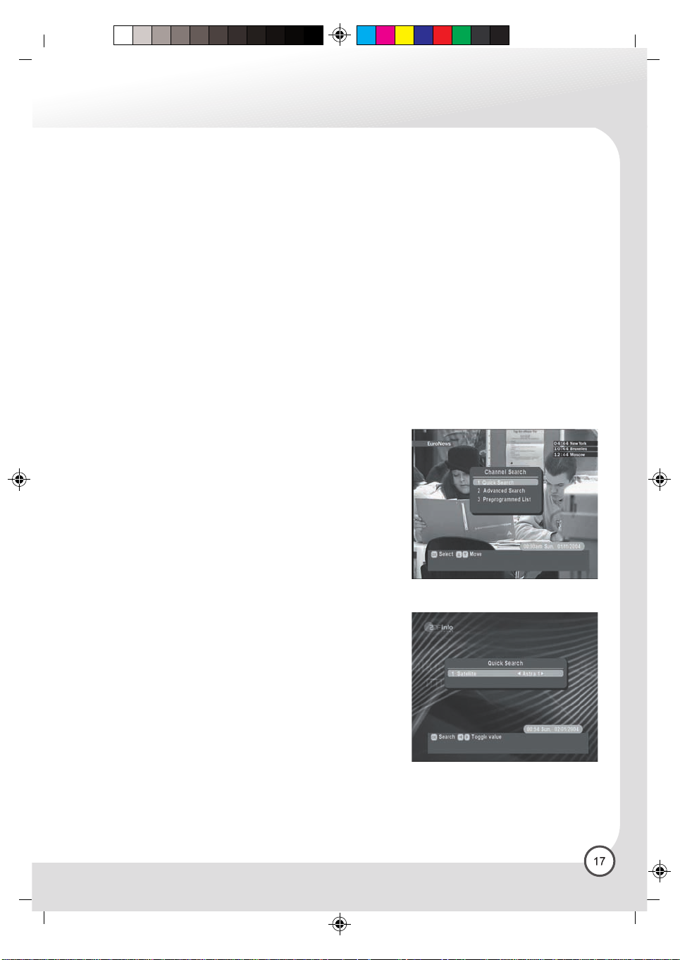
6.6.4 Channel Search
C M Y CM MY CY CMY K
New digital satellite TV and radio program are added almost on a
day daily basis, or existing program will change their frequency.
If you wish to receive these programs, you must allocate them to
specific program slots in the program list, and store them in memory.
The program search function is designed to assist you in this
activity, and there are various types of program search available.
Several procedures can be followed in order to initiate a program
search. Press the “Menu” key to call up the Main Menu, then using
the / directional keys select the sub-menu “Installation / Setup”,
followed by “Channel Search”, confirming your selection in each
case by pressing the “OK” key. Here you can decide between the
three options.
6.6.4.1 Quick Search
Use the automatic program search to allow your receiver to search
through an entire satellite position for new program. In this case,
the entire frequency range of the satellite is searched. The following
information must be input to the receiver:
Satellite: First select the satellite position to be searched. Below
this you will see a display of the current signal strength.
All newly found program would now be displayed on the following
page. At the end, the result of the program search will be displayed.
The search procedure can be terminated at any time by pressing
the “EXIT” key.
Composite
1EnIDL5000HD-print.fh10 1/18/06 12:53 PM Page 18
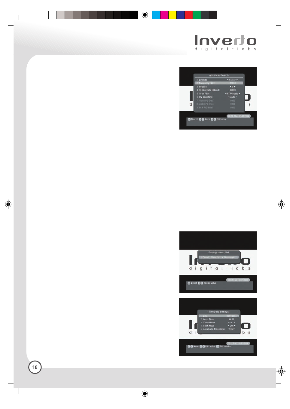
6.6.4.2 Advanced Search
In addition to the automatic search, a manual search procedure
is also available. In this case you must search specifically for the
program on a specific satellite transponder. Unlike the automatic
search procedure, here you must enter all reception parameters
explicitly.
The technical reception parameters that must be entered in this
display can be obtained either from satellite magazines, or from
the relevant program provider.
The following information must be input:
Satellite: First select the satellite position to be searched. Below this you will see a display of the current
signal strength.
Frequency: Here you must enter the five-digit transponder frequency, e.g. 11836 for 11.836GHz.
Polarity: Here you must enter the polarization plane of the transponder (“Horizontal” or “Vertical”).
Symbol rate: Either select one of the two usual rates commonly found on the Astra and Eutelsat satellites,
22.000 as well as 27.500 symbols/s, or enter a specific value manually. The receiver is equipped to process
symbol rates between 2.000 and 45.000 symbols/s.
Scan Filter: There are three choices:
FTA: Only search free-to-air programs.
FTA+Irdeto: Search free-to-air plus Irdeto scrambled programs
All: Search all kinds of programs, including other CA systems.
PID Video: Packet identifier for the video signal
PID Audio: Packet identifier for the audio signal
PID PCR: Program Clock Reference
Now press the red function key to initiate the manual program search. All program broadcasting within the
framework of specified parameters will be displayed, one after the other, on the following page. You can
then decide whether you want to store the newly found program in memory, or whether you wish to discard
them. The search procedure can be terminated at any time by pressing the “EXIT” key.
C M Y CM MY CY CMY K
Composite
6.6.4.3 Preprogrammed List
The receiver automatically selects your country name. The subdisplay “ Do you want to reinitialise the program list? “, Please
pressing the “ OK” key, then will be initialising the program. Please
wait about 15 seconds.
6.6.5 Time / Date Settings
Time/Date settings: If the ”Automatic Time Update” is set to “On”,
the receive will receive the digital clock time and date as broadcast
by the digital TV programmed providers. The DVB standard will
broadcast this in GMT time zone. In order to display local time
correctly, It may be necessary to set a time offset, indicating the
difference between local time and GMT (e.g. in Germany daylight
savings time in summer is +2h, winter time is +1h)
Clock mode: The time can be displayed in 12 or 24-hour format.
Automatic Time Update: The receiver can either receive the
Current time via the digital TV programmers (On),
Or it can calculate current time independently (Off).
1EnIDL5000HD-print.fh10 1/18/06 12:53 PM Page 19
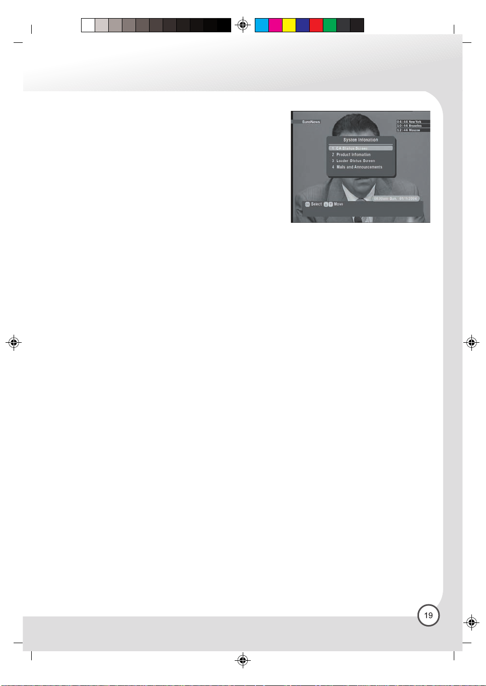
6.6.6 System information
The sub-display “System information” provides you with all data
relating to the hardware and software of the receiver. Each unit
has is own unique serial number (Product ID). From here, you
can get general information about the Receiver ID, software and
hardware version on which it is operating.
6.6.6.1 CA status Screen
From the sub-display “CA status Screen”, you can get general
information about Transport Stream Information.
6.6.6.2 Product Information
From the sub-display “Product Information”, you can get general information about serial number, smart
card version, detail s/w version information.
6.6.6.3 Loader Status Screen
The sub-display “Loader Status Screen “ is only for Irdeto reference.
6.6.6.4 Mail and Announcements
Important messages are periodically sent to our customer. Messages announce upcoming programs, and
promote platform upgrades and enhancements, or remind you of a payment.
If you receive a message, the “message” icon appears on left-top corner of display device.
C M Y CM MY CY CMY K
6.6.7 Software Upgrade
The receiver software can be updated via satellite (OTA- over the air) and can thus be kept up to date at
all times. The software updates are broadcast from the satellite position Astra 19,2¢X East. If you have a
rotating antenna, please ensure it is aligned for this position before attempting a software update. Choose
the option “Software Update” and follow the instructions appearing on the TV set. The whole process might
take around 30 minutes.
6.7 Factory Reset
If you wish to reset all previous new settings, you can use this feature to do so. Once you decide to
restore default (factory) settings, all previous settings will be lost. Please be very careful before you confirm
this action.
Composite
1EnIDL5000HD-print.fh10 1/18/06 12:53 PM Page 20
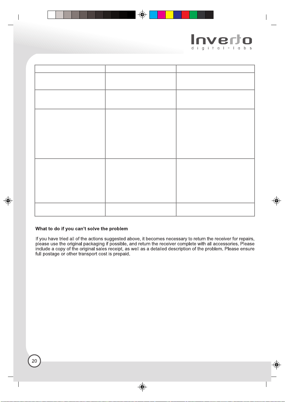
7. Troubleshooting
Problem Possible causes Solution
No box reaction
Mains power cable not
connected to mains.
C M Y CM MY CY CMY K
Check mains cable and plug
The display on the panel does
not light up/is not lit
No sound, no picture
The remote control is
not working
Forgot PIN Incorrect code entered Contact your service provider
Power Mains cable is
not connected
Satellite antenna may not be
precisely positioned for reception
from a specific satellite.
Short circuit in satellite
connection cable.
The A/V cord is not properly
placed
Wrong selection of output mode
Battery exhausted
Florescent light interfering with
the remote control
Remote control is incorrectly
aimed
Check that the mains cable is
plugged in to the power socket
Check the cable connections and
other equipment connected to your
receiver
Try another output configuration
Change the batteries
Switch off the light
Aim the remote control at
the receiver
Composite
 Loading...