

Page 1
AC Variable Speed Drive
0.75 - 250kW / 1 - 350HP
200 - 600V Single and 3 Phase Input
User Guide
Quick Start Up
General Information
and Ratings
Mechanical Installation
Electrical Installation
Keypad and Display Operation
Parameters
Control Terminal
Functions
Extended
Parameters
1
2
3
4
5
6
7
8
Serial
Communications
Technical Data
Troubleshooting
9
10
11
Page 2

1. Quick Start Up
............................
4
5. Keypad and Display Operation
......................
33
1.1. Important Safety Information
1.2. Quick Start Process
2. General Information and Ratings
2.1. Identifying the Drive by Model Number
2.2. Product Rating Label Location
2.3. Understanding the Rating Label
2.4. Drive Model Numbers – IP20
2.5. Drive Model Numbers – IP55
2.6. Drive Model Numbers – IP66 Non-switched
2.7. Drive Model Numbers – IP66 Switched
3. Mechanical Installation
3.1. General
3.2. Before Installation
3.3. UL Compliant Installation
3.4. Installation Following a Period of Storage
3.5. Mechanical Dimensions and Weight
......................................
.............................
....................
............................
...................
.................
..................
..................
....................
.......................
...........
..........
.....
..........
........
............
4
5
6
6
6
7
7
9
10
11
12
12
12
12
12
13
5.1. Keypad and Display Layout
5.2. Selecting the Language on the TFT and OLED Display
5.3. Additional Display Messages
5.4. Changing Parameters
5.5. Parameter Factory Reset / User Reset
5.6. Resetting the Drive Following a Trip
5.7. Keypad Shortcuts
6. Parameters
6.1. Parameter Set Overview ...................................
6.2. Parameter Group 1 – Basic Parameters ......................
7. Control Terminal Functions ...........................
7.1. Control Source Selection
7.2. Digital Input Configuration Parameter P1-13. . . . . . . . . . . . . . . . . . .
7.3. Example Connection Schematics ............................
8. Extended Parameters
8.1. Parameter Group 2 - Extended Parameters ....................
.......................................
........................................
...............................
.............................
....................................
......................
........................
..................................
..............................
.......
33
34
34
35
35
35
36
37
37
37
40
40
42
43
47
47
3.6. Guidelines for Enclosure Mounting (IP20 Units) .....
3.7. Mounting the Drive – IP20 Units. . . . . . . . . . . . . . . . . . .
3.8. Guidelines for Mounting (IP55 Units)
3.9. Guidelines for Mounting (IP66 Units)
3.10. Removing the Terminal Cover
3.11. Routine Maintenance
4. Electrical Installation
4.1. Connection Diagram
4.2. Protective Earth (PE) Connection
4.3. Incoming Power Connection
4.4. Operation of 3 Phase drives from a Single Phase
Supply
...........................................
4.5. Operation with DC Power Supply or Common DC
Bus
..............................................
4.6. Motor Connection
4.7. Motor Terminal Box Connections
4.8. Connecting a Brake Resistor
4.9. Control Terminal Wiring
..........................
.......................
...........................
. . . . . . . . . . . . . . . . . . . . . . . . . . . . .
........................
............
............
...................
.................
....................
................
....................
16
17
17
18
19
19
20
20
21
22
23
23
23
23
24
25
8.2. Parameter Group 3 – PID Control ...........................
8.3. Parameter Group 5 – Communication Parameters .............
8.4. Advanced Parameters .....................................
8.5. Parameter Group 0 – Monitoring Parameters (Read Only) ......
9. Serial Communications ........................... 64
9.1. RS-485 Communications
9.2. Modbus RTU Communications ..............................
9.3. CAN Open Communication ...............................
10. Technical Data ................................. 72
10.1. Environmental ...........................................
10.2. Input/Output Power and Current Ratings ....................
10.3. Input Power Supply Requirements ..........................
10.4. Additional Information for UL Approved Installations ...........
10.5. Derating Information .....................................
10.6. Internal EMC Filter and Varistors – Disconnection Procedure ....
11. Troubleshooting ................................ 78
11.1. Fault Messages ..........................................
.................................
52
56
58
62
64
65
67
72
72
75
75
76
76
78
4.10. Control Terminal Connections
4.11. IP66 Switched Version Integrated Control Switch
and Potentiometer Wiring
4.12. Motor Thermal Overload Protection
4.13. EMC Compliant Installation
4.14. Safe Torque Off
2 | Optidrive P2 User Guide | Version 3.04 www.invertekdrives.com
..............................
..................
..........................
.............
....................
26
27
27
28
29
Page 3

Declaration of Conformity
Invertek Drives Ltd hereby states that the Optidrive ODP-2 product range conforms to the relevant safety provisions of the following
council directives:
2014/30/EU (EMC) and 2014/35/EU (LVD)
Designed and manufacture is in accordance with the following harmonised European standards:
EN 61800-5-1: 2007+A1:2017
EN 61800-3: 2004 /A1 2012 Adjustable speed electrical power drive systems. EMC requirements and specific test methods
EN 55011: 2007 Limits and Methods of measurement of radio disturbance characteristics of industrial, scientific
EN60529: 1992 Specifications for degrees of protection provided by enclosures
Adjustable speed electrical power drive systems. Safety requirements. Electrical, thermal and energy.
and medical (ISM) radio-frequency equipment (EMC)
Safe Torque OFF (“STO”) Function
Optidrive P2 incorporates a hardware STO (Safe Torque Off) Function, designed in accordance with the standards listed below.
Standard Classification Independent Approval
EN 61800-5-2:2016 Type 2
EN ISO 13849-1:2015 PL “d”
EN 61508 (Part 1 to 7):2010 SIL 2
EN60204-1:2006 + A1:2009 + AC: 2010 Uncontrolled Stop “Category 0”
EN 62061:2005/A2:2015 SIL CL 2
*TUV
Electromagnetic Compatibility
All Optidrives are designed with high standards of EMC in mind. All versions suitable for operation on Single Phase 230 volt and Three Phase
400 volt supplies and intended for use within the European Union are fitted with an internal EMC filter. This EMC filter is designed to reduce
the conducted emissions back into the mains supply via the power cables for compliance with the above harmonised European standards.
It is the responsibility of the installer to ensure that the equipment or system into which the product is incorporated complies with the
EMC legislation of the country of use, and the relevant category. Within the European Union, equipment into which this product is
incorporated must comply with the EMC Directive 2014/30/EU. This User Guide provides guidance to ensure that the applicable
standards may be achieved.
Copyright Invertek Drives Ltd © 2020
All rights reserved. No part of this User Guide may be reproduced or transmitted in any form or by any means, electrical or mechanical
including photocopying, recording or by any information storage or retrieval system without permission in writing from the publisher.
2 Year Warranty
All Invertek Optidrive units carry a 2 year warranty against manufacturing defects from the date of manufacture. The manufacturer
accepts no liability for any damage caused during or resulting from transport, receipt of delivery, installation or commissioning. The
manufacturer also accepts no liability for damage or consequences resulting from inappropriate, negligent or incorrect installation,
incorrect adjustment of the operating parameters of the drive, incorrect matching of the drive to the motor, incorrect installation,
unacceptable dust, moisture, corrosive substances, excessive vibration or ambient temperatures outside of the design specification.
The local distributor may offer different terms and conditions at their discretion, and in all cases concerning warranty, the local
distributor should be contacted first.
This user guide is the “original instructions” document. All non-English versions are translations of the
“original instructions”.
The contents of this User Guide are believed to be correct at the time of printing. In the interest of a commitment to a policy of
continuous improvement, the manufacturer reserves the right to change the specification of the product or its performance or the
contents of the User Guide without notice.
This User Guide is for use with version 2.50 Firmware. User Guide Revision 3.04.
Invertek Drives Ltd adopts a policy of continuous improvement and whilst every effort has been made to provide accurate and up to
date information, the information contained in this User Guide should be used for guidance purposes only and does not form the part
of any contract.
When installing the drive on any power supply where the phase-ground voltage may exceed the phase-phase voltage
(typically IT supply networks or Marine vessels) it is essential that the internal EMC filter ground and surge protection varistor
ground (where fitted) are disconnected. If in doubt, refer to your Sales Partner for further information.
This manual is intended as a guide for proper installation. Invertek Drives Ltd cannot assume responsibility for the compliance
or the non-compliance to any code, national, local or otherwise, for the proper installation of this drive or associated
equipment. A hazard of personal injury and/or equipment damage exists if codes are ignored during installation.
This Optidrive contains high voltage capacitors that take time to discharge after removal of the main supply. Before
working on the drive, ensure isolation of the main supply from line inputs. Wait ten (10) minutes for the capacitors to
discharge to safe voltage levels. Failure to observe this precaution could result in severe bodily injury or loss of life.
Only qualified electrical personnel familiar with the construction and operation of this equipment and the hazards involved
should install, adjust, operate, or service this equipment. Read and understand this manual and other applicable manuals
in their entirety before proceeding. Failure to observe this precaution could result in severe bodily injury or loss of life.
Version 3.04 | Optidrive P2 User Guide | 3www.invertekdrives.com
Page 4

Quick Start Up
1
1. Quick Start Up
1.1. Important Safety Information
Please read the IMPORTANT SAFETY INFORMATION below, and all Warning and Caution information elsewhere.
Danger: Indicates a risk of electric shock, which,
if not avoided, could result in damage to the
equipment and possible injury or death.
This variable speed drive product (Optidrive) is intended for
professional incorporation into complete equipment or systems
as part of a fixed installation. If installed incorrectly it may present
a safety hazard. The Optidrive uses high voltages and currents,
carries a high level of stored electrical energy, and is used to
control mechanical plant that may cause injury. Close attention
is required to system design and electrical installation to avoid
hazards in either normal operation or in the event of equipment
malfunction. Only qualified electricians are allowed to install and
maintain this product.
System design, installation, commissioning and maintenance must
be carried out only by personnel who have the necessary training
and experience. They must carefully read this safety information
and the instructions in this Guide and follow all information
regarding transport, storage, installation and use of the Optidrive,
including the specified environmental limitations.
Do not perform any flash test or voltage withstand test on the
Optidrive. Any electrical measurements required should be
carried out with the Optidrive disconnected.
Electric shock hazard! Disconnect and ISOLATE the Optidrive
before attempting any work on it. High voltages are present
at the terminals and within the drive for up to 10 minutes after
disconnection of the electrical supply. Always ensure by using a
suitable multimeter that no voltage is present on any drive power
terminals prior to commencing any work.
Where supply to the drive is through a plug and socket connector,
do not disconnect until 10 minutes have elapsed after turning off
the supply.
Ensure correct earthing connections and cable selection as
defined by local legislation or codes. The drive may have a
leakage current of greater than 3.5mA; furthermore the earth
cable must be sufficient to carry the maximum supply fault current
which normally will be limited by the fuses or MCB. Suitably rated
fuses or MCB should be fitted in the mains supply to the drive,
according to any local legislation or codes.
Do not carry out any work on the drive control cables whilst
power is applied to the drive or to the external control circuits.
The “Safe Torque Off” Function does not prevent high voltages
from being present at the drives power terminals.
Within the European Union, all machinery in which this product is used
must comply with the Machinery Directive 2006/42/EC, Safety of
Machinery. In particular, the machine manufacturer is responsible for
ensuring that the electrical equipment complies with EN60204-1 and
providing a disconnecting device which must be one of the following
types:
A switch-disconnector, utilization category AC-23B (EN 60947-3).
A circuit breaker suitable for isolation in accordance with
For installation in other regions, conformance with local electrical
regulations and codes of practice must be adhered to.
The level of integrity offered by the Optidrive control input functions –
for example stop/start, forward/reverse and maximum speed, is not
sufficient for use in safety-critical applications without independent
channels of protection. All applications where malfunction could cause
injury or loss of life must be subject to a risk assessment and further
protection provided where needed.
The driven motor can start at power up if the enable input signal is present.
The STOP function does not remove potentially lethal high voltages.
ISOLATE the drive and wait 10 minutes before starting any work on it.
Never carry out any work on the Drive, Motor or Motor cable whilst
the input power is still applied.
The Optidrive can be programmed to operate the driven motor at
speeds above or below the speed achieved when connecting the
motor directly to the mains supply. Obtain confirmation from the
manufacturers of the motor and the driven machine about suitability for
operation over the intended speed range prior to machine start up.
Do not activate the automatic fault reset function on any systems
whereby this may cause a potentially dangerous situation.
IP55 and IP66 drives provide their own pollution degree 2
environments. IP20 drives must be installed in a pollution degree 2
environment, mounted in a cabinet with IP54 or better.
Optidrives are intended for indoor use only.
When mounting the drive, ensure that sufficient cooling is provided. Do
not carry out drilling operations with the drive in place, dust and swarf
from drilling may lead to damage.
The entry of conductive or flammable foreign bodies should be
prevented. Flammable material should not be placed close to the drive.
Relative humidity must be less than 95% (non-condensing).
Ensure that the supply voltage, frequency and no. of phases (1 or 3
phase) correspond to the rating of the Optidrive as delivered.
Never connect the mains power supply to the Output terminals U, V, W.
Do not install any type of automatic switchgear between the drive and
the motor.
Wherever control cabling is close to power cabling, maintain a
minimum separation of 100 mm and arrange crossings at 90 degrees.
Ensure that all terminals are tightened to the appropriate torque setting.
Do not attempt to carry out any repair of the Optidrive. In the case of
suspected fault or malfunction, contact your local Invertek Drives Sales
Partner for further assistance.
Do not operate the drive with any of the enclosure covers removed.
Danger: Indicates a potentially hazardous situation
other than electrical, which if not avoided, could
result in damage to property.
EN 60947-2.
A disconnector with an integrated auxiliary contact that ensures under
all circumstances the switching devices break the load circuit prior to
opening of the main contacts of the disconnector (EN 60947-3).
4 | Optidrive P2 User Guide | Version 3.04 www.invertekdrives.com
Page 5

1.2. Quick Start Process
Step Action See Section Page
1 Identify the Model Type and ratings of your drive
from the model code on the label. In particular:
- Check the voltage rating suits the incoming supply
- Check the output current capacity meets or
exceeds the full load current for the intended
motor
- Check the enclosure type is suitable for the
intended mounting location.
2 Unpack and check the drive.
Notify the supplier and shipper immediately of any
damage.
3 Ensure correct ambient and environmental conditions
for the drive are met by the proposed mounting
location.
4 Install the drive in a suitable cabinet (IP20 Units),
ensuring suitable cooling air is available.
Mount the drive to the wall or machine (IP55 &
IP66).
5 Select the correct power and motor cables
according to local wiring regulations or code, noting
the maximum permissible sizes.
6 For IT Supply network, or any power supply type
where the phase – earth voltage may exceed
the phase – phase voltage (such as ungrounded
supplies), disconnect the EMC filter before
connecting the supply.
7 Check the supply cable and motor cable for faults or
short circuits.
8 Route the cables
9 Check that the intended motor is suitable for use,
noting any precautions recommended by the supplier
or manufacturer.
2.1. Identifying the Drive by Model Number
2.3. Understanding the Rating Label
2.4. Drive Model Numbers – IP20
2.5. Drive Model Numbers – IP55
2.6. Drive Model Numbers – IP66 Non-switched
3.1. General
10.1. Environmental 72
3.1. General
3.2. Before Installation
3.5. Mechanical Dimensions and Weight
3.6. Guidelines for Enclosure Mounting (IP20 Units)
3.7. Mounting the Drive – IP20 Units
3.8. Guidelines for Mounting (IP55 Units)
3.9. Guidelines for Mounting (IP66 Units)
10.2. Input/Output Power and Current Ratings 72
10.6. Internal EMC Filter and Varistors – Disconnection
Procedure
4.6. Motor Connection
8.2.3. Parameter Group 4 – High Performance Motor
Control
6
7
7
9
10
12
Quick Start Up
12
12
13
16
17
17
18
1
76
23
53
10 Check the motor terminal box for correct Star or
Delta configuration where applicable.
11 Ensure correct wiring protection is providing, by
installing a suitable circuit breaker or fuses in the
incoming supply line.
12 Connect the power cables, especially ensuring the
protective earth connection is made.
13 Connect the control cables as required for the
application.
14 Thoroughly check the installation and wiring.
15 Commission the drive parameters. 5.4. Changing Parameters
4.7. Motor Terminal Box Connections 23
4.3.3. Fuse / Circuit Breaker Selection 22
4.1. Connection Diagram 20
4.10. Control Terminal Connections 26
6. Parameters
Version 3.04 | Optidrive P2 User Guide | 5www.invertekdrives.com
35
37
Page 6
2. General Information and Ratings
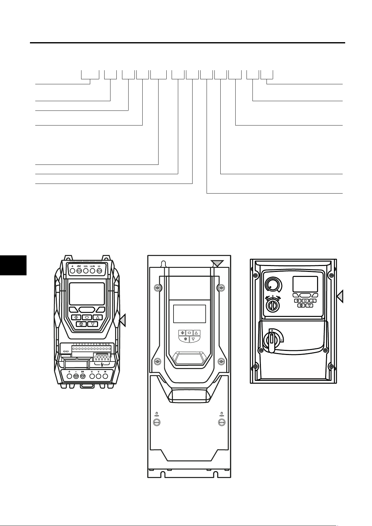
2.1. Identifying the Drive by Model Number
The model number of each Optidrive P2 is constructed according to the following system:
ODP - 2 - 2 4 400 - 3 K F 4 2 - M N
Product Family PCB Coating
General Information & Ratings
Generation Display
Frame Size
Voltage Code
2 : 230 Volt
4 : 400 Volt
5 : 525 Volt
6 : 600 Volt
Three Digit Power Rating
Input Phases Brake Chopper
Power Type
K : kW Rated
H : HP Rated
N : Standard Localised Coating
M: TFT display
T : OLED Text Display
Enclosure
2 : IP20
N : IP55 Non-Switched
A: IP66 Outdoor Non-Switched
B: IP66 Outdoor Switched
4 : Internal Brake Chopper
EMC Filter
0 : No Internal Filer
F : Internal EMC Filter
2
2.2. Product Rating Label Location
All Optidrive P2 models carry a rating label, which can be located as follows:
IP20 Models IP55 Models IP66 Models
On right hand side when viewed from the
front.
On right hand side when viewed from the
front.
On the top surface.
6 | Optidrive P2 User Guide | Version 3.04 www.invertekdrives.com
Page 7
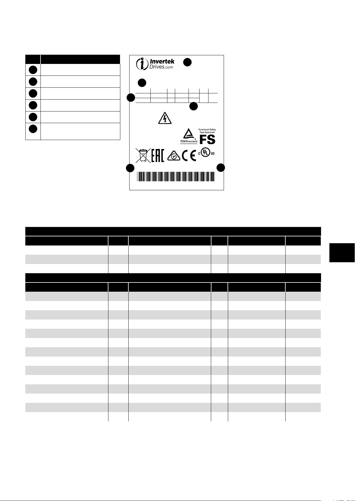
2.3. Understanding the Rating Label
Serial No.:
www.invertekdrives.com
Made in the UK
919011
S/Ware
2.50
HP
/ NEMA 4X
The product rating label provides the following information.
Key
1 Model Code
2 Enclosure Type and IP Rating
3 Firmware Version
4 Serial Number
5 Technical Data – Supply Voltage
Technical Data – Maximum
6
5
OPTIDRIVE P2
ODP-2-64075-3KF42-MN
1
Input
Output
5min before
removing
cover
V
380-480 3 153.2
0-500 150.0
CAUTION
2
20IP
Ø F(Hz) I (A)
50/60
3 0-500
kW
75
6
Read User Guide BeforePower down for
installation or servicing
SCCR: For rating and
protection refer to User Guide
100
continuous output current
Listed 2AD0
Ind.Cont.Eq.
4
11111111111
E226333
3
2.4. Drive Model Numbers – IP20
Mechanical Dimensions and Mounting information are shown in section 3.5.1. IP20 Units on page 13.
Electrical Specifications are shown in section 10.2. Input/Output Power and Current Ratings on page 72.
200-240V ±10% - 1 Phase Input
kW Model kW HP Model HP Output Current (A) Frame Size
ODP-2-22075-1KF42-MN 0.75 ODP-2-22010-1HF42-MN 1 4.3 2
ODP-2-22150-1KF42-MN 1.5 ODP-2-22020-1HF42-MN 2 7 2
ODP-2-22220-1KF42-MN 2.2 ODP-2-22030-1HF42-MN 3 10.5 2
200-240V ±10% - 3 Phase Input
kW Model kW HP Model HP Output Current (A) Frame Size
ODP-2-22075-3KF42-MN 0.75 ODP-2-22010-3HF42-MN 1 4.3 2
ODP-2-22150-3KF42-MN 1.5 ODP-2-22020-3HF42-MN 2 7 2
ODP-2-22220-3KF42-MN 2.2 ODP-2-22030-3HF42-MN 3 10.5 2
ODP-2-32040-3KF42-MN 4 ODP-2-32050-3HF42-MN 5 18 3
ODP-2-32055-3KF42-MN 5.5 ODP-2-32075-3HF42-MN 7. 5 24 3
ODP-2-42075-3KF42-MN 7. 5 ODP-2-42100-3HF42-MN 10 30 4
ODP-2-42110-3KF42-MN 11 ODP-2-42150-3HF42-MN 15 46 4
ODP-2-52150-3KF42-MN 15 ODP-2-52020-3HF42-MN 20 61 5
ODP-2-52185-3KF42-MN 18.5 ODP-2-52025-3HF42-MN 25 72 5
ODP-2-62022-3KF42-MN 22 ODP-2-62030-3HF42-MN 30 90 6A
ODP-2-62030-3KF42-MN 30 ODP-2-62040-3HF42-MN 40 110 6A
ODP-2-62037-3KF42-MN 37 ODP-2-62050-3HF42-MN 50 15 0 6B
ODP-2-62045-3KF42-MN 45 ODP-2-62060-3HF42-MN 60 18 0 6B
ODP-2-62055-3KF42-MN 55 ODP-2-62075-3HF42-MN 75 202 6B
General Information & Ratings
2
Version 3.04 | Optidrive P2 User Guide | 7www.invertekdrives.com
Page 8

380-480V ±10% - 3 Phase Input
kW Model kW HP Model HP Output Current (A) Frame Size
ODP-2-24075-3KF42-MN 0.75 ODP-2-24010-3HF42-MN 1 2.2 2
ODP-2-24150-3KF42-MN 1.5 ODP-2-24020-3HF42-MN 2 4.1 2
ODP-2-24220-3KF42-MN 2.2 ODP-2-24030-3HF42-MN 3 5.8 2
General Information & Ratings
2
ODP-2-24400-3KF42-MN 4 ODP-2-24050-3HF42-MN 5 9.5 2
ODP-2-34055-3KF42-MN 5.5 ODP-2-34075-3HF42-MN 7. 5 14 3
ODP-2-34075-3KF42-MN 7. 5 ODP-2-34100-3HF42-MN 10 18 3
ODP-2-34110-3KF42-MN 11 ODP-2-34150-3HF42-MN 15 24 3
ODP-2-44150-3KF42-MN 15 ODP-2-44200-3HF42-MN 20 30 4
ODP-2-44185-3KF42-MN 18.5 ODP-2-44250-3HF42-MN 25 39 4
ODP-2-44220-3KF42-MN 22 ODP-2-44300-3HF42-MN 30 46 4
ODP-2-54300-3KF42-MN 30 ODP-2-54040-3HF42-MN 40 61 5
ODP-2-54370-3KF42-MN 37 ODP-2-54050-3HF42-MN 50 72 5
ODP-2-64045-3KF42-MN 45 ODP-2-64060-3HF42-MN 60 90 6A
ODP-2-64055-3KF42-MN 55 ODP-2-64075-3HF42-MN 75 11 0 6A
ODP-2-64075-3KF42-MN 75 ODP-2-64100-3HF42-MN 100 15 0 6B
ODP-2-64090-3KF42-MN 90 ODP-2-64150-3HF42-MN 15 0 180 6B
ODP-2-64110-3KF42-MN 11 0 ODP-2-64175-3HF42-MN 175 202 6B
ODP-2-84200-3KF42-MN 200 ODP-2-84300-3HF42-MN 300 370 8
ODP-2-84250-3KF42-MN 250 ODP-2-84400-3HF42-MN 400 450 8
500-600V ±10% - 3 Phase Input
kW Model kW HP Model HP Output Current (A) Frame Size
ODP-2-26075-3K042-MN 0. 75 ODP-2-26010-3H042-MN 1 2 .1 2
ODP-2-26150-3K042-MN 1. 5 ODP-2-26020-3H042-MN 2 3.1 2
ODP-2-26220-3K042-MN 2.2 ODP-2-26030-3H042-MN 3 4.1 2
ODP-2-26400-3K042-MN 4 ODP-2-26050-3H042-MN 5 6.5 2
ODP-2-26550-3K042-MN 5.5 ODP-2-26075-3H042-MN 7. 5 9 2
ODP-2-36075-3K042-MN 7. 5 ODP-2-36100-3H042-MN 10 12 3
ODP-2-36110-3K042-MN 11 ODP-2-36150-3H042-MN 15 17 3
ODP-2-36150-3K042-MN 15 ODP-2-36200-3H042-MN 20 22 3
ODP-2-46185-3K042-MN 18.5 ODP-2-46250-3H042-MN 25 28 4
ODP-2-46220-3K042-MN 22 ODP-2-46300-3H042-MN 30 34 4
ODP-2-46300-3K042-MN 30 ODP-2-46400-3H042-MN 40 43 4
ODP-2-56370-3K042-MN 37 ODP-2-56050-3H042-MN 50 54 5
ODP-2-56045-3K042-MN 45 ODP-2-56060-3H042-MN 60 65 5
ODP-2-66055-3K042-MN 55 ODP-2-66075-3H042-MN 75 78 6A
ODP-2-66075-3K042-MN 75 ODP-2-66100-3H042-MN 10 0 10 5 6A
ODP-2-66090-3K042-MN 90 ODP-2-66125-3H042-MN 12 5 13 0 6B
ODP-2-66110-3K042-MN 110 ODP-2-66150-3H042-MN 15 0 15 0 6B
8 | Optidrive P2 User Guide | Version 3.04 www.invertekdrives.com
Page 9

2.5. Drive Model Numbers – IP55
Mechanical dimensions and mounting information are shown from section 3.5.2. IP55 Units on page 14.
Electrical specifications are shown in section 10.2. Input/Output Power and Current Ratings on page 72.
200-240V ±10% - 3 Phase Input
kW Model Number kW HP Model Number HP Output Current (A) Frame Size
ODP-2-42055-3KF4N-TN 5.5 ODP-2-42075-3HF4N-TN 7. 5 24 4
ODP-2-42075-3KF4N-TN 7. 5 ODP-2-42100-3HF4N-TN 10 30 4
ODP-2-42110-3KF4N-TN 11 ODP-2-42150-3HF4N-TN 15 46 4
ODP-2-52150-3KF4N-TN 15 ODP-2-52020-3HF4N-TN 20 61 5
ODP-2-52185-3KF4N-TN 18.5 ODP-2-52025-3HF4N-TN 25 72 5
ODP-2-62022-3KF4N-TN 22 ODP-2-62030-3HF4N-TN 30 90 6
ODP-2-62030-3KF4N-TN 30 ODP-2-62040-3HF4N-TN 40 11 0 6
ODP-2-62037-3KF4N-TN 37 ODP-2-62050-3HF4N-TN 50 15 0 6
ODP-2-62045-3KF4N-TN 45 ODP-2-62060-3HF4N-TN 60 18 0 6
ODP-2-72055-3KF4N-TN 55 ODP-2-72075-3HF4N-TN 75 202 7
ODP-2-72075-3KF4N-TN 75 ODP-2-72100-3HF4N-TN 10 0 248 7
380-480V ±10% - 3 Phase Input
kW Model Number kW HP Model Number HP Output Current (A) Frame Size
ODP-2-44110-3KF4N-TN 11 ODP-2-44150-3HF4N-TN 15 24 4
ODP-2-44150-3KF4N-TN 15 ODP-2-44200-3HF4N-TN 20 30 4
ODP-2-44185-3KF4N-TN 18.5 ODP-2-44250-3HF4N-TN 25 39 4
ODP-2-44220-3KF4N-TN 22 ODP-2-44300-3HF4N-TN 30 46 4
ODP-2-54300-3KF4N-TN 30 ODP-2-54040-3HF4N-TN 40 61 5
ODP-2-54370-3KF4N-TN 37 ODP-2-54050-3HF4N-TN 50 72 5
ODP-2-64045-3KF4N-TN 45 ODP-2-64060-3HF4N-TN 60 90 6
ODP-2-64055-3KF4N-TN 55 ODP-2-64075-3HF4N-TN 75 110 6
ODP-2-64075-3KF4N-TN 75 ODP-2-64100-3HF4N-TN 10 0 15 0 6
ODP-2-64090-3KF4N-TN 90 ODP-2-64150-3HF4N-TN 15 0 18 0 6
ODP-2-74110-3KF4N-TN 110 ODP-2-74175-3HF4N-TN 175 202 7
ODP-2-74132-3KF4N-TN 13 2 ODP-2-74200-3HF4N-TN 200 240 7
ODP-2-74160-3KF4N-TN 16 0 ODP-2-74250-3HF4N-TN 250 302 7
480-525V ±10% - 3 Phase Input
kW Model Number kW HP Model Number HP Output Current (A) Frame Size
ODP-2-75132-3K04N-TN 13 2 175 185 7
ODP-2-75150-3K04N-TN 15 0 200 205 7
ODP-2-75185-3K04N-TN 18 5 250 255 7
ODP-2-75200-3K04N-TN 200 270 275 7
500-600V ±10% - 3 Phase Input
kW Model Number kW HP Model Number HP Output Current (A) Frame Size
ODP-2-46150-3K04N-TN 15 ODP-2-46200-3H04N-TN 20 22 4
ODP-2-46185-3K04N-TN 18.5 ODP-2-46250-3H04N-TN 25 28 4
ODP-2-46220-3K04N-TN 22 ODP-2-46300-3H04N-TN 30 34 4
ODP-2-46300-3K04N-TN 30 ODP-2-46400-3H04N-TN 40 43 4
ODP-2-56370-3K04N-TN 37 ODP-2-56050-3H04N-TN 50 54 5
ODP-2-56450-3K04N-TN 45 ODP-2-56060-3H04N-TN 60 65 5
ODP-2-66055-3K04N-TN 55 ODP-2-66075-3H04N-TN 75 78 6
ODP-2-66075-3K04N-TN 75 ODP-2-66100-3H04N-TN 10 0 10 5 6
ODP-2-66090-3K04N-TN 90 ODP-2-66125-3H04N-TN 12 5 13 0 6
ODP-2-66110-3K04N-TN 110 ODP-2-66150-3H04N-TN 15 0 15 0 6
General Information & Ratings
2
Version 3.04 | Optidrive P2 User Guide | 9www.invertekdrives.com
Page 10

2.6. Drive Model Numbers – IP66 Non-switched
Mechanical dimensions and mounting information are shown from section 3.5.3. IP66 Units on page 15.
Electrical specifications are shown in section 10.2. Input/Output Power and Current Ratings on page 72.
200-240V ±10% - 1 Phase Input
kW Model Number kW HP Model Number HP Output Current (A) Frame Size
ODP-2-22075-1KF4A-MN 1 ODP-2-22010-1HF4A-MN 1 4.3 2
General Information & Ratings
2
ODP-2-22150-1KF4A-MN 2 ODP-2-22020-1HF4A-MN 2 7 2
ODP-2-22220-1KF4A-MN 3 ODP-2-22030-1HF4A-MN 3 10.5 2
200-240V ±10% - 3 Phase Input
kW Model Number kW HP Model Number HP Output Current (A) Frame Size
ODP-2-22075-3KF4A-MN 0.75 ODP-2-22010-3HF4A-MN 1 4.3 2
ODP-2-22150-3KF4A-MN 1.5 ODP-2-22020-3HF4A-MN 2 7 2
ODP-2-22220-3KF4A-MN 2.2 ODP-2-22030-3HF4A-MN 3 10.5 2
ODP-2-32040-3KF4A-MN 4 ODP-2-32050-3HF4A-MN 5 18 3
ODP-2-32055-3KF4A-MN 5.5 ODP-2-32075-3HF4A-MN 7. 5 24 3
ODP-2-42075-3KF4A-MN 7. 5 ODP-2-42100-3HF4A-MN 10 30 4
ODP-2-42110-3KF4A-MN 11 ODP-2-42150-3HF4A-MN 15 46 4
380-480V ±10% - 3 Phase Input
kW Model Number kW HP Model Number HP Output Current (A) Frame Size
ODP-2-24075-3KF4A-MN 0.75 ODP-2-24010-3HF4A-MN 1 2.2 2
ODP-2-24150-3KF4A-MN 1.5 ODP-2-24020-3HF4A-MN 2 4 .1 2
ODP-2-24220-3KF4A-MN 2.2 ODP-2-24030-3HF4A-MN 3 5.8 2
ODP-2-24400-3KF4A-MN 4 ODP-2-24050-3HF4A-MN 5 9.5 2
ODP-2-34055-3KF4A-MN 5.5 ODP-2-34075-3HF4A-MN 7. 5 14 3
ODP-2-34075-3KF4A-MN 7. 5 ODP-2-34100-3HF4A-MN 10 18 3
ODP-2-34110-3KF4A-MN 11 ODP-2-34150-3HF4A-MN 15 24 3
ODP-2-44150-3KF4A-MN 15 ODP-2-44200-3HF4A-MN 20 30 4
ODP-2-44185-3KF4A-MN 18.5 ODP-2-44250-3HF4A-MN 25 39 4
ODP-2-44220-3KF4A-MN 22 ODP-2-44300-3HF4A-MN 30 46 4
500-600V ±10% - 3 Phase Input
kW Model Number kW HP Model Number HP Output Current (A) Frame Size
ODP-2-26075-3K04A-MN 0 . 75 ODP-2-26010-3H04A-MN 1 2.1 2
ODP-2-26150-3K04A-MN 1.5 ODP-2-26020-3H04A-MN 2 3.1 2
ODP-2-26220-3K04A-MN 2.2 ODP-2-26030-3H04A-MN 3 4.1 2
ODP-2-26400-3K04A-MN 4 ODP-2-26050-3H04A-MN 5 6.5 2
ODP-2-26550-3K04A-MN 5.5 ODP-2-26075-3H04A-MN 7. 5 9 2
ODP-2-36075-3K04A-MN 7. 5 ODP-2-36100-3H04A-MN 10 12 3
ODP-2-36110-3K04A-MN 11 ODP-2-36150-3H04A-MN 15 17 3
ODP-2-36150-3K04A-MN 15 ODP-2-36200-3H04A-MN 20 22 3
ODP-2-46185-3KF4A-MN 18.5 ODP-2-46250-3HF4A-MN 25 28 4
ODP-2-46220-3KF4A-MN 22 ODP-2-46300-3HF4A-MN 30 34 4
ODP-2-46300-3KF4A-MN 30 ODP-2-46400-3HF4A-MN 40 43 4
10 | Optidrive P2 User Guide | Version 3.04 www.invertekdrives.com
Page 11

2.7. Drive Model Numbers – IP66 Switched
Mechanical dimensions and mounting information are shown from section 3.5.3. IP66 Units on page 15.
Electrical specifications are shown in section 10.2. Input/Output Power and Current Ratings on page 72.
200-240V ±10% - 1 Phase Input
kW Model Number kW HP Model Number HP Output Current (A) Frame Size
ODP-2-22075-1KF4B-MN 1 ODP-2-22010-1HF4B-MN 1 4.3 2
ODP-2-22150-1KF4B-MN 2 ODP-2-22020-1HF4B-MN 2 7 2
ODP-2-22220-1KF4B-MN 3 ODP-2-22030-1HF4B-MN 3 10.5 2
200-240V ±10% - 3 Phase Input
kW Model Number kW HP Model Number HP Output Current (A) Frame Size
ODP-2-22075-3KF4B-MN 0. 75 ODP-2-22010-3HF4B-MN 1 4.3 2
ODP-2-22150-3KF4B-MN 1.5 ODP-2-22020-3HF4B-MN 2 7 2
ODP-2-22220-3KF4B-MN 2.2 ODP-2-22030-3HF4B-MN 3 10.5 2
ODP-2-32040-3KF4B-MN 4 ODP-2-32050-3HF4B-MN 5 18 3
ODP-2-32055-3KF4B-MN 5.5 ODP-2-32075-3HF4B-MN 7. 5 24 3
ODP-2-42075-3KF4B-MN 7. 5 ODP-2-42100-3HF4B-MN 10 30 4
ODP-2-42110-3KF4B-MN 11 ODP-2-42150-3HF4B-MN 15 46 4
380-480V ±10% - 3 Phase Input
kW Model Number kW HP Model Number HP Output Current (A) Frame Size
ODP-2-24075-3KF4B-MN 0. 75 ODP-2-24010-3HF4B-MN 1 2.2 2
ODP-2-24150-3KF4B-MN 1.5 ODP-2-24020-3HF4B-MN 2 4 .1 2
ODP-2-24220-3KF4B-MN 2.2 ODP-2-24030-3HF4B-MN 3 5.8 2
ODP-2-24400-3KF4B-MN 4 ODP-2-24050-3HF4B-MN 5 9.5 2
ODP-2-34055-3KF4B-MN 5.5 ODP-2-34075-3HF4B-MN 7. 5 14 3
ODP-2-34075-3KF4B-MN 7. 5 ODP-2-34100-3HF4B-MN 10 18 3
ODP-2-34110-3KF4B-MN 11 ODP-2-34150-3HF4B-MN 15 24 3
ODP-2-44150-3KF4B-MN 15 ODP-2-44200-3HF4B-MN 20 30 4
ODP-2-44185-3KF4B-MN 18.5 ODP-2-44250-3HF4B-MN 25 39 4
ODP-2-44220-3KF4B-MN 22 ODP-2-44300-3HF4B-MN 30 46 4
500-600V ±10% - 3 Phase Input
kW Model Number kW HP Model Number HP Output Current (A) Frame Size
ODP-2-26075-3K04B-MN 0 . 75 ODP-2-26010-3H04B-MN 1 2.1 2
ODP-2-26150-3K04B-MN 1.5 ODP-2-26020-3H04B-MN 2 3.1 2
ODP-2-26220-3K04B-MN 2.2 ODP-2-26030-3H04B-MN 3 4.1 2
ODP-2-26400-3K04B-MN 4 ODP-2-26050-3H04B-MN 5 6.5 2
ODP-2-26550-3K04B-MN 5.5 ODP-2-26075-3H04B-MN 7. 5 9 2
ODP-2-36075-3K04B-MN 7. 5 ODP-2-36100-3H04B-MN 10 12 3
ODP-2-36110-3K04B-MN 11 ODP-2-36150-3H04B-MN 15 17 3
ODP-2-36150-3K04B-MN 15 ODP-2-36200-3H04B-MN 20 22 3
ODP-2-46185-3KF4B-MN 18.5 ODP-2-46250-3HF4B-MN 25 28 4
ODP-2-46220-3KF4B-MN 22 ODP-2-46300-3HF4B-MN 30 34 4
ODP-2-46300-3KF4B-MN 30 ODP-2-46400-3HF4B-MN 40 43 4
General Information & Ratings
2
Version 3.04 | Optidrive P2 User Guide | 11www.invertekdrives.com
Page 12

3. Mechanical Installation
3.1. General
The Optidrive should be mounted in a vertical position only, on a flat, flame resistant, vibration free mounting using the integral
mounting holes or DIN Rail clip (Frame Size 2 only).
Do not mount flammable material close to the Optidrive.
Ensure that the minimum cooling air gaps, as detailed in sections 3.6. Guidelines for Enclosure Mounting (IP20 Units) on page
16, 3.8. Guidelines for Mounting (IP55 Units) on page 17 and 3.9. Guidelines for Mounting (IP66 Units) on page 18
are left clear.
Ensure that the ambient temperature range does not exceed the permissible limits for the Optidrive given in section 10.1. Environmental
on page 72.
Provide suitable clean, moisture and contaminant free cooling air sufficient to fulfil the cooling requirements of the Optidrive.
3.2. Before Installation
Mechanical Installation
Carefully Unpack the Optidrive and check for any signs of damage. Notify the shipper immediately if any exist.
Check the drive rating label to ensure it is of the correct type and power requirements for the application.
To prevent accidental damage always store the Optidrive in its original box until required. Storage should be clean and dry and
within the temperature range –40°C to +60°C.
3.3. UL Compliant Installation
Note the following for UL-compliant installation:
For an up to date list of UL compliant products, please refer to UL listing NMMS.E226333.
The drive can be operated within an ambient temperature range as stated in section
For IP20 units, installation is required in a pollution degree 1 environment.
For IP55 units, installation in a pollution degree 2 environment is permissible.
For IP66 units, installation in a pollution degree 4 environment is permissible.
UL Listed ring terminals / lugs must be used for all bus bar and grounding connections.
Refer to section 10.4. Additional Information for UL Approved Installations on page 75.
10.1. Environmental on page 72
.
3
3.4. Installation Following a Period of Storage
100%
Where the drive has been stored for some time prior to installation,
or has remained without the main power supply present for an
extended period of time, it is necessary to reform the DC capacitors
75%
within the drive according to the following table before operation.
For drives which have not been connected to the main power supply
for a period of more than 2 years, this requires a reduced mains
voltage mains voltage to be applied for a time period, and gradually
50%
increased prior to operating the drive. The voltage levels relative to
the drive rated voltage, and the time periods for which they must be
applied are shown in the following table. Following completion of the
25%
procedure, the drive may be operated as normal.
T1 T2 T3 T4
Storage Period
/Power-OFF
Period
Up to 1 Year 100% N/A
1 – 2 Years 100% 1 Hour N/A
2 – 3 Years 25% 30 Minutes 50% 30 Minutes 75% 30 Minutes 100% 30 Minutes
More than 3 Years 25% 2 Hours 50% 2 Hours 75% 2 Hours 100% 2 Hours
Initial
Input
Voltage
Level
Time
Period T1
Secondary
Input
Voltage
Level
Time
Period T2
Third
Input
Voltage
Level
Time
Period T3
Final
Input
Voltage
Level
Period T4
Time
12 | Optidrive P2 User Guide | Version 3.04 www.invertekdrives.com
Page 13
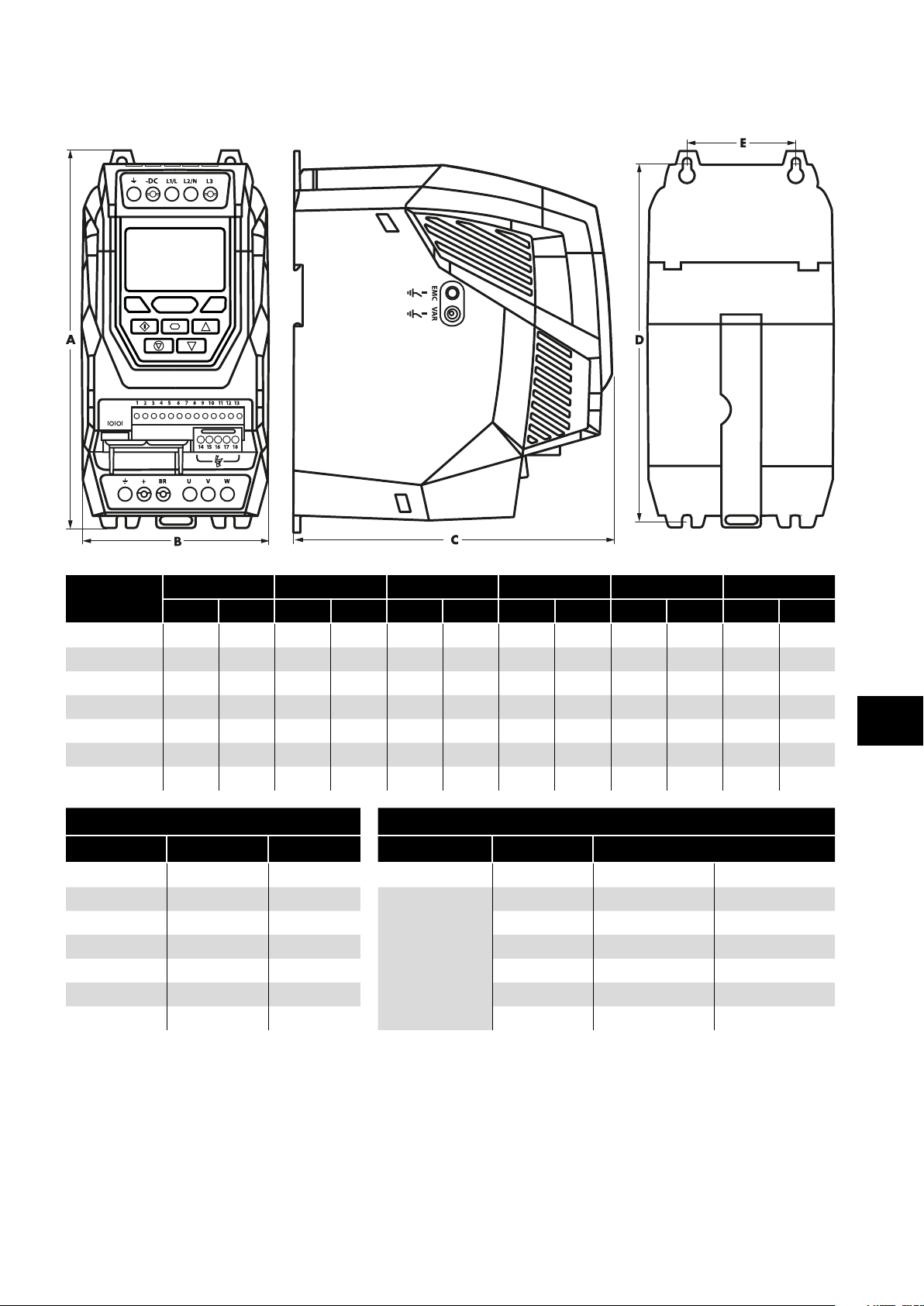
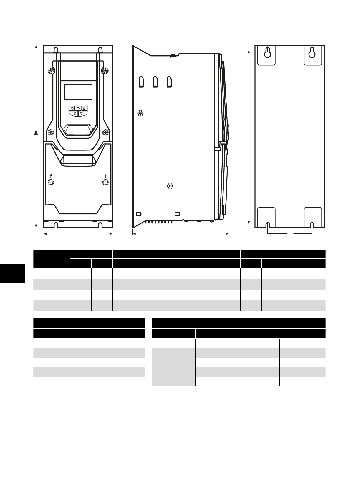
3.5. Mechanical Dimensions and Weight
3.5.1. IP20 Units
Mechanical Installation
Drive Size
2 221 8.70 110 4.33 185 7.28 209 8.23 63 2.48 1.8 4.0
3 2 61 10.28 131 5.16 205 8.07 247 9.72 80 3 .15 3.5 7. 7
4 418 16.46 172 6.77 240 9.45 400 15. 75 125 4.92 9.2 20.3
5 486 19 .13 233 9 .17 260 10.24 460 18.11 175 6.89 18 .1 39.9
6A 614 24.17 286 11 . 25 320 12.59 5 78 22. 75 200 7. 87 32 70.5
6B 726 28.58 330 13 320 12.59 680 26.77 225 8.85 43 94.8
8 995 3 9.17 480 18.89 477 18 .77 942 37.08 432 17 13 0 286.6
Mounting Bolts Tightening Torques
Frame Size Metric UNF Frame Size Required Torque
2 M4 #8 Control Terminals All 0.5 Nm 4.5 lb-in
3 M4 #8
4 M8 5/16 4 2 Nm 18 lb-in
5 M8 5/16 5 4 Nm 35.5 lb-in
6A M8 5/16 6A 12 Nm 9 lb-ft
6B M 10 3/8 6B 15 Nm 11 lb-ft
8 M 12 7/16 8 57 Nm 42 lb-ft
A B C D E Weight
mm in mm in mm in mm in mm in Kg Ib
2 & 3 1 Nm 9 lb-in
Power Terminals
3
NOTE
*The IP20 Frame Size 4 Chassis can obstruct the rotation (tightening) of a bolt or screw with a hex head, a fixing with a round head
will be most suitable for the mounting of this unit.
Version 3.04 | Optidrive P2 User Guide | 13www.invertekdrives.com
Page 14
3.5.2. IP55 Units
B
Mechanical Installation
D
3
C
Drive Size
4 450 17. 72 171 6 . 73 252 9.92 428 16.85 110 4.33 11 . 5 25.4
5 540 21.26 235 9.25 270 10.63 515 20.28 175 6.89 23 50.7
6 865 34.06 330 12.99 330 12.99 830 32.68 200 7. 87 55 121. 2
7 1280 50.39 330 12.99 360 14 .17 124 5 49.02 200 7. 87 89
Mounting Bolts Tightening Torques
Frame Size Metric UNF Frame Size Required Torque
4 M8 5/16
5 M8 5/16
6 M10 3/8
7 M10 3/8
A B C D E Weight
mm in mm in mm in mm in mm in kg Ib
Control Terminals All 0.5 Nm 4.5 lb-in
4 2 Nm 18 lb-in
Power Terminals
5 4 Nm 35.5 lb-in
6 15 Nm 11 lb-ft
7 15 Nm 11 lb-ft
E
196.2
14 | Optidrive P2 User Guide | Version 3.04 www.invertekdrives.com
Page 15
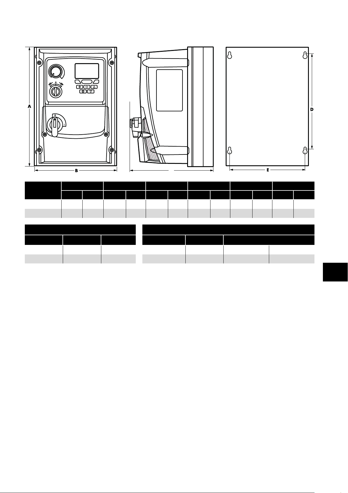
3.5.3. IP66 Units
C
Mechanical Installation
Drive Size
2 257 10 .12 188 7.40 239 9 . 41 200 7. 87 178 7. 01 4.8 10.6
3 310 12.20 211 8.29 266 10.47 252
Mounting Bolts Tightening Torques
Frame Size Metric UNF Frame Size Required Torque
2 M4 #8 Control Terminals All 0.5 Nm 4.5 lb-in
3 M4 #8 Power Terminals 2 & 3 1 Nm 9 lb-in
A B C D E Weight
mm in mm in mm in mm in mm in kg Ib
9.90
200 7. 87 7. 7 16.8
3
Version 3.04 | Optidrive P2 User Guide | 15www.invertekdrives.com
Page 16
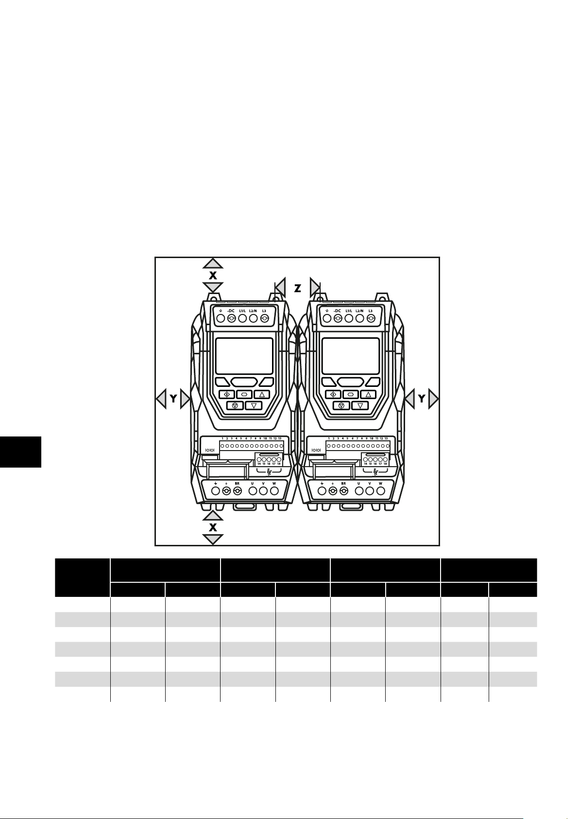
3.6. Guidelines for Enclosure Mounting (IP20 Units)
IP20 drives are suitable for use in pollution degree 1 environments, according to IEC-664-1. For pollution degree 2 or higher
environments, drives should be mounted in a suitable control cabinet with sufficient ingress protection to maintain a pollution
degree 1 environment around the drive.
Enclosures should be made from a thermally conductive material.
Ensure the minimum air gap clearances around the drive as shown below are observed when mounting the drive.
Where ventilated enclosures are used, there should be venting above the drive and below the drive to ensure good air circulation.
Air should be drawn in below the drive and expelled above the drive.
In any environments where the conditions require it, the enclosure must be designed to protect the Optidrive against ingress of
airborne dust, corrosive gases or liquids, conductive contaminants (such as condensation, carbon dust, and metallic particles) and
sprays or splashing water from all directions.
High moisture, salt or chemical content environments should use a suitably sealed (non-vented) enclosure.
The enclosure design and layout should ensure that the adequate ventilation paths and clearances are left to allow air to circulate
through the drive heatsink. Invertek Drives recommend the following minimum sizes for drives mounted in non-ventilated metallic
Mechanical Installation
enclosures:
3
X
Drive Size
2 75 2.95 10 0.39 46 1. 81 0.3 11
3 100 3.94 10 0.39 52 2.05 0.9 31
4 200 7. 87 25 0.98 70 2 . 76 1. 7 62
5 200 7. 87 25 0.98 70 2 . 76 2.9 104
6A 200 7. 87 25 0.98 70 2 . 76
6B 200 7. 87 25 0.98 70 2.76
8 350 11 . 81 50 3.94 412 16.22 20 705
Above & Below
mm in mm in mm in m3/min CFM
Y
Either Side
Z
Between
Recommended
NOTE
Dimension Z assumes that the drives are mounted side-by-side with no clearance.
Typical drive heat losses are <3% of operating load conditions.
Above are guidelines only and the operating ambient temperature of the drive MUST be maintained at all times.
airflow
16 | Optidrive P2 User Guide | Version 3.04 www.invertekdrives.com
Page 17
3.7. Mounting the Drive – IP20 Units
IP20 Units are intended for installation within a control cabinet.
When mounting with screws:
o Using the drive as a template, or the dimensions shown above, mark the locations for drilling.
o Ensure that when mounting locations are drilled, the dust from drilling does not enter the drive.
o Mount the drive to the cabinet backplate using suitable mounting screws.
o Position the drive, and tighten the mounting screws securely.
When Din Rail Mounting (Frame Size 2 Only):
o Locate the DIN rail mounting slot on the rear of the drive onto the top of the DIN rail first.
o Press the bottom of the drive onto the DIN rail until the lower clip attaches to the DIN rail.
o If necessary, use a suitable flat blade screw driver to pull the DIN rail clip down to allow the drive to mount securely on the rail.
o To remove the drive from the DIN rail, use a suitable flat blade screwdriver to pull the release tab downwards, and lift the
bottom of the drive away from the rail first.
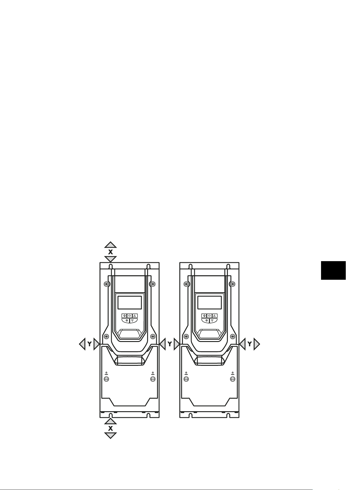
3.8. Guidelines for Mounting (IP55 Units)
Before mounting the drive, ensure that the chosen location meets the environmental condition requirements for the drive shown in
section 10.1. Environmental on page 72.
The drive must be mounted vertically, on a suitable flat surface.
The minimum mounting clearances as shown in the table below must be observed.
The mounting site and chosen mountings should be sufficient to support the weight of the drives.
IP55 units do not require mounting inside an electrical control cabinet; however they may be if desired.
Using the drive as a template, or the dimensions shown above, mark the locations required for drilling.
Suitable cable glands to maintain the IP protection of the drive are required. Gland sizes should be selected based on the number
and size of the required connection cables. Drives are supplied with a plain, undrilled gland plate to allow the correct hole sizes to
be cut as required. Remove the gland plate from the drive prior to drilling.
Mechanical Installation
3
Version 3.04 | Optidrive P2 User Guide | 17www.invertekdrives.com
Page 18
Drive Size
4 200 7. 87 10 0.39
5 200 7. 87 10 0.39
6 200 7. 87 10 0.39
7 200 7. 87 10 0.39
NOTE
Typical drive heat losses are approximately 3% of operating load conditions.
Above are guidelines only and the operating ambient temperature of the drive MUST be maintained at all times.
3.9. Guidelines for Mounting (IP66 Units)
Before mounting the drive, ensure that the chosen location meets the environmental condition requirements for the drive shown in
section 10.1. Environmental on page 72.
Mechanical Installation
The drive must be mounted vertically, on a suitable flat surface.
The minimum mounting clearances as shown in the table below must be observed.
The mounting site and chosen mountings should be sufficient to support the weight of the drives.
Using the drive as a template, or the dimensions shown below, mark the locations required for drilling.
Suitable cable glands to maintain the ingress protection of the drive are required. Gland holes for power and motor cables are
pre-moulded into the drive enclosure, recommended gland sizes are shown below. Gland holes for control cables may be cut as
required.
X –Above & Below Y –Either Side
mm in mm in
3
Drive
Size
2 & 3 200 7. 87 2 & 3 PG21 (M25) PG21 (M25) PG13.5 (M20)
NOTE
Typical drive heat losses are approximately 3% of operating load conditions.
Above are guidelines only and the operating ambient temperature of the drive MUST be maintained at all times.
Alternative metric gland sizes are shown in the brackets.
X
Above & Below
mm in Frame Power Cable Motor Cable Control Cables
Cable Gland Sizes
18 | Optidrive P2 User Guide | Version 3.04 www.invertekdrives.com
Page 19
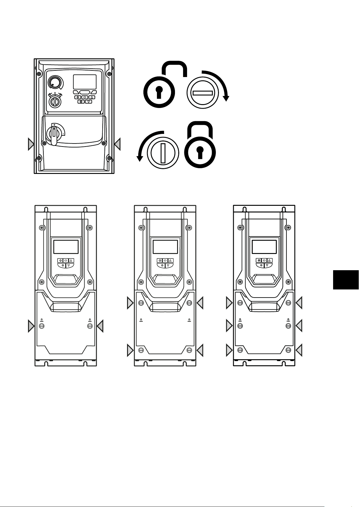
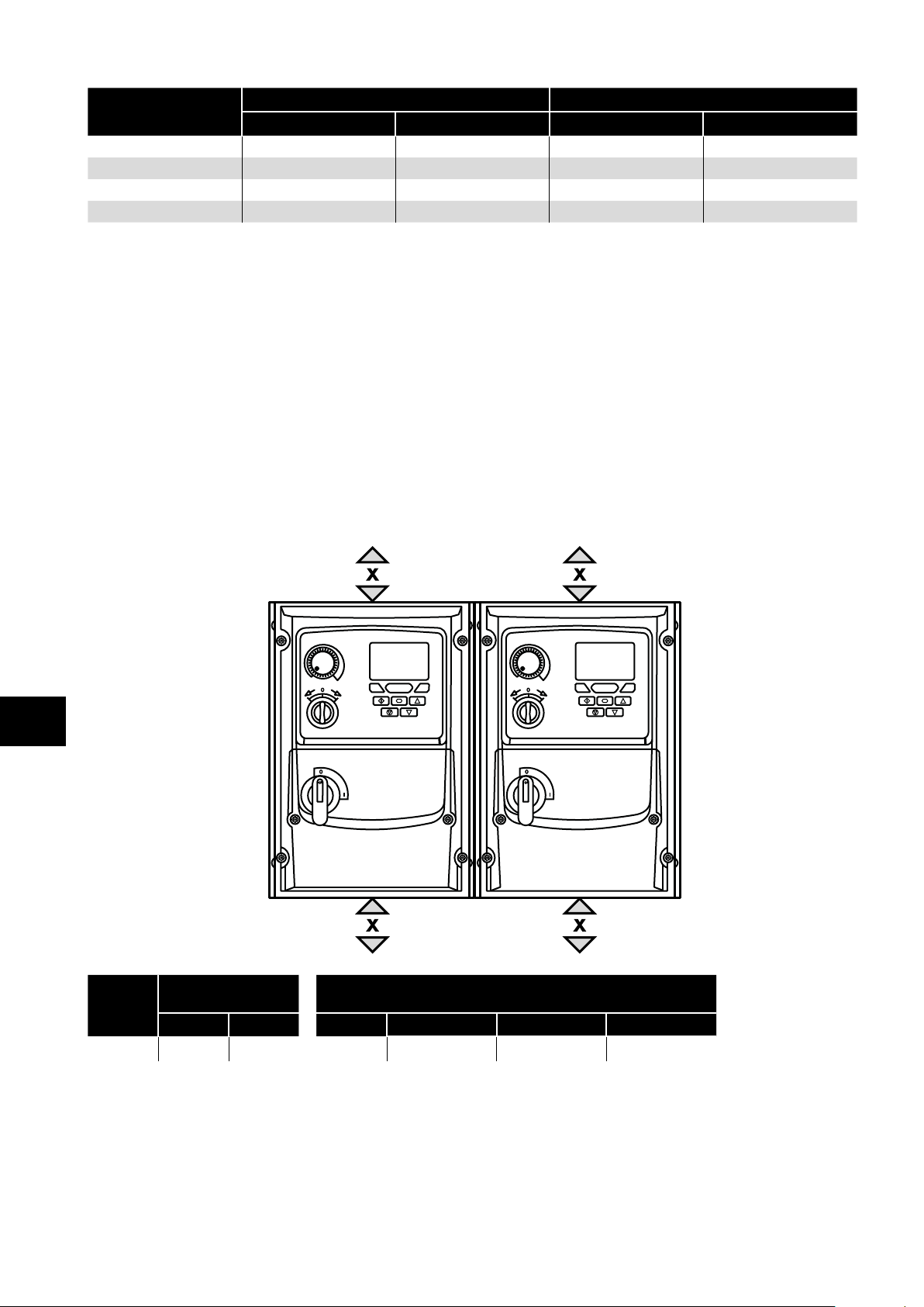
3.10. Removing the Terminal Cover
3.10.1. Frame Sizes 2 & 3
Terminal Cover
Release Screws
Using a suitable flat blade
screwdriver, rotate retaining
screws indicated by arrows until
the screw slot is vertical.
3.10.2. Frame Size 4 3.10.3. Frame Size 5 3.10.4. Frame Sizes 6 & 7
Mechanical Installation
3.11. Routine Maintenance
The drive should be included within the scheduled maintenance program so that the installation maintains a suitable operating
environment, this should include:
Ambient temperature is at or below that set out in section 10.1. Environmental on page 72.
Heat sink fans freely rotating and dust free.
The Enclosure in which the drive is installed should be free from dust and condensation; furthermore ventilation fans and air filters
should be checked for correct air flow.
Checks should also be made on all electrical connections, ensuring screw terminals are correctly torqued; and that power cables
have no signs of heat damage.
3
Version 3.04 | Optidrive P2 User Guide | 19www.invertekdrives.com
Page 20
4. Electrical Installation
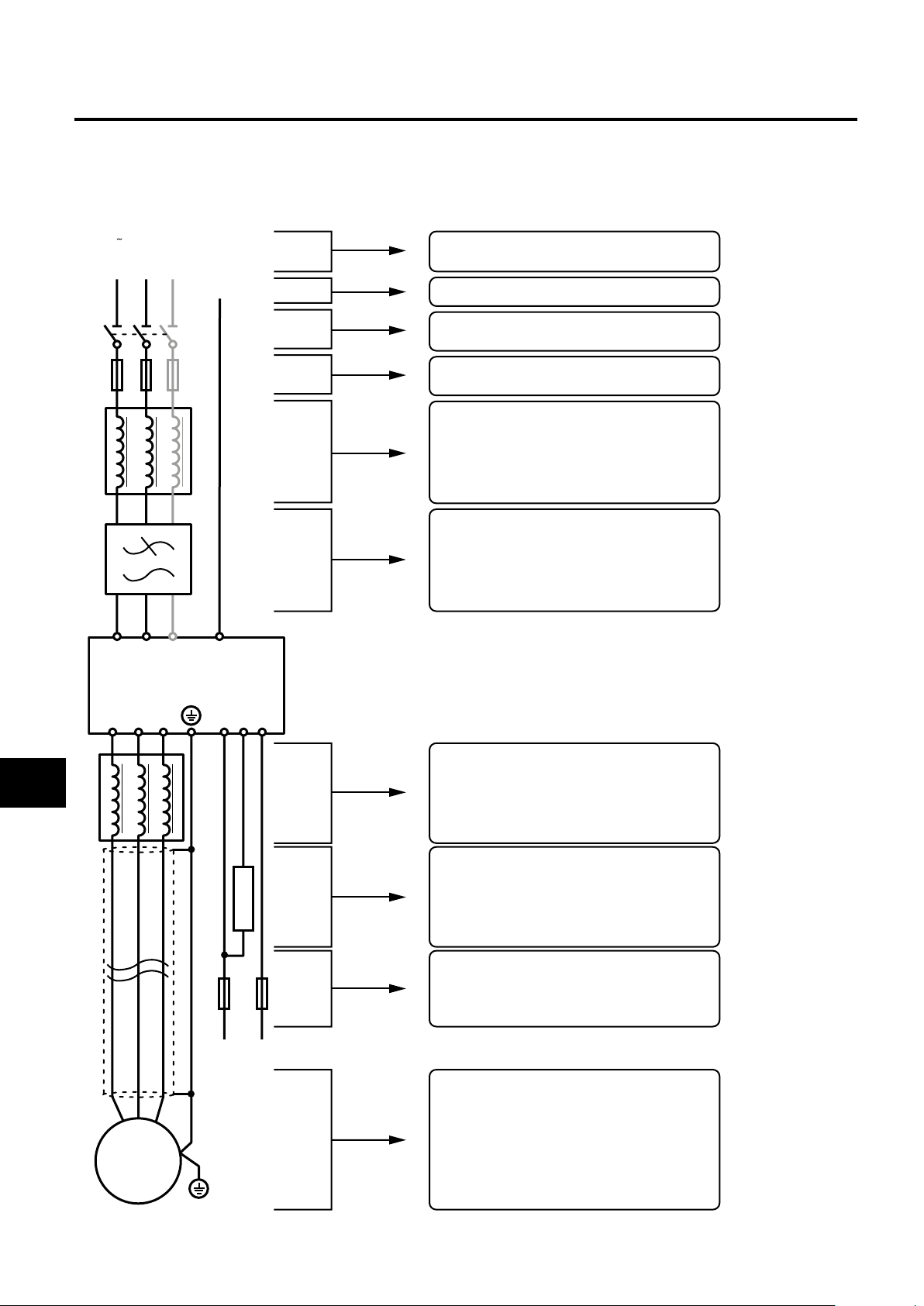
4.1. Connection Diagram
All power terminal locations are marked directly on the product. IP20 Frame Size 2 – 4 units have AC power input located at the top
with the motor and brake resistor connections located at the bottom. All other units have power terminals located at the bottom.
4.1.1. Electrical Power Connections
Mains (1 or 3 phase)
L1/L L2/N L3
PE
Electrical Installation
L1/L L2/N L3
ODP-2
U V W
DC
Additional information in section 4.3. on page 22
Additional information in section 4.2. on page 21
Additional information in section 4.3.3. on page 22
Additional information in section 4.3.4. on page 23
Additional information in section 4.13 . on page 28
DC
-
+
BR
Incoming Power Connection
Protective Earth PE Connection
Isolator/Disconnect
Ensure there is at least 30 seconds
between each power-on!
Fuses/Circuit Breaker
External Line Reactor
NOTE An input choke must be installed
with the IP20 Frame Size 8.
External EMC Filter (optional)
4
VI
UI
M
External Output Filter (optional)
Output Choke (load reactor)
dV/dT filter
Sinewave filter
Brake Resistor with Thermal Overload Protection
Additional information in section 4.8. on page 24
DC Power Supply or Common Bus DC
Additional information in section 4.5. on page 23
DC+ DC-
WI
PE
Shielded Motor Cable with PE Connection
Additional information in section 4.6. on page 23
NOTE Enclosed drives are not suitable for rigid conduit system connection.
20 | Optidrive P2 User Guide | Version 3.04 www.invertekdrives.com
Page 21
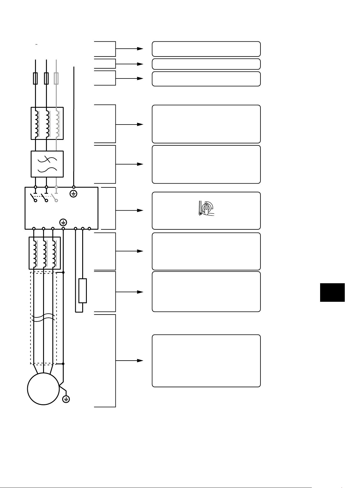
4.1.2. Electrical Power Connections – IP66 (NEMA 4X) Switched Models
Mains (1 or 3 phase)
L1/L L2/N L3
Additional information in section 4.3. on page 22
PE
Additional information in section 4.2. on page 22
Incoming Power Connection
Protective Earth PE Connection
L1/L L2/N L3
ODP-2 IP66 (NEMA 4X) Switched
U V W
DC
+
Additional information in section 4.3.3. on page 22
Additional information in section 4.3.4. on page 24
Additional information in section 4.13 . on page 28
Fuses/Circuit Breaker
External Line Reactor (optional)
External EMC Filter (optional)
Electrical Installation
Built-in mains switch-disconnector
DC
BR
-
Ensure there is at least 30 seconds
between each power-on!
External Output Filter (optional)
Output Choke (load reactor)
dV/dT filter
Sinewave filter
VI
UI
M
Brake Resistor with Thermal Overload Protection
Additional information in section 4.8. on page 24
Shielded Motor Cable with PE Connection
Additional information in section 4.6. on page 23
WI
PE
4
Version 3.04 | Optidrive P2 User Guide | 21www.invertekdrives.com
Page 22

4.2. Protective Earth (PE) Connection
4.2.1. Grounding Guidelines
Adequate safety earthing must be provided in accordance with local wiring rules and codes of practice. The ground terminal of
each Optidrive should be connected back to the common safety earth bar to maintain touch potentials within safe limits. The ground
terminal of each Optidrive should be individually connected DIRECTLY to the site ground bus bar (through the EMC filter if installed).
Optidrive ground connections should not loop from one drive to another, or to, or from any other equipment. Ground impedance must
conform to local industrial safety regulations and/or electrical codes.
To meet UL regulations, UL approved ring crimp terminals should be used for all ground wiring connections.
The integrity of all ground connections should be checked periodically.
4.2.2. Protective Earth Conductor
The Cross sectional area of the PE Conductor must be at least equal to that of the incoming supply conductors.
4.2.3. Motor Ground
The driven motor must be locally connected to a suitable ground location to maintain touch potentials within safe limits. In addition, the
motor ground must be connected to one of the ground terminals on the drive.
4.2.4. Ground Fault Monitoring
As with all inverters, a leakage current to earth can exist. The Optidrive is designed to produce the minimum possible leakage current
whilst complying with worldwide standards. The level of current is affected by motor cable length and type, the effective switching
frequency, the earth connections used and the type of RFI filter installed. If an ELCB (Earth Leakage Circuit Breaker) is to be used, the
following conditions apply:
A Type B Device must be used.
Electrical Installation
Individual device should be used for each Optidrive.
The device must be suitable for protecting equipment with a DC component in the leakage current.
The device should be not sensitive to high frequency leakage current.
4.2.5. Shield Termination (Cable Screen)
The safety ground terminal provides a grounding point for the motor cable shield. The motor cable shield connected to this terminal
(drive end) should also be connected to the motor frame (motor end). Use a shield terminating or EMI clamp to connect the shield to
the safety ground terminal, refer to section 4.13. EMC Compliant Installation on page 28.
4
4.3. Incoming Power Connection
NOTE For IP20 Frame Size 8 it is important that the input supply phase orientation is correct, i.e. L1>L1, L2>L2, L3>L3, failure to do so
will result in a “Ph-Seq" trip.
Ensure there is at least 30 seconds between each power-on.
4.3.1. Suitability
All Optidrive P2 models are designed for use on a single phase or balanced three phase supply depending on the model.
For all models and ratings when working with an IT Supply network, or any power supply type where the phase to earth voltage may
exceed the phase to phase voltage (such as ungrounded supplies), the internal EMC filter and surge protection must be disconnected before
connecting the supply. Refer to section 10.6. Internal EMC Filter and Varistors – Disconnection Procedure on page 76 for further information.
For three phase supply models, a maximum of 3% imbalance is allowed between phases.
4.3.2. Cable Selection
For 1 phase ac supply, power should be connected to L1/L, L2/N.
For a DC Supply, the main power cables should be connected to L1/L, L2/N.
For 3 phase ac supplies, the mains power cables should be connected to L1, L2, and L3. Phase sequence is not important. Neutral
connection is not required.
For compliance with CE and C Tick EMC requirements, refer to section 4.13. EMC Compliant Installation on page 28.
A fixed installation is required according to IEC61800-5-1 with a suitable disconnecting device installed between the Optidrive
and the main Power Source. The disconnecting device must conform to the local safety code / regulations (e.g. within Europe,
EN60204-1, Safety of machinery).
The cables should be dimensioned according to any local codes or regulations. Maximum dimensions for each drive model are
given in section 10.2. Input/Output Power and Current Ratings on page 72.
4.3.3. Fuse / Circuit Breaker Selection
Suitable fuses to provide wiring protection of the input power cable should be installed in the incoming supply line, according to
the data in section 10.2. Input/Output Power and Current Ratings on page 72.
The fuses must comply with any local codes or regulations in place. In general, type gG (IEC 60269) or UL type J fuses are
suitable (exception: Eaton Bussmann FWP series must be used for size 6A & 6B IP20 models); however in some cases type aR
fuses may be required. The operating time of the fuses must be below 0.5 seconds.
Where allowed by local regulations, suitably dimensioned type B MCB circuit breakers of equivalent rating may be utilised in
place of fuses, providing that the clearing capacity is sufficient for the installation.
The maximum permissible short circuit current at the Optidrive Power terminals as defined in IEC60439-1 is 100kA.
The Optidrive provides thermal and short circuit protection for the connected motor and motor cable.
22 | Optidrive P2 User Guide | Version 3.04 www.invertekdrives.com
Page 23

4.3.4. Input Choke
An optional Input Choke is recommended to be installed in the supply line for drives where any of the following conditions occur:
The incoming supply impedance is low or the fault level / short circuit current is high.
NOTE For IP20 Frame Size 8 the input current level will vary according to supply impedance. At minimum a 1% line choke must be
installed. Installing a 4% line choke further helps towards minimising harmonic current distortion and total current levels. 1% and 4% line
chokes are available.
The supply is prone to dips or brown outs.
An unbalanced supply system is used (3 phase drives) where the voltage levels during on load operation exceed the designed 3%
capacity of the Optidrive.
The power supply to the drive is via a busbar and brush gear system (typically overhead Cranes).
In all other installations, an input choke is recommended to ensure protection of the drive against power supply faults.
4.4. Operation of 3 Phase drives from a Single Phase Supply
A special function of Optidrive P2 allows all drives designed for operation on 3 phase supplies to be operated on a single phase
supply of the correct rated voltage at up to 50% of the nominal capacity.
For Example, Model Number ODP-2-64450-3KA4N can be operated on a single phase supply, 380 – 480 volts, with the
maximum output current limited to 45 Amps.
The supply must be connected to the L1 and L2 terminals of the drive.
4.5. Operation with DC Power Supply or Common DC Bus
Optidrive P2 models provide terminals to directly connect to the DC Bus for applications which require this. For further information on
using the DC Bus connections, please refer to your Invertek Drives sales Partner.
4.6. Motor Connection
The drive inherently produces fast switching of the output voltage (PWM) to the motor compared with operation of the motor
directly from the mains supply. Most modern industrial motors are wound for operation with a variable speed drive and will have
insulation rated accordingly. However, on some motors the quality of insulation may be insufficient or unknown. In such cases the
motor manufacturer should be consulted and preventative measures may be required prior to operating with the drive.
The motor should be connected to the Optidrive U, V, and W terminals using a suitable 3 or 4 core cable. Where a 3 core cable
is utilised, with the shield operating as an earth conductor, the shield must have a cross sectional area at least equal to the phase
conductors when they are made from the same material. Where a 4 core cable is utilised, the earth conductor must be of at least
equal cross sectional area and manufactured from the same material as the phase conductors.
Automatic switchgear should not be installed between the drive output and the motor, opening and closing contacts in this circuit
whilst the drive is energised will inevitably reduce the lifetime of the drive and could cause product failure. If an isolator is required
to be placed between the drive and the motor in order to comply with local regulations, the device must not be operated when the
drive is running.
For compliance with the European EMC directive, a suitable screened (shielded) cable should be used. Braided or twisted type
screened cable where the screen covers at least 85% of the cable surface area, designed with low impedance to HF signals are
recommended as a minimum. Installation within a suitable steel or copper tube is generally also acceptable.
The motor earth must be connected to one of the Optidrive earth terminals to provide a low impedance path for common mode
leakage current to return to the drive. This is best achieved in practice by using a cable with suitable shielding which provides a low
impedance path at high frequencies, and ensuring correct, low impedance earth bonding of the motor cable at both ends. For further
information, refer to section 4.13. EMC Compliant Installation on page 28.
4.7. Motor Terminal Box Connections
Most general purpose motors are wound for operation on dual voltage supplies. This is indicated on the nameplate of the motor. This
operational voltage is normally selected when installing the motor by selecting either STAR or DELTA connection. STAR always gives
the higher of the two voltage ratings.
Incoming Supply Voltage Motor Nameplate Voltages Connection
Electrical Installation
4
230 230 / 400
400 / 460 400 / 690
575 575 / 1000
400 230 / 400
575 330 / 575
Delta
∆
Star
⅄
Version 3.04 | Optidrive P2 User Guide | 23www.invertekdrives.com
Page 24
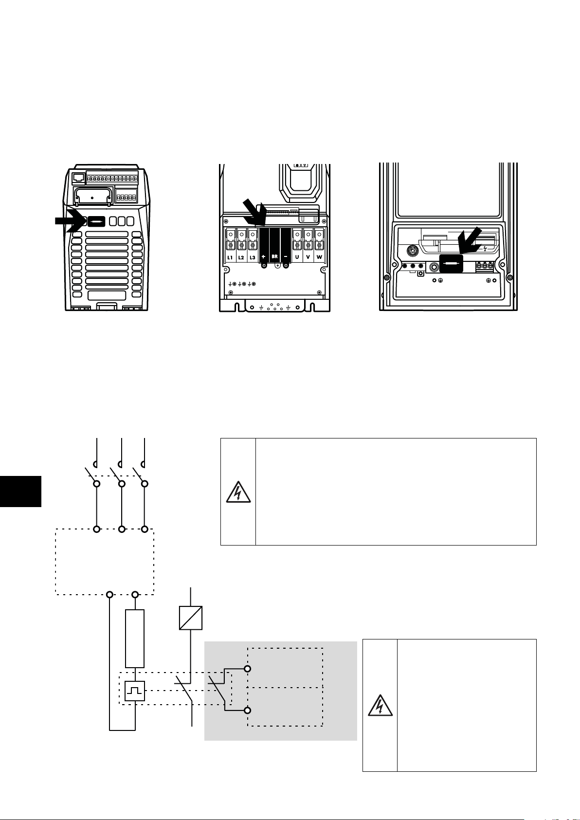
4.8. Connecting a Brake Resistor
Optidrive P2 units feature an internal brake transistor, fitted as standard for all models. The brake resistor should be connected to the
DC+ and BR terminals of the drive. These terminals are shrouded, and the shrouding should be removed to access the terminals.
4.8.1. IP20 Drive Models 4.8.2. IP55 & IP66
Frame Sizes 2, 3, 4 & 5
Remove the plastic cover from the base
of the drive as indicated.
Electrical Installation
The brake transistor is enabled using P1-05 (Refer to section 6.2. Parameter Group 1 – Basic Parameters on page 37 for further
information).
Software protection against brake resistor overload is carried out within the drive. For correct protection of the brake resistor, the
following settings are required:
Set P1-14 = 201 (where 201 is the default password setting for advanced parameter access).
Enter the resistance of the brake resistor in P6-19 (Ohms).
Enter the power of the brake resistor in P6-20 (kW).
Dynamic Brake Resistor with Thermal Overload Protection
Frame Sizes 6A/ 6B
Remove the plastic cover from inside the
drive as indicated.
EMC EMC VAR
AC DC
All frame sizes
Remove the plastic cover from inside the
drive as indicated.
1 2 3 4 5 6 7 8 9
I0I0II0I0I
EMC
L3
L2/N
L1
10 11 12 13
14 15 16 17 18
UVW
4
K1
ODP-2
L2/N L3
L1/L
BR
DC+
K1 - Main Contractor
Thermal Overload / Brake Resistor
with internal Over Temperature switch
It is highly recommended to equip the drive with a main
contactor in order to provide an additional thermal overload
protection for the braking resistor.
The contactor should be wired so that it will open when the
resistor overheats, otherwise the drive will not be able to
interrupt the main supply if the brake chopper remains closed
(short-circuited) in a fault situation.
It is also recommended to wire the thermal overload
protection to a digital input of the drive as an External Trip.
ODP-2
+ 24 VDC
The voltage level at these
terminals may exceed
800V DC.
Stored charge may be
present after disconnecting
Dlx
the mains power.
Allow a minimum of 5
Optional wiring
minutes discharge after
power off before attempting
any connection to these
terminals.
24 | Optidrive P2 User Guide | Version 3.04 www.invertekdrives.com
Page 25

4.9. Control Terminal Wiring
0/4-20 mA
20-4/0 mA
0/4-20 mA
20-4/0 mA
* Dashed lines shows connection for analog inputs in digital mode ** Optional external 24 V DC power supply
All analog signal cables should be suitably shielded. Twisted pair cables are recommended.
Power and Control Signal cables should be routed separately where possible, and must not be routed parallel to each other.
Signal levels of different voltages e.g. 24 Volt DC and 110 Volt AC, should not be routed in the same cable.
Maximum control terminal tightening torque is 0.5Nm.
Control Cable entry conductor size: 0.05 – 2.5mm
4.9.1. Control Connections
2
/ 30 – 12 AWG.
1 (+24V DC/ 100mA)
(AO 1) 8
0-10V
10-0V
+
_
-10 ...10 V
0/4-20 mA
-10 ...10 V
0/4-20 mA
+24 V DC**
0-10 V
10-0 V
20-4 mA
0-10 V
10-0 V
20-4 mA
2 (Dl 1)
3 (Dl 2)
4 (Dl 3)
5 (+10V DC/ 10mA)
6 (AI 1/ DI 4*)
7 (0V/ COM)
10 (AI 2/ DI 5*)
12 (STO+)
13 (STO-)
(0V/ COM) 9
(AO 2) 11
14 (RL1-C)
15 (RL1-NO)
16 (RL1-NC)
17 (RL2-A)
18 (RL2-B)
0-10V
10-0V
NOTE
Key
1 +24V DC 24 Volt DC Input / Output
On-board +24V DC Supply (100mA)
Default Function
Open Closed
or External 24V DC Input
Sec.
Page
4.10 .1 26
2 DI 1 Digital Input 1 (Run Enable) STOP RUN 4.10.2 26
3 DI 2 Digital Input 2 FORWARD REVERSE 4.10.2 26
4 DI 3 Digital Input 3
5 +10V DC +10Volt DC Output On-board +10V DC Supply (10 mA)
P1-12 Reference Preset Speeds 4.10.2 26
6 AI 1 / DI 4 Analog Input 1 / Digital Input 4 Speed Reference 1 (0-10V) 4.10.3 26
7 0V / COM 0 Volt Common 0V Common for AI/AO/DI/DO
8 AO 1 Analog Output 1 Motor Speed (0-10V) 4.10.4 26
9 0V / COM 0 Volt Common 0V Common for AI/AO/DI/DO
10 AI 2 / DI 5 Analog Input 2 / Digital Input 5 P2-01 Speed Ref. P2-02 Speed Ref. 4.10.3 26
11 AO2 Analog Output 2 Motor Current (0-10V) 4.10.4 26
12
13 STO- STO 0 Volt Connection
STO+ STO + 24V DC Connection
InHibit Run Permit 4 .14 29
14 RL1-COM Auxiliary Relay Output 1 Common 4.10.5 26
15 RL1-NO
16 RL1-NC
17 RL2-A Auxiliary Relay Output 2
18 RL2-B Auxiliary Relay Output 2 4.10.5 26
Auxiliary Relay Output 1 Normally Open Drive Healthy Drive Faulty
Auxiliary Relay Output 2 Normally Closed Drive Faulty Drive Healthy
Drive Stopped Drive Running
4.10.5 26
4.10.5 26
4.10.5 26
Electrical Installation
4
NOTE Digital Inputs: Logic High = 8-30V DC (30V DC max) Analog Outputs: 0 – 10 Volt / 4-20mA (20mA max)
SAFE TORQUE OFF input: Logic High = 18-30V DC (Also refer to section 4.14. Safe Torque Off)
Version 3.04 | Optidrive P2 User Guide | 25www.invertekdrives.com
Page 26
4.10. Control Terminal Connections
0/4-20 mA
0/4-20 mA
Example connection schematics are provided in section 7.3. Example Connection Schematics on page 43.
4.10.1. +24V DC Input / Output
When the mains power is applied to the drive, terminal 1 provides a +24V DC output, maximum load 100mA. This may be used to
activate digital inputs or provide power to sensors.
When no mains power is applied to the drive, the drive control electronics may be powered from an external +24V DC source. When
powered in this way, all analog and digital I/O and communication functions remain operative, however the motor may not be
operated, which allows safe testing and commissioning of the installation without risk of high voltage being present. When powered in
this way, the drive requires up to 100mA.
4.10.2. Digital Inputs
Up to five digital inputs are available. The function of the inputs is defined by parameters P1-12 and P1-13, which are explained in
section 7. Control Terminal Functions on page 40.
4.10.3. Analog Inputs
Two analog inputs are available, which may also be used as digital Inputs if required. The signal formats are selected by parameters
as follows:
Analog Input 1 Format Selection Parameter P2-30.
Analog Input 2 Format Selection Parameter P2-33.
These parameters are described more fully in section 8.1. Parameter Group 2 - Extended Parameters on page 47.
Electrical Installation
The function of the analog input, e.g. for speed reference or PID feedback for example is defined by parameters P1-12 and P1-13.
The function of these parameters and available options are described in section 7. Control Terminal Functions on page 40.
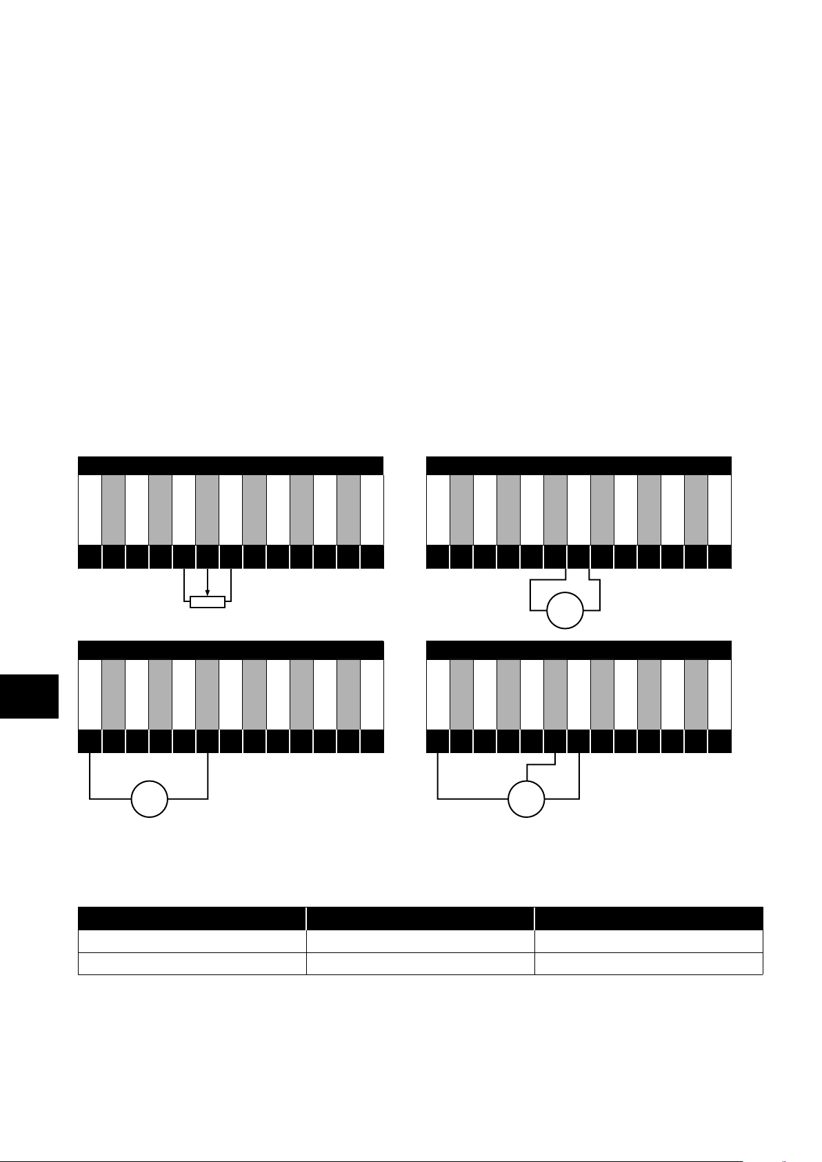
Local Potentiometer Connection - AI1 2-wire Analog Voltage or Current signal
4
+24V DC
1
DI 1
2
DI 2
3
DI 3
4
+10V DC
5
AI 1
6
0V / COM
7
0V / COM
9
DI 5
10
AO 2
11
AO 1
8
STO+
12
STO-
13
+24V DC
1
DI 1
2
DI 2
3
0-10 V
10-0 V
-10-10V
20-4 mA
DI 3
4
+10V DC
5
+
V/A
AI 1
6
0V / COM
7
-
0V / COM
9
DI 5
10
AO 2
11
AO 1
8
STO+
12
STO-
13
2-wire or Loop Powered Transducer 3-wire Transducer
+24V DC
1
DI 1
2
+
0/4-20 mA
DI 2
3
24V DC
Sensor
DI 3
4
-
+10V DC
5
AI 1
6
0V / COM
7
0V / COM
9
DI 5
10
AO 2
11
AO 1
8
STO+
12
STO-
13
+24V DC
1
DI 1
2
DI 2
3
+
DI 3
4
24V DC
Sensor
+10V DC
5
-
AI 1
6
0V / COM
7
0V / COM
9
DI 5
10
AO 2
11
AO 1
8
STO+
12
STO-
13
4.10.4. Analog Outputs
Two analog outputs are available, and may be used for 0 – 10 Volt Signal (max load 20mA), 0 – 20mA, 4 – 20mA or a digital
+24Volt DC, 20mA output. The parameters to select function and format are as follows.
Analog Output Function selected by Format selected by
Analog Output 1 P2-11 P2-12
Analog Output 2 P2-13 P2-14
These parameters are described more fully in section 8.1. Parameter Group 2 - Extended Parameters on page 47.
4.10.5. Auxiliary Relay Outputs
Two relay outputs are available, which are intended to be used to switch external resistive loads up to 5A at 230V AC or 30V DC.
Relay 1 has both normally open and normally closed contacts available. Relay 2 provides a simple open or closed contact.
The relay output function may be configured using parameters P2-15 and P2-18, which are described in section 8.1. Parameter
Group 2 - Extended Parameters on page 47.
26 | Optidrive P2 User Guide | Version 3.04 www.invertekdrives.com
Page 27

4.11. IP66 Switched Version Integrated Control Switch and Potentiometer Wiring
Optidrive P2 is optionally available with an integrated mains switch-disconnector and front mounted control switch and potentiometer.
This allows the drive to be operated directly from the front control panel, whilst also providing for options such as Hand / Auto or
Local / Remote Control etc.
The integrated switch in IP66 Outdoor models operates in parallel with drive terminal 2 (T2) and terminal 3 (T3) as digital input 1 and
digital input 2. By default, the integrated switch is enabled.
Integrated Control Switch and Potentiometer Wiring
+10V DC
5
AI 1
6
0V / COM
7
Switch Left Switch Centre Switch Right
DI1 DI2 DI1 DI2 DI1 DI2
1 1 0 0 1 0 Lc-Off
0 0 0 0 0 0 Lc-On
0 1 0 0 1 0 Altern
+24V DC
1
DI 1
2
DI 2
3
DI 3
4
4.11.1. Disabling built-in switches
If required, the built-in control switch may be disabled using the following method:
1) Ensure the drive is stopped (Display shows “Stop”).
2) Enable Advanced Parameter Access by setting the correct value in P1-14 (default : 201).
3) Scroll down to parameter P0-01 (Display shows P0-01).
4) Press and hold “STOP” button for >1s, drive will show:
IP66 Switch Setup
2: Pos >>DI1, Pos<<DI2
1: Switch disabled
0: Pos >>DI1, Pos <<DI1&2
5) Use “UP” or “DOWN” key to select the option:
0: Pos >>DI1, Pos <<DI1&2 means integrated switches are enabled.
1: Switch disabled means the switches are locked/disabled.
2: Pos >>DI1, Pos<<DI2 means that Revers direction is disabled via built-in switch (can be unlocked via external enable signal
connected to DI1 – terminal 2).
6) Press the “STOP” button again to exit.
Electrical Installation
4
4.12. Motor Thermal Overload Protection
4.12.1. Internal Thermal Overload Protection
Optidrive P2 has internal motor overload protection (current limit) set at 150% of FLC. This level may be adjusted using P4-07.
The drive has an in-built motor thermal overload function; this is in the form of an “I.t-trP” trip after delivering >100% of the value set in
P1-08 for a sustained period of time (e.g. 150% for 60 seconds).
4.12.2. Motor Thermistor Connection
Where a motor thermistor is to be used, it should be connected as follows:
Motor Thermistor Connection Additional Information
Compatible Thermistor: PTC Type, 2.5kΩ trip level.
Use a setting of P1-13 that has DI5/AI2 function as E-TRIP
+24V DC
1
DI 1
2
DI 2
3
DI 3
4
+10V DC
5
AI 1
6
0V / COM
7
AO 1
8
0V / COM
9
AI 2
10
AO 2
STO-
STO+
“External Trip”, e.g. P1-13 = 6. Refer to section 7.2. Digital
Input Configuration Parameter P1-13 on page 42 for
further details.
11
12
13
Enable the Motor PTC Thermistor Input function in parameter
P2-33.
Version 3.04 | Optidrive P2 User Guide | 27www.invertekdrives.com
Page 28

4.13. EMC Compliant Installation
L1
L2
L3
PE
4.13.1. Recommended Installation for EMC Compliance
Electrical Installation
≥ 100mm
Mounting plate
with conductive
service
Control cables
Twisted-Pair shielded
cables for analog
control and motor
feedback signals.
For Best-Practice use
360° bonding EMC
cable gland shielded
to motor chassis.
U V W PE
4
Fuse /
MCB
L1L2L3
Control cablesMains - supply
4.13.2. Recommended Cable Types by EMC Category
Number of
Input Phases
1 230 2 IP20, IP66 1 (5) 5 (25) 25 (100)
3 230
3 400
Rated Supply
Voltage
Frame Size IP rating
2, 3 IP20, IP66 1 (5) 5 (25) 25 (100)
4, 5 IP20, IP55 1 (5) 5 (25) 25 (100)
4,5 IP55 - - 25 (100)
6A, 6B IP20 - 10 0 100
6, 7 IP55 - - 25 (100)
2, 3 IP20, IP66 1 (5) 5 (25) 25 (100)
4, 5 IP20, IP55 1 (5) 5 (25) 25 (100)
4,5 IP55 - - 25 (100)
6A, 6B IP20 - 10 0 100
6, 7 IP55 - - 25 (100)
8 IP20 - - 25
Cable shield exposed
and 360° clamped to
grounded metal plate or PE
bar. All other 360° bonding
methods are acceptable.
3-phase and PE shielded cable.
Motor cable
Maintain shield as far as
possible along the cable
Maximum Motor Cable Length to Achieve
C1
1, 2, 5, 6, 8
C2
3, 5, 6, 8
C3
4, 7, 8
NOTE
Data in brackets shows permissible cable length with additional external EMC filter.
The 500 – 600V drives are not equipped with the internal EMC filter and are intended for use on second environment only.
28 | Optidrive P2 User Guide | Version 3.04 www.invertekdrives.com
Page 29
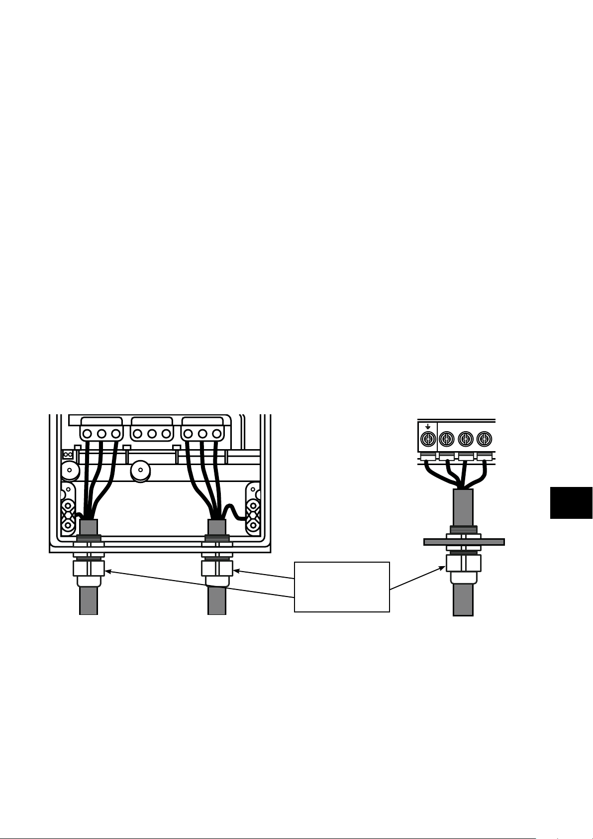
General
1
Compliance with category C1 conducted emissions only is achieved.
Supply Cable
2
A screened (shielded) cable suitable for fixed installation with the relevant mains voltage in use. Braided or twisted type screened
cable where the screen covers at least 85% of the cable surface area, designed with low impedance to HF signals. Installation of
a standard cable within a suitable steel or copper tube is also acceptable.
3
A cable suitable for fixed installation with relevant mains voltage with a concentric protection wire. Installation of a standard cable
within a suitable steel or copper tube is also acceptable – in this case, ensure that metal tube is adequately grounded..
4
A cable suitable for fixed installation with relevant mains voltage. A shielded type cable is not necessary.
Motor Cable
5
A screened (shielded) cable suitable for fixed installation with the relevant voltage in use. Braided or twisted type screened
cable where the screen covers at least 85% of the cable surface area, designed with low impedance to HF signals. Installation
of a standard cable within a suitable steel or copper tube is also acceptable - in this case, ensure that metal tube is adequately
grounded.
6
The cable shield should be terminated at the motor end using an EMC type gland allowing connection to the motor body through
the largest possible surface area. The shield must also be terminated at the drive end, as close as practically possible to the drive
output terminals. Where drives are mounted in a steel control panel enclosure, the cable screen may be terminated directly to the
control panel backplate using a suitable EMC clamp or gland fitted as close to the drive as possible. The drive earth terminal must
also be connected directly to this point, using a suitable cable which provides low impedance to high frequency currents. For IP55
and IP66 drives, connect the motor cable shield to the gland plate or internal ground clamp.
7
A cable suitable for fixed installation with relevant mains voltage with a concentric protection wire. Installation of a standard cable
within a suitable steel or copper tube is also acceptable.
Control Cable
8
A shielded cable with low impedance shield. Twisted pair cable is recommended for analog signals.
Electrical Installation
4.13.3. Enclosed Drives Recommended Cable Connections
IP55 IP66
L1 L2 L3
+DC BR -DC
U V W
U V W
For Best-Practice use 360°
bonding IP66 (or higher)
EMC cable gland shielded
to drive chassis.
4.14. Safe Torque Off
Safe Torque OFF will be referred to as “STO” through the remainder of this section.
4.14.1. Responsibilities
The overall system designer is responsible for defining the requirements of the overall “Safety Control System” within which the drive
will be incorporated; furthermore the system designer is responsible for ensuring that the complete system is risk assessed and that the
“Safety control System” requirements have been entirely met and that the function is fully verified, this must include confirmation testing
of the “STO” function before drive commissioning.
The system designer shall determine the possible risks and hazards within the system by carrying out a thorough risk and hazard
analysis, the outcome of the analysis should provide an estimate of the possible hazards, furthermore determine the risk levels and
identify any needs for risk reduction. The “STO” function should be evaluated to ensure it can sufficiently meet the risk level required.
4
Version 3.04 | Optidrive P2 User Guide | 29www.invertekdrives.com
Page 30
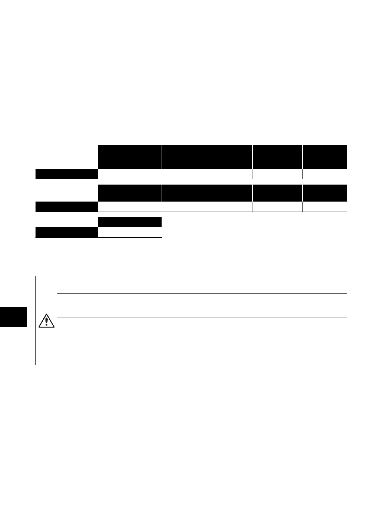
4.14.2. What STO Provides
The purpose of the “STO“ function is to provide a method of preventing the drive from creating torque in the motor in the absence
of the “STO“ input signals (Terminal 12 with respect to Terminal 13), this allows the drive to be incorporated into a complete safety
control system where “STO“ requirements need to be fulfilled.
1
The “STO“ function can typically eliminate the need for electro-mechanical contactors with cross-checking auxiliary contacts as per
normally required to provide safety functions.
2
The drive has the “STO“ function built-in as standard and complies with the definition of “Safe torque off“ as defined by IEC 61800-52:2007.
The “STO“ function also corresponds to an uncontrolled stop in accordance with category 0 (Emergency Off), of IEC 60204-1. This
means that the motor will coast to a stop when the “STO” function is activated, this method of stopping should be confirmed as being
acceptable to the system the motor is driving.
The “STO“ function is recognised as a fail-safe method even in the case where the “STO“ signal is absent and a single fault within the
drive has occurred, the drive has been proven in respect of this by meeting the following safety standards:
EN 61800-5-2 2 1.23E-09 1/h (0.12 % of SIL 2) 50 20 Yrs
Electrical Installation
EN ISO 13849-1 PL d 1 4525a 3
EN 62061 SILCL 2
NOTE The values achieved above maybe jeopardised if the drive is installed outside of the Environmental limits detailed in section
10.1. Environmental.
4.14.3. What STO Does Not Provide
Disconnect and ISOLATE the drive before attempting any work on it. The “STO“ function does not prevent high voltages
from being present at the drive power terminals.
1
NOTE The “STO“ function does not prevent the drive from an unexpected re-start. As soon as the “STO“inputs receive the
relevant signal it is possible (subject to parameter settings) to restart automatically, Based on this, the function should not be
used for carrying out short-term non-electrical machinery operations (such as cleaning or maintenance work).
4
2
NOTE In some applications additional measures may be required to fulfil the systems safety function needs: the “STO“
function does not provide motor braking. In the case where motor braking is required a time delay safety relay and/or a
mechanical brake arrangement or similar method should be adopted, consideration should be made over the required
safety function when braking as the drive braking circuit alone cannot be relied upon as a fail safe method.
When using permanent magnet motors and in the unlikely event of multiple output power devices failing then the motor
could effectively rotate the motor shaft by 180/p degrees (Where p denotes number of motor pole pairs).
SIL
(Safety Integrity
Level)
PL
(Performance Level)
SILCL
PFHD
(Probability of dangerous
Failures per Hour)
CCF (%)
(Common Cause Failure)
SFF
(Safe failure
fraction %)
Lifetime
assumed
MTTFd Category
4.14.4. “STO“ Operation
When the “STO” inputs are energised, the “STO” function is in a standby state, if the drive is then given a “Start signal/command” (as
per the start source method selected in P1-13) then the drive will start and operate normally.
When the “STO” inputs are de-energised then the STO Function is activated and stops the drive (Motor will coast), the drive is now in
“Safe Torque Off” mode.
To get the drive out of “Safe Torque Off” mode then any “Fault messages” need to be reset and the drive “STO” input needs to be
re-energised.
4.14.5. “STO” Status and Monitoring
There are a number of methods for monitoring the status of the “STO” input, these are detailed below:
Drive Display
In Normal drive operation (Mains AC power applied), when the drives “STO” input is de-energised (“STO” Function activated) the
drive will highlight this by displaying “InHibit”.
NOTE If the drive is in a tripped condition then the relevant trip will be displayed and not “InHibit”.
30 | Optidrive P2 User Guide | Version 3.04 www.invertekdrives.com
Page 31
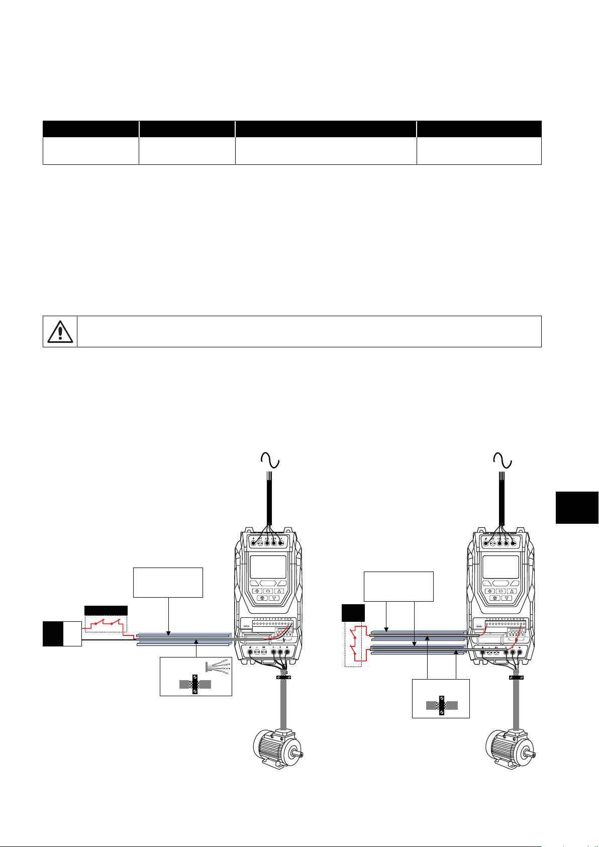
Drive Output Relay
1213
Protective Capped Trunking
or equivalent to prevent
STO Cable short circuit to an
external Voltage source.
1 7
Safety
relay
Protected
shielded cables
Drive relay 1: Setting P2-15 to a value of “13” will result in relay opening when the “STO” function is activated.
Drive relay 2: Setting P2-18 to a value of “13” will result in relay opening when the “STO” function is activated.
“STO” Fault Codes
Fault Code Code Number Description Corrective Action
“Sto-F” 29
A fault has been detected within either of the
internal channels of the “STO” circuit.
Refer to your Invertek Sales
Partner
4.14.6. “STO ” Function Response Time
The total response time is the time from a safety related event occurring to the components (sum of) within the system responding and
becoming safe. (Stop Category 0 in accordance with IEC 60204-1).
The response time from the “STO” inputs being de-energised to the output of the drive being in a state that will not produce torque
in the motor (“STO” active) is less than 1ms.
The response time from the “STO” inputs being de-energised to the “STO” monitoring status changing state is less than 20ms.
The response time from the drive sensing a fault in the STO circuit to the drive displaying the fault on the display/Digital output
showing drive not healthy is less than 20ms.
4.14.7. “STO“ Electrical Installation
The “STO” wiring shall be protected from inadvertent short circuits or tampering which could lead to failure of the “STO”
input signal, further guidance is given in the diagrams below.
In addition to the wiring guidelines for the “STO” circuit below, section 4.13.1. Recommended Installation for EMC Compliance on
page 28 should also be followed.
The drive should be wired as illustrated below; the 24V DC signal source applied to the “STO” input can be either from the 24V DC
on the drive or from an External 24V DC power supply.
4.14.8. Recommended “STO” Wiring
Using an External 24V DC Power Supply Using the Drives On-board 24V DC Supply
External
Power
Supply
+24Vdc
0V
Safety relay
Protective Capped Trunking
or equivalent to prevent
STO Cable short circuit to an
external Voltage source
.
1213
Protective Capped Trunking
or equivalent to prevent
STO Cable short circuit to an
external Voltage source.
Safety
relay
1 7
1213
Electrical Installation
4
- Twisted-Pair
- Shielded cables
Protected
shielded cables
Version 3.04 | Optidrive P2 User Guide | 31www.invertekdrives.com
Page 32

+24V DC
NOTE The Maximum cable length from Voltage source to the drive terminals should not exceed 25 mtrs.
4.14.9. External Power Supply Specification
Voltage Rating (Nominal) 24V DC
STO Logic High 18-30V DC (Safe torque off in standby)
Current Consumption (Maximum) 100mA
4.14.10. Safety Relay Specification
The safety relay should be chosen so that at minimum it meets the safety standards that the drive meets.
Electrical Installation
Standard Requirements SIL2 or PLd SC3 or better (With Forcibly guided Contacts)
Number of Output Contacts 2 independent
Switching Voltage Rating 30V DC
Switching Current 100mA
Wires should be
protected against
short circuits as shown
above
4
4.14.11. Enabling the “STO” Function
The “STO” function is always enabled in the drive regardless of operating mode or parameter changes made by the user.
4.14.12. Testing the “STO” Function
Before commissioning the system the “STO” function should always be tested for correct operation, this should include the following
tests:
With the motor at standstill, and a stop command given to the drive (as per the start source method selected in P1-13):
o De-energise the “STO” inputs (Drive will display ““InHibit”).
o Give a start command (as per the start source method selected in P1-13) and check that the drive still displays “Inhibit” and that
the operation is in line with the section 4.14.4. “STO“ Operation and section 4.14.5. “STO” Status and Monitoring.
With the motor running normally (from the drive):
o De-energise the “STO” inputs.
o Check that the drive displays “Inhibt” and that the motor stops and that the operation is in line with the section and section 4.14.4.
“STO“ Operation and section 4.14.5. “STO” Status and Monitoring.
4.14.13. “STO” Function Maintenance
The “STO” function should be included within the control systems scheduled maintenance program so that the function is regularly
tested for integrity (Minimum once per Year), furthermore the function should be integrity tested following any safety system
modifications or maintenance work. If drive fault messages are observed refer to section 11.1. Fault Messages on page 78 for
further guidance.
32 | Optidrive P2 User Guide | Version 3.04 www.invertekdrives.com
Page 33

5. Keypad and Display Operation
The drive is configured and its operation monitored via the keypad and display.
5.1. Keypad and Display Layout
Control Keypad provides access to the drive parameters, and also allows control of the drive when Keypad Mode is selected in P1-12.
IP20 & IP66 models keypad with TFT display
Main Displayed Parameter
Shows the drive status or the value of
whichever of the selectable parameters is
currently being shown on the main display.
Operating Information
Provides a real time display of key operating
information, e.g. output current and power.
Quick Help Button
Provides access to short
description of the displayed messages.
F1 Button
Functional Button which can be programmed
only in internal PLC function block.
Start Button
When in Hand mode, used to Start the drive.
Stop / Reset Button
Used to reset a tripped drive.
When in Keypad mode, used to Stop the
drive.
Main Displayed Parameter
Shows the drive status or the value of
whichever of the selectable parameters is
currently being shown on the main display.
Operating Information
Provides a real time display of key
operating information, e.g. output current
and power.
Start Button
When in Hand mode, used to Start the
drive.
Stop / Reset Button
Used to reset a tripped drive.
When in Keypad mode, used to Stop the
drive.
IP55 models keypad with OLED display
P2 01
STOP
37kW 400V 3Ph
F1
F2
P2 01
STOP
37kW 400V 3Ph
Drive Address
Drive serial communication address set
in parameter P5-01.
Navigate Button
Used to display real-time information,
to access and exit parameter edit mode
and to store parameter changes.
F2 Button
Functional Button which can be
programmed only in internal PLC
function block.
Up Button
Used to increase speed in real-time
mode or to increase parameter values
in parameter edit mode.
Down Button
Used to decrease speed in real-time
mode or to decrease parameter values
in parameter edit mode.
Drive Address
Drive serial communication address set
in parameter P5-01.
Navigate Button
Used to display real-time information,
to access and exit parameter edit mode
and to store parameter changes.
Up Button
Used to increase speed in real-time
mode or to increase parameter values
in parameter edit mode.
Down Button
Used to decrease speed in real-time
mode or to decrease parameter values
in parameter edit mode.
Keypad and Display Operation
5
Version 3.04 | Optidrive P2 User Guide | 33www.invertekdrives.com
Page 34

5.2. Selecting the Language on the TFT and OLED Display
P2 01 Select Language Select Language
STOP
15 kW 400V 3Ph
Español
Deutsch
English
Español
Deutsch
English
Hold down the Start
and Up keys for >1s.
Use the Up and Down
arrows to select a
language.
Press the Navigate
button to select.
5.2.1. Operating Displays
Keypad and Display Operation
Inhibit /
STO Active
TFT and OLED Display :
P2 01 P2 01
Drive Stopped Drive Running
Output Frequency
Output Frequency 01
INHIBIT STOP 23.7Hz 15.3A 6.9kW 718rpm
15 kW 400V 3Ph 15 k W 400V 3Ph 15.3A 6.9kW 6.9kW 23.7Hz 23.7Hz 15.3A 23.7Hz 15.3A
Drive Inhibited. The
STO connections are
not made.
Refer to section
4.14.8. Recommended
“STO” Wiring on
page 31.
Drive Stopped /
Disabled.
Drive is enabled
/ running, display
shows the output
frequency (Hz). Press
the Navigate key
to select alternative
displays.
Display
Drive Running
Output Current
Display
Motor Current 01 Motor Power 01 Motor Speed 01
Press the Navigate
key for < 1 second.
The display will show
the motor current
(Amps).
Drive Running
Motor Power
Display
Press the Navigate
key for < 1 second.
The display will show
the motor power
(kW).
Drive Running
Motor Speed
Display
If P1-10 > 0, pressing
the Navigate key for <
1 second will display
the motor speed
(RPM).
5
5.3. Additional Display Messages
Auto Tuning in
Progress
TFT and OLED Display :
Auto-tuning
Auto tune in progress.
See parameter P4-02
information in section
8.2.3. Parameter
Group 4 – High
Performance Motor
Control on page 53.
External 24V DC
Supply
P2 01 P2 01 P2 01 P2 01 P2 01
Ext 24V
External 24V mode
The drive control
board is powered
only from an external
24 Volt source, with
no mains power
applied.
OL
15.3A 6.9kW 15.3A 6.9kW 15.3A 6.9kW 15.3A 6.9kW
Indicates an
Overload condition.
Output current
exceeds the motor
rated current entered
in Parameter P1-08.
Overload Switching
23.7Hz
Frequency
Reduction
SF
23.7Hz
Switching frequency is
reduced, due to high
heatsink temperature.
Mains Loss Maintenance
ML
23.7Hz 23.7Hz
The incoming mains
power supply has
been disconnected or
is missing.
Time Elapsed
The user
programmable
maintenance reminder
time has elapsed.
34 | Optidrive P2 User Guide | Version 3.04 www.invertekdrives.com
Page 35

5.4. Changing Parameters
TFT and OLED Display :
P2 01 P2 01 P2 01 P2 01 P2 01
Stop
15 kW 400V 3Ph 50.0Hz 30.0A P1-08
Press and hold the
Navigate key > 2
seconds.
P1-01 P1-08
Use the up and down
keys to select the
required parameter.
Drives with OLED
display will show the
present parameter
value on the lower
line of the display.
Press the Navigate
key for < 1 second.
30.0A
Adjust the value using
the Up and Down
keys. Drives with
OLED display will
show the maximum
and minimum possible
settings on the lower
line of the display.
30.0 3.0
P1-08
30.0A 15k W 400V 3Ph
Press for < 1 second
to return to the
parameter menu.
Stop
Press for > 2 seconds
to return to the
operating display.
5.5. Parameter Factory Reset / User Reset
Optidrive P2 provides a feature to allow the user to define their own default parameter set. After commissioning all required
parameters, the user can save these as the default parameters by setting P6-29 = 1. If required, the User Default Parameters may be
cleared by setting P6-29 = 2.
If the user wishes to reload the User Default Parameters from the drive memory, the following procedure is used.
Factory Parameter Reset, TFT and OLED Display :
P2 01 P2 01 P2 01 P2 01 P2 01 P2 01
User Parameter Reset, TFT and OLED Display :
Keypad and Display Operation
Stop
15 kW 400V 3Ph 50.0Hz 15 kW
Press and hold the Up,
Down, Start and Stop
keys for >2s.
P-Def
The display shows
P-Def. Briefly press the
Stop key.
Stop
400V
3Ph P1-08
The display returns to
Stop. All parameters
are reset to Factory
defaults.
Stop
30.0 3.0
Press and hold the Up,
Down and Stop keys
for >2s.
U-Def
30.0A 15k W
The display shows
U-Def. Briefly press
the Stop key.
The display returns to
Stop. All parameters
are reset to Factory
defaults.
Stop
400V
3Ph
5.6. Resetting the Drive Following a Trip
Optidrive P2 has many protection features, designed to protect both the drive and motor from accidental damage. When any of these
protection features are activated, the drive will trip, and display a fault message. The fault messages are listed in section 11.1. Fault
Messages on page 78.
When a trip occurs, after the cause of the trip has been investigated and rectified, the user can reset the trip in one of the following ways:
Press the keypad Stop key.
Power off the drive completely, then power on again.
If P1-13 > 0, switch off digital input 1, then back on again.
If P1-12 = 4, reset via the fieldbus interface.
If P1-12 = 6, reset via CAN.
5
Version 3.04 | Optidrive P2 User Guide | 35www.invertekdrives.com
Page 36

5.7. Keypad Shortcuts
The following shortcuts can be used to speed up selecting and changing parameters when using the keypad.
5.7.1. Selecting the Parameter Groups
When extended or advanced parameter access is enabled (see section 8. Extended Parameters on page 47), additional
parameter groups are visible, and may be selected quickly by the following method.
TFT and OLED Display :
Maximum frequency/Speed limit
Preset frequency/Speed 1
P1-01 P2-01
50.0Hz 5.0Hz
Whilst in the parameter selection menu,
press the Navigate and Up or Navigate
Keypad and Display Operation
and Down keys simultaneously.
The next highest or lowest
accessible parameter group will be
selected.
5.7.2. Selecting the Lowest Parameter in a Group
TFT and OLED Display :
Motor rated current
Maximum frequency/Speed limit
P1-08 P1-01
9.5A 50.0Hz
5
Whilst in the parameter selection
menu, press the Up and Down keys
simultaneously.
5.7.4. Adjusting Individual Digits
When editing parameter values and making large changes, e.g. setting the motor rated speed from 0 to 1500RPM, it is possible to
directly select the parameter digits using the following method.
TFT and OLED Display :
Extended menu access
Extended menu access Extended menu access Extended menu access Extended menu access Extended menu access
0 _0 _0 100 100 100
P1-14
30 000 0
P1-14
The next lowest accessible
parameter in the selected
parameter group will be selected.
30 000 0
P1-14
30 000 0
5.7.3. Setting a Parameter to the Minimum Value
TFT and OLED Display :
Maximum frequency/Speed limit Maximum frequency/Speed limit
1500 rpm 0 rpm
P1-01
Whilst editing a parameter
value, press the Up and Down
keys simultaneously.
P1-14
7500 rpm
30 000 0
0 rpm
P1-14
P1-01
The parameter will be set to the
lowest possible value.
30 000 0
7500 rpm
P1-14
0 rpm
30 000 0
Whilst editing a
parameter value, press
the Stop and Navigate
keys simultaneously.
36 | Optidrive P2 User Guide | Version 3.04 www.invertekdrives.com
The cursor will step
one digit to the left.
Repeating the key
press will move
another digit to the
left.
The individual digit
value may be
adjusted using the up
and down keys.
Adjust the value using
the Up and Down
keys.
When the cursor reaches
the highest accessible
digit, pressing Stop and
Navigate will return the
cursor to the right most
digit.
Press the Navigate
key to return to the
parameter selection
menu.
Page 37

6. Parameters
6.1. Parameter Set Overview
The Optidrive P2 Parameter set consists of 10 groups as follows:
Group 0 – Read Only Monitoring Parameters
Group 1 – Basic Configuration Parameters
Group 2 – Extended Parameters
Group 3 – PID Control Parameters
Group 4 – High Performance Motor Control Parameters
Group 5 – Field Bus Parameters
Group 6 – Advanced Options
Group 7 – Advanced Motor Control
Group 8 – Application Parameters
Group 9 – Advanced I/O Selection
When the Optidrive is reset to factory defaults, or is in its factory supplied state, only Group 1 Parameters can be accessed. In order
to allow access to parameters from the higher level groups, the access code must be changed as follows.
P1-14 = P2-40 (Default setting = 101). With this setting, parameter groups 1 – 5 can be accessed, along with the first 50 parameters
in Group 0.
P1-14 = P6-30 (Default setting = 201). With this setting, all parameters are accessible.
6.2. Parameter Group 1 – Basic Parameters
The basic parameter group allows the user to:
Enter the motor nameplate information
o P1-07 = Motor Rated Voltage
o P1-08 = Motor Rated Current
o P1-09 = Motor Rated Frequency
o P1-10 = (Optionally) Motor Rated Speed
Define the operating speed limits
o P1-01 = Maximum Frequency or Speed
o P1-02 = Minimum Frequency or Speed
Define the acceleration and deceleration times used when starting and stopping the motor, or changing speed
o P1-03 = Acceleration Time
o P1-04 = Deceleration Time
Select where the drive should receive it’s command signals from, and determine what functions are associated with the drive control
terminal inputs
o P1-12 Selects the control source
o P1-13 Assigns the functions to the digital inputs
These parameters will often provide enough functions to allow the user to complete basic commissioning in simple applications. The
parameters are described in more detail below.
Parameters
6
Version 3.04 | Optidrive P2 User Guide | 37www.invertekdrives.com
Page 38

Par. Description Minimum Maximum Default Units
P1-01 Maximum Frequency / Speed Limit P1-02 500.0 50.0 (60.0) Hz / Rpm
P1-02 Minimum Frequency / Speed Limit 0.0 P1-01 0.0 Hz / Rpm
P1-03 Acceleration Ramp Time See Below 5.0 / 10.0 Seconds
P1-04 Deceleration Ramp Time See Below 5.0 / 10.0 Seconds
P1-05 Stop Mode 0 4 0 -
Parameters
P1-06 Energy Optimiser 0 1 0 -
P1-07 Motor Rated Voltage / kE Drive Rating Dependent Volts
6
P1-08 Motor Rated Current Drive Rating Dependent Amps
P1-09 Motor Rated Frequency 10 500 50 (60) Hz
Maximum output frequency or motor speed limit – Hz or rpm.
If P1-10 >0, the value entered / displayed is in Rpm.
Minimum speed limit – Hz or rpm.
If P1-10 >0, the value entered / displayed is in Rpm.
Acceleration ramp time from 0 to base speed (P1-09) in seconds.
FS2 & FS3 : 5.0 Seconds Default Setting, 0.01 Seconds Resolution, 600.0 Seconds Maximum.
FS4 – FS7 : 10.0 Seconds Default Setting, 0.1 Seconds Resolution, 6000 Seconds Maximum.
Deceleration ramp time from base speed (P1-09) to standstill in seconds. When set to zero, it will coast to stop the motor.
FS2 & FS3 : 5.0 Seconds Default Setting, 0.01 Seconds Resolution, 600.0 Seconds Maximum.
FS4 – FS7 : 10.0 Seconds Default Setting, 0.1 Seconds Resolution, 6000.0 Seconds Maximum.
0 Ramp
1 Coast When the enable signal is removed, the drive output is immediately disabled, and the motor
2 Ramp, brake chopper
enabled
3 Coast, brake chopper
enabled
4 AC Flux Braking As Option 0, but additionally, AC Flux braking is used to increase the available braking
0 Disabled
1 Enabled When enabled, the Energy Optimiser attempts to reduce the overall energy consumed by
This parameter should be set to the rated (nameplate) voltage of the motor.
This parameter should be set to the rated (nameplate) current of the motor.
This parameter should be set to the rated (nameplate) frequency of the motor.
When the enable signal is removed, the drive will ramp to stop, with the rate controlled by
P1-04 as described above. In this mode, the drive brake transistor (where fitted) is disabled.
will coast (freewheel) to stop. If the load can continue to rotate due to inertia, and the drive
may possibly be re-enabled whilst the motor is still rotating, the spin start function (P2-26)
should be enabled. In this mode, the drive brake transistor (where fitted) is disabled.
When the enable signal is removed, the drive will ramp to stop, with the rate controlled by
P1-04 as described above. The Optidrive Brake chopper is also enabled in this mode.
When the enable signal is removed, the drive output is immediately disabled, and the motor
will coast (freewheel) to stop. If the load can continue to rotate due to inertia, and the drive
may possibly be re-enabled whilst the motor is still rotating, the spin start function (P2-
26) should be enabled. The drive brake chopper is enabled in this mode, however it will
only activate when required during a change in the drive frequency setpoint, and will not
activate when stopping.
torque.
the drive and motor when operating at constant speeds and light loads. The output voltage
applied to the motor is reduced. The Energy Optimiser is intended for applications where
the drive may operate for some periods of time with constant speed and light motor load,
whether constant or variable torque.
38 | Optidrive P2 User Guide | Version 3.04 www.invertekdrives.com
Page 39

Par. Description Minimum Maximum Default Units
P1-10 Motor Rated Speed 0 30000 0 RPM
This parameter can optionally be set to the rated (nameplate) rpm of the motor. When set to the default value of zero, all speed
related parameters are displayed in Hz, and the slip compensation for the motor is disabled. Entering the value from the motor
nameplate enables the slip compensation function, and the Optidrive display will now show motor speed in estimated rpm. All
speed related parameters, such as Minimum and Maximum Speed, Preset Speeds etc. will also be displayed in Rpm.
NOTE When the drive is operated with the optional Encoder Feedback Interface, this parameter must be set to the correct
nameplate Rpm of the connected motor.
P1-11 Boost Voltage 0.0 Drive Rating Dependent %
Voltage boost is used to increase the applied motor voltage at low output frequencies, in order to improve low speed and starting
torque. Excessive voltage boost levels may result in increased motor current and temperature, and force ventilation of the motor may
be required.
An automatic setting () is also possible, whereby the Optidrive will automatically adjust this parameter based on the motor
parameters measured during an autotune.
P1-12 Primary Command Source 0 6 0 -
0 Terminal Control
1 Keypad control -
uni-directional
2 Keypad control -
bi-directional
3 PID Control
4 Fieldbus Mode
5 Slave Mode
6 CANopen Mode
P1-13 Digital Input Function 0 21 1 -
Defines the function of the digital inputs depending on the control mode setting in P1-12. See section 7.1. Control Source Selection for
more information.
P1-14 Extended Menu Access 0 30000 0 -
Parameter Access Control. The following settings are applicable:
P1-14 = P2-40 = 101 : Allows access to Extended Parameter Groups 0 – 5
P1-14 = P6-30 = 201 = Allows access to all parameter groups (Intended for experienced users only, usage is not described in this
User Guide).
The drive responds directly to signals applied to the control terminals.
The drive can be controlled in the forward direction only using an external or remote
Keypad.
The drive can be controlled in the forward and reverse directions using an external or
remote Keypad. Pressing the keypad START button toggles between forward and reverse.
The output frequency is controlled by the internal PID controller.
Control via Modbus RTU if no fieldbus interface option is present, otherwise control is from
the fieldbus option module interface.
The drive acts as a Slave to a connected Optidrive operating in Master Mode.
Control via CAN bus connected to the RJ45 serial interface connector.
Parameters
6
Version 3.04 | Optidrive P2 User Guide | 39www.invertekdrives.com
Page 40

7. Control Terminal Functions
For standard applications and operation, the basic control of the drive and functions of all drive input terminals can be configured
using just two parameters, P1-12 and P1-13. P1-12 is used to define the source of all control commands and the primary speed
reference source. P1-13 then allows fast selection of Analog and Digital Input functions based on a selection table.
7.1. Control Source Selection
7.1.1. P1-12 Function
P1-12 is used to select the main control source of the drive and the main speed reference according to the following table:
Control Terminal Functions
7
P1-12 Function Control Source
0 Terminal Control Terminals Analog Input 1 All control signals are applied to the control terminals. Functions are
Keypad Control
1
(Uni-directional)
Keypad Control
2
(Bi-directional)
3 PID Control Terminals PID Output
Fieldbus /
4
Modbus RTU
5 Slave Mode Master Drive From Master
6 CANopen CAN bus CAN bus
Keypad / Terminals
Keypad / Terminals
Modbus RTU
Main Speed
Reference
Motorised Pot /
Keypad
Motorised Pot /
Keypad
Fieldbus /
Modbus RTU
Notes
determined by P1-13 Macro setting.
When keypad mode is selected, the default operation of the drive
requires the keypad Start & Stop buttons are used to control the drive.
This can be changed using P2-37 to allow the drive to be started
from Digital Input 1 directly.
Enable / Disable control of the drive is through the drive control
terminal strip.
Output frequency is set by the output of the PI Controller.
Control of the drive operation is through a fieldbus option module
mounted in the drive option slot. If no option module is fitted, control is
through the Modbus RTU interface.
Digital Input 1 must be closed to allow operation.
Optidrive P2 provides an inbuilt Master / Slave function. A single
drive acts as the Master, and connected Slave drives will mimic the
starting and stopping, along with following the output frequency, with
any scaling applied.
Digital Input 1 must be closed to allow operation.
Control of the drive operation is through the CAN Open Interface.
Digital Input 1 must be closed to allow operation.
7.1.2. Overview
Optidrive P2 uses a Macro approach to simplify the configuration of the Analog and Digital Inputs. There are two key parameters
which determine the input functions and drive behaviour:
P1-12 – Selects the main drive control source and determines how the output frequency of the drive is primarily controlled.
P1-13 – Assigns the Macro function to the analog and digital inputs.
Additional parameters can then be used to further adapt the settings, e.g.
P2-30 – Used to select the format of the analog signal to be connected to analog input 1, e.g. 0 – 10 Volt, 4 – 20mA.
P2-33 – Used to select the format of the analog signal to be connected to analog input 2, e.g. 0 – 10 Volt, 4 – 20mA.
P2-36 – Determines whether the drive should automatically start following a power on if the Enable Input is present.
P2-37 – When Keypad Mode is selected, determines at what output frequency / speed the drive should start, following the
enable command, and also whether the keypad start key must be pressed or if the Enable input alone should start the drive.
The following diagrams and tables provide an overview of the functions of each terminal macro function, and a simplified connection
diagram for each.
40 | Optidrive P2 User Guide | Version 3.04 www.invertekdrives.com
Page 41

7.1.3. Macro Function Guide
Function Explanation
STOP
RUN
FWD
REV
RUN FWD
RUN REV
ENABLE
START
^- START -^
STOP
STARTFWD
STARTREV
^-FAST STOP (P2-25)-^
FAST STOP (P2-25)
E-TRIP
Analog Input AI1
Analog Input AI2
AI1 REF
AI2 REF
P2-0X REF
PR-REF
PI-REF
PI FB
KPD REF
INC SPD
DEC SPD
FB REF
(NO)
(NC)
DECEL P1-04
DECEL P8-11
Latched Input, Open the contact to STOP the drive.
Latched input, Close the contact to Start, the drive will operate as long as the input is maintained.
Latched Input, selects the direction of motor rotation FORWARD.
Latched Input, selects the direction of motor rotation REVERSE.
Latched Input, Close to Run in the FORWARD direction, Open to STOP.
Latched Input, Close to Run in the REVERSE direction, Open to STOP.
Hardware Enable Input.
In Keypad Mode, P2-37 determines whether the drive immediately starts, or the keypad start key must be pressed.
In other modes, this input must be present before the start command is applied via the fieldbus interface.
Normally Open, Rising Edge, Close momentarily to START the drive (NC STOP Input must be maintained).
Simultaneously applying both inputs momentarily will START the drive (NC STOP Input must be maintained).
Normally Closed, Falling Edge, Open momentarily to STOP the drive.
Normally Open, Rising Edge, Close momentarily to START the drive in the forward direction (NC STOP Input must
be maintained).
Normally Open, Rising Edge, Close momentarily to START the drive in the reverse direction (NC STOP Input must
be maintained).
When both inputs are momentarily active simultaneously, the drive stops using Fast Stop Ramp Time P2-25.
Normally Closed, Falling Edge, Open momentarily to FAST STOP the drive using Fast Stop Ramp Time P2-25.
Normally Closed, External Trip input. When the input opens momentarily, the drive trips showing - or
-h depending on P2-33 setting. See section 4.12.2. Motor Thermistor Connection on page 27 for
further information.
Analog Input 1, signal format selected using P2-30.
Analog Input 2, signal format selected using P2-33.
Analog Input 1 provides the speed reference.
Analog Input 2 provides the speed reference.
Speed reference from the selected preset speed.
Preset speeds P2-01 – P2-08 are used for the speed reference, selected according to other digital input status.
PI Control Speed Reference.
Analog Input used to provide a Feedback signal to the internal PI controller.
Keypad Speed Reference selected.
Normally Open, Close the input to Increase the motor speed.
Normally Open, Close input to Decrease motor speed.
Selected speed reference from Fieldbus (Modbus RTU / CAN Open / Master depending on P1-12 setting).
Input is Normally Open, Close momentarily to activate the function.
Input is Normally Closed, Open momentarily to activate the function.
During deceleration and stopping, Deceleration Ramp 1 (P1-04) is used.
During deceleration and stopping, Deceleration Ramp 2 (P8-11) is used (Requires Advanced Parameter Access,
see section 6.1. Parameter Set Overview on page 37.
Control Terminal Functions
7
Version 3.04 | Optidrive P2 User Guide | 41www.invertekdrives.com
Page 42

Control Terminal Functions
7
7.2. Digital Input Configuration Parameter P1-13
P1-13 DI1 DI2 DI3 AI1 / DI4 AI2 / DI5
State 0 1 0 1 0 1 0 1 0 1
0 User defined
1 STOP RUN
2 STOP RUN
3 STOP RUN
4 STOP RUN
5 STOP RUN
6 STOP RUN
7 STOP RUN
8 STOP RUN
9 STOP RUN
10 STOP RUN
11 STOP
12 STOP
13 STOP
14 STOP
15 STOP
RUN FWD
RUN FWD
RUN FWD
RUN FWD
RUN FWD
FWD REV
FWD REV
FWD REV
FWD REV
FWD REV
FWD REV
FWD REV
FWD REV
FWD REV
FWD REV
STOP
STOP
STOP
STOP
STOP
RUN REV
RUN REV
RUN REV
RUN REV
RUN REV
P1-12 REF P2-01 Analog Input AI1 P2-01 P2-02
DI3 DI4 DI5 Preset Speed
0 0 0 P2-01 REF
1 0 0 P2-02 REF
0 1 0 P2-03 REF
1 1 0 P2-04 REF
0 0 1 P2-05 REF
1 0 1 P2-06 REF
0 1 1 P2-07 REF
1 1 1 P2-08 REF
P1-12 REF P2-01 REF Analog Input AI1 Analog Input AI2
P1-12 REF P2-01 REF Analog Input AI1 DECEL P1-04 DECEL P8-11
P1-12 REF AI2 REF Analog Input AI1 Analog Input AI2
P1-12 REF P2-01 REF Analog Input AI1 E-TRIP OK
DI3 DI4 Preset Speed E-TRIP OK
Off Off P2-01 REF
On Off P2-02 REF
Off On P2-03 REF
On On P2-04 REF
DI3 DI4 Preset Speed DECEL P1-04 DECEL P8-11
Off Off P2-01 REF
On Off P2-02 REF
Off On P2-03 REF
On On P2-04 REF
DI3 DI4 Preset Speed P1-12 REF PR-REF
Off Off P2-01 REF
On Off P2-02 REF
Off On P2-03 REF
On On P2-04 REF
(NO)
P1-12 REF PR-REF Analog Input AI1 P2-01 REF P2-02 REF
P1-12 REF P2-01 REF Analog Input AI1 Analog Input AI2
P1-12 REF P2-01 REF Analog Input AI1 DECEL P1-04 DECEL P8-11
P1-12 REF AI2-REF Analog Input AI1 Analog Input AI2
INC SPD
DI3 DI4 DI5 Preset Speed
Off Off Off P2-01 REF
On Off Off P2-02 REF
Off On Off P2-03 REF
On On Off P2-04 REF
Off Off On P2-05 REF
On Off On P2-06 REF
Off On On P2-07 REF
On On On P2-08 REF
(NO)
DEC SPD
P1-12 REF
1
P2-01-REF
42 | Optidrive P2 User Guide | Version 3.04 www.invertekdrives.com
Page 43
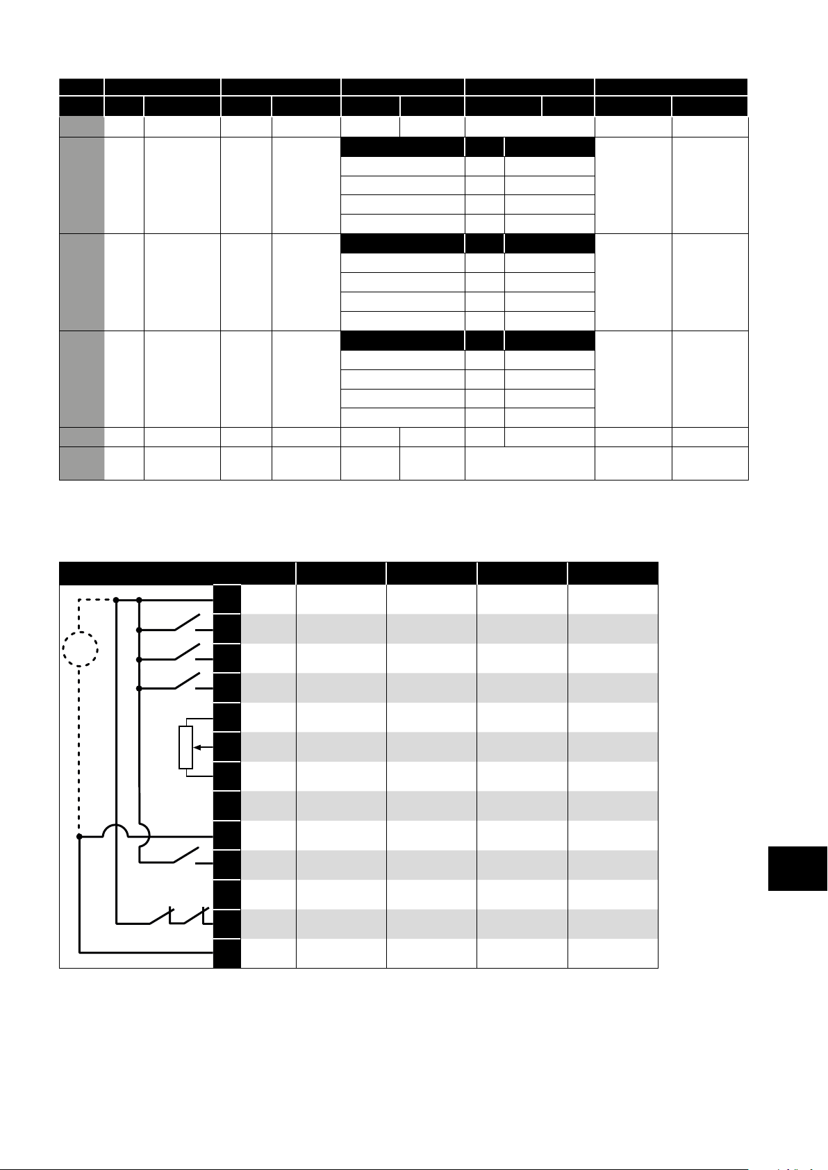
P1-13 DI1 DI2 DI3 AI1 / DI4 AI2 / DI5
State 0 1 0 1 0 1 0 1 0 1
16 STOP
17 STOP
18 STOP
19 STOP
20 STOP
21 (NO)
RUN FWD
RUN FWD
RUN FWD
RUN FWD
RUN FWD
START
FWD
STOP
STOP
STOP
STOP
STOP
STOP
RUN REV
RUN REV
RUN REV
RUN REV
RUN REV
(NC) (NO)
P1-12 REF P2-01 REF Analog Input AI1 E-TRIP OK
DI3 DI4 Preset Speed E-TRIP OK
Off Off P2-01 REF
On Off P2-02 REF
Off On P2-03 REF
On On P2-04 REF
DI3 DI4 Preset Speed DECEL P1-04 DECEL P8-11
Off Off P2-01 REF
On Off P2-02 REF
Off On P2-03 REF
On On P2-04 REF
DI3 DI4 Preset Speed P1-12 REF PR-REF
Off Off P2-01 REF
On Off P2-02 REF
Off On P2-03 REF
On On P2-04 REF
(NO)
INC SPD
START
REV
(NO)
DEC SPD
Analog Input AI1 P1-12 REF P2-01-REF
P1-12 REF
1
P2-01-REF
1) When P1-12 = 0 and P 1-13 = 10 or 20, the Motorised Pot / Keypad reference is automatically selected to be the Selected
Speed Reference.
7.3. Example Connection Schematics
P1-13 Setting: 1 4 11 14
+24V DC +24V DC +24V DC +24V DC +24V DC
1
+24 V DC*
+
_
DI 1 Disable / Enable Disable / Enable Run Forward Run Forward
2
DI 2
3
DI 3
4
+10V DC +10V DC +10V DC +10V DC +10V DC
5
AI 1 Analog Input 1 Analog Input 1 Analog Input 1 Analog Input 1
6
0V /
7
COM
AO 1
8
0V /
9
COM
DI 5
10
AO 2
11
STO+ STO+ STO+ STO+ STO+
12
Forward /
Reverse
P1-12 Reference /
PR Reference
0V / COM 0V / COM 0V / COM 0V / COM
Analog Output 1
(Motor Speed)
0V / COM 0V / COM 0V / COM 0V / COM
Preset Speed Select
(P2-01 / P2-02)
Analog Output 2
(Motor Current)
Forward /
Reverse
P1-12 Reference /
PR Reference
Analog Output 1
(Motor Speed)
Dec. Ramp Select
(P1-04 / P8-11)
Analog Output 2
(Motor Current)
Run Reverse Run Reverse
P1-12 Reference /
PR Reference
Analog Output 1
(Motor Speed)
Preset Speed Select
(P2-01 / P2-02)
Analog Output 2
(Motor Current)
P1-12 Reference /
PR Reference
Analog Output 1
(Motor Speed)
Dec. Ramp Select
(P1-04 / P8-11)
Analog Output 2
(Motor Current)
Control Terminal Functions
7
STO- STO- STO- STO- STO-
13
NOTE * Optional external 24V DC power supply
Version 3.04 | Optidrive P2 User Guide | 43www.invertekdrives.com
Page 44

+
_
P1-13 Setting: 2 8 9 12 18 19
+24 V DC*
+24V
1
DC
DI 1
2
DI 2
3
DI 3
4
+10V
5
DC
DI 4
6
0V /
7
COM
AO 1
8
0V /
9
COM
DI 5
10
AO 2
11
STO+ STO+ STO+ STO+ STO+ STO+ STO+
12
STO- STO- STO- STO- STO- STO- STO-
13
+24V DC +24V DC +24V DC +24V DC +24V DC +24V DC
Disable /
Enable
Forward /
Reverse
Preset Speed Select
BIT 0
+10V DC +10V DC +10V DC +10V DC +10V DC +10V DC
Preset Speed Select
BIT 1
0V / COM 0V / COM 0V / COM 0V / COM 0V / COM 0V / COM
Analog Output 1
(Motor Speed)
0V / COM 0V / COM 0V / COM 0V / COM 0V / COM 0V / COM
Preset Speed Select
BIT 2
Analog Output 2
(Motor Current)
Disable /
Enable
Forward /
Reverse
Preset Speed Select
BIT 0
Preset Speed Select
BIT 1
Analog Output 1
(Motor Speed)
Dec. Ramp Select
(P1-04 / P8-11)
Analog Output 2
(Motor Current)
Disable /
Enable
Forward /
Reverse
Preset Speed Select
BIT 0
Preset Speed Select
BIT 1
Analog Output 1
(Motor Speed)
P1-12 Reference
/
Preset Ref
Analog Output 2
(Motor Current)
Run Forward Run Forward Run Forward
Run Reverse Run Reverse Run Reverse
Preset Speed Select
BIT 0
Preset Speed Select
BIT 1
Analog Output 1
(Motor Speed)
Dec. Ramp Select
(P1-04 / P8-11)
Analog Output 2
(Motor Current)
Preset Speed Select
BIT 0
Preset Speed Select
BIT 1
Analog Output 1
(Motor Speed)
Dec. Ramp Select
(P1-04 / P8-11)
Analog Output 2
(Motor Current)
Preset Speed Select
BIT 0
Preset Speed Select
BIT 1
Analog Output 1
(Motor Speed)
P1-12 Reference
/
Preset Ref
Analog Output 2
(Motor Current)
Control Terminal Functions
7
P1-13 Setting: 3 5 13 15
+24V DC +24V DC +24V DC +24V DC +24V DC
1
+24 V DC*
+
_
DI 1 Disable / Enable Disable / Enable Run Forward Run Forward
2
DI 2
3
DI 3
4
+10V DC +10V DC +10V DC +10V DC +10V DC
5
AI 1 /
6
DI 4
0V /
7
COM
AO 1
8
0V /
9
COM
AI 2 /
10
DI 5
AO 2
11
STO+ STO+ STO+ STO+ STO+
12
STO- STO- STO- STO- STO-
13
Forward /
Reverse
P1-12 Reference /
P2-01 Reference
Analog Input 1 Analog Input 1 Analog Input 1 Analog Input 1
0V / COM 0V / COM 0V / COM 0V / COM
Analog Output 1
(Motor Speed)
0V / COM 0V / COM 0V / COM 0V / COM
Analog Input 2 Analog Input 2 Analog Input 2 Analog Input 2
Analog Output 2
(Motor Current)
Forward /
Reverse
P1-12 Reference /
AI 2 Reference
Analog Output 1
(Motor Speed)
Analog Output 2
(Motor Current)
Run Reverse Run Reverse
P1-12 Reference /
P2-01 Reference
Analog Output 1
(Motor Speed)
Analog Output 2
(Motor Current)
P1-12 Reference /
AI 2 Reference
Analog Output 1
(Motor Speed)
Analog Output 2
(Motor Current)
NOTE * Optional external 24V DC power supply
44 | Optidrive P2 User Guide | Version 3.04 www.invertekdrives.com
Page 45
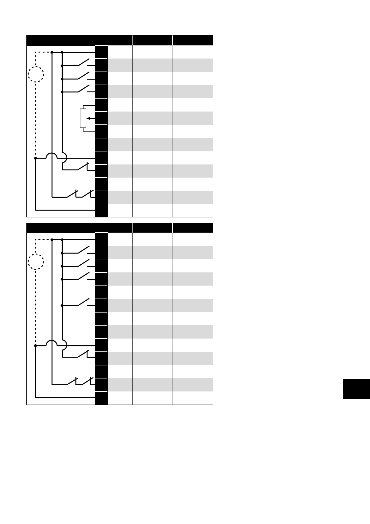
P1-13 Setting: 6 16
+24V DC +24V DC +24V DC
1
+
_
+
_
+24 V DC*
DI 1 Disable / Enable Run Forward
2
DI 2
3
DI 3
4
+10V DC +10V DC +10V DC
5
AI 1 Analog Input 1 Analog Input 1
6
0V /
7
COM
AO 1
8
0V /
9
COM
DI 5
10
AO 2
11
STO+ STO+ STO+
12
STO- STO- STO-
13
Forward /
Reverse
P1-12 Reference /
P2-01 Reference
0V / COM 0V / COM
Analog Output 1
(Motor Speed)
0V / COM 0V / COM
E-trip E-trip
Analog Output 2
(Motor Current)
P1-13 Setting: 7 17
+24V DC +24V DC +24V DC
1
+24 V DC*
DI 1 Disable / Enable Run Forward
2
DI 2
3
DI 3
4
+10V DC +10V DC +10V DC
5
DI 1
6
0V /
7
COM
AO 1
8
0V /
9
COM
DI 5
10
AO 2
11
STO+ STO+ STO+
12
STO- STO- STO-
13
Forward /
Reverse
Preset Speed Select
BIT 0
Preset Speed Select
BIT 1
0V / COM 0V / COM
Analog Output 1
(Motor Speed)
0V / COM 0V / COM
External trip (NC) External trip (NC)
Analog Output 2
(Motor Current)
Run Reverse
P1-12 Reference /
P2-01 Reference
Analog Output 1
(Motor Speed)
Analog Output 2
(Motor Current)
Control Terminal Functions
Run Reverse
Preset Speed Select
BIT 0
Preset Speed Select
BIT 1
Analog Output 1
(Motor Speed)
Analog Output 2
(Motor Current)
7
NOTE * Optional external 24V DC power supply
Version 3.04 | Optidrive P2 User Guide | 45www.invertekdrives.com
Page 46
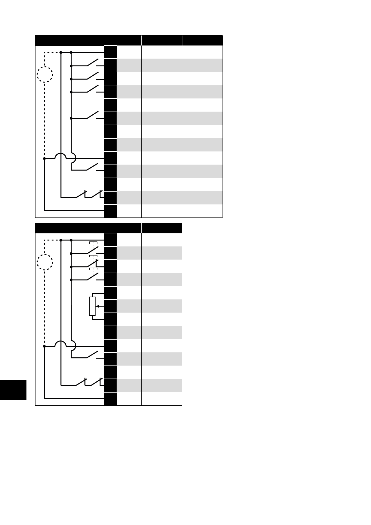
P1-13 Setting: 10 20
+24V DC +24V DC +24V DC
1
Control Terminal Functions
+
_
+
_
+24 V DC*
DI 1 Disable / Enable Run Forward
2
DI 2
3
DI 3
4
+10V DC +10V DC +10V DC
5
DI 4
6
0V /
7
COM
AO 1
8
0V /
9
COM
DI 5
10
AO 2
11
STO+ STO+ STO+
12
STO- STO- STO-
13
P1-13 Setting: 21
+24V DC +24V DC
1
+24 V DC*
DI 1
2
DI 2 NC Push Stop
3
DI 3
4
+10V DC +10V DC
5
Forward /
Reverse
Increase Speed Increase Speed
Decrease Speed Decrease Speed
0V / COM 0V / COM
Analog Output 1
(Motor Speed)
0V / COM 0V / COM
P1-12 Reference /
P2-01 Reference
Analog Output 2
(Motor Current)
NO Push Start
Forward
NO Push Start
Reverse
Run Reverse
Analog Output 1
(Motor Speed)
P1-12 Reference /
P2-01 Reference
Analog Output 2
(Motor Current)
7
AI 1 Analog Input 1
6
0V /
7
COM
AO 1
8
0V /
9
COM
DI 5
10
AO 2
11
STO+ STO+
12
STO- STO-
13
Analog Output 1
(Motor Speed)
P1-12 Reference /
P2-01 Reference
Analog Output 2
(Motor Current)
NOTE * Optional external 24V DC power supply
0V / COM
0V / COM
46 | Optidrive P2 User Guide | Version 3.04 www.invertekdrives.com
Page 47

8. Extended Parameters
8.1. Parameter Group 2 - Extended Parameters
Par Parameter Name Minimum Maximum Default Units
P2-01 Preset Jog Frequency / Speed 1 P1-02 P1-01 5.0 Hz / Rpm
P2-02 Preset Jog Frequency / Speed 2 P1-02 P1-01 10.0 Hz / Rpm
P2-03 Preset Jog Frequency / Speed 3 P1-02 P1-01 25.0 Hz / Rpm
P2-04 Preset Jog Frequency / Speed 4 P1-02 P1-01 50.0 (60.0) Hz / Rpm
P2-05 Preset Jog Frequency / Speed 5 P1-02 P1-01 0.0 Hz / Rpm
P2-06 Preset Jog Frequency / Speed 6 P1-02 P1-01 0.0 Hz / Rpm
P2-07 Preset Jog Frequency / Speed 7 P1-02 P1-01 0.0 Hz / Rpm
P2-08 Preset Jog Frequency / Speed 8 P1-02 P1-01 0.0 Hz / Rpm
Preset Speeds / Frequencies selected by digital inputs depending on the setting of P1-13.
If P1-10 = 0, the values are entered as Hz. If P1-10 > 0, the values are entered as Rpm.
Setting a negative value will reverse the direction of motor rotation.
P2-09 Skip Frequency Center Point P1-02 P1-01 0.0 Hz / Rpm
P2-10 Skip Frequency Band Width 0.0 P1-01 0.0 Hz / Rpm
The Skip Frequency function is used to avoid the Optidrive operating at a certain output frequency, for example at a frequency which
causes mechanical resonance in a particular machine. Parameter P2-09 defines the centre point of the skip frequency band, and is
used conjunction with P2-10. The Optidrive output frequency will ramp through the defined band at the rates set in P1-03 and P1-04
respectively, and will not hold any output frequency within the defined band. If the frequency reference applied to the drive is within
the band, the Optidrive output frequency will remain at the upper or lower limit of the band.
P2-11 Analog Output 1 Function (Terminal 8) 0 12 8 -
Digital Output Mode. Logic 1 = +24V DC
0 Drive running Logic 1 when the Optidrive is enabled (Running).
1 Drive healthy Logic 1 When no Fault condition exists on the drive.
2 At speed Logic 1 when the output frequency matches the setpoint frequency.
3 Motor speed > 0 Logic 1 when the motor runs above zero speed.
Motor speed >= limit
4
5 Motor current >=limit Logic 1 when the motor current exceeds the adjustable limit.
6 Motor torque >= Limit Logic when the motor torque exceeds the adjustable limit.
7 Analog input 2 >=limit Logic when the signal applied to the Analog Input 2 exceeds the adjustable limit.
NOTE When using settings 4 – 7, parameters P2-16 and P2-17 must be used together to control the behaviour. The output will switch
to Logic 1 when the selected signal exceeds the value programmed in P2-16, and return to Logic 0 when the signal falls below the
value programmed in P2-17.
Analog Output Mode
8 Motor speed 0 to P1-01.
9 Motor current 0 to 200% of P1-08.
Motor torque
10
11 Motor power 0 to 150% of drive rated power.
12 PID Output Output from the internal PID Controller, 0 – 100%.
P2-12 Analog Output 1 Format See Below
-
-
-
-
-
-
0 to10V
10 to 0V
0 to 20mA
20 to 0mA
4 to 20mA
20 to 4mA
Logic 1 when the motor speed exceeds the adjustable limit.
0 to 200% of motor rated torque.
-
Extended Parameters
-
8
Version 3.04 | Optidrive P2 User Guide | 47www.invertekdrives.com
Page 48

Par Parameter Name Minimum Maximum Default Units
P2-13
P2-14
Extended Parameters
P2-15
8
P2-16 Relay 1 / Analog Output 1 Upper Limit P2-17 200.0 100.0 %
Analog Output 2 Function (Terminal 11) 0 12 9 -
Digital Output Mode. Logic 1 = +24V DC
0 Drive running Logic 1 when the Optidrive is enabled (Running).
1 Drive healthy Logic 1 When no Fault condition exists on the drive.
2 At speed Logic 1 when the output frequency matches the setpoint frequency.
3 Motor speed > 0 Logic 1 when the motor runs above zero speed.
4
Motor speed >= limit
5 Motor current >= limit Logic 1 when the motor current exceeds the adjustable limit.
6 Motor torque >= limit Logic when the motor torque exceeds the adjustable limit.
7 Analog input 2 >= limit Logic when the signal applied to the Analog Input 2 exceeds the adjustable limit.
NOTE When using settings 4 – 7, parameters P2-19 and P2-20 must be used together to control the behaviour. The output will switch
to Logic 1 when the selected signal exceeds the value programmed in P2-19, and return to Logic 0 when the signal falls below the
value programmed in P2-20.
Analog Output Mode
8 Motor speed 0 to P1-01.
9 Motor current 0 to 200% of P1-08.
10
Motor torque
11 Motor power 0 to 150% of drive rated power.
12 PID output Output from the internal PID Controller, 0 – 100%.
Analog Output 2 Format See Below
-
-
-
-
-
-
Relay 1 Function 0 14 1 -
Setting Function Logic 1 when
NOTE When using settings 4 – 7 and 14, parameters P2-16 and P2-17 must be used together to control the behaviour. The output
will switch to Logic 1 when the selected signal exceeds the value programmed in P2-16, and return to Logic 0 when the signal falls
below the value programmed in P2-17.
0 to10V
10 to 0V
0 to 20mA
20 to 0mA
4 to 20mA
20 to 4mA
0 Drive running The Optidrive is enabled (Running).
1 Drive healthy No fault or trip condition exists on the drive.
2 At speed Output frequency matches the setpoint frequency.
3 Motor speed > 0 The motor runs above zero speed.
4
Motor speed >= limit
5 Motor current >= limit The motor current exceeds the adjustable limit.
6 Motor torque >= limit The motor torque exceeds the adjustable limit.
7 Analog input 2 >= limit The signal applied to the Analog Input 2 exceeds the adjustable limit.
8 Reserved No Function.
9 Reserved No Function.
10 Maintenance due The internally programmable maintenance timer has elapsed.
11 Drive ready to run 0 to 150% of drive rated power.
12 Drive tripped The drive is not tripped, the STO circuit is closed, the mains supply is present and the
13 STO status When both STO inputs are present and the drive is able to be operated.
14 PID error >= limit The PID Error (difference between setpoint and feedback) is greater than or equal to the
Logic 1 when the motor speed exceeds the adjustable limit.
0 to 200% of motor rated torque.
-
The motor speed exceeds the adjustable limit.
hardware enable input present (Digital Input 1 unless changed by the user).
programmed limit.
-
48 | Optidrive P2 User Guide | Version 3.04 www.invertekdrives.com
Page 49

Par Parameter Name Minimum Maximum Default Units
P2-17 Relay 1 / Analog Output 1 Lower Limit 0.0 P2-16 0.0 %
Used in conjunction with some settings of Parameters P2-11 & P2-15.
P2-18 Relay 2 Function 0 14 0 -
Setting Function Logic 1 when
0 Drive running The Optidrive is enabled (Running).
1 Drive healthy No fault or trip condition exists on the drive.
2 At speed Output frequency matches the setpoint frequency.
3 Motor speed > 0 The motor runs above zero speed.
Motor speed >= limit
4
5 Motor current >= limit The motor current exceeds the adjustable limit.
6 Motor torque >= limit The motor torque exceeds the adjustable limit.
7 Analog input 2 >= limit The signal applied to the Analog Input 2 exceeds the adjustable limit.
8 Hoist brake control Enables Hoist Mode. The Output relay may be used to control the motor holding brake.
9 Reserved No Function.
10 Maintenance due The internally programmable maintenance timer has elapsed.
11 Drive ready to run 0 to 150% of drive rated power.
12 Drive tripped The drive is not tripped, the STO circuit is closed, the mains supply is present and the
13 STO status When both STO inputs are present and the drive is able to be operated.
14 PID error >= limit The PID Error (difference between setpoint and feedback) is greater than or equal to the
NOTE When using settings 4 – 7 and 14, parameters P2-16 and P2-17 must be used together to control the behaviour. The output
will switch to Logic 1 when the selected signal exceeds the value programmed in P2-16, and return to Logic 0 when the signal falls
below the value programmed in P2-17.
P2-19 Relay 2 / Analog Output 2 Upper Limit P2-20 200.0 100.0 %
P2-20 Relay 2 / Analog Output 2 Lower Limit 0.0 P2-19 0.0 %
Used in conjunction with some settings of Parameters P2-13 & P2-18.
P2-21 Display Scaling Factor -30.000 30.000 0.000 -
P2-22 Display Scaling Source 0 3 0 -
P2-21 & P2-22 allow the user to program the Optidrive to display an alternative output unit scaled from an existing parameter, e.g. to
display conveyer speed in metres per second based on the output frequency. This function is disabled if P2-21 is set to 0.
If P2-21 is set >0, the variable selected in P2-22 is multiplied by the factor entered in P2-21, and displayed whilst the drive is running,
with a ‘c’ to indicate the customer scaled units.
P2-22 Options Scaled Value is
0 Motor Speed If P1-10 = 0, Output Frequency (Hz) x Scaling Factor
1 Motor Current Motor Amps x Scaling Factor
2 Analog Input 2 Analog Input 2 % (P0-02) x Scaling Factor
3 P0-80 Value P0-80 Value x Scaling Factor
P2-23 Zero Speed Holding Time 0.0 60.0 0.2 Seconds
Determines the time for which the drive output frequency is held at zero when stopping, before the drive output is disabled.
P2-24 Effective Switching Frequency Drive Rating Dependent kHz
Effective power stage switching frequency. The range of settings available and factory default parameter setting depend on the drive
power and voltage rating. Higher frequencies reduce the audible ‘ringing’ noise from the motor, and improve the output current waveform,
at the expense of increased drive losses.
P2-25 Fast Decel Ramp Time 0.00 240.0 0.00 Seconds
This parameter allows an alternative deceleration ramp down time to be programmed into the Optidrive, which can be selected by
digital inputs (dependent on the setting of P1-13) or selected automatically in the case of a mains power loss if P2-38 = 2.
When set to 0.0, the drive will coast to stop.
The motor speed exceeds the adjustable limit.
Refer to your Invertek Drives Sales Partner for further information.
hardware enable input present (Digital Input 1 unless changed by the user).
programmed limit.
If P1-10 > 0, Motor RPM x Scaling Factor
Extended Parameters
8
Version 3.04 | Optidrive P2 User Guide | 49www.invertekdrives.com
Page 50

Par Parameter Name Minimum Maximum Default Units
P2-26 Spin Start Enable 0 2 0 -
P2-27 Standby Mode Timer 0.0 250.0 0.0 Seconds
P2-28 Slave Speed Scaling Control 0 3 0 -
P2-29 Slave Speed Scaling Factor -500.0 500.0 100.0 %
P2-30 Analog Input 1 (Terminal 6) Format See Below
Extended Parameters
P2-31 Analog Input 1 Scaling 0.0 2000.0 100.0 %
P2-32 Analog Input 1 Offset -500.0 500.0 0.0 %
P2-33 Analog Input 2 (Terminal 10) Format See Below
8
0 Disabled Spin Start is not active. This setting should be used for all applications where the motor is
1 Enabled When enabled, on start up the drive will attempt to determine if the motor is already
2 Enabled on trip, brown
out, coast
This parameter defines the time period, whereby if the drive operates at the frequency / speed set in P3-14 (Standby speed threshold)
for greater than the set time period, the Optidrive output will be disabled, and the display will show . The function is disabled if
P2-27 = 0.0.
Active in Keypad mode (P1-12 = 1 or 2) and Slave mode (P1-12=5) only. The keypad reference can be multiplied by a preset scaling
factor or adjusted using an analog trim or offset.
0 Disabled (No Scaling)
1 Master Speed * P2-29
2 (Master Speed * P2-29) + analog input 1
3 (Master Speed * P2-29) * analog input 1
Used in conjunction with P2-28.
Setting Signal Format
-
-
--
-
-
-
-
-
Scales the analog input by this factor, e.g. if P2-30 is set for 0 – 10V, and the scaling factor is set to 200.0%, a 5 volt input will result in
the drive running at maximum speed (P1-01).
Sets an offset, as a percentage of the full scale range of the input, which is applied to the analog input signal.
Setting Signal Format
-
-
P-h
-
-
-
-
-
0 to 10 Volt Signal (Uni-polar)
10 to 0 Volt Signal (Uni-polar)
-10 to +10 Volt Signal (Bi-polar)
0 to 20mA Signal
4 to 20mA Signal, the Optidrive will trip and show the fault code - if the signal level falls below 3mA
4 to 20mA Signal, the Optidrive will ramp to Preset Speed 8 (P2-08) if the signal level falls below 3mA
20 to 4mA Signal, the Optidrive will trip and show the fault code - if the signal level falls below 3mA
20 to 4mA Signal, the Optidrive will ramp to Preset Speed 8 (P2-08) if the signal level falls below 3mA
0 to 10 Volt Signal (Uni-polar)
10 to 0 Volt Signal (Uni-polar)
Motor PTC Thermistor Input
0 to 20mA Signal
4 to 20mA Signal, the Optidrive will trip and show the fault code - if the signal level falls below 3mA
4 to 20mA Signal, the Optidrive will ramp to Preset Speed 8 (P2-08) if the signal level falls below 3mA
20 to 4mA Signal, the Optidrive will trip and show the fault code - if the signal level falls below 3mA
20 to 4mA Signal, the Optidrive will ramp to Preset Speed 8 (P2-08) if the signal level falls below 3mA
always stationary before the drive is enabled.
rotating, and will begin to control the motor from its current speed. A short delay may be
observed when starting motors which are not turning.
Spin start is active only following the listed conditions, otherwise spin start is disabled.
-
-
-
-
50 | Optidrive P2 User Guide | Version 3.04 www.invertekdrives.com
Page 51

Par Parameter Name Minimum Maximum Default Units
P2-34 Analog Input 2 Scaling 0.0 2000.0 100.0 %
Scales the analog input by this factor, e.g. if P2-30 is set for 0 – 10V, and the scaling factor is set to 200.0%, a 5 volt input will result in
the drive running at maximum speed (P1-01).
P2-35 Analog Input 2 Offset -500.0 500.0 0.0 %
Sets an offset, as a percentage of the full scale range of the input, which is applied to the analog input signal.
P2-36 Start Mode Select / Automatic Restart See Below
Defines the behaviour of the drive relating to the enable digital input and also configures the Automatic Restart function.
e-
-
-
-
-
-
-
DANGER! “ modes allow the drive to Auto-start, therefore the impact on system/Personnel
P2-37 Keypad Start Mode 0 7 1 -
This parameter is only active when P1-12 = 1 or 2. When settings 0 to 3 are used, the drive must be started by pressing the Start key
on the keypad. When settings 4 – 7 are used, the drive starting is controlled by the enable digital input.
P2-38 Mains Loss Stop / Ride Through 0 3 0 -
P2-39 Parameter Lock 0 1 0 -
P2-40 Extended Menu Access Code 0 9999 101 -
Defines the access code which must be entered in P1-14 to access parameter groups above Group 1.
Following Power on or reset, the drive will not start if Digital Input 1 remains closed. The Input must be closed after a power
on or reset to start the drive.
Following a Power On or Reset, the drive will automatically start if Digital Input 1 is closed.
Following a trip, the drive will make up to 5 attempts to restart at 20 second intervals. The drive must be powered down to
reset the counter. The numbers of restart attempts are counted, and if the drive fails to start on the final attempt, the drive will
fault with, and will require the user to manually reset the fault.
safety needs to be considered.
0 Minimum speed,
keypad start
1 Previous speed,
keypad start
2 Current speed,
keypad start
3 Preset speed 8,
keypad start
4
Minimum speed,
terminal start
Previous speed,
5
terminal start
6 Current speed,
terminal start
7 Preset speed 8,
terminal start
0 Mains Loss Ride Through The Optidrive will attempt to continue operating by recovering energy from the load
1 Coast To Stop The Optidrive will immediately disable the output to the motor, allowing the load to coast
2 Fast Ramp To Stop The drive will ramp to stop at the rate programmed in the 2nd deceleration time P2-25.
3 DC bus supply mode
0 Unlocked All parameters can be accessed and changed.
1 Locked Parameter values can be displayed, but cannot be changed.
Following a stop and restart, the drive will always initially run at the minimum speed P1-02.
Following a stop and restart, the drive will return to the last keypad setpoint speed used
prior to stopping.
Where the Optidrive is configured for multiple speed references (typically Hand / Auto
control or Local / Remote control), when switched to keypad mode by a digital input, the
drive will continue to operate at the last operating speed.
Following a stop and restart, the Optidrive will always initially run at Preset Speed 8 (P2-08).
motor. Providing that the mains loss period is short, and sufficient energy can be recovered
before the drive control electronics power off, the drive will automatically restart on return
of mains power.
or free wheel. When using this setting with high inertia loads, the Spin Start function (P2-
26) may need to be enabled.
This mode is intended to be used when the drive is powered directly via the +DC and –DC
Bus connections. Refer to your Invertek Sales Partner for further details.
-
%
Extended Parameters
8
Version 3.04 | Optidrive P2 User Guide | 51www.invertekdrives.com
Page 52

8.2. Parameter Group 3 – PID Control
8.2.1. Overview
Optidrive P2 provides an internal PID controller. Parameters for configuration of the PID controller are located together in Group 3.
For simple applications, the user needs to only define the setpoint source (P3-05 to select the source or P3-06 for a fixed setpoint),
feedback source (P3-10) and adjust the P Gain (P3-01), I time (P3-02) and optionally the differential time (P3-03).
The PID operation is uni-directional, and all signals are treated as 0 – 100% to provide a simple, intuitive operating format.
8.2.2. Parameter List
Par Parameter Name Minimum Maximum Default Units
P3-01 PID Proportional Gain 0.0 30.0 1. 0 -
P3-02 PID Integral Time Constant 0.0 30.0 1.0 s
P3-03 PID Differential Time Constant 0.00 1.00 0.00 s
P3-04 PID Operating Mode 0 1 0 -
P3-05 PID Reference Select 0 2 0 -
P3-06 PID Digital Reference Value 0.0 100.0 0.0 %
P3-07 PID Output Upper Limit P3-08 100.0 100.0 %
Extended Parameters
P3-08 PID Output Lower Limit 0.0 P3-07 0.0 %
P3-09 PID Output Limit Select 0 3 0 -
P3-10 PID Feedback Select 0 5 0 -
8
P3-11 PID Error To Enable Ramp 0.0 25.0 0.0 %
PID Controller Proportional Gain. Higher values provide a greater change in the drive output frequency in response to small changes
in the feedback signal. Too high a value can cause instability.
PID Controller Integral Time. Larger values provide a more damped response for systems where the overall process responds slowly.
PID Differential Time Constant.
0 Direct Use this mode if an increase in the motor speed should result in an increase in the
1 Inverse Use this mode if an increase in the motor speed should result in a decrease in the
0 Digital preset P3-06 is used.
1 Analog Input 1 Analog Input 1 as displayed in P0-01 is used.
2 Analog Input 2 Analog Input 2 as displayed in P0-02 is used.
When P3-05 = 0, this parameter sets the preset digital reference (setpoint) used for the PID Controller. Where the feedback is provided
from a transducer such as a pressure transducer or level measurement, this represents the percentage of the pressure range (e.g. for a 0 –
10 Bar transducer, 4 bar = 40%) or the level.
Limits the maximum value output from the PID controller.
Limits the minimum output from the PID controller.
0 Digital Output Limits The output range of the PID controller is limited by the values of P3-07 & P3-08.
1 Upper limit set by analog
input 1
2 Lower limit set by analog
input 1
3 PID output added to analog
input 1
0 Analog Input 2
1 Analog Input 1
2 Motor Current
3 DC Bus Voltage
4 Differential : Analog Input 1 – Analog Input 2
5 Largest Value : Analog Input 1 or Analog Input 2
Defines a threshold PID error level, whereby if the difference between the setpoint and feedback values is less than the set threshold,
the internal ramp times of the drive are disabled. Where a greater PID error exists, the ramp times are enabled to limit the rate of
change of motor speed on large PID errors, and react quickly to small errors.
Setting to 0.0 means that the drive ramps are always enabled. This parameter is intended to allow the user to disable the drive internal
ramps where a fast reaction to the PID control is required, however by only disabling the ramps when a small PID error exists, the risk of
possible over current or over voltage trips being generated are reduced.
feedback signal.
feedback signal.
The output range of the PID controller is limited by the values of P3-08 & the signal
applied to Analog Input 1.
The output range of the PID controller is limited by the signal applied to Analog Input 1 &
the value of P3-07.
The output value from the PID Controller is added to the speed reference applied to the
Analog Input 1.
52 | Optidrive P2 User Guide | Version 3.04 www.invertekdrives.com
Page 53

Par Parameter Name Minimum Maximum Default Units
P3-12 PID Feedback Display Scaling 0.000 50.000 0.000 -
Applies a scaling factor to the displayed PID feedback, allowing the user to display the actual signal level from a transducer,
e.g. 0 – 10 Bar etc.
P3-13 PID Error Wake Level 0.0 100.0 5.0 %
Sets a programmable level whereby if the drive enters standby motor whilst operating under PID control, the selected feedback signal
must fall below this threshold before the drive will return to normal operation.
P3-18 PID Reset Control 0 1 1 -
0 Continuous operation In this operating mode, the PID controller operates continuously, regardless of whether the
1 Operate only when the
drive is enabled
drive is enabled or disabled. This can result in the output of the PID controller reaching the
maximum level prior to the drive enable signal being applied.
In this operating mode, the PID controller only operates when the drive is enabled, and
hence will always start from zero when the drive is enabled.
8.2.3. Parameter Group 4 – High Performance Motor Control
Overview
Parameters relating to the motor control are located together in Group 4. These parameters allow the user to:
Select the motor type to match the connected motor.
Carry out an autotune.
Define the torque limits and setpoint source for control methods that support this (vector control methods only).
Optidrive P2 can operate with both Asynchronous Induction Motors, the type most commonly seen today, and also some synchronous
motors. The sections below provide basic guidance on how to adjust the parameters to operate with the required motor type.
8.2.4. Asynchronous IM Motors
IM Motor Control Methods
IM Motors may be operated in the following modes:
V/F Speed Control (Default Mode)
o This mode provides the simplest control, and is suitable for a wide range of applications.
Sensorless Vector Torque Control
o This method is suitable for specific applications only, which require the motor torque to be the primary control function, rather
than speed, and should be used with extreme care only in specific applications.
Sensorless Vector Speed Control
o This method provides increased starting torque compared to V/F mode, along with improved motor speed regulation with
changing load conditions. This method is suitable for more demanding applications.
Operating in Sensorless Vector Speed Control Mode
Optidrive P2 can be programmed by the user to operate in Sensorless Vector mode, which provides enhanced low speed torque,
optimum motor speed regulation regardless of load and accurate control of the motor torque. In most applications, the default
Voltage Vector control mode will provide adequate performance, however if Sensorless Vector operation is required, use the
following procedure.
Ensure advanced parameter access is enabled by setting P1-14 = 101.
Enter the motor nameplate details into the relevant parameters as follows:
o P1-07 Motor Rated Voltage
o P1-08 Motor Rated Current
o P1-09 Motor Rated Frequency
o (Optional) P1-10 Motor Rated Speed (Rpm)
o P4-05 Motor Power Factor.
Select Sensorless Vector Speed Control mode by setting P4-01 = 0.
Ensure that the motor is correctly connected to the drive.
Carry out a motor data Autotune by setting P4-02 = 1.
Extended Parameters
8
The Autotune will begin immediately when P4-02 is set regardless of the status of the drive enable signal. Whilst the autotune
procedure does not drive or spin the motor, the motor shaft may still turn slightly. It is not normally necessary to uncouple the
load from the motor; however the user should ensure that no risk arises from the possible movement of the motor shaft.
It is essential that the correct motor data is entered into the relevant drive parameters. Incorrect parameter settings can
result in poor or even dangerous performance.
Version 3.04 | Optidrive P2 User Guide | 53www.invertekdrives.com
Page 54

8.2.5. Synchronous Motors
Overview
Optidrive P2 provides open loop vector control of the following synchronous motor types.
Permanent Magnet AC (PM AC) Motors and Brushless DC (BLDC) Motors
Optidrive P2 can be used to control Permanent Magnet AC or Brushless DC motors without a feedback encoder or resolver. These
motors operate synchronously, and a vector control strategy is used to maintain correct operation. In general, the motor can be
operated between 10% - 100% of rated speed with a correctly selected and configured drive. Optimum control is achieved when the
motor back EMF / Rated speed ratio is >= 1V/Hz. Motors with Back EMF / Rated frequency ratio below this level may not operate
correctly, or may operate only with reduced speed range.
PM AC and BLDC motor control employs the same strategy, and the same commissioning method is applied.
The following parameter settings are necessary before attempting to operate the motor.
Ensure advanced parameter access is enabled by setting P1-14 = 101 (default value for security access).
Enter the motor nameplate details into the relevant parameters as follows:
o P1-07 Back EMF at Rated Frequency / Speed (kE)
This is the voltage imposed by the magnets at the drive output terminals when the motor operates at rated frequency or speed.
Some motors may provide a value for volts per thousand RPM, and it may be necessary to calculate the correct value for P1-07.
o P1-08 Motor Rated Current.
o P1-09 Motor Rated Frequency.
o (Optional) P1-10 Motor Rated Speed (Rpm).
Select PM Motor Speed control mode by setting P4-01 = 3 or BLDC Motor Speed Control by setting P4-01 = 5.
Ensure that the motor is correctly connected to the drive.
Carry out a motor data Autotune by setting P4-02 = 1.
o The autotune measures the electrical data required from the motor to ensure good control.
To improve motor starting and low speed operation, the following parameters may require adjustment:
o P7-14: Low Frequency Torque Boost Current: Injects additional current into the motor to help rotor alignment at low output
Extended Parameters
frequency. Set as % of P1-08.
o P7-15: Low Frequency Torque Boost Frequency Limit: Defines the frequency range where the torque boost is applied. Set as %
of P1-09.
Following the steps above, it should be possible to operate the motor. Further parameter settings are possible to enhance the
performance if required, please refer to your Invertek Drives Sales Partner for more information.
Permanent Magnet motors (including BLDC) produce an output voltage known as the Back EMF when the shaft is rotated.
The user must ensure that the motor shaft cannot rotate at a speed where this Back EMF exceeds the voltage limit for the
drive, otherwise damage can occur.
8
8.2.6. Synchronous Reluctance (Syn RM) Motors
When operating with Synchronous Reluctance motors, carry out the following steps:
Ensure advanced parameter access is enabled by setting P1-14 = 101 (default value for security access).
Enter the motor nameplate details into the relevant parameters as follows:
o P1-07 Motor Rated Voltage.
o P1-08 Motor Rated Current.
o P1-09 Motor Rated Frequency.
o (Optional) P1-10 Motor Rated Speed (Rpm).
o P4-05 Motor Power Factor.
Select Synchronous Reluctance Motor Control mode by setting P4-01 = 6.
Ensure that the motor is correctly connected to the drive.
Carry out a motor data Autotune by setting P4-02 = 1.
54 | Optidrive P2 User Guide | Version 3.04 www.invertekdrives.com
Page 55

8.2.7. Group 4 Parameter Listing
Incorrect adjustment of parameters in menu group 4 can cause unexpected behaviour of the motor and any connected
machinery. It is recommended that these parameters are only adjusted by experienced users.
Par Parameter Name Minimum Maximum Default Units
P4-01 Motor Control Mode 0 6 2 -
Setting
0 IM Speed Vector Speed control with Torque Limit. Torque Limit Source selected by P4-06.
1 IM Torque Vector
2 IM Speed V/F V/F control for simple applications with standard IM Motors.
3 AC PM Speed Vector For speed control of AC PM motors with Sinusoidal back EMF.
4 AC PM Torque Vector For torque control of AC PM motors with Sinusoidal back EMF.
5 BLDC Speed Vector For speed control of BLDC motors with Trapezoidal back EMF.
6 Syn RM Speed Vector For speed control of Synchronous Reluctance motors.
P4-02 Motor Auto-tune Enable 0 1 0 -
When set to 1, the drive immediately carries out a non-rotating autotune to measure the motor parameters for optimum control and
efficiency. Following completion of the autotune, the parameter automatically returns to 0.
P4-03 Vector Speed Controller Proportional Gain 0.1 400.0 50.0 %
Sets the proportional gain value for the speed controller when operating in Vector Speed or Vector Torque motor control modes (P4-01
= 0 or 1). Higher values provide better output frequency regulation and response. Too high a value can cause instability or even over
current trips. For applications requiring best possible performance, the value should be adjusted to suit the connected load by gradually
increasing the value and monitoring the actual output speed of the load until the required dynamic behaviour is achieved with little or
no overshoot where the output speed exceeds the setpoint.
In general, higher friction loads can tolerate higher values of proportional gain, and high inertia, low friction loads may require the gain
to be reduced.
P4-04 Vector Speed Controller Integral Time Constant 0.010 2.000 0.050 s
Sets the integral time for the speed controller. Smaller values provide a faster response in reaction to motor load changes, at the risk of
introducing instability. For best dynamic performance, the value should be adjusted to suit the connected load.
P4-05 Motor Power Factor cos Ø 0.50 0.99 - -
When operating in Vector Speed motor control modes, this parameter must be set to the motor nameplate power factor.
P4-06 Torque Control Reference / Limit Source 0 5 0 -
0 Maximum torque
1 Analog Input 1 The output torque is controlled based on the signal applied to Analog Input 1, whereby 100%
2 Analog Input 2 The output torque is controlled based on the signal applied to Analog Input 2, whereby 100%
3 Fieldbus The output torque is controlled based on the signal from the communications Fieldbus,
4 Master / Slave The output torque is controlled based on the signal from the Invertek Master / Slave, whereby
5 PID output The output torque is controlled based on the output of the PID controller, whereby 100% input
P4-07 Maximum Torque / Current Limit P4-08 500 15 0 %
When operating in Vector Speed or Vector Torque motor control modes (P4-01 = 0 or 1), this parameter defines the maximum torque
limit or reference used by the drive in conjunction with P4-06.
When operating in V/F Mode (P4-01 = 2), this parameter defines the maximum output current the drive will provide to the motor
before reducing the output frequency to attempt to limit the current.
Motor
Type
limit P4-07
Primary
Control
Control
Method
The torque controller reference / limit is set in P4-07.
input signal level will result in the drive output torque being limited by the value set in P4-07.
input signal level will result in the drive output torque being limited by the value set in P4-07.
whereby 100% input signal level will result in the drive output torque being limited by the
value set in P4-07.
100% input signal level will result in the drive output torque being limited by the value set in
P4-07.
signal level will result in the drive output torque being limited by the value set in P4-07.
Additional Information
Torque Control with Speed Limit. Torque reference selected by P4-06.
Speed Limit defined by the Speed Reference.
Extended Parameters
8
Version 3.04 | Optidrive P2 User Guide | 55www.invertekdrives.com
Page 56

Par Parameter Name Minimum Maximum Default Units
P4-08 Minimum Torque Limit P4-08 15 0 0 %
P4-09 Regenerative Torque Limit 0.0 500 100 %
P4-10 V/F Characteristic Adjustment Frequency 0.0 P1-09 0.0 Hz
P4-11 V/F Characteristic Adjustment Voltage 0 P1-07 0 V
P4-12 Thermal Overload Retention 0 1 1 -
P4-13 Output Phase Sequence 0 1 0 -
P4-14 Thermal Overload Reaction 0 1 0 -
P4-15 Master Mode Configuration (Master-Slave Mode) 0 1 0 -
Extended Parameters
Active only in Vector Speed or Vector Torque motor control modes (P4-01 = 0 or 1). Sets a minimum torque limit, whereby when the
Optidrive is enabled, it will always attempt to maintain this torque on the motor at all times whilst operating.
NOTE This parameter should be used with extreme care, as the drive output frequency will increase to
achieve the torque level, and may exceed the selected speed reference.
Active only in Vector Speed or Vector Torque motor control modes (P4-01 = 0 or 1). Sets the maximum regenerating torque allowed by
the Optidrive.
When operating in V/F mode (P4-01 = 2), this parameter in conjunction with P4-11 sets a frequency point at which the voltage set in
P4-11 is applied to the motor. Care must be taken to avoid overheating and damaging the motor when using this feature.
Used in conjunction with parameter P4-10.
0 Disabled
1 Enabled All Optidrives feature electronic thermal overload protection for the connected motor, designed to protect
0 U,V,W Stand motor phase sequence. Typically, this provides clockwise rotation of the motor.
1 U,W,V Reverse motor phase sequence. Typically this provides counter-clockwise rotation of the motor.
0 Trip When the overload accumulator reaches the limit, the drive will trip on It.trp to prevent damage to the motor.
Current
1
Limit
Reduction
0 Motor speed
& torque
reference
1 Speed
reference &
motor torque
the motor against damage. An internal overload accumulator monitors the motor output current over time,
and will trip the drive if the usage exceeds the thermal limit. When P4-12 is disabled, removing the power
supply from the drive and re-applying will reset the value of the accumulator. When P4-12 is enabled, the
value is retained during power off.
When the overload accumulator reaches 90% of, the output current limit is internally reduced to 100%
of P1-08 in order to avoid an It.trp. The current limit will return to the setting in P4-07 when the overload
accumulator reaches 10%.
In this mode, when the drive functions as a Master in Master-Slave Mode, the data broadcast on the drive
network is the Master Actual Speed and the Master Torque Reference. This mode is suitable for MasterSlave applications which required speed following.
In this mode, when the drive functions as a Master in Master-Slave Mode, the data broadcast on the drive
network is the Master Speed Reference and the Master Actual Torque. This mode is suitable for MasterSlave applications which required load sharing between multiple drives.
8
8.3. Parameter Group 5 – Communication Parameters
8.3.1. Overview
Optidrive P2 provides many methods to allow the user to connect to a variety of fieldbus networks. In addition, connection to options
such as external keypads, PC and Optistick are possible. Parameter Group 5 provides the parameters required to configure the
various fieldbus interfaces and connection points.
8.3.2. Connecting Invertek Drives Options
All Invertek Drives options which require communication with the drive, such as the Optiport and Optipad remote keypads and
Optistick connect to the Optidrive P2 using the built in RJ45 connection point. The pin connections on these options are already
matched, such that a simple pin to pin plug in cable can be used to connect these options without any special requirements.
For further information on connecting and using these optional items, refer to the specific option User guide.
56 | Optidrive P2 User Guide | Version 3.04 www.invertekdrives.com
Page 57

8.3.3. Connecting to a PC
Optidrive P2 may be connected to a PC with Microsoft Windows operating system to allow use of the Optitools Studio PC software
for commissioning and monitoring. There are two possible methods of connection as follows:
Wired Connection. Requires the optional PC connection kit OPT-2-USB485-OBUS which provides a USB to RS485 serial port
conversion and premanufactured RJ45 connection.
Bluetooth Wireless Connection. Requires the optional Optistick OPT-3-STICK. The PC must have Bluetooth onboard or a suitable
Bluetooth dongle which can support a Bluetooth serial connection.
With either communication method, the steps to establish a connection between the PC and drive are as follows:
Download and install the Optitools Studio PC software to the PC.
Start the software, and select the Parameter Editor function.
If the drive address has been changed in parameter P5-01, ensure that in the Optitools Studio software the Network Scan Limit
setting in the lower left corner of the screen is set to the same or higher value.
In Optitools Studio select Tools > Communication Type.
o If using the Optistick, Select BlueTooth.
o If using the wired PC connection kit, select RS485.
In Optitools Studio select Tools > Select COM Port > Select the COM port associated with the connection.
Click the Scan Drive Network button in the lower left corner of the screen.
8.3.4. Modbus RTU Connection
Optidrive P2 supports Modbus RTU communication. Connection is made through the RJ45 connector. For further information refer to
section 9.2. Modbus RTU Communications on page 65.
8.3.5. CAN Open Connection
Optidrive P2 supports CAN Open communication. Connection is made through the RJ45 connector. For further information refer to
section 9.3. CAN Open Communication on page 67.
8.3.6. Other Fieldbus Networks
Additional fieldbus network protocols are supported using optional interfaces. Refer to the Invertek Drives website for a list of
supported protocols and the required interface option modules.
8.3.7. Communication Parameters
Par Name Minimum Maximum Default Units
P5-01 Drive Fieldbus Address 1 63 1 -
Sets the Fieldbus address for the Optidrive.
When using Modbus RTU, this parameter sets the Node Address. Refer to section 9.2. Modbus RTU Communications for further
information. Please note that if a higher Modbus address than 63 is required, P5-16 can be used – see P5-16 for further information.
This parameter also determines the Optibus address of the drive for use with OptiTools Studio.
P5-02 CAN Baud Rate 125 1000 500 kbps
Sets the baud rate when CAN Open communications are used.
P5-03 Modbus RTU Baud rate 9.6 115.2 115.2 kbps
Sets the baud rate when Modbus RTU communications are used.
P5-04 Modbus RTU Data Format - - n-1 -
Sets the expected Modbus telegram data format as follows:
No Parity, 1 stop bit
-
No parity, 2 stop bits
-
Odd parity, 1 stop bit
-
Even parity, 1 stop bit
-
P5-05 Communications Loss Timeout 0.0 5.0 1.0 Seconds
Sets the watchdog time period for the communications channel. If a valid telegram is not received by the Optidrive within this time period,
the drive will assume a loss of communications has occurred and react as selected below. Setting to zero disables the function.
P5-06 Communications Loss Action 0 3 0 -
0 Trip & Coast To Stop
1 Ramp to Stop Then Trip
2 Ramp to Stop Only (No Trip)
3 Run at Preset Speed 8
Extended Parameters
8
Version 3.04 | Optidrive P2 User Guide | 57www.invertekdrives.com
Page 58

Par Name Minimum Maximum Default Units
P5-07 Fieldbus Ramp Control 0 1 0 -
P5-08 Fieldbus PDO-4 Data Select 0 7 0 -
P5-12 Fieldbus PDO-3 Data Select 0 7 0 -
P5-13 Fieldbus PDI-4 Function Select 0 1 0 -
Extended Parameters
P5-14 Fieldbus PDI-3 Function Select 0 2 0 -
P5-15 Modbus Response Delay 0 16 0 Chr
P5-16 Drive Modbus Address 0 273 0 -
8
0 Disabled Ramps are controlled from internal drive parameters P1-03 and P1-04.
1 Enabled Ramps are controlled directly by the Fieldbus PDI4 Data Word.
0 Motor torque 0 to 2000 = 0 to 200.0%
1 Motor power Output power in kW to two decimal places, e.g. 400 = 4.00kW
2 Digital Input Status Bit 0 indicates digital input 1 status, bit 1 indicates digital input 2 status etc
3 Analog Input 2 0 to 1000 = 0 to 100.0%
4 Heatsink Temperature 0 to 100 = 0 to 100°C
5 User register 1 User Defined Register 1 Value
6 User register 2 User Defined Register 1 Value
7 P0-80 value User Selected data value
0 Motor current Output current to 1 decimal place, e.g. 100 = 10.0 Amps
1 Motor power Output power in kW to two decimal places, e.g. 400 = 4.00kW
2 Digital input status Bit 0 indicates digital input 1 status, bit 1 indicates digital input 2 status etc
3 Analog Input 2 0 to 1000 = 0 to 100.0%
4 Heatsink Temperature 0 to 100 = 0 to 100°C
5 User register 1 User Defined Register 1 Value
6 User register 2 User Defined Register 2 Value
7 P0-80 value User Selected data value
0 Fieldbus ramps This option must be selected if the drive acceleration and deceleration ramps are to
be controlled from the fieldbus. P5-07 must also be set to 1 to enable this function.
1 User register 4 The value received by the drive in PDI 4 is transferred to User Register 4. This option
allows the function of the process data word to be defined in Parameter Group 9.
In this case, User Register 4 should not be written to within any PLC function code,
although the value can be read.
0 Torque reference / limit This option must be selected if the drive output torque limit / setpoint is to be controlled
from the fieldbus. This also requires setting P4-06 = 3.
1 PID reference This option allows the setpoint to the PID controller to be received from the Fieldbus. In
order for this option to be used, P9-38 must be set to 1, and the PID User setpoint must
not be utilised within the PLC function.
2 User register 3 The value received by the drive in PDI 3 is transferred to User Register 3. This option
allows the function of the process data word to be defined in Parameter Group 9.
In this case, User Register 3 should not be written to within any PLC function code,
although the value can be read.
Allows the user to configure an additional delay between the drive receiving a request via the Modbus RTU interface, and transmitting a
reply. The value entered represents the delay in addition to the minimum delay permissible according to the Modbus RTU specification,
and is expressed as the number of additional characters.
The drive Modbus (and Optibus) address is set in P5-01 which has a maximum value of 63. If a higher Modbus address is required for a
larger network, it can be set in this parameter.
If this parameter is set to a value greater than 0, this address will become the Drive Modbus address. If this value is set to 0, P5-01
determines the Drive Modbus address.
8.4. Advanced Parameters
For Advanced Parameters, basic information only is provided in this guide. The parameter functions are described more fully in
Optitools Studio PC software.
8.4.1. Parameter Group 6 – Advanced Configuration
58 | Optidrive P2 User Guide | Version 3.04 www.invertekdrives.com
Page 59

Par. Function Setting Range Default Notes
P6-01 Firmware Upgrade Enable
P6-02 Thermal Overload Management 4 – 32kHz (Model Dependent) 4 kHz Minimum Effective Switching
P6-03 Auto Reset Time Delay 1 – 60 Seconds 20s
P6-04 Relay Output Hysteresis 0.0 – 25.0% 0.3%
P6-05 Encoder Feedback Enable 0 Disabled 0
P6-06 Encoder PPR 0 - 65535 0
P6-07 Speed Error Trip Threshold 0.0 – 100.0% 5.0%
P6-08 Max Speed Reference Frequency 0 – 20kHz 0 kHz
P6-09 Speed Droop Control 0.0 – 25.0% 0.0%
P6-10 Function Block Program Enable 0 Disabled 0
P6-11 Speed Hold Time on Enable 0 – 250s 0s
P6-12 Speed Hold / DC Injection Time on Disable 0 – 250s 0s
P6-13 Hoist Brake Release Time 0.0 – 5.0s 0.2s
P6-14 Hoist Brake Apply Time 0.0 – 5.0s 0.3s
P6-15 Hoist Brake Pre-Torque Level 0.0 – 200.0% 8.0%
P6-16 Hoist Pre-Torque Time Limit 0.0 – 25.0s 5.0s
P6-17 Maximum Torque Time Limit 0.0 – 25.0s 0.0s
P6-18 DC Injection Braking Current 0.0 – 100.0% 0.0% This function is active only
P6-19 Brake Resistor Resistance Model Dependent
P6-20 Brake Resistor Power Model Dependent
P6-21 Brake Chopper Ut Duty 0.0 – 20.0% 2.0%
P6-22 Reset Fan Run Time 0 No Reset 0
P6-23 Reset Energy Meters 0 No Reset 0
P6-24 Maintenance Time Interval 0 – 60000 Hours 0 Hours
P6-25 Reset Maintenance Indicator 0 No Reset 0
P6-26 Analog Output 1 Scaling 0.0 – 500.0% 100.0%
P6-27
P6-28 P0-80 Display Index 0 - 200 0
P6-29 User Default Parameters 0 No Function 0
P6-30 Level 3 (Advanced) Access Code 0 – 9999 2 01
Analog Output 1 Offset
0 Disabled
1 Update I/O & P/S
2 Update I/O
3 Update P/S
1 Enabled
1 Enabled
1 Reset
1 Reset
1 Reset
-500.0 – 500.0% 0.0%
1 Save user parameters
2 Clear user parameters
0 This parameter should not be
adjusted by the user.
Frequency.
for Induction Motors (IM)
and Synchronous Reluctance
Motor (SyncRM).
Extended Parameters
8
Version 3.04 | Optidrive P2 User Guide | 59www.invertekdrives.com
Page 60

8.4.2. Parameter Group 7 – Motor Control
Par. Function Setting Range Default Notes
P7-01 Motor Stator Resistance
P7-02 Motor Rotor Resistance
P7-03 Motor Stator Inductance (d)
P7-04 Magnetising Current (id)
P7-05 Motor Leakage Coefficient (Sigma)
P7-06 Motor Q Axis Inuctance (Lsq)
P7-07 Enhanced Generator Mode
P7-08 Motor Parameter Adaptation
P7-09 Over Voltage Current Limit 0.0 – 100.0% 5.0%
P7-10 Load Inertia Constant 0 - 600 10
P7-11 Pulse Width Minimum Limit 0 - 500 15 0
P7-12 V/F Mode Magnetising Delay Time 0 – 5000ms Drive
P7-13 Vector Speed Controller Differential
P7-14 Low Frequency Torque Boost 0.0 – 100.0% 0.0% For PM Motors, applies a torque boost current
P7-15 Torque Boost Frequency Limit 0.0 – 50.0% 0.0% For PM motors, determines the frequency, % x
P7-16 PM Motor Signal Injection
Extended Parameters
P7-17 Signal Injection Level 0 - 100 10
P7-18 Over Modulation
P7-19 Modulation Mode
Gain
0.000 – 65.535
0.000 – 65.535
0.0000 – 1.0000
Drive Dependent
0.000 – 0.250
0.0000 – 1.0000
0 Disable
1 Enable
0 Disabled
1 Enable
0.0 - 400% 0.00 Derivative speed loop gain applied in Vector
0 Disabled
1 Signal Injection During
Magnetizing Period
2 Signal Injection at Low
Speed
3 Signal Injection During
Magnetizing Period
and at Low Speed
0 Disabled
1 Enable
0 3-Phase Modulation
1 2-Phase Modulation
Drive
Dependent
0 Improves motor control in applications with
0 Enables motor parameter adaptation,
Dependent
0
0
0
Motor data, measured or calculated during
the autotune.
P7-04 is not used for PM & BLDC Motors.
P7-06 is used only for PM motors.
high regenerative power requirement.
intended to compensate for changes in the
motor temperature during operation.
Sets the motor magnetising period in V/F Mode.
Sets the motor alignment time in PM modes.
control modes.
at low frequency, % x P1-08.
P1-09 when the boost current is removed.
8
8.4.3. Parameter Group 8 – Additional Ramps and Functions
Par. Function Setting Range Default Notes
P8-01 Acceleration Ramp 2
P8-02
P8-03 Acceleration Ramp 3
P8-04
P8-05 Acceleration Ramp 4
P8-06
P8-07 Deceleration Ramp 4
P8-08
P8-09 Deceleration Ramp 3 0.00 – 600.0 / 0.0 – 6000.0s 5.0s
P8-10
P8-11 Deceleration Ramp 2 0.00 – 600.0 / 0.0 – 6000.0s 5.0s
P8-12
P8-13 Ramp Select Control 0 Digital input selection 0
60 | Optidrive P2 User Guide | Version 3.04 www.invertekdrives.com
Ramp 1 2 Speed Boundary
Ramp 2 3 Speed Boundary
Ramp 3 4 Speed Boundary
Ramp 4 3 Speed Boundary
Ramp 3 2 Speed Boundary
Ramp 2 1 Speed Boundary
0.00 – 600.0 / 0.0 – 6000.0s
0.0 – P1-01 Hz / Rpm
0.00 – 600.0 / 0.0 – 6000.0s
0.0 – P1-01 Hz / Rpm
0.00 – 600.0 / 0.0 – 6000.0s
0.0 – P1-01 Hz / Rpm
0.00 – 600.0 / 0.0 – 6000.0s
0.0 – P1-01 Hz / Rpm 0.0
0.0 – P1-01 Hz / Rpm 0.0
0.0 – P1-01 Hz / Rpm 0.0
1 Speed based selection
5.0s
0.0
5.0s
0.0
5.0s
0.0
5.0s
Page 61

8.4.4. Parameter Group 9 – User Inputs and Output Programming
Par. Function Setting Range Default Notes
P9-01 Enable Input Source These parameters allow the user to directly select the source of the various command points.
P9-02 Fast Stop Input Source
P9-03 Run Forward Input Source
P9-04 Run Reverse Input Select
P9-05 Latch Function Enable 0 OFF 0
P9-06 Reverse Input Source See above
P9-07 Reset Input Source
P9-08 External Trip Input Source
P9-09 Terminal Control Select Source
P9-10 Speed Reference Source 1 In combination with P9-18 – P9-20, allow selection of several speed reference sources for common
P9-11 Speed Reference Source 2
P9-12 Speed Reference Source 3
P9-13 Speed Reference Source 4
P9-14 Speed Reference Source 5
P9-15 Speed Reference Source 6
P9-16 Speed Reference Source 7
P9-17 Speed Reference Source 8
P9-18 Speed Reference Select Input 0 See above
P9-19 Speed Reference Select Input 1
P9-20 Speed Reference Select Input 2
P9-21 Preset Speed Select Input 0
P9-22 Preset Speed Select Input 1
P9-23 Preset Speed Select Input 2
P9-24 Acceleration Ramp Select Bit 0
P9-25 Acceleration Ramp Select Bit 1
P9-26 Deceleration Ramp Bit 0
P9-27 Deceleration Ramp Bit 1
P9-28 Motorised Pot Up Input Source
P9-29
P9-30 Speed Limit Switch Forward
P9-31 Speed Limit Switch Reverse
P9-33 Analog Output 1 Source 0 Defined by P2-11 0 These parameters allow the user to override
P9-34 Analog Output 2 Source 0 Defined by P2-13 0
P9-35 Relay 1 Control Source 0 Defined by P2-15 0
P9-36 Relay 2 Control Source 0 Defined by P2-18 0
P9-37 Display Scaling Source Control 0 Defined by P2-21 0
P9-38 PID Reference Source 0 Defined by P3-05 0
P9-39 PID Feedback Source 0 Defined by P3-10 0
P9-40 Torque Reference Source 0 Defined by P4-06 0
P9-41 Relay 3,4,5 Function 0 Healthy : Tripped : Running 0
Motorised Pot Down Input Source
Parameters are only adjustable if P1-13 = 0. This allows complete flexibility over the drive control
functions, and interaction with the internal Function Block programming environment.
1 ON
applications.
1 Function block program - digital
Function block program - analog
2
1 Function block program - digital
Function block program - analog
2
1 Function block program - digital
1 Function block program - digital
1 Function block program - digital
1 Function block program - digital
1 Function block program - digital
1 Function block program - digital
1 Function block program - digital
the normal parameter control source for the
associated function, allowing interaction
with the internal Function Block programming
environment.
Extended Parameters
8
Version 3.04 | Optidrive P2 User Guide | 61www.invertekdrives.com
Page 62

8.5. Parameter Group 0 – Monitoring Parameters (Read Only)
Par. Function Units
P0-01 Analog Input 1 Value %
P0-02 Analog Input 2 Value %
P0-03 Digital Input Status – Bit representation (0 or 1) where the left most digit indicates the status of Digital Input 1 N/A
P0-04 Speed Controller Reference Hz / RPM
P0-05 Torque Controller Reference %
P0-06 Digital Speed Reference Hz / RPM
P0-07 Fieldbus Speed Reference Hz / RPM
P0-08 PID Reference (Setpoint) %
P0-09 PID Feedback %
P0-10 PID Output %
P0-11 Motor Voltage V
P0-12 Output Torque %
P0-13 Trip Log – Last 4 Trips N/A
P0-14 Magnetising Current (id) A
P0-15 Rotor Current (iq) A
P0-16 DC Bus Voltage Ripple V
P0-17 Motor Stator Resistance Rs Ω
P0-18 Motor Stator Inductance Ls H
P0-19 Motor Rotor Resistance Rr Ω
P0-20 DC Bus Voltage V
P0-21 Heatsink Temperature °C
P0-22 Time Left To Next Service Hours
P0-23 Time Heatsink > 85°C HH:MM:SS
P0-24 Time Internal > 80°C HH:MM:SS
Extended Parameters
8
P0-25 Estimated Rotor Speed Hz / RPM
P0-26 kWh Meter kWh
P0-27 MWh Meter MWh
P0-28 Software Version N/A
P0-29 Drive type N/A
P0-30 Drive serial number N/A
P0-31 Total Run Time HH:MM:SS
P0-32 Run Time Since Last Trip 1 HH:MM:SS
P0-33 Run Time Since Last Trip HH:MM:SS
P0-34 Run Time Since Last Enable HH:MM:SS
P0-35 Cooling fan operating time Hours
P0-36 DC Bus Voltage Log: 8 samples, 256ms V
P0-37 DC Bus Voltage Ripple Log: 8 samples 20ms V
P0-38 Heatsink Temperature Log: 8 samples, 30s °C
P0-39 Internal Temperature Log: 8 samples, 30s °C
P0-40 Motor Current Log: 8 samples 256ms A
P0-41 O-I Fault Counter N/A
P0-42 O-Volts Fault Counter N/A
P0-43 U-Volts Fault Counter N/A
62 | Optidrive P2 User Guide | Version 3.04 www.invertekdrives.com
Page 63

Par. Function Units
P0-44 Heatsink O-Temp Counter N/A
P0-45 Brake resistor over current trip counter N/A
P0-46 Internal over temperature trip count N/A
P0-47 I/O Comms Fault Counter N/A
P0-48 DSP Comms Fault Counter N/A
P0-49 Modbus RTU Fault Counter N/A
P0-50 CAN Fault Counter N/A
P0-51 PDI cyclic data N/A
P0-52 PDO cyclic data N/A
P0-53 Phase U Current Offset and Reference N/A
P0-54 Phase V Current Offset and Reference N/A
P0-55 Reserved N/A
P0-56 Brake Max On Time / Duty N/A
P0-57 Ud / Uq N/A
P0-58 Encoder Feedback Speed Hz / RPM
P0-59 Frequency Input Speed Hz / RPM
P0-60 Calculated Slip Speed Hz / RPM
P0-61 Relay Speed Hysteresis Hz / RPM
P0-62 Droop speed Hz / RPM
P0-63 Post ramp speed reference Hz / RPM
P0-64 Actual Eff. Switching Frequency kHz
P0-65 Drive Total Life Time HH:MM:SS
P0-66 Function block program ID N/A
P0-67 Overload Integration Level %
P0-68 User ramp value S
P0-69 I2C Error Counter N/A
P0-70 Option Module ID N/A
P0-71 Fieldbus Module ID N/A
P0-72 Internal Temperature °C
P0-73 24 Hour Timer Value Minute
P0-74 L1 Input Voltage V
P0-75 L2 Input Voltage V
P0-76 L3 Input Voltage V
P0-77 Encoder Pulse Count N/A
P0-78 Test parameter N/A
P0-79 Boot-Loader and Motor Control Version N/A
P0-80 P6-28 Selected Parameter N/A
Extended Parameters
8
Version 3.04 | Optidrive P2 User Guide | 63www.invertekdrives.com
Page 64

9. Serial Communications
9.1. RS-485 Communications
Optidrive P2 has an RJ45 connector located within the wiring enclosure of the drive. This connector allows the user to set up a drive
network via a wired connection. The connector contains two independent RS485 connections, one for Invertek’s Optibus Protocol
and one for Modbus RTU / CANBus. Both connections can be used simultaneously. The Optibus connection is always available,
and can be used simultaneously with other interfaces, however only one other interface may be used, e.g. If Modbus RTU is in use,
CAN is disabled. If a Fieldbus Option Module (E.g. Profibus) is inserted into the drive, both Modbus and CAN are disabled. The
electrical signal arrangement of the RJ45 connector is shown as follows:
1 CAN-
2 CAN+
3 0 Volts
Optibus / Remote Keypad / PC Connection
4
5
Optibus / Remote Keypad / PC Connection +
6 +24 Volt
7 -RS485 (Modbus RTU)
8 +RS485 (Modbus RTU)
Warning:
This is not an Ethernet connection. Do not connect
directly to an Ethernet port.
Warning:
When using Modbus RTU or CANopen, ensure that
the 0V signal (T3) is also used to avoid comms errors
and potentially damaging common mode voltages.
The Optibus data link is only used for connection of Invertek peripherals and inter-drive communication.
The Modbus interface allows connection to a Modbus RTU network as described in section 9.2. Modbus RTU Communications.
9.1.1. RS-485 Communications Electrical Connections
Connection to the
Serial Communications
drive through the
option
OPT-2-BNTSP-IN
OPT-2-BNTSP-IN
OPT-2-BNTSP-IN
RS485+
RS485-
12 3
Modbus RTU
9
RS485 Controller
NOTES
Direct connection to the drive
through the built-in RJ45 port
• Use 3 or 4 Conductor Twisted Pair Cable
•RS485+ and RS485- must be twisted pair
• Ensure the network taps for the drive
are kept as short as possible
RJ45 connector pinout
1 2 3 4 5 6 7 8
• Using Option OPT-2-BNTSP-IN is
preferred
•Terminate the network cable shield at
1
2
3
4
5
6
7
8
the controller only. Do not terminate at
the drive!
•0 Volt common must be connected
0 Volt / Common
across all devices and to reference 0 Volt
terminal at the controller
Pin 3 –0 Volt / Common
Pin 7 – RS485- (Modbus RTU)
Pin 8 – RS485+ (Modbus RTU)
•Do not connect the 0V Common of the
network to power ground
RS485+
RS485-
0 Volt / Common
Ground
RS485+
RS485-
0 Volt / Common
Shield
64 | Optidrive P2 User Guide | Version 3.04 www.invertekdrives.com
Page 65

Modbus RTU and CANbus connection should be made via the RJ45 connector. The pin assignments are as shown above, in section
9.1. RS-485 Communications.
Modbus RTU and CANbus networks require three conductors for best operation and to eliminate common mode voltages on the
drive terminals:
o RS485+
o RS485 o 0 Volt Common
Connection should be made using a suitable dual twisted pair, shielded cable, with a wave impedance of 120 Ohms.
Use one of the twisted pairs to connect to the RS485+ and RS485- of each drive.
Use one conductor of the remaining pair to connect together all the 0 volt common connection terminals.
The cable shield should be connected to a suitable clean ground point to prevent interference with the screen maintained as close
as possible to the cable terminations.
Do not connect the 0 Volt Common, RS485- or RS485+ to ground at any point.
Network terminating resistor (120 Ohms) should be used at the end of the network to reduce noise.
9.2. Modbus RTU Communications
9.2.1. Modbus Telegram Structure
The Optidrive P2 supports Master / Slave Modbus RTU communications, using the 03 Read Multiple Holding Registers and 06 Write
Single Holding Register commands and 16 Write Multiple Holding Registers (Supported for registers 1 – 4 only). Many Master
devices treat the first Register address as Register 0; therefore it may be necessary to convert the Register Numbers detailed in section
9.2.2. Modbus Control & Monitoring Registers by subtracting 1 to obtain the correct Register address.
9.2.2. Modbus Control & Monitoring Registers
The following is a list of accessible Modbus Registers available in the Optidrive P2.
When Modbus RTU is configured as the Fieldbus option, all of the listed registers can be accessed.
Registers 1 and 2 can be used to control the drive provided that Modbus RTU is selected as the primary command source
(P1-12 = 4) and no Fieldbus Option Module is installed in the drive Option Slot.
Register 4 can be used to control the acceleration and deceleration rate of the drive providing that Fieldbus Ramp Control is
enabled (P5-07 = 1).
Registers 6 to 24 can be read regardless of the setting of P1-12.
Serial Communications
9
Version 3.04 | Optidrive P2 User Guide | 65www.invertekdrives.com
Page 66

Register
Number
10 Output Power R Output power of the drive to two decimal places, e.g.1100 = 11.00 kW.
11 Digital Input Status R Represents the status of the drive inputs where Bit 0 = Digital Input 1 etc.
20 Analog 1 Level R Analog Input 1 Applied Signal level in % to one decimal place, e.g. 1000 = 100.0%.
21 Analog 2 Level R Analog Input 2 Applied Signal level in % to one decimal place, e.g. 1000 = 100.0%.
Serial Communications
22 Pre Ramp Speed Reference R Internal drive frequency setpoint.
23 DC bus voltages R Measured DC Bus Voltage in Volts.
24 Drive temperature R Measured Heatsink Temperature in °C.
Upper Byte Lower Byte
1 Command Control Word R/W Command control word used to control the Optidrive when operating with Modbus
2 Command Speed Reference R/W Setpoint must be sent to the drive in Hz to one decimal place, e.g. 500 = 50.0Hz.
3 Command Torque Reference R/W Setpoint must be sent to the drive in % to one decimal place, e.g. 2000 = 200.0%.
4 Command Ramp times R/W This register specifies the drive acceleration and deceleration ramp times used when
6 Error code Drive status R This register contains 2 bytes.
7 Output Frequency R Output frequency of the drive to one decimal place, e.g.123 = 12.3 Hz.
8 Output Current R Output current of the drive to one decimal place, e.g.105 = 10.5 Amps.
9 Output Torque R Motor output torque level to one decimal place, e.g. 474 = 47.4 %.
Read
Write
Notes
RTU. The Control Word bit functions are as follows:
Bit 0 : Run/Stop command. Set to 1 to enable the drive. Set to 0 to stop the drive.
Bit 1 : Fast stop request. Set to 1 to enable drive to stop with 2nd deceleration ramp.
Bit 2 : Reset request. Set to 1 in order to reset any active faults or trips on the drive.
This bit must be reset to zero once the fault has been cleared.
Bit 3 : Coast stop request. Set to 1 to issue a coast stop command.
Fieldbus Ramp Control is selected (P5-08 = 1) irrespective of the setting of P1-12. The
input data range is from 0 to 60000 (0.00s to 600.00s).
The Lower Byte contains an 8 bit drive status word as follows:
Bit 0 : 0 = Drive Disabled (Stopped), 1 = Drive Enabled (Running).
Bit 1 : 0 = Drive Healthy, 1 = Drive Tripped.
Bit 2 : No Function.
Bit 3 : 0 = Drive Ready (STO Input Closed), 1 = Drive Inhibit (STO Input Open).
Bit 4 : Maintenance Time Not Reached, 1 = Maintenance Time Reached.
Bit 5 : 0 = Not In Standby (Sleep), 1 = Standby (Sleep) mode active.
Bit 6 : 0 = Drive Not Ready, 1 = Drive Ready (Mains Power applied, No Inhibit, No
Trip, Enable Input Present).
Bit 7 : No Function.
The Upper Byte will contain the relevant fault number in the event of a drive trip.
Refer to section 11.1. Fault Messages for a list of fault codes and diagnostic information.
9
9.2.3. Modbus Parameter Access
All User Adjustable parameters (Groups 1 to 5) are accessible by Modbus, except those that would directly affect the Modbus
communications, e.g.
P5-01 Drive Fieldbus Address – see also P5-16 Drive Modbus Address.
P5-03 Modbus RTU Baud Rate.
P5-04 Modbus RTU Data Format.
All parameter values can be read from the drive and written to, depending on the operating mode of the drive – some parameters
cannot be changed whilst the drive is enabled for example.
When accessing a drive parameter via Modbus, the Register number for the parameter is the same as the parameter number,
e.g. Parameter P1-01 = Modbus Register 101.
Modbus RTU supports sixteen bit integer values, hence where a decimal point is used in the drive parameter, the register value will be
multiplied by a factor of ten,
e.g. Read Value of P1-01 = 500, therefore this is 50.0Hz.
For further details on communicating with Optidrives using Modbus RTU, please refer to your local Invertek Sales Partner.
66 | Optidrive P2 User Guide | Version 3.04 www.invertekdrives.com
Page 67

9.3. CAN Open Communication
9.3.1. Overview
The CANopen communication profile in the P2 drive is implemented according to the specification DS301 version 4.02 of CAN in
automation (www.can-cia.de). Specific device profiles such as DS402 are not supported.
9.3.2. Basic Operation Setup
The CANopen communication function is enabled by default after power up however in order to use any control functions through
CANopen, Parameter P1-12 must be set to 6.
The CAN communication baud rate can is selected by parameter P5-02. Available baud rates are 125kbps, 250kbps, 500kbps,
1Mbps. Default settings is 500kbps.
The Node ID is set up through drive address parameter P5-01 with a default value of 1.
9.3.3. COB ID and Functions
Optidrive P2 provides the following default COB-ID and functions:
Table 1 : Messages and COB-IDs
Type COB-ID Function
NMT 000h Network management.
Sync 080h Synchronous message.
COB-ID can be configured to other value.
Emergency 080h + Node address Emergency message.
COB-ID can be configured to other value.
PDO1 (TX) 180h + Node address Process data object.
PDO1 (RX) 200h + Node address
PDO2 (TX) 280h + Node address
PDO2 (RX) 300h + Node address
SDO (TX) 580h + Node address SDO channel can be used for drive parameter access.
SDO (RX) 600h + Node address
Error Control 700h + Node address Guarding and Heartbeat function are supported.
PDO1 is pre-mapped and enabled by default.
PDO2 is pre-mapped and disabled by default.
Transmission mode, COB-ID and mapping can be configured.
COB-ID can be configured to other value.
NOTE
1. The Optidrive P2 SDO channel only supports expedited transmission.
2. The Optidrive P2 can only support up to 2 Process Data Objects (PDO). All PDOs are pre-mapped, however PDO2 is disabled
by default. Table 2 gives the default PDO mapping information.
3. Customer configuration (mapping) will NOT be saved during power down. This means that the CANopen configuration will
restore to its default condition each time the drive is powered up.
Serial Communications
9
Version 3.04 | Optidrive P2 User Guide | 67www.invertekdrives.com
Page 68

9.3.4. Default PDO Mapping
Table 2: PDO Default Mapping
Type Objects No. Mapped Object Length Mapped Function Transmission
1 2000h Unsigned 16 Control command register
RX
PDO 1
TX
PDO1
SDO (RX)
Error Control
TX
PDO2
2 2001h Integer 16 Speed reference
3 2002h Integer 16 Torque reference
4 2003h Unsigned 16 User ramp reference
1 200Ah Unsigned 16 Drive status register
2 200Bh Integer 16 Motor speed Hz
3 200Dh Unsigned 16 Motor current
4 200Eh Integer 16 Motor torque
1 0006h Unsigned 16 Dummy
2 0006h Unsigned 16 Dummy
3 0006h Unsigned 16 Dummy
4 0006h Unsigned 16 Dummy
1 200Fh Unsigned 16 Motor power
2 2010h Integer 16 Drive temperature
3 2011h Unsigned 16 DC bus value
4 200Ch Integer 16 Motor speed (Internal data format)
254
Valid immediately
254
Send after receiving
RX PDO1
254
254
* Drive control can only be achieved when P1-12=6
9.3.5. Supported PDO Transmission Types
Various transmission modes can be selected for each PDO.
For RX PDO, the following modes are supported:
Transmission Type Mode Description
0 – 240 Synchronous The received data will be transferred to the drive active control register when the
Serial Communications
254, 255 Asynchronous The received data will be transferred to the drive active control register
For TX PDO, the following modes are supported:
Transmission Type Mode Description
0 Acyclic synchronous TX PDO will only be sent out if the PDO data has changed and PDO will be
1 - 240 Cyclic synchronous TX PDO will be transmitted synchronously and cyclically. The transmission type
254 Asynchronous TX PDO will only be transferred once corresponding RX PDO has been received.
255 Asynchronous TX PDO will be transferred at anytime following a PDO data value change.
Table 3: RX PDO Transmission Mode
next sync message is received.
immediately without delay.
Table 4: TX PDO Transmission Mode
transmitted on reception of SYNC object.
indicates the number of SYNC object that are necessary to trigger TX PDO.
9
68 | Optidrive P2 User Guide | Version 3.04 www.invertekdrives.com
Page 69

9.3.6. CAN Open Specific Object Table
Index Sub index Function Access Type PDO Map Default value
1000h 0 Device type
1001h 0 Error register
1002h 0 Manufacturer status register
1005h 0 COB-ID Sync
1008h 0 Manufacturer device name RO String N ODP2
1009h 0 Manufacturer hardware version RO String N x.xx
100Ah 0 Manufacturer software version RO String N x.xx
100Ch 0 Guard time [1ms] RW Unsigned 16 N 0
100Dh 0 Life time factor RW Unsigned 8 N 0
1014 h 0 COB-ID EMCY RW Unsigned 32 N 00000080h+Node ID
1015h 0 Inhibit time emergency [100us] RW Unsigned 16 N 0
1017 h 0 Producer heart beat time [1ms] RW Unsigned 16 N 0
0 Identity object No. of entries RO Unsigned 8 N 4
1 Vendor ID RO Unsigned 32 N 0x0000031A
1018h
1200h
1400h
1401h
1600h
1601h
1800h
1801h
2 Product code RO Unsigned 32 N Drive depended
3 Revision number RO Unsigned 32 N x.xx
4 Serial number RO Unsigned 32 N e.g. 1234/56/789
0 SDO parameter No. of entries RO Unsigned 8 N 2
1 COB-ID client -> server (RX) RO Unsigned 32 N 00000600h+Node ID
2 COB-ID server -> client (TX) RO Unsigned 32 N 00000580h+Node ID
0 RX PDO1 comms param No. of entries RO Unsigned 8 N 2
1 RX PDO1 COB-ID RW Unsigned 32 N 40000200h+Node ID
2 RX PDO1 transmission type RW Unsigned 8 N 254
0 RX PDO2 comms param No. of entries RO Unsigned 8 N 2
1 RX PDO2 COB-ID RW Unsigned 32 N C0000300h+Node ID
2 RX PDO2 transmission type RW Unsigned 8 N 0
0 RX PDO1 mapping / No. of entries RW Unsigned 8 N 4
1 RX PDO1 1st mapped object RW Unsigned 32 N 20000010h
2 RX PDO1 2nd mapped object RW Unsigned 32 N 20010010h
3 RX PDO1 3rd mapped object RW Unsigned 32 N 20020010h
4 RX PDO1 4th mapped object RW Unsigned 32 N 20030010h
0 RX PDO2 mapping / No. of entries RW Unsigned 8 N 4
1 RX PDO2 1st mapped object RW Unsigned 32 N 00060010h
2 RX PDO2 2nd mapped object RW Unsigned 32 N 00060010h
3
4 RX PDO2 4th mapped object RW Unsigned 32 N 00060010h
0 TX PDO1 comms param No. of entries RO Unsigned 8 N 3
1 TX PDO1 COB-ID RW Unsigned 32 N 40000180h+Node ID
2 TX PDO1 transmission type RW Unsigned 8 N 254
3 TX PDO1 Inhibit time [100us] RW Unsigned 16 N 0
0 TX PDO2 comms param No. of entries RO Unsigned 8 N 3
1 TX PDO2 COB-ID RW Unsigned 32 N C0000280h+Node ID
2 TX PDO2 transmission type RW Unsigned 8 N 0
3 TX PDO2 Inhibit time [100us] RW Unsigned 16 N 0
RX PDO2 3rd mapped object
RO Unsigned 32
RO Unsigned 8
RO Unsigned 16
RW Unsigned 32
RW Unsigned 32 N 00060010h
N 0
N 0
N 0
N 00000080h
Serial Communications
9
Version 3.04 | Optidrive P2 User Guide | 69www.invertekdrives.com
Page 70

Index Sub index Function Access Type PDO Map Default value
0 TX PDO1 mapping / No. of entries RW Unsigned 8 N 4
1 TX PDO1 1st mapped object RW Unsigned 32 N 200A0010h
1A00h
1A01h
2 TX PDO1 2nd mapped object RW Unsigned 32 N 200B0010h
3 TX PDO1 3rd mapped object RW Unsigned 32 N 200D0010h
4 TX PDO1 4th mapped object RW Unsigned 32 N 200E0010h
0 TX PDO2 mapping / No. of entries RW Unsigned 8 N 4
1 TX PDO2 1st mapped object RW Unsigned 32 N 200F0010h
2 TX PDO2 2nd mapped object RW Unsigned 32 N 20100010h
3 TX PDO2 3rd mapped object RW Unsigned 32 N 20110010h
4 TX PDO2 4th mapped object RW Unsigned 32 N 200C0010h
9.3.7. Manufacturer Specific Object Table
The following table shows some of the manufacturer specific object dictionary for Optidrive P2. For a complete list, refer to the
Optidrive P2 CAN Open Application Note.
Index Sub index Function Access Type PDO Map Remark
2000h 0 Control command register RW Unsigned 16 Y See Note Below
2001h 0 Speed reference RW Integer 16 Y 500 = 50.0Hz
2002h 0 Torque reference RW Integer 16 Y 1000 = 100.0%
2003h 0 User ramp reference RW Unsigned 16 Y 500 = 5.00s
200Ah 0 Drive status register RO Unsigned 16 Y See Note Below
200Bh 0 Motor speed Hz RO Unsigned 16 Y 500 = 50.0Hz
200Dh 0 Motor current RO Unsigned 16 Y 123 = 12.3A
200Eh 0 Motor torque RO Integer 16 Y 4096 = 100.0%
200Fh 0 Motor power RO Unsigned 16 Y 1234 = 12.34kW
2010h 0 Drive temperature RO Integer 16 Y 30 = 30°C
2011h 0 DC bus value RO Unsigned 16 Y
2012h 0 Digital input status RO Unsigned 16 Y
2013h 0 Analog input 1 (percentage) RO Unsigned 16 Y
Serial Communications
9
2014h 0 Analog input 2 (percentage) RO Unsigned 16 Y
2015h 0 Analog output 1 RO Unsigned 16 Y
2016h 0 Analog output 2 RO Unsigned 16 Y
2017h 0 relay output 1 RO Unsigned 16 Y
2018h 0 relay output 2 RO Unsigned 16 Y
2019h 0 relay output 3 (extension card) RO Unsigned 16 Y
201Ah 0 relay output 4 (extension card) RO Unsigned 16 Y
201Bh 0 relay output 5 (extension card) RO Unsigned 16 Y
203Ah 0 Kilowatt hours (Can be reset by user) RO Unsigned 16 Y
203Bh 0 Megawatt hours (Can be reset by user) RO Unsigned 16 Y
203Ch 0 KWh meter RO Unsigned 16 Y
203Dh 0 MWh meter RO Unsigned 16 Y
203Eh 0 Total run hours RO Unsigned 16 Y
203Fh 0 Total run minute/second RO Unsigned 16 Y
2040h 0 Current run hours (Since last enable) RO Unsigned 16 Y
2041h 0 Current run minute/second RO Unsigned 16 Y
2042h 0 Time to next service RO Unsigned 16 Y
2043h 0 Room Temperature RO Unsigned 16 Y
2044h 0 Speed controller reference RO Unsigned 16 Y
2045h 0 Torque controller reference RO Unsigned 16 Y
2046h 0 Digital pot speed reference RO Unsigned 16 Y
70 | Optidrive P2 User Guide | Version 3.04 www.invertekdrives.com
Page 71

Object 2000h : Control Command Register
Status / Bit 15 14 13 12 11 10 9 8 7 6 5 4 3 2 1 0
0 Normal Operation Stop
1
Coast
Stop
Reset
Fast
Stop
Object 200Ah : Drive Status Register
Status / Bit 15 14 13 12 11 10 9 8 7 6 5 4 3 2 1 0
0
Drive Trip Code
1
No
Function
In
Standby
Maintenance
Time reached
Inhibit
No
Function
Drive
Healthy
Drive
Tripped
Disabled
Enabled
Run
Drive
Drive
Serial Communications
9
Version 3.04 | Optidrive P2 User Guide | 71www.invertekdrives.com
Page 72

10. Technical Data
10.1. Environmental
Ambient
Temperature
Altitude Operating All Units =<1000m With UL approval
Relative Humidity Operating All Units < 95% Non-condensing, frost and moisture free
Storage and Transportation
Operating IP20 Units -10 … 50°C / 14 … 122°F
All Units -40 … 60°C / -40 … 140°F
IP55 Units - 10 … 40°C / 14 … 104°F UL Approved
40 … 50°C / 104 … 122°F With derating (refer to section 10.5.1. Derating for
IP66 Units - 10 … 40°C / 14 … 104°F UL Approved
40 … 50°C / 104 … 122°F With derating (refer to section 10.5.1. Derating for
=<4000m With derating (refer to section 10.5.2. Derating for
Ambient Temperature on page 76)
Ambient Temperature on page 76)
Altitude on page 76)
10.2. Input/Output Power and Current Ratings
The following tables provide the output current rating information for the various Optidrive P2 models. Invertek Drives always
recommend that selection of the correct Optidrive is based upon the motor full load current at the incoming supply voltage.
Please note that the maximum cable length stated in the following tables indicate the maximum permissible cable length for the drive
hardware and does not take into consideration EMC compliance.
10.2.1. 200 – 240 Volt (+/- 10%),1 Phase Input, 3 Phase Output
Frame
Size
2 0.75 1 8.6 16 15 8 8 4.3 10 0 330 100
2 1.5 1.5 12 .9 16 17. 5 8 8 7 10 0 330 50
2 2.2 3 19 . 2 25 25 8 8 10.5 10 0 330 35
Power
Rating
kW HP A Non UL UL mm AWG/kcmil A m ft Ω
Input
Current
Fuse or MCB
(Type B)
Maximum Cable
Size
Rated
Output
Current
Maximum
Motor Cable
Length
Recommended
Brake
Resistance
10.2.2. 200 – 240 Volt (+/- 10%), 3 Phase Input, 3 Phase Output
Frame
Size
kW HP A Non UL UL mm AWG/kcmil A m ft Ω
2 0.75 1 5.7 10 10 8 8 4.3 10 0 330 10 0
2 1.5 2 10.5 16 15 8 8 7 10 0 330 50
2 2.2 3 13 . 2 16 17. 5 8 8 10.5 100 330 35
3 4 5 20.9 32 30 8 8 18 100 330 20
Technical Data
3 5.5 7. 5 26.4 32 35 8 8 24 100 330 20
4 7. 5 10 33.3 40 40 16 5 30 10 0 330 22
4 11 15 50.1 63 70 16 5 46 10 0 330 22
5 15 20 63.9 80 80 35 2 61 10 0 330 12
10
Power
Rating
Input
Current
Fuse or MCB
(Type B)
Maximum Cable
Size
Rated
Output
Current
Maximum
Motor Cable
Length
Recommended
Brake
Resistance
72 | Optidrive P2 User Guide | Version 3.04 www.invertekdrives.com
Page 73

Frame
Size
5 18.5 25 74.0 100 90 35 2 72 100 330 12
6 22 30 9 9.1 12 5 125 15 0 300MCM 90 10 0 330 6
6A 22 30 80.6 10 0 100 15 0 300MCM 90 10 0 330 6
6 30 40 121. 0 160 15 0 15 0 300MCM 11 0 10 0 330 6
6B 30 40 97.8 12 5 12 5 15 0 300MCM 110 10 0 330 6
6 37 50 15 9. 7 200 200 15 0 300MCM 15 0 10 0 330 6
6B 37 50 13 9. 7 200 175 15 0 300MCM 15 0 10 0 330 6
6 45 50 187. 5 250 225 15 0 300MCM 18 0 100 330 6
6B 45 60 163.4 200 200 15 0 300MCM 18 0 100 330 6
6B 55 75 18 5 . 9 250 225 15 0 300MCM 202 100 330 6
7 55 50 206.5 250 250 15 0 300MCM 202 10 0 330 6
7 75 50 246.3 315 300 15 0 300MCM 248 100 330 6
Power
Rating
kW HP A Non UL UL mm AWG/kcmil A m ft Ω
Input
Current
Fuse or MCB
(Type B)
Maximum Cable
Size
Rated
Output
Current
Maximum
Motor Cable
Length
10.2.3. 380 – 480 Volt (+ / - 10%), 3 Phase Input, 3 Phase Output
Recommended
Brake
Resistance
Frame
Size
2 0.75 1 3.5 6 6 8 8 2.2 10 0 330 400
2 1.5 2 5.6 10 10 8 8 4 .1 100 330 200
2 2.2 3 7. 5 10 10 8 8 5.8 10 0 330 15 0
2 4 5 11 . 5 16 15 8 8 9.5 10 0 330 10 0
3 5.5 7. 5 17. 2 25 25 8 8 14 100 330 75
3 7. 5 10 21 . 8 32 30 8 8 18 100 330 50
3 11 15 2 7. 5 40 35 8 8 24 10 0 330 40
4 15 20 34.2 50 45 16 5 30 10 0 330 22
4 18.5 25 44.1 63 60 16 5 39 10 0 330 22
4 22 30 51.9 63 70 16 5 46 10 0 330 22
5 30 40 66.1 80 80 35 2 61 10 0 330 12
5 37 50 7 7.3 10 0 10 0 35 2 72 10 0 330 12
6 45 60 102. 7 125 12 5 15 0 300MCM 90 10 0 330 6
6A 45 60 83.5 12 5 11 0 15 0 300MCM 90 10 0 330 6
6 55 75 126.4 12 5 175 15 0 300MCM 11 0 10 0 330 6
6A 55 75 102.2 12 5 12 5 15 0 300MCM 11 0 10 0 330 6
6 75 10 0 164.7 200 200 15 0 300MCM 15 0 10 0 330 6
6B 75 100 144.1 200 175 15 0 300MCM 15 0 10 0 330 6
6 90 15 0 19 2.1 250 250 15 0 300MCM 18 0 100 330 6
6B 90 15 0 16 7. 4 250 225 15 0 300MCM 18 0 10 0 330 6
6B 11 0 175 189.8 250 250 15 0 300MCM 202 10 0 330 6
7 11 0 175 210.8 250 300 15 0 300MCM 202 10 0 330 6
7 13 2 200 2 41.0 315 300 15 0 300MCM 240 100 330 6
7 16 0 250 299.0 400 400 15 0 300MCM 302 10 0 330 6
8 200 300 3 77. 2 500 500 240 450MCM 370 100 330 3
8 250 350 458.7 600 600 240 450MCM 450 10 0 330 3
Power
Rating
kW HP A Non UL UL mm AWG/kcmil A m ft Ω
Input
Current
Fuse or MCB
(Type B)
Maximum Cable
Size
Rated
Output
Current
Maximum
Motor Cable
Length
Recommended
Resistance
Brake
Technical Data
10
Version 3.04 | Optidrive P2 User Guide | 73www.invertekdrives.com
Page 74

10.2.4. 480 – 525 Volt (+/- 10%), 3 phase Input, 3 Phase Output
Frame
Size
7 13 2 192 250 15 0 300MCM 18 5 10 0 330 7
7 16 0 215 315 15 0 300MCM 205 100 330 7
7 18 5 262 315 15 0 300MCM 255 100 330 7
7 200 275 400 15 0 300MCM 275 100 330 7
Power
Rating
kW HP A Non UL UL mm AWG/kcmil A m ft Ω
Input
Current
Fuse or MCB
(Type B)
Maximum Cable
Size
Rated
Output
Current
Maximum
Motor Cable
Length
10.2.5. 500 – 600 Volt (+ / - 10%), 3 Phase Input, 3 Phase Output
Frame
Size
2 0.75 1 2.5 10 6 8 8 2 .1 100 330 600
2 1.5 2 3.7 10 6 8 8 3 .1 10 0 330 300
2 2.2 3 4.9 10 10 8 8 4 .1 10 0 330 200
2 4 5 7. 8 10 10 8 8 6.5 10 0 330 15 0
2 5.5 7. 5 10.8 16 15 8 8 9 100 330 10 0
3 7. 5 10 14.4 16 20 8 8 12 10 0 330 80
3 11 15 20.6 25 30 8 8 17 100 330 50
3 15 20 26.7 32 35 8 8 22 100 330 33
4 18.5 25 34 40 45 16 5 28 10 0 330 33
4 22 30 41.2 50 60 16 5 34 10 0 330 22
4 30 40 49.5 63 70 16 5 43 10 0 330 22
5 37 50 62.2 80 80 35 2 54 100 330 16
5 45 60 75.8 10 0 100 35 2 65 100 330 12
6 55 75 90.9 125 12 5 15 0 300MCM 78 100 330 12
6 75 10 0 108.2 125 15 0 15 0 300MCM 10 5 10 0 330 8
6 90 12 5 12 7.7 16 0 175 15 0 300MCM 13 0 10 0 330 8
6 11 0 15 0 160 200 200 150 300MCM 15 0 10 0 330 8
Power
Rating
kW HP A Non UL UL mm AWG/kcmil A m ft Ω
Input
Current
Fuse or MCB
(Type B)
Maximum Cable
Size
Rated
Output
Current
Maximum
Motor Cable
Length
Recommended
Brake
Resistance
Recommended
Brake
Resistance
NOTE
Ratings shown above apply to 40°C Ambient temperature. For derating information, refer to section 10.5.1. Derating for Ambient
Temperature
Technical Data
10
74 | Optidrive P2 User Guide | Version 3.04 www.invertekdrives.com
Page 75

The drive is protected against short-circuit from power output to protective earth for all rated cable lengths, cable sizes and cable types.
3 phase drive can be connected to single phase supply when the output current is 50% derated.
The maximum cable lengths stated here are based on hardware limitations and do NOT take into consideration any requirements
for compliance to any EMC standards. Please see section 4.13. EMC Compliant Installation for further information.
The maximum motor cable length stated applies to using a shielded motor cable. When using an unshielded cable, the maximum
cable length limit may be increased by 50%. When using the Invertek Drives recommended output choke, the maximum cable
length may be increased by 100%.
The PWM output switching from any inverter when used with a long motor cable length can cause an increase in the voltage at the
motor terminals, depending on the motor cable length and inductance. The rise time and peak voltage can affect the service life of the
motor. Invertek Drives recommend using an output choke for motor cable lengths of 50m or more to ensure good motor service life.
For IP20 Frame Size 8 the Vector Speed and Torque control modes may not operate correctly with long motor cables and output filters.
It is recommended to operate in V/F mode only for cable lengths exceeding 50m.
Supply and motor cable sizes should be dimensioned according to local codes or regulations in the country or area of installation.
For UL compliant installation, use Copper wire with a minimum insulation temperature rating of 70°C, UL Class CC or Class J Fuses
(exception: Eaton Bussmann FWP series must be used for size 6A & 6B IP20 models).
10.3. Input Power Supply Requirements
Supply Voltage 200 – 240 RMS Volts for 230 Volt rated units, + /- 10% variation allowed.
380 – 480 Volts for 400 Volt rated units, + / - 10% variation allowed.
500 – 600 Volts for 600 Volt rated units, + / - 10% variation allowed.
Imbalance Maximum 3% voltage variation between phase – phase voltages allowed.
All Optidrive P2 units have phase imbalance monitoring. A phase imbalance of > 3% will result in the drive tripping.
For input supplies which have supply imbalance greater than 3% (typically the Indian sub- continent & parts of Asia
Pacific including China) Invertek Drives recommends the installation of input line reactors. Alternatively, the drives can be
operated as a single phase supply drive with 50% derating.
Frequency 50 – 60Hz + / - 5% Variation.
10.4. Additional Information for UL Approved Installations
Optidrive P2 is designed to meet the UL requirements. In order to ensure full compliance, the following must be fully observed.
Input Power Supply Requirements
Short Circuit Capacity Voltage Rating Min kW (HP) Max kW (HP) Maximum supply
All All All 100kA rms (AC)
All the drives in the above table are suitable for use on a circuit capable of delivering not more than the above specified
maximum short-circuit Amperes symmetrical with the specified maximum supply voltage.
Incoming power supply connection must be according to section 4.3. Incoming Power Connection.
All Optidrive P2 units are intended for indoor installation within controlled environments which meet the condition limits shown in section 10.1. Environmental.
Branch circuit protection must be installed according to the relevant national codes. Fuse ratings and types are shown in section 10.2. Input/
Output Power and Current Ratings.
Suitable Power and motor cables should be selected according to the data shown in section 10.2. Input/Output Power and Current Ratings.
Power cable connections and tightening torques are shown in section 3.4. Installation Following a Period of Storage.
Optidrive P2 provides motor overload protection in accordance with the National Electrical Code (US).
Where a motor thermistor is not fitted, or not utilised, Thermal Overload Memory Retention must be enabled by setting P4-12 = 1.
Where a motor thermistor is fitted and connected to the drive, connection must be carried out according to the information shown in section
4.7. Motor Terminal Box Connections.
For Canadian Installations : transient surge suppression shall be installed on the line side of this equipment and shall be rated as shown below,
suitable for over voltage category III and shall provide protection for a rated impulse withstand voltage peak of 2.5kV.
Supply Voltage Rating of the Drive Phase-Phase Surge Protection Voltage Rating
200 - 240V AC + / - 10% 230V AC 230V AC
380 - 480V AC + / - 10% 480V AC 480V AC
500 - 600V AC + / - 10% 600V AC 600V AC
Phase-Ground Surge Protection Voltage Rating
short-circuit current
Technical Data
10
Version 3.04 | Optidrive P2 User Guide | 75www.invertekdrives.com
Page 76

10.5. Derating Information
Derating of the drive maximum continuous output current capacity is require when:
Operating at ambient temperature in excess of 40°C / 104°F for enclosed drives (Non UL Approved).
Operating at Altitude in excess of 1000m/ 3281 ft.
Operation with Effective Switching Frequency higher than 8kHz for IP20 models and 4kHz for IP55/IP66 models.
The following derating factors should be applied when operating drives outside of these conditions.
10.5.1. Derating for Ambient Temperature
Enclosure Type Maximum Temperature
Without Derating
(UL Approved)
IP20 50°C / 122°F N/A 50°C
IP55 40°C / 104°F 1.5% per °C (1.8°F) 50°C
IP66 40°C / 104°F 2.5% per °C (1.8°F) 50°C
Derate by Maximum Permissible Operating
Ambient Temperature with
Derating (Non UL Approved)
10.5.2. Derating for Altitude
Enclosure Type Maximum Altitude
Without Derating
IP20 1000m / 3281ft 1% per 100m / 328 ft 2000m / 6562 ft 4000m / 13123 ft
IP55 1000m / 3281ft 1% per 100m / 328 ft 2000m / 6562 ft 4000m / 13123 ft
IP66 1000m / 3281ft 1% per 100m / 328 ft 2000m / 6562 ft 4000m / 13123 ft
Derate by Maximum
Permissible
(UL Approved)
(Non-UL Approved)
10.5.3. Derating for Switching Frequency
Enclosure
Type
IP20 N/A N/A 20% 30% 40% 50%
IP55 N/A 10 % 10 % 15 % 25% N/A
IP66 N/A 10 % 25% 35% 50% 50%
4kHz 8kHz 12kHz 16kHz 24kHz 32kHz
Switching Frequency (Where available)
Maximum
Permissible
10.5.4. Example of applying Derating Factors
A 4kW, IP66 drive is to be used at an altitude of 2000 metres above sea level, with 12kHz switching frequency and 45°C ambient
temperature.
From the table above, we can see that the rated current of the drive is 9.5 Amps at 40°C,
Firstly, apply the switching frequency derating, 12kHz, 25% derating
9.5 Amps x 75% = 7.1 Amps
Now, apply the derating for higher ambient temperature, 2.5% per °C above 40°C = 5 x 2.5% = 12.5%
7.1 Amps x 87.5% = 6.2 Amps
Technical Data
Now apply the derating for altitude above 1000 metres, 1% per 100m above 1000m = 10 x 1% = 10%
7.9 Amps x 90% = 5.5 Amps continuous current available.
If the required motor current exceeds this level, it will be necessary to either:
Reduce the switching frequency selected.
Use a higher power rated drive and repeat the calculation to ensure sufficient output current is available.
10.6. Internal EMC Filter and Varistors – Disconnection Procedure
10.6.1. IP20 Drive Models
All Optidrive P2 models provide a simple method to disconnect the internal EMC filter and surge protection varistors by fully removing
the screws shown below. This should only be carried out where necessary, for example in cases such as IT or ungrounded supplies,
where the phase to ground voltage can exceed the phase to phase voltage.
10
The EMC filter disconnect screw is labelled “EMC“.
The surge protection varistors disconnect screw is clearly labelled “VAR”.
76 | Optidrive P2 User Guide | Version 3.04 www.invertekdrives.com
Page 77
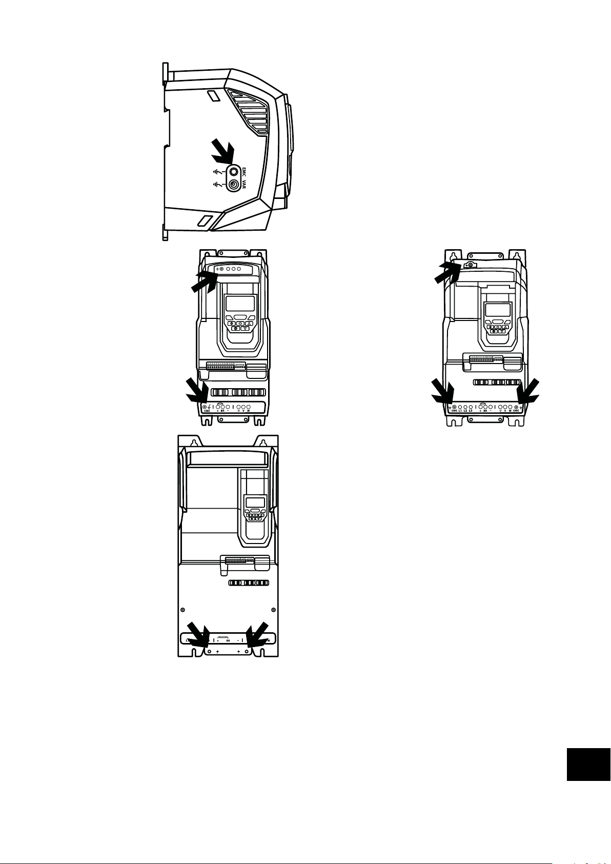
Frame Sizes 2 & 3
The EMC Filter and
Varistor disconnect screws
are located on the left
side of the product when
viewed from the front.
Remove both screws
completely
Frame Size 4
Frame Size 4 units have
EMC Filter disconnection
points only located on the
front face of the unit as
shown.
Frame Size 6A/6B
Frame Size 6A/6B
units have EMC Filter
disconnection points only
located on the front face of
the unit as shown.
EMC L1 L2 L3
Frame Size 5
Frame Size 5 units have
EMC Filter disconnection
points only located on the
front face of the unit as
shown.
10.6.2. IP55 & IP66 Models
These models require disassembly in order to disconnect the EMC filter. Disconnection should be carried out only by Invertek Drives
Approved Service Partners.
Version 3.04 | Optidrive P2 User Guide | 77www.invertekdrives.com
Technical Data
10
Page 78

11. Troubleshooting
11.1. Fault Messages
Troubleshooting
Fault
Code
-
-
-
-
.-
PS-P
-
-
-
-
P-e
No. OLED Message
00 No Fault Displayed in P0-13 if no faults are recorded in the log.
01 Brake channel over
02 Brake resistor overload The drive software has determined that the brake resistor is overloaded, and trips to protect the
03 Over current trip Fault Occurs on Drive Enable
04 Drive has tripped
05 Hardware Over Current Check the wiring to motor and the motor for phase to phase and phase to earth short circuits.
06 Over voltage on DC
07 Under voltage on DC
08 Heatsink over
09 Under temperature Trip occurs when ambient temperature is less than -10°C. The temperature must be raised over
10 Factory Default
Description
current
on overload after
delivering >100% of
value in P1-08 for a
period of time.
bus
bus
temperature
parameters have been
loaded
Ensure the connected brake resistor is above the minimum permissible level for the drive – refer to
the ratings shown in section 10.2. Input/Output Power and Current Ratings.
Check the brake resistor and wiring for possible short circuits.
resistor. Always ensure the brake resistor is being operated within its designed parameter before
making any parameter or system changes.
To reduce the load on the resistor, increase the deceleration time, reduce the load inertia or add
further brake resistors in parallel, observing the minimum resistance value for the drive in use.
Check the motor and motor connection cable for phase – phase and phase – earth short circuits.
Check the load mechanically for a jam, blockage or stalled condition.
Ensure the motor nameplate parameters are correctly entered, P1-07, P1-08, P1-09.
If operating in Vector mode (P4-01 – 0 or 1), also check the motor power factor in P4-05 and
ensure an autotune has been successfully completed for the connected motor.
Reduced the Boost voltage setting in P1-11.
Increase the ramp up time in P1-03.
If the connected motor has a holding brake, ensure the brake is correctly connected and controlled,
and is releasing correctly.
Fault Occurs When Running
If operating in Vector mode (P4-01 – 0 or 1), reduce the speed loop gain in P4-03.
Check to see when the decimal points are flashing (drive in overload) and either increase
acceleration rate or reduce the load.
Check motor cable length is within the limit specified for the relevant drive in section 10.2.
Ensure the motor nameplate parameters are correctly entered in P1-07, P1-08, and P1-09.
If operating in Vector mode (P4-01 – 0 or 1), also check the motor power factor in P4-05 and
ensure an autotune has been successfully completed for the connected motor.
Check the load mechanically to ensure it is free, and that no jams, blockages or other mechanical
faults exist.
Disconnect the motor and motor cable and retest. If the drive trips with no motor connected, it must
be replaced and the system fully checked and retested before a replacement unit is installed.
The value of the DC Bus Voltage can be displayed in P0-20.
A historical log is stored at 256ms intervals prior to a trip in parameter P0-36.
This fault is generally caused by excessive regenerative energy being transferred from the load
back to the drive. When a high inertia or over hauling type load is connected.
If the fault occurs on stopping or during deceleration, increase the deceleration ramp time P1-04 or
connect a suitable brake resistor to the drive.
If operating in Vector Mode, reduce the speed loop gain P4-03.
If operating in PID control, ensure that ramps are active by reducing P3-11.
This occurs routinely when power is switched off.
If it occurs during running, check the incoming supply voltage, and all connections into the drive,
fuses, contactors etc.
The heatsink temperature can be displayed in P0-21.
A historical log is stored at 30 second intervals prior to a trip in parameter P0-38.
Check the drive ambient temperature.
Ensure the drive internal cooling fan is operating.
Ensure that the required space around the drive as shown in sections 3.5. Mechanical Dimensions
and Weight to 3.9. Guidelines for Mounting (IP66 Units) has been observed, and that the cooling
airflow path to and from the drive is not restricted.
Reduce the effective switching frequency setting in parameter P2-24.
Reduce the load on the motor / drive.
-10°C in order to start the drive.
Press STOP key, the drive is now ready to be configured for the required application.
Corrective Action
11
78 | Optidrive P2 User Guide | Version 3.04 www.invertekdrives.com
Page 79

Fault
Code
-
S-
-
P-
h -
h-
-
-
-
-e
-P
-
-he
-q
-q
-
S-
-
SP-
-
-
-
-
No. OLED Message
11 External trip E-trip requested on control input terminals. Some settings of P1-13 require a normally closed
12 Communications Fault Communications lost with PC or remote keypad. Check the cables and connections to external
13 Excessive DC ripple The DC Bus Ripple Voltage level can be displayed in parameter P0-16.
14 Input phase loss Drive intended for use with a 3 phase supply, one input phase has been disconnected or lost.
15 Instantaneous over
16 Faulty thermistor on
17 Internal memory fault Parameters not saved, defaults reloaded.
18 4-20mA Signal Lost The reference signal on Analog Input 1 or 2 (Terminals 6 or 10) has dropped below the minimum
19 Internal memory fault Parameters not saved, defaults reloaded.
20 User Parameter Default User Parameter defaults have been loaded. Press the Stop key.
21 Motor PTC Over
22 Cooling Fan Fault Check and if necessary, replace the drive internal cooling fan.
23 Ambient Temperature
24 Maximum Torque Limit
25 Output Torque Too Low Active only when hoist brake control is enabled P2-18 = 8. The torque developed prior to releasing
26 Drive output fault Drive output fault.
29 Internal STO circuit Error Refer to your Invertek Sales Partner.
30 Encoder Feedback Fault Encoder communication /data loss.
31 Speed Error Speed Error. The error between the measured encoder feedback speed or the estimated rotor
32 Encoder Feedback Fault Incorrect Encoder PPR count set in parameter P6-06.
33 Encoder Feedback Fault Encoder Channel A Fault.
34 Encoder Feedback Fault Encoder Channel B Fault.
35 Encoder Feedback Fault Encoder Channels A & B Fault.
Description
current on drive output
heatsink
Temperature
High
Exceeded
contact to provide an external means of tripping the drive in the event that an external device
develops a fault. If a motor thermistor is connected check if the motor is too hot.
devices.
A historical log is stored at 20ms intervals prior to a trip in parameter P0-37.
Check all three supply phases are present and within the 3% supply voltage level imbalance
tolerance.
Reduce the motor load.
If the fault persists, contact your local Invertek Drives Sales Partner.
Refer to fault 3 above.
Refer to your Invertek Sales Partner.
Try again. If problem recurs, refer to your IDL Authorised Distributor.
threshold of 3mA. Check the signal source and wiring to the Optidrive terminals.
Try again. If problem recurs, refer to your IDL Authorised Distributor.
The connected motor PTC device has caused the drive to trip.
The measured temperature around the drive is above the operating limit of the drive.
Ensure the drive internal cooling fan is operating.
Ensure that the required space around the drive as shown in sections 3.5. Mechanical Dimensions
and Weight to 3.9. Guidelines for Mounting (IP66 Units) has been observed, and that the cooling
airflow path to and from the drive is not restricted.
Increase the cooling airflow to the drive.
Reduce the effective switching frequency setting in parameter P2-24.
Reduce the load on the motor / drive.
The output torque limit has exceeded the drive capacity or trip threshold.
Reduce the motor load, or increase the acceleration time.
the motor holding brake is below the preset threshold. Contact your local Invertek Sales Partner for
further information on using the Optidrive P2 in hoist applications.
speed is greater than the pre-set limit allowed. In Hoist Mode Operation, this protection is always
active even if no encoder is fitted. The motor speed deviates from the intended motor speed by an
error greater than that set in the limit parameter P6-07.
Corrective Action
Troubleshooting
11
Version 3.04 | Optidrive P2 User Guide | 79www.invertekdrives.com
Page 80

Fault
Code
-
-
-
-
-
Ph-Sq
-Ph
S-
S-
S-
S-
No. OLED Message
40 Autotune Failed Measured motor stator resistance varies between phases. Ensure the motor is correctly connected
41 Measured motor stator resistance is too large. Ensure the motor is correctly connected and free
42 Measured motor inductance is too low. Ensure the motor is correctly connected and free from
43 Measured motor inductance is too large. Ensure the motor is correctly connected and free from
44 Measured motor parameters are not convergent. Ensure the motor is correctly connected and free
45 Incorrect Supply Phase
49 Output Phase Loss One of the motor output phases is not connected to the drive.
50 Modbus Comms fault A valid Modbus telegram has not been received within the watchdog time limit set in P5-05.
51 CAN Open comms trip A valid CAN open telegram has not been received within the watchdog time limit set in P5-05.
52 Communications Option
53 IO card comms trip Internal communication to the inserted Option Module has been lost.
Description
Sequence
Module Fault
and free from faults. Check the windings for correct resistance and balance.
from faults. Check that the power rating corresponds to the power rating of the connected drive.
faults.
faults. Check that the power rating corresponds to the power rating of the connected drive.
from faults. Check that the power rating corresponds to the power rating of the connected drive.
Applies to Frame Size 8 drives only, indicates that the incoming power supply phase sequence is
incorrect. Any 2 phases may be swapped.
Check the network master / PLC is still operating.
Check the connection cables.
Increase the value of P5-05 to a suitable level.
Check the network master / PLC is still operating.
Check the connection cables.
Increase the value of P5-05 to a suitable level.
Internal communication to the inserted Communication Option Module has been lost.
Check the module is correctly inserted.
Check the module is correctly inserted.
Corrective Action
Ñ82-P2I66-IN_V3.04|Ó
82-P2I66-IN_V3.04
Invertek Drives Ltd. Offa's Dyke Business Park, Welshpool, Powys SY21 8JF United Kingdom
Tel: +44 (0)1938 556868 Fax: +44 (0)1938 556869
www.invertekdrives.com
 Loading...