

Page 1
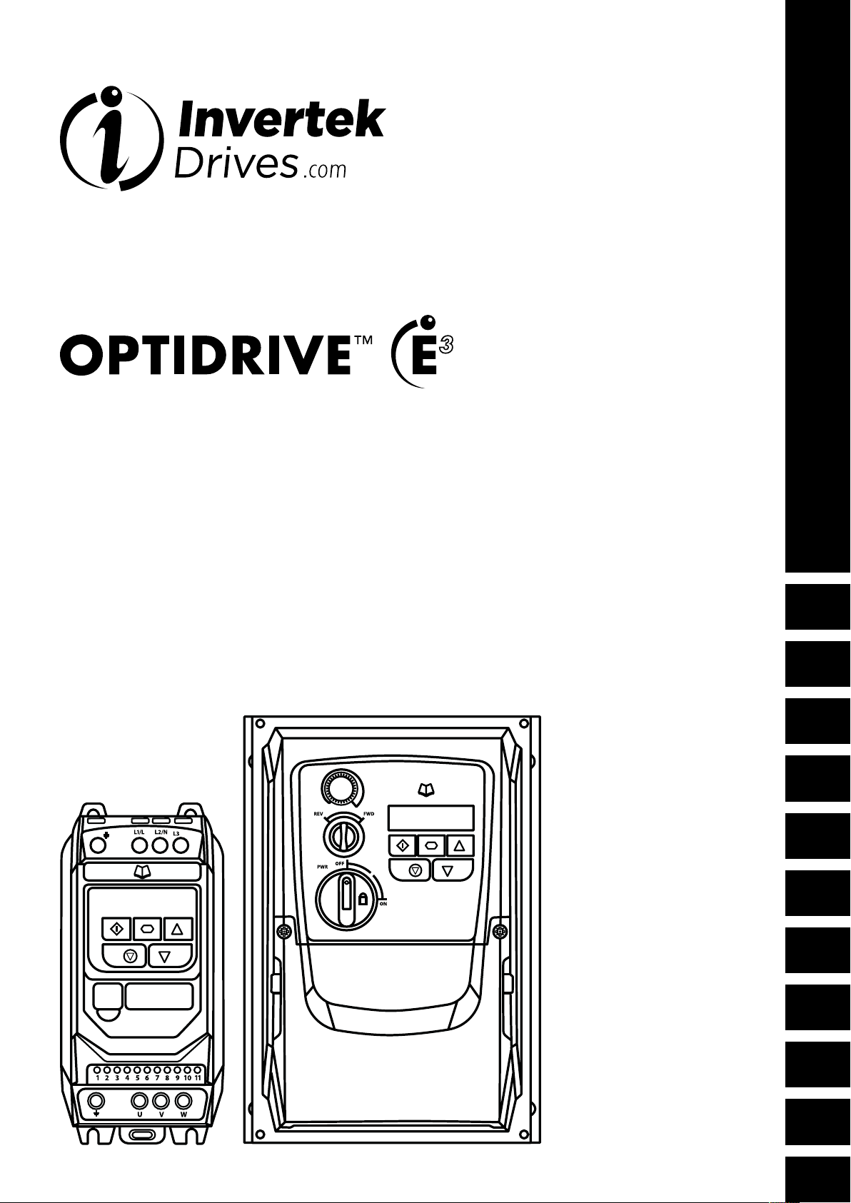
AC Variable Speed Drive
IP20 & IP66 (NEMA 4X)
User Manual
Troubleshooting
0.37kW – 22kW / 0.5HP – 30HP
110 – 480V 3 Phase Input
Quick Start Up
General Information
and Ratings
Mechanical Installation
Power & Control Wiring
0
Operation
Parameters
1
1
2
2
3
3
4
4
5
5
6
6
Analog and Digital Input
Macro Configurations
Modbus RTU
Communications
Technical Data
Troubleshooting
7
7
8
8
9
9
10
10
Page 2

1. Quick Start Up ................................4
1.1. Important Safety Information. . . . . . . . . . . . . . . . . . . . . . . . . . . . 4
1.2. Quick Start Process ...................................5
1.3. Installation Following a Period of Storage ................5
2. General Information and Ratings ................7
2.1. Identifying the Drive by Model Number ..................7
2.2. Drive Model Numbers ................................7
3. Mechanical Installation ........................9
3.1. General ............................................9
3.2. UL Compliant Installation ..............................9
3.3. Mechanical Dimensions and Mounting – IP20 Open Units
...9
3.4. Guidelines for Enclosure Mounting – IP20 Units .........10
3.5. Mechanical Dimensions – IP66 (Nema 4X) Enclosed Units
. . 11
3.6. Guidelines for mounting (IP66 Units) ................... 12
3.7. Gland Plate and Lock Off ............................12
3.8. Removing the Terminal Cover .........................13
3.9. Routine Maintenance ................................13
4. Power & Control Wiring .......................14
4.1. Connection Diagram .................................14
4.2. Protective Earth (PE) Connection .......................15
4.3. Incoming Power Connection ..........................15
4.4. Motor Connection ..................................16
4.5. Motor Terminal Box Connections ......................16
4.6. Control Terminal Wiring ..............................16
4.7. Using the REV/0/FWD Selector Switch (Switched Version
Only) .................................................17
4.8. Control Terminal Connections .........................17
4.9. Motor Thermal Overload Protection ....................18
4.10. EMC Compliant Installation ..........................19
4.11. Optional Brake Resistor ..............................19
6. Parameters ............................... 22
6.1. Standard Parameters ............................... 22
6.2. Extended Parameters .............................. 24
6.3. Advanced Parameters .............................29
6.4. P-00 Read Only Status Parameters ...................30
7. Analog and Digital Input Macro Configurations
...31
7.1. Overview ........................................ 31
7.2. Macro Functions Guide Key ........................ 31
7.3. Macro Functions – Terminal Mode (P-12 = 0) ..........32
7.4. Macro Functions - Keypad Mode (P-12 = 1 or 2) ......33
7.5. Macro Functions - Fieldbus Control Mode (P-12 = 3, 4, 7, 8
or 9) ................................................33
7.6. Macro Functions - User PI Control Mode (P-12 = 5 or 6)
. . 34
7.7. Fire Mode ........................................34
7.8. Example Connection Diagrams ......................35
8. Modbus RTU Communications ................ 36
8.1. Introduction .......................................36
8.2. Modbus RTU Specification .........................36
8.3. RJ45 Connector Configuration ......................36
8.4. Modbus Register Map ..............................11
9. Technical Data ..............................37
9.1. Environmental ..................................... 37
9.2. Rating Tables ..................................... 37
9.3. Single Phase Operation of Three Phase Drives ......... 37
9.4. Additional Information for UL Compliance .............38
9.5. EMC Filter Disconnect .............................38
10. Troubleshooting .......................... 39
10.1. Fault Code Messages .............................39
5. Operation ..................................20
5.1. Managing the Keypad ...............................20
5.2. Operating Displays ..................................20
5.3. Changing Parameters ................................20
5.4. Read Only Parameter Access .........................21
5.5. Resetting Parameters .................................21
5.6. Resetting a Fault .....................................21
2 | Optidrive ODE-3 User Guide | Version 2.00 www.invertekdrives.com
Page 3

Declaration of Conformity
Invertek Drives Ltd hereby states that the Optidrive ODE-3 product range conforms to the relevant safety provisions of the following
council directives:
2014/30/EU (EMC) and 2014/35/EU (LVD)
Designed and manufacture is in accordance with the following harmonised European standards:
EN 61800-5-1: 2007 Adjustable speed electrical power drive systems. Safety
requirements. Electrical, thermal and energy.
EN 61800-3: 2004 /A1 2012 Adjustable speed electrical power drive systems. EMC
requirements and specific test methods
EN 55011: 2007 Limits and Methods of measurement of radio disturbance
characteristics of industrial, scientific and medical (ISM) radiofrequency equipment (EMC)
EN60529: 1992 Specifications for degrees of protection provided by enclosures
Electromagnetic Compatibility
All Optidrives are designed with high standards of EMC in mind. All versions suitable for operation on Single Phase 230 volt and
Three Phase 400 volt supplies and intended for use within the European Union are fitted with an internal EMC filter. This EMC filter
is designed to reduce the conducted emissions back into the mains supply via the power cables for compliance with the above
harmonised European standards.
It is the responsibility of the installer to ensure that the equipment or system into which the product is incorporated complies with the
EMC legislation of the country of use, and the relevant category. Within the European Union, equipment into which this product is
incorporated must comply with the EMC Directive 2004/108/EC. This User Guide provides guidance to ensure that the applicable
standards may be achieved.
Copyright Invertek Drives Ltd © 2016
All rights reserved. No part of this User Guide may be reproduced or transmitted in any form or by any means, electrical or mechanical
including photocopying, recording or by any information storage or retrieval system without permission in writing from the publisher.
2 Year Warranty
All Invertek Optidrive units carry a 2 year warranty against manufacturing defects from the date of manufacture. The manufacturer
accepts no liability for any damage caused during or resulting from transport, receipt of delivery, installation or commissioning. The
manufacturer also accepts no liability for damage or consequences resulting from inappropriate, negligent or incorrect installation,
incorrect adjustment of the operating parameters of the drive, incorrect matching of the drive to the motor, incorrect installation,
unacceptable dust, moisture, corrosive substances, excessive vibration or ambient temperatures outside of the design specification.
The local distributor may offer different terms and conditions at their discretion, and in all cases concerning warranty, the local
distributor should be contacted first.
This user guide is the “original instructions” document. All non-English versions are translations of the
“original instructions”.
The contents of this User Guide are believed to be correct at the time of printing. In the interest of a commitment to a policy of
continuous improvement, the manufacturer reserves the right to change the specification of the product or its performance or the
contents of the User Guide without notice.
This User Guide is for use with version 3.05 Firmware
User Guide Revision 2.00
Invertek Drives Ltd adopts a policy of continuous improvement and whilst every effort has been made to provide accurate and up to
date information, the information contained in this User Guide should be used for guidance purposes only and does not form the part
of any contract.
This manual is intended as a guide for proper installation. Invertek Drives Ltd cannot assume responsibility for the compliance
or the non-compliance to any code, national, local or otherwise, for the proper installation of this drive or associated
equipment. A hazard of personal injury and/or equipment damage exists if codes are ignored during installation.
This Optidrive contains high voltage capacitors that take time to discharge after removal of the main supply. Before
working on the drive, ensure isolation of the main supply from line inputs. Wait ten (10) minutes for the capacitors to
discharge to safe voltage levels. Failure to observe this precaution could result in severe bodily injury or loss of life.
Only qualified electrical personnel familiar with the construction and operation of this equipment and the hazards involved
should install, adjust, operate, or service this equipment. Read and understand this manual and other applicable manuals
in their entirety before proceeding. Failure to observe this precaution could result in severe bodily injury or loss of life.
Version 2.00 | Optidrive ODE-3 User Guide | 3www.invertekdrives.com
Page 4
Quick Start Up
1
1. Quick Start Up
1.1. Important Safety Information
Please read the IMPORTANT SAFETY INFORMATION below, and all Warning and Caution information elsewhere.
Danger: Indicates a risk of electric shock, which,
if not avoided, could result in damage to the
equipment and possible injury or death.
This variable speed drive product (Optidrive) is intended for
professional incorporation into complete equipment or systems
as part of a fixed installation. If installed incorrectly it may present
a safety hazard. The Optidrive uses high voltages and currents,
carries a high level of stored electrical energy, and is used to
control mechanical plant that may cause injury. Close attention
is required to system design and electrical installation to avoid
hazards in either normal operation or in the event of equipment
malfunction. Only qualified electricians are allowed to install
and maintain this product.
System design, installation, commissioning and maintenance
must be carried out only by personnel who have the necessary
training and experience. They must carefully read this safety
information and the instructions in this Guide and follow all
information regarding transport, storage, installation and use of
the Optidrive, including the specified environmental limitations.
Do not perform any flash test or voltage withstand test on the
Optidrive. Any electrical measurements required should be
carried out with the Optidrive disconnected.
Electric shock hazard! Disconnect and ISOLATE the Optidrive
before attempting any work on it. High voltages are present
at the terminals and within the drive for up to 10 minutes after
disconnection of the electrical supply. Always ensure by using a
suitable multimeter that no voltage is present on any drive power
terminals prior to commencing any work.
Where supply to the drive is through a plug and socket
connector, do not disconnect until 10 minutes have elapsed after
turning off the supply.
Ensure correct earthing connections. The earth cable must
be sufficient to carry the maximum supply fault current which
normally will be limited by the fuses or MCB. Suitably rated
fuses or MCB should be fitted in the mains supply to the drive,
according to any local legislation or codes.
Ensure correct earthing connections and cable selection as per
defined by local legislation or codes. The drive may have a
leakage current of greater than 3.5mA; furthermore the earth
cable must be sufficient to carry the maximum supply fault current
which normally will be limited by the fuses or MCB. Suitably
rated fuses or MCB should be fitted in the mains supply to the
drive, according to any local legislation or codes.
Do not carry out any work on the drive control cables whilst
power is applied to the drive or to the external control circuits.
Within the European Union, all machinery in which this product
is used must comply with Directive 2006/42/EC, Safety of
Machinery. In particular, the machine manufacturer is responsible
for providing a main switch and ensuring the electrical equipment
complies with EN60204-1.
The level of integrity offered by the Optidrive control input
functions – for example stop/start, forward/reverse and
maximum speed is not sufficient for use in safety-critical
applications without independent channels of protection. All
applications where malfunction could cause injury or loss of
life must be subject to a risk assessment and further protection
provided where needed.
The driven motor can start at power up if the enable input signal
is present.
The STOP function does not remove potentially lethal high
voltages. ISOLATE the drive and wait 10 minutes before starting
any work on it. Never carry out any work on the Drive, Motor or
Motor cable whilst the input power is still applied.
The Optidrive can be programmed to operate the driven motor
at speeds above or below the speed achieved when connecting
the motor directly to the mains supply. Obtain confirmation from
the manufacturers of the motor and the driven machine about
suitability for operation over the intended speed range prior to
machine start up.
Do not activate the automatic fault reset function on any systems
whereby this may cause a potentially dangerous situation.
IP20 drives must be installed in a pollution degree 2
environment, mounted in a cabinet with IP54 or better.
Optidrives are intended for indoor use only.
When mounting the drive, ensure that sufficient cooling is provided.
Do not carry out drilling operations with the drive in place, dust
and swarf from drilling may lead to damage.
The entry of conductive or flammable foreign bodies should be
prevented. Flammable material should not be placed close to
the drive
Relative humidity must be less than 95% (non-condensing).
Ensure that the supply voltage, frequency and no. of phases (1 or
3 phase) correspond to the rating of the Optidrive as delivered.
Never connect the mains power supply to the Output terminals
U, V, W.
Do not install any type of automatic switchgear between the
drive and the motor.
Wherever control cabling is close to power cabling, maintain
a minimum separation of 100 mm and arrange crossings
at 90 degrees. Ensure that all terminals are tightened to the
appropriate torque setting.
Do not attempt to carry out any repair of the Optidrive. In
the case of suspected fault or malfunction, contact your local
Invertek Drives Sales Partner for further assistance.
Danger: Indicates a potentially hazardous situation
other than electrical, which if not avoided, could
result in damage to property.
4 | Optidrive ODE-3 User Guide | Version 2.00 www.invertekdrives.com
Page 5

1.2. Quick Start Process
Step Action Page
1 Identify the Enclosure Type, Model Type and ratings of
your drive from the model code on the label. In particular
- Check the voltage rating suits the incoming supply
- Check the output current capacity meets or exceeds the
full load current for the intended motor
2 Unpack and check the drive. Notify the supplier and
shipper immediately of any damage.
3 Ensure correct ambient and environmental conditions for
the drive are met by the proposed mounting location.
4 Install the drive in a suitable cabinet (IP20 Units) ensuring
suitable cooling air is available. Mount the drive to the
wall or machine (IP66).
5 Select the correct power and motor cables according
to local wiring regulations or code, noting the maximum
permissible sizes
6 If the supply type is IT or corner grounded, disconnect the
EMC filter before connecting the supply.
7 Check the supply cable and motor cable for faults or short
circuits.
8 Route the cables
9 Check that the intended motor is suitable for use, noting
any precautions recommended by the supplier or
manufacturer.
10 Check the motor terminal box for correct Star or Delta
configuration where applicable
11 Ensure wiring protection is providing, by installing a
suitable circuit breaker or fuses in the incoming supply line
12 Connect the power cables, especially ensuring the
protective earth connection is made
13 Connect the control cables as required for the application 4.6. Control Terminal Wiring
14 Thoroughly check the installation and wiring
15 Commission the drive parameters 5.1. Managing the Keypad
2.1. Identifying the Drive by Model Number 7
9.1. Environmental 37
3.1. General
3.3. Mechanical Dimensions and Mounting – IP20
Open Units
3.4. Guidelines for Enclosure Mounting – IP20 Units
3.5. Mechanical Dimensions – IP66 (Nema 4X)
Enclosed Units
3.6. Guidelines for mounting (IP66 Units)
9.2. Rating Tables 37
9.5. EMC Filter Disconnect 38
4.10. EMC Compliant Installation 19
4.5. Motor Terminal Box Connections 16
4.3.2. Fuse / Circuit Breaker Selection
9.2. Rating Tables
4.1. Connection Diagram
4.2. Protective Earth (PE) Connection
4.3. Incoming Power Connection
4.4. Motor Connection
4.10. EMC Compliant Installation
7. Analog and Digital Input Macro Configurations
7.8. Example Connection Diagrams
6. Parameters
9
9
10
11
Quick Start Up
12
1
15
37
14
15
15
16
16
19
31
35
20
22
1.3. Installation Following a Period of Storage
If the drive has not been powered, either unused or in storage, the DC Link Capacitors require reforming before power may be
connected to the drive. Refer to your local sales partner for information regarding the correct procedure.
Version 2.00 | Optidrive ODE-3 User Guide | 5www.invertekdrives.com
Page 6
Quick Start Up
1.4. Quick Start Overview
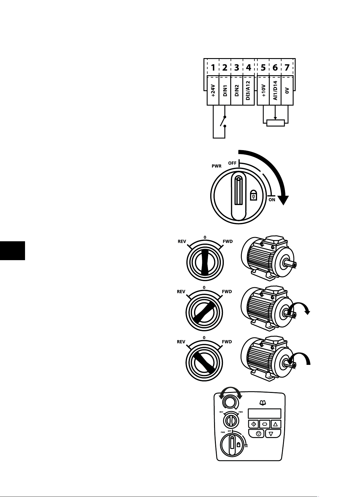
Quick Start – IP20 & IP66 Non Switched
Connect a Start / Stop switch between control
terminals 1 & 2
o Close the Switch to Start
o Open to Stop
Connect a potentiometer (5k – 10kΩ) between terminals 5,
6 and 7 as shown
o Adjust the potentiometer to vary the speed from P-02
(0Hz default) to P-01 (50 / 60 Hz default)
Quick Start – IP66 Switched
Switch the mains power on to the unit using the built in isolator
switch on the front panel.
1
The OFF/REV/FWD will enable the output and control the
direction of rotation of the motor.
0
The potentiometer will control the motor shaft rotational speed.
6 | Optidrive ODE-3 User Guide | Version 2.00 www.invertekdrives.com
Page 7
2. General Information and Ratings
This chapter contains information about the Optidrive E3 including how to identify the drive.
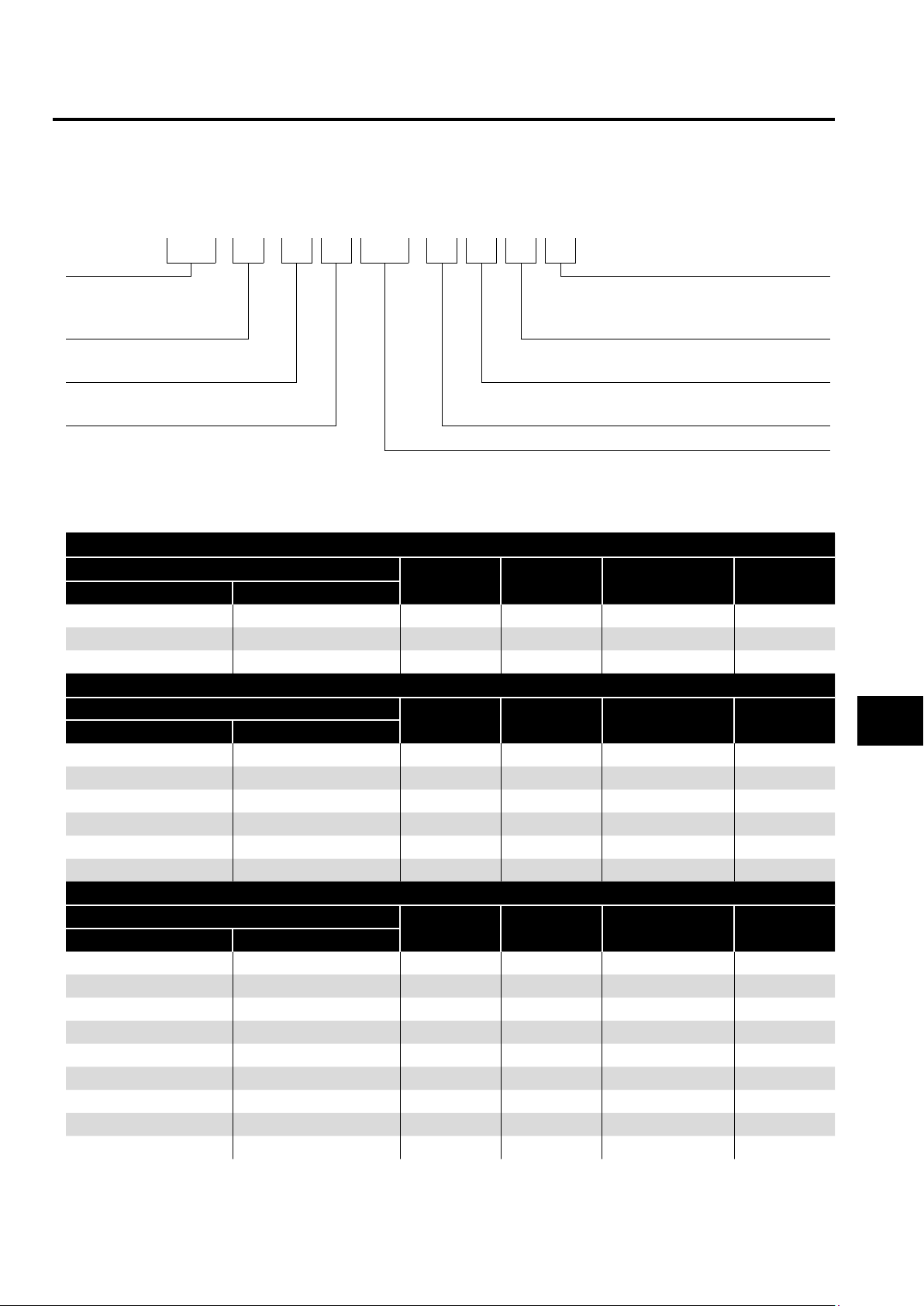
2.1. Identifying the Drive by Model Number
Each drive can be identified by its model number, as shown in the table below. The model number is on the shipping label and the
drive nameplate. The model number includes the drive and any options.
ODE - 3 - 1 2 0021 - 1 F 1 2
Product Family IP Rating 2 = IP20
X = IP66 Non Switched
Y = IP66 Switched
Generation Dynamic Brake
Transistor
Frame Size Filter Type 0 = No Filter
Input Voltage 1 = 110 – 115 No. Of Input Phases
2 = 200 – 240
4 = 380 – 480
2.2. Drive Model Numbers
110 – 115V ± 10% - 1 Phase Input – 3 Phase 230V Output (Voltage Doubler)
Model Number
With Filter Without Filter
N/A ODE-3-110023-101# 0.5 2.3 1
N/A ODE-3-110043-101# 1 4.3 1
N/A ODE-3-210058-104# 1.5 5.8 2
200 – 240V ± 10% - 1 Phase Input – 3 Phase Output
Model Number
With Filter Without Filter
ODE-3-120023-1F1# ODE-3-120023-101# 0.37 0.5 2.3 1
ODE-3-120043-1F1# ODE-3-120043-101# 0.75 1 4.3 1
ODE-3-120070-1F1# ODE-3-120070-101# 1.5 2 7 1
ODE-3-220070-1F4# ODE-3-220070-104# 1.5 2 7 2
ODE-3-220105-1F4# ODE-3-220105-104# 2.2 3 10.5 2
N/A ODE-3-320153-104# 4.0 5 15 .3 3
200 – 240V ± 10% - 3 Phase Input – 3 Phase Output
Model Number
With Filter Without Filter
N/A ODE-3-120023-301# 0.37 0.5 2.3 1
N/A ODE-3-120043-301# 0. 75 1 4.3 1
N/A ODE-3-120070-301# 1.5 2 7 1
ODE-3-220070-3F4# ODE-3-220070-304# 1.5 2 7 2
ODE-3-220105-3F4# ODE-3-220105-304# 2.2 3 10.5 2
ODE-3-320180-3F4# ODE-3-320180-304# 4.0 5 18 3
ODE-3-320240-3F4# ODE-3-320240-304# 5.5 7. 5 24 3
ODE-3-420300-3F4# ODE-3-420300-304# 7. 5 10 30 4
ODE-3-420460-3F4# ODE-3-420460-304# 11 15 46 4
kW HP
kW HP
kW HP
Output Current
Output Current
Output Current
1 = Not Fitted
4 = Internal Transistor
F = Internal EMC Filter
Output Current x 10
(A)
(A)
(A)
Frame Size
Frame Size
Frame Size
General Information and Ratings
2
Version 2.00 | Optidrive ODE-3 User Guide | 7www.invertekdrives.com
Page 8

380 – 480V ± 10% - 3 Phase Input – 3 Phase Output
Model Number
With Filter Without Filter
ODE-3-140022-3F1# ODE-3-140022-301# 0. 75 1 2.2 1
ODE-3-140041-3F1# ODE-3-140041-301# 1.5 2 4 .1 1
ODE-3-240041-3F4# ODE-3-240041-304# 1. 5 2 4 .1 2
ODE-3-240058-3F4# ODE-3-240058-304# 2.2 3 5.8 2
General Information and Ratings
ODE-3-240095-3F4# ODE-3-240095-304# 4 5 9.5 2
ODE-3-340140-3F4# ODE-3-340140-304# 5.5 7. 5 14 3
ODE-3-340180-3F4# ODE-3-340180-304# 7.5 10 18 3
ODE-3-340240-3F42 ODE-3-340240-3042 11 15 24 3
ODE-3-440300-3F42 ODE-3-440300-3042 15 20 30 4
ODE-3-440390-3F42 ODE-3-440390-3042 18.5 25 39 4
ODE-3-440460-3F42 ODE-3-440460-3042 22 30 46 4
For IP20 units, replace ‘#’ with ‘2’
NOTE
For IP66 Non Switched Units, replace ‘#’ with ‘X’
For IP66 Switched Units, replace ‘#’ with ‘Y’
kW HP
Output Current
(A)
Frame Size
2
8 | Optidrive ODE-3 User Guide | Version 2.00 www.invertekdrives.com
Page 9
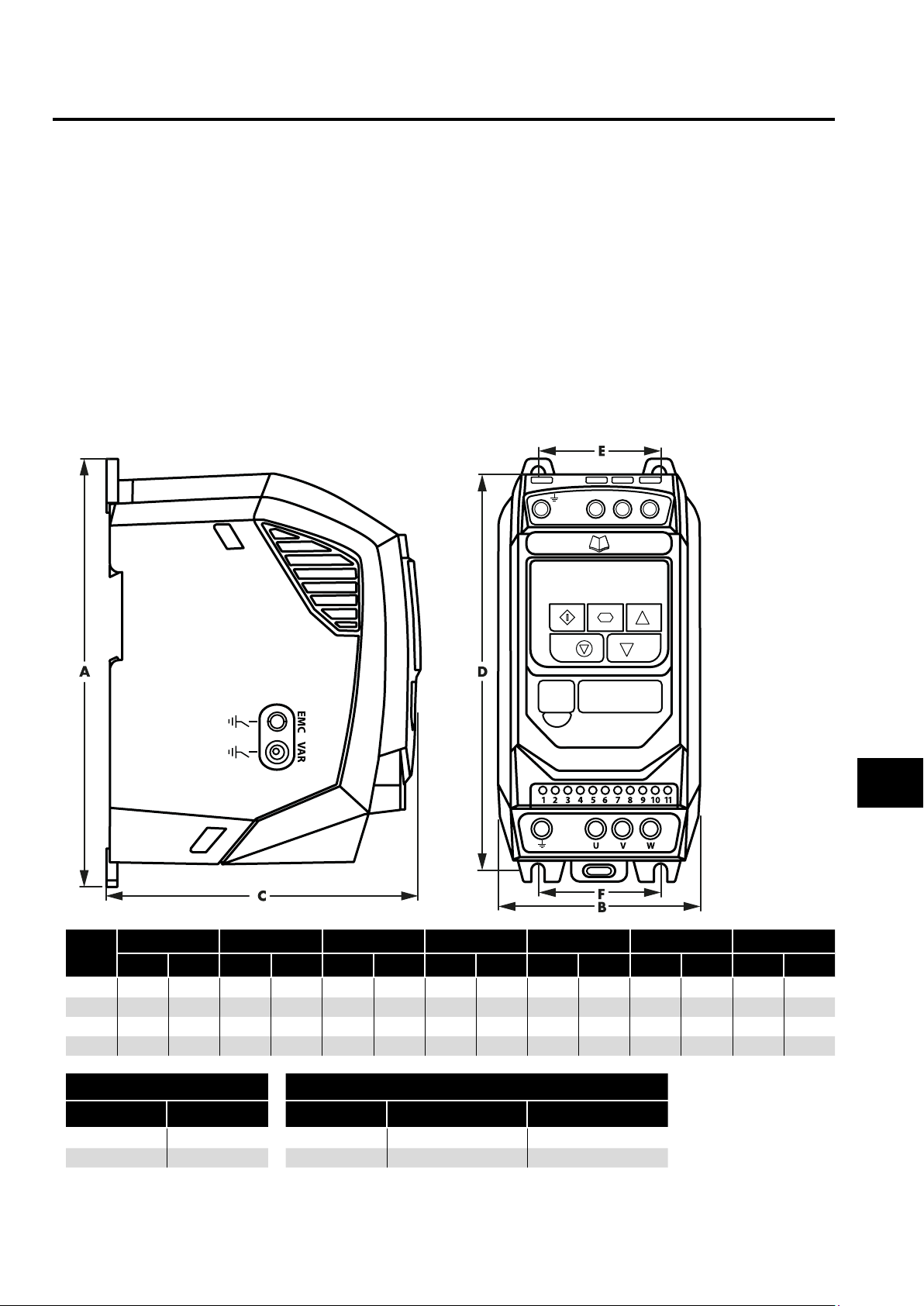
3. Mechanical Installation
3.1. General
The Optidrive should be mounted in a vertical position only, on a flat, flame resistant, vibration free mounting using the integral
mounting holes or DIN Rail clip (Frame Sizes 1 and 2 only).
IP20 Optidrives must be installed in a pollution degree 1 or 2 environment only.
Do not mount flammable material close to the Optidrive.
Ensure that the minimum cooling air gaps, as detailed in section 3.5. Mechanical Dimensions – IP66 (Nema 4X) Enclosed Units
and 3.7. Gland Plate and Lock Off are left clear.
Ensure that the ambient temperature range does not exceed the permissible limits for the Optidrive given in section 9.1.
Environmental.
Provide suitable clean, moisture and contaminant free cooling air sufficient to fulfil the cooling requirements of the Optidrive.
3.2. UL Compliant Installation
Refer to section 9.4. Additional Information for UL Compliance on page 38 for Additional Information for UL Compliance.
3.3. Mechanical Dimensions and Mounting – IP20 Open Units
L1/LL3L2/N
Mechanical Installation
Drive
Size
1 173 6.81 83 3.27 123 4.84 162 6.38 50 1.97 50 1.97 1.0 1.0
2 2 21 8.70 11 0 4.33 15 0 5 . 91 209 8.23 63 2.48 63 2.48 1.7 1.7
3 2 61 10.28 131 5.16 175 6.89 247 9. 72 80 3 .15 80 3 .15 3.2 3.2
4 420 16.54 171 6. 73 212 8.35 400 15. 75 125 4.92 12 5 4.92 9.1 9.1
Frame Size Frame Size Control Terminals Power Terminals
1 - 3 4 x M5 (#8) 1 - 3 0.5 Nm (4.5 lb-in) 1 Nm (9 lb-in)
4 4 x M8 4 0.5 Nm (4.5 lb-in) 2 Nm (18 lb-in)
A B C D E F Weight
mm in mm in mm in mm in mm in mm in Kg Ib
Mounting Bolts Tightening Torques
3
Version 2.00 | Optidrive ODE-3 User Guide | 9www.invertekdrives.com
Page 10
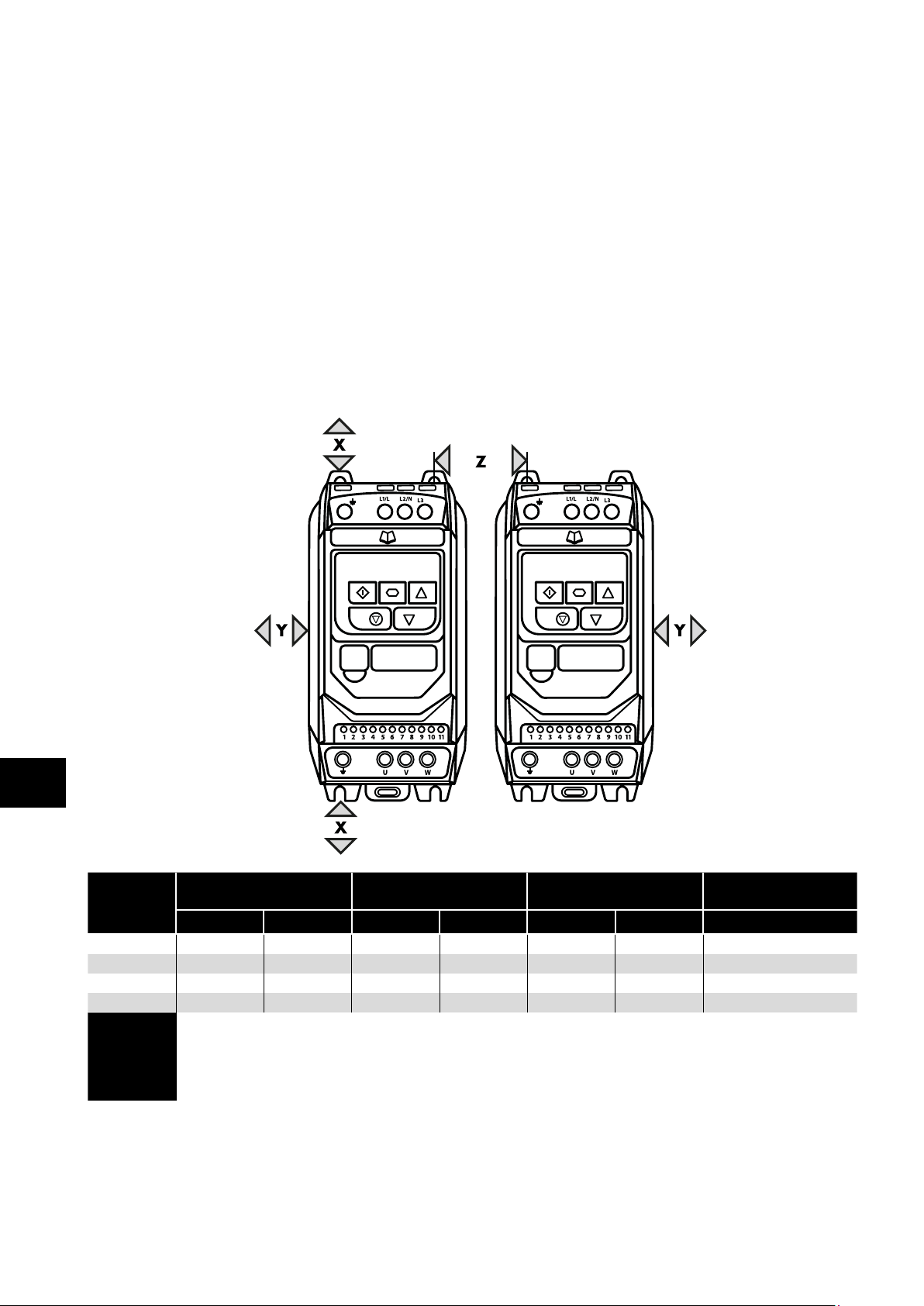
3.4. Guidelines for Enclosure Mounting – IP20 Units
IP20 drives are suitable for use in pollution degree 1 environments, according to IEC-664-1. For pollution degree 2 or higher
environments, drives should be mounted in a suitable control cabinet with sufficient ingress protection to maintain a pollution
degree 1 environment around the drive.
Enclosures should be made from a thermally conductive material.
Ensure the minimum air gap clearances around the drive as shown below are observed when mounting the drive.
Where ventilated enclosures are used, there should be venting above the drive and below the drive to ensure good air circulation.
Air should be drawn in below the drive and expelled above the drive.
In any environments where the conditions require it, the enclosure must be designed to protect the Optidrive against ingress of
airborne dust, corrosive gases or liquids, conductive contaminants (such as condensation, carbon dust, and metallic particles) and
sprays or splashing water from all directions.
High moisture, salt or chemical content environments should use a suitably sealed (non-vented) enclosure.
The enclosure design and layout should ensure that the adequate ventilation paths and clearances are left to allow air to circulate
through the drive heatsink. Invertek Drives recommend the following minimum sizes for drives mounted in non-ventilated metallic
enclosures:
Mechanical Installation
3
X
Drive Size
1 50 1.97 50 1.97 33 1.30 11
2 75 2.95 50 1.97 46 1 . 81 22
3 100 3.94 50 1.97 52 2.05 60
4 100 3.94 50 1.97 52 2.05 12 0
Above & Below
mm in mm in mm in CFM (ft3/min)
Y
Either Side
Z
Between
Dimension Z assumes that the drives are mounted side-by-side with no clearance.
NOTE
Typical drive heat losses are 3% of operating load conditions.
Above are guidelines only and the operating ambient temperature of the drive MUST be
maintained at all times.
Recommended
airflow
10 | Optidrive ODE-3 User Guide | Version 2.00 www.invertekdrives.com
Page 11
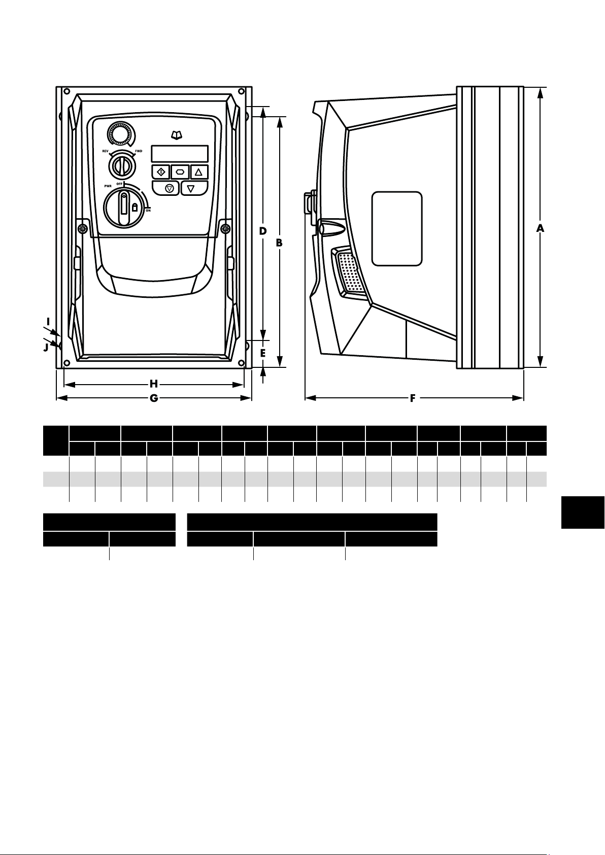
3.5. Mechanical Dimensions – IP66 (Nema 4X) Enclosed Units
0
Mechanical Installation
Drive
Size
1
2 257.0 10 .12 220.0 8.67 200.0 7.8 7 28.5 1 .12 18 7. 0 7.36 188.0 7.40 176.0 6.93 4.2 0 .17 8.5 0.33 4.1 9.0
3 310.0 12.20 276.5 10.89 251.5 9.90 33.4 1 . 31 252 9.92 211 . 0 8.30 19 7.5 7. 78 4.2 0 .17 8.5 0.33 7. 6 16 .7
Frame Size Frame Size Control Terminals Power Terminals
All Frame Sizes 4 x M4 (#8) All Frame Sizes 0.5 Nm (4.5 lb-in) 1 Nm (9 lb-in)
A B D E F G H I J
mm in mm in mm in mm in mm in mm in mm in mm in mm in kg Ib
232.0 9.13 207.0 8 .15 189.0 7.44 25.0 0.98 179. 0 7.05 161 .0 6.34 148.5 5.85 4.0 0.16 8.0 0.31 3 .1 6.8
Mounting Bolts Tightening Torques
Weight
3
Version 2.00 | Optidrive ODE-3 User Guide | 11www.invertekdrives.com
Page 12
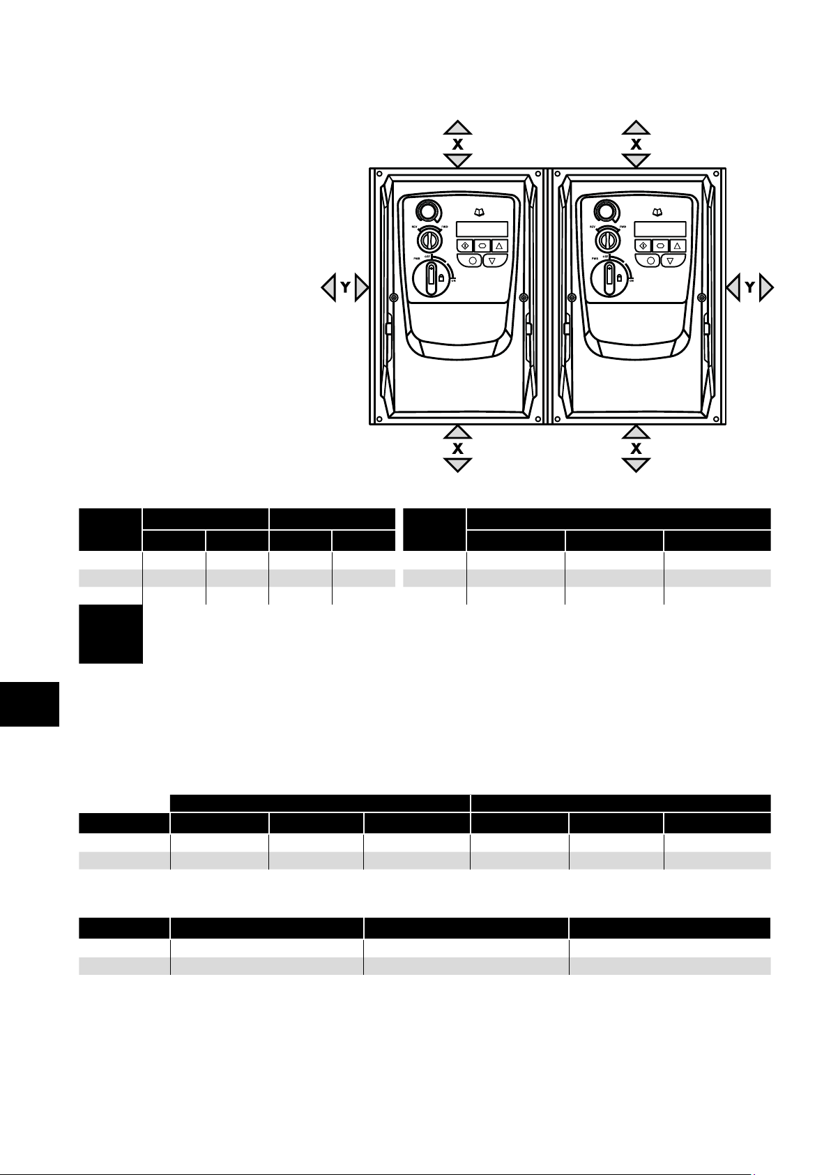
3.6. Guidelines for mounting (IP66 Units)
Before mounting the drive, ensure that the
chosen location meets the environmental
condition requirements for the drive shown
in section 9.1. Environmental.
The drive must be mounted vertically,
on a suitable flat surface.
The minimum mounting clearances
as shown in the table below must be
observed.
The mounting site and chosen mountings
should be sufficient to support the weight
of the drives.
Using the drive as a template, or the
dimensions shown above, mark the
locations required for drilling.
Suitable cable glands to maintain the
ingress protection of the drive are required.
Mechanical Installation
Gland holes for power and motor cables
are pre-moulded into the drive enclosure,
recommended gland sizes are shown
above. Gland holes for control cables
may be cut as required.
Drive
Size
1 200 7. 87 10 0.39 1 M20 (PG13.5) M20 (PG13.5) M20 (PG13.5)
2 200 7. 87 10 0.39 2 M25 (PG21) M25 (PG21) M20 (PG13.5)
3 200 7. 87 10 0.39 3 M25 (PG21) M25 (PG21) M20 (PG13.5)
X Above & Below Y Either Side
mm in mm in Power Cable Motor Cable Control Cables
Typical drive heat losses are approximately 3% of operating load conditions.
NOTE
Above are guidelines only and the operating ambient temperature of the drive MUST be
maintained at all times.
0 0
Drive
Size
Cable Gland Sizes
3
3.7. Gland Plate and Lock Off
The use of a suitable gland system is required to maintain the appropriate IP / Nema rating. The gland plate has pre moulded cable
entry holes for power and motor connections suitable for use with glands as shown in the following table. Where additional holes are
required, these can be drilled to suitable size. Please take care when drilling to avoid leaving any particles within the product.
Cable Gland recommended Hole Sizes & types:
Power & Motor Cables Control & Signal Cables
Drive Size Power Cable Motor Cable Control Cables Power Cable Motor Cable Control Cables
Size 1 22mm PG13.5 M20 22mm PG13.5 M20
Size 2 & 3 27mm PG21 M25 22mm PG13.5 M20
Flexible Conduit Hole Sizes:
Drive Size Drill Size Trade Size Metric
Size 1 28mm ¾ in 21
Size 2 & 3 35mm 1 in 27
UL rated ingress protection ("Type" ) is only met when cables are installed using a UL recognized bushing or fitting for a flexible-
conduit system which meets the required level of protection ("Type").
For conduit installations the conduit entry holes require standard opening to the required sizes specified per the NEC.
Not intended for installation using rigid conduit system.
12 | Optidrive ODE-3 User Guide | Version 2.00 www.invertekdrives.com
Page 13
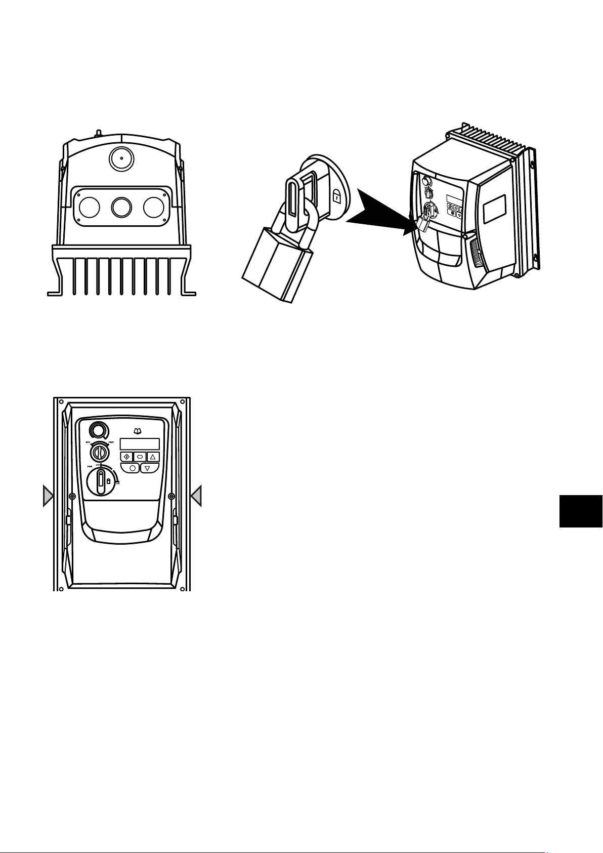
Power Isolator Lock Off
On the switched models the main power isolator switch can be locked in the ‘Off’ position using a 20mm standard shackle padlock
(not supplied).
IP66 / Nema 4X Gland Plate IP66 / Nema 4X Unit Lock Off
3.8. Removing the Terminal Cover
To access the connection terminals, the drive front cover needs to be removed as shown.
Mechanical Installation
IP66 / Nema 4X Units
Removing the 2 screws on the front of the product allows access to the connection terminals, as shown below.
0
3.9. Routine Maintenance
The drive should be included within the scheduled maintenance program so that the installation maintains a suitable operating
environment, this should include:
Ambient temperature is at or below that set out in section 9.1. Environmental.
Heat sink fans freely rotating and dust free.
The Enclosure in which the drive is installed should be free from dust and condensation; furthermore ventilation fans and air filters
should be checked for correct air flow.
Checks should also be made on all electrical connections, ensuring screw terminals are correctly torqued; and that power cables
have no signs of heat damage.
3
Version 2.00 | Optidrive ODE-3 User Guide | 13www.invertekdrives.com
Page 14
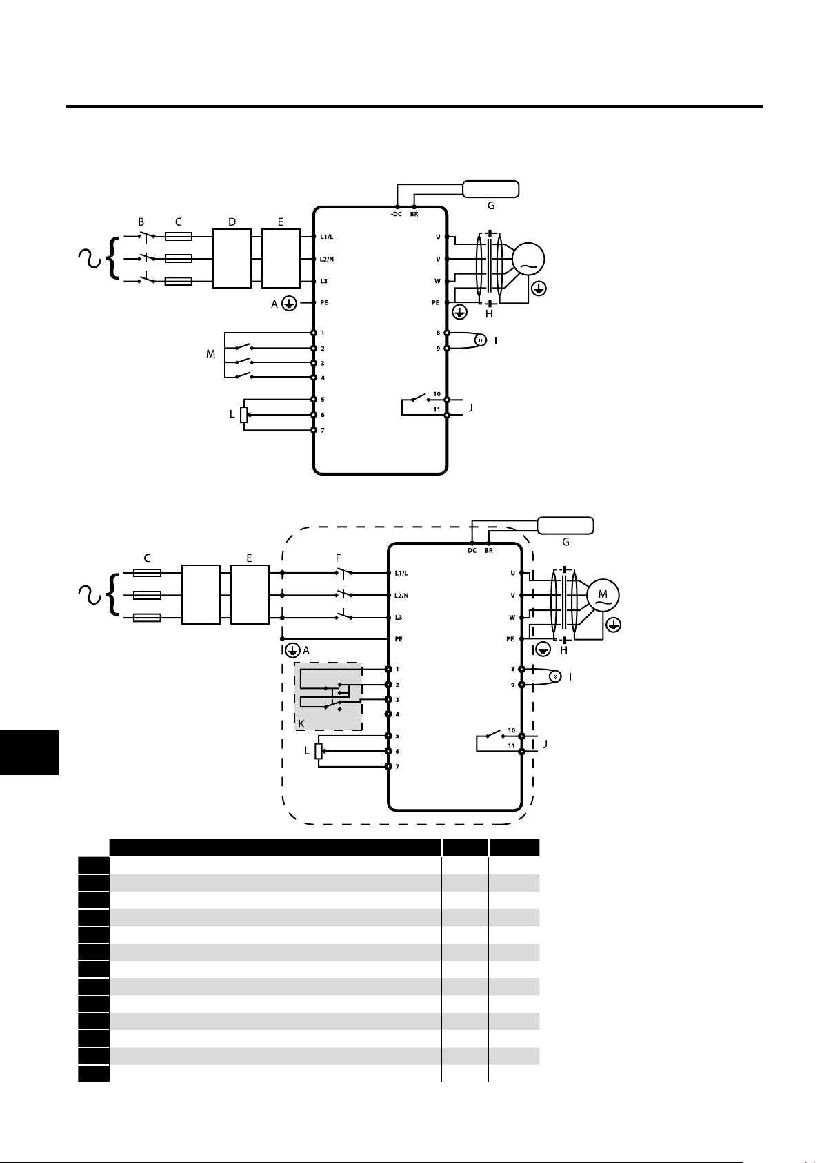
4. Power & Control Wiring
4.1. Connection Diagram
4.1.1. IP20 & IP66 (Nema 4X) Non-Switched Units
Power & Control Wiring
M
4
4.1.2. IP66 (Nema 4X) Switched Units
D
Key Sec. Page
A Protective Earth (PE) Connection 4.2 11
B Incoming Power Connection 4.3 12
C Fuse / Circuit Breaker Selection 4.3.2 12
D Optional Input Choke 4.3.3 12
E Optional External EMC Filter 4 .10 14
F Internal Disconnect / Isolator 4.3 12
G Optional Brake Resistor 4 .11 14
H Motor Connection
I Analog Output 4.8.1 14
J Relay Output 4.8.2 14
K Using the REV/0/FWD Selector Switch (Switched Version Only) 4.7 13
L Analog Inputs 4.8.3 14
M Digital Inputs 4.8.4 14
14 | Optidrive ODE-3 User Guide | Version 2.00 www.invertekdrives.com
Page 15

4.2. Protective Earth (PE) Connection
Grounding Guidelines
The ground terminal of each Optidrive should be individually connected DIRECTLY to the site ground bus bar (through the filter if
installed). Optidrive ground connections should not loop from one drive to another, or to, or from any other equipment. Ground loop
impedance must confirm to local industrial safety regulations. To meet UL regulations, UL approved ring crimp terminals should be
used for all ground wiring connections.
The drive Safety Ground must be connected to system ground. Ground impedance must conform to the requirements of national and
local industrial safety regulations and/or electrical codes. The integrity of all ground connections should be checked periodically.
Protective Earth Conductor
The Cross sectional area of the PE Conductor must be at least equal to that of the incoming supply conductor.
Safety Ground
This is the safety ground for the drive that is required by code. One of these points must be connected to adjacent building steel
(girder, joist), a floor ground rod, or bus bar. Grounding points must comply with national and local industrial safety regulations and/
or electrical codes.
Motor Ground
The motor ground must be connected to one of the ground terminals on the drive.
Ground Fault Monitoring
As with all inverters, a leakage current to earth can exist. The Optidrive is designed to produce the minimum possible leakage current
whilst complying with worldwide standards. The level of current is affected by motor cable length and type, the effective switching
frequency, the earth connections used and the type of RFI filter installed. If an ELCB (Earth Leakage Circuit Breaker) is to be used, the
following conditions apply:
A Type B Device must be used.
The device must be suitable for protecting equipment with a DC component in the leakage current.
Individual ELCBs should be used for each Optidrive.
Power & Control Wiring
Shield Termination (Cable Screen)
The safety ground terminal provides a grounding point for the motor cable shield. The motor cable shield connected to this terminal
(drive end) should also be connected to the motor frame (motor end). Use a shield terminating or EMI clamp to connect the shield to
the safety ground terminal.
4.3. Incoming Power Connection
4.3.1. Cable Selection
For 1 phase supply, the mains power cables should be connected to L1/L, L2/N.
For 3 phase supplies, the mains power cables should be connected to L1, L2, and L3. Phase sequence is not important.
For compliance with CE and C Tick EMC requirements, refer to section 4.10 EMC Compliant Installation on page 14.
A fixed installation is required according to IEC61800-5-1 with a suitable disconnecting device installed between the Optidrive
and the AC Power Source. The disconnecting device must conform to the local safety code / regulations (e.g. within Europe,
EN60204-1, Safety of machinery).
The cables should be dimensioned according to any local codes or regulations. Maximum dimensions are given in section 9.2.
Rating Tables.
4.3.2. Fuse / Circuit Breaker Selection
Suitable fuses to provide wiring protection of the input power cable should be installed in the incoming supply line, according to
the data in section 9.2. Rating Tables. The fuses must comply with any local codes or regulations in place. In general, type gG (IEC
60269) or UL type J fuses are suitable; however in some cases type aR fuses may be required. The operating time of the fuses must
be below 0.5 seconds.
Where allowed by local regulations, suitably dimensioned type B MCB circuit breakers of equivalent rating may be utilised in
place of fuses, providing that the clearing capacity is sufficient for the installation.
The maximum permissible short circuit current at the Optidrive Power terminals as defined in IEC60439-1 is 100kA.
4
Version 2.00 | Optidrive ODE-3 User Guide | 15www.invertekdrives.com
Page 16
4.3.3. Optional Input Choke
An optional Input Choke is recommended to be installed in the supply line for drives where any of the following conditions occur:
o The incoming supply impedance is low or the fault level / short circuit current is high.
o The supply is prone to dips or brown outs.
o An imbalance exists on the supply (3 phase drives).
o The power supply to the drive is via a busbar and brush gear system (typically overhead Cranes).
In all other installations, an input choke is recommended to ensure protection of the drive against power supply faults. Part numbers
are shown in the table.
4.4. Motor Connection
The drive inherently produces fast switching of the output voltage (PWM) to the motor compared to the mains supply, for motors
which have been wound for operation with a variable speed drive then there is no preventative measures required, however if the
Power & Control Wiring
quality of insulation is unknown then the motor manufacturer should be consulted and preventative measures may be required.
The motor should be connected to the Optidrive U, V, and W terminals using a suitable 3 or 4 core cable. Where a 3 core cable
is utilised, with the shield operating as an earth conductor, the shield must have a cross sectional area at least equal to the phase
conductors when they are made from the same material. Where a 4 core cable is utilised, the earth conductor must be of at least
equal cross sectional area and manufactured from the same material as the phase conductors.
The motor earth must be connected to one of the Optidrive earth terminals.
Maximum permitted motor cable length for all models: 100 metres shielded, 150 metres unshielded.
Where multiple motors are connected to a single drive using parallel cables, an output choke must be installed.
Supply Frame Size AC Input Inductor
230 Volt
1 Phase
400 Volt
3 Phase
1 OPT-2-L1016-20
2 OPT-2-L1025-20
3 N/A
2 OPT-2-L3006-20
2 OPT-2-L3010-20
3 OPT-2-L3036-20
4 OPT-2-L3050-20
4
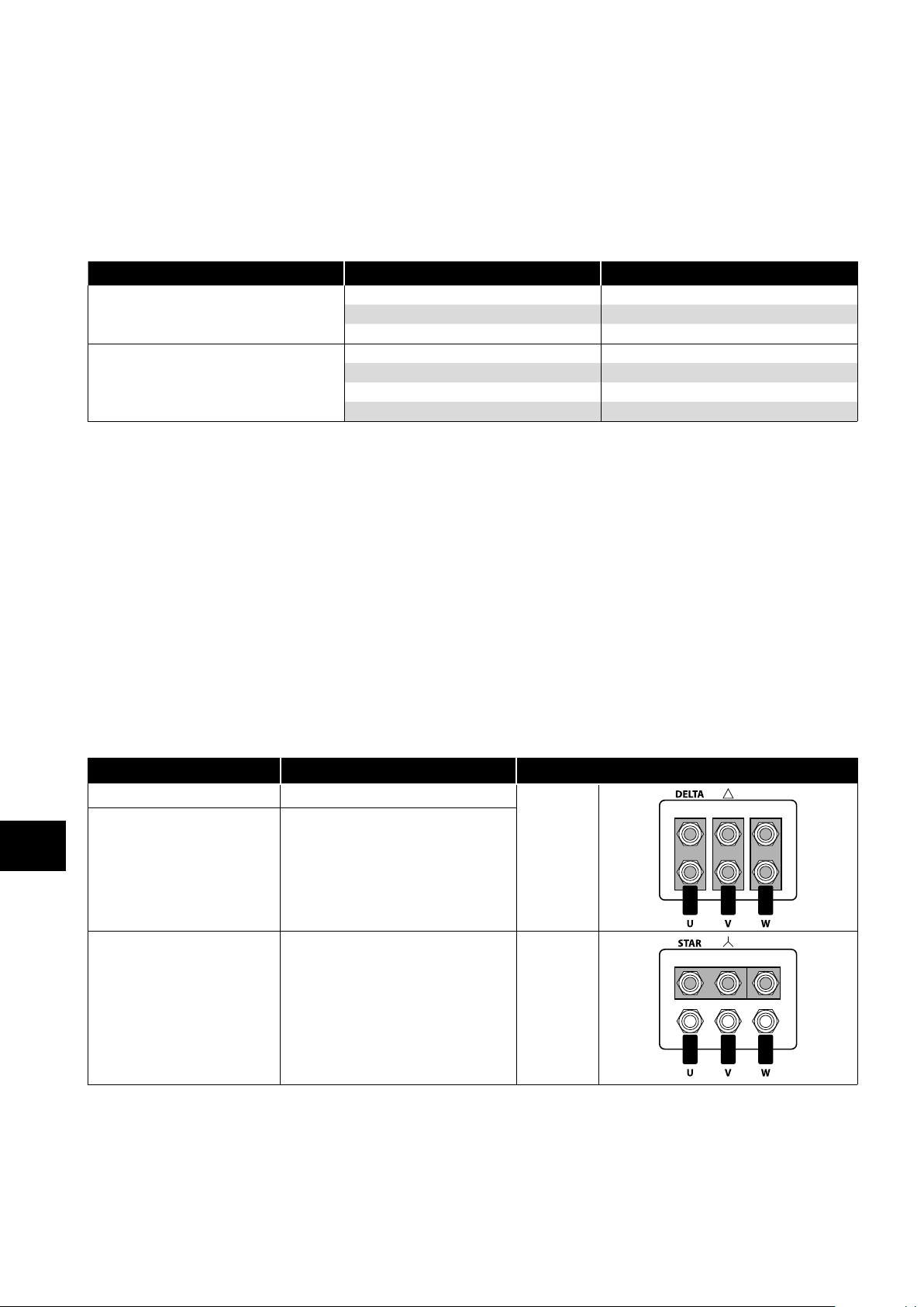
4.5. Motor Terminal Box Connections
Most general purpose motors are wound for operation on dual voltage supplies. This is indicated on the nameplate of the motor. This
operational voltage is normally selected when installing the motor by selecting either STAR or DELTA connection. STAR always gives
the higher of the two voltage ratings.
Incoming Supply Voltage Motor Nameplate Voltages Connection
230 230 / 400
400 400 / 690
400 230 / 400 Star
Delta
4.6. Control Terminal Wiring
All analog signal cables should be suitably shielded. Twisted pair cables are recommended.
Power and Control Signal cables should be routed separately where possible, and must not be routed parallel to each other.
Signal levels of different voltages e.g. 24 Volt DC and 110 Volt AC, should not be routed in the same cable.
Maximum control terminal tightening torque is 0.5Nm.
Control Cable entry conductor size: 0.05 – 2.5mm2 / 30 – 12 AWG.
16 | Optidrive ODE-3 User Guide | Version 2.00 www.invertekdrives.com
Page 17
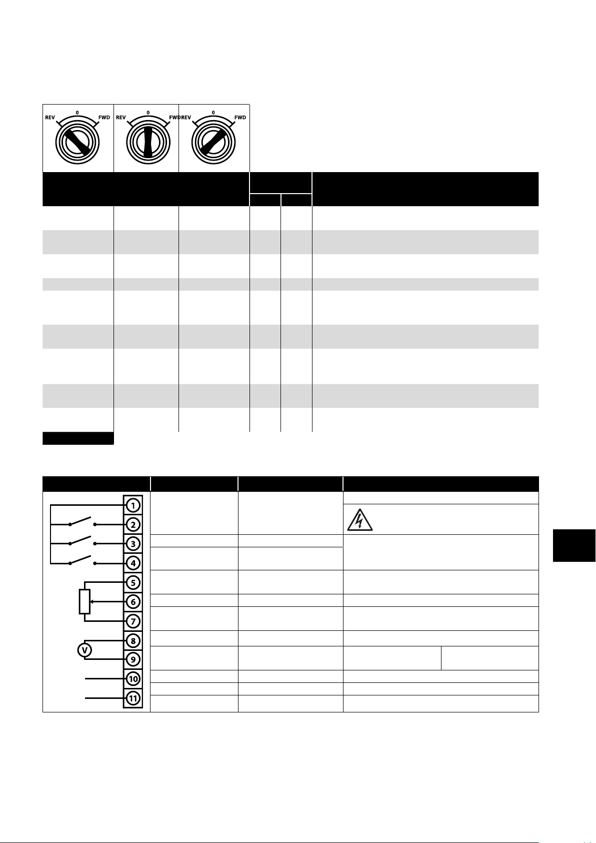
4.7. Using the REV/0/FWD Selector Switch (Switched Version Only)
By adjusting the parameter settings the Optidrive can be configured for multiple applications and not just for Forward or Reverse.
This could typically be for Hand/Off/Auto applications (also known and Local/Remote) for HVAC and pumping industries.
Parameters
Switch Position
Run Reverse STOP Run Forward 0 0
STOP STOP Run Forward 0 5,7
Preset Speed 1 STOP Run Forward 0 1
Run Reverse STOP Run Forward 0 6, 8 Run Forward or Reverse with speed controlled from the Local POT
Run in Auto STOP Run in Hand 0 4
Run in Speed
Control
Run in Preset
Speed Control
Run in Hand STOP Run in Auto 3 6
Run in Hand STOP Run in Auto 3 3
NOTE To be able to adjust parameter P-15, extended menu access must be set in P-14 (default value is 101)
STOP Run in PI Control 5 1
STOP Run in PI Control 5
to Set
P-12 P-15
0, 2,
4,5,
8..12
Notes
Factory Default Configuration
Run Forward or Reverse with speed controlled from the Local POT
Run forward with speed controlled form the local POT
Run Reverse - disabled
Run Forward with speed controlled from the Local POT
Preset Speed 1 provides a ‘Jog’ Speed set in P-20
Run in Hand – Speed controlled from the Local POT
Run in Auto 0 Speed controlled using Analog input 2 e.g. from
PLC with 4-20mA signal.
In Speed Control the speed is controlled from the Local POT
In PI Control, Local POT controls PI set point
In Preset Speed Control, P-20 sets the Preset Speed
In PI Control, POT can control the PI set point
(P-44=1)
Hand – speed controlled from the Local POT
Auto – Speed Reference from Modbus
Hand – Speed reference from Preset Speed 1 (P-20)
Auto – Speed Reference from Modbus
Power & Control Wiring
4.8. Control Terminal Connections
Default Connections Control Terminal Signal Description
+24Vdc user output, 100mA.
1 +24Vdc User Output
2 Digital Input 1 Positive logic
3 Digital Input 2
4
5 +10V User Output +10V, 10mA, 1kΩ minimum
6
7 0V 0 Volt Common, internally connected to terminal 9
8
9 0V 0 Volt Common, internally connected to terminal 7
10 Relay Common
11 Relay NO Contact Contact 250Vac, 6A / 30Vdc, 5A
Digital Input 3 /Analog
Input 2
Analog Input 1 /
Digital Input 4
Analog Output /
Digital Output
“Logic 1” input voltage range: 8V … 30V DC
“Logic 0” input voltage range: 0V … 4V DC
Digital: 8 to 30V
Analog: 0 to 10V, 0 to 20mA or 4 to 20mA
Analog: 0 to 10V, 0 to 20mA or 4 to 20mA
Digital: 8 to 30V
Analog: 0 to 10V,
Digital: 0 to 24V
Do not connect an external voltage source to
this terminal.
4
20mA maximum
Version 2.00 | Optidrive ODE-3 User Guide | 17www.invertekdrives.com
Page 18
4.8.1. Analog Output
The analog output function may be configured using parameter P-25, which is described in section 6.2. Extended Parameters on
page 24.
The output has two operating modes, dependent on the parameter selection:
Analog Mode
o The output is a 0 – 10 volt DC signal, 20mA max load current.
Digital Mode
o The output is 24 volt DC, 20mA max load current.
4.8.2. Relay Output
The relay output function may be configured using parameter P-18, which is described in section 6.2. Extended Parameters on page 24.
4.8.3. Analog Inputs
Two analog inputs are available, which may also be used as Digital Inputs if required. The signal formats are selected by parameters
as follows:
Analog Input 1 Format Selection Parameter P-16.
Analog Input 2 Format Selection Parameter P-47.
These parameters are described more fully in section 6.2. Extended Parameters on page 24.
The function of the analog input, e.g. for speed reference or PID feedback for example is defined by parameters P-15. The function of
these parameters and available options is described in section 7. Analog and Digital Input Macro Configurations on page 31.
Power & Control Wiring
4.8.4. Digital Inputs
Up to four digital inputs are available. The function of the inputs is defined by parameters P-12 and P-15, which are explained in
section 7. Analog and Digital Input Macro Configurations on page 31.
4
4.9. Motor Thermal Overload Protection
4.9.1. Internal Thermal Overload Protection
The drive has an in-built motor thermal overload function; this is in the form of an “I.t-trP” trip after delivering >100% of the value set in
P-08 for a sustained period of time (e.g. 150% for 60 seconds).
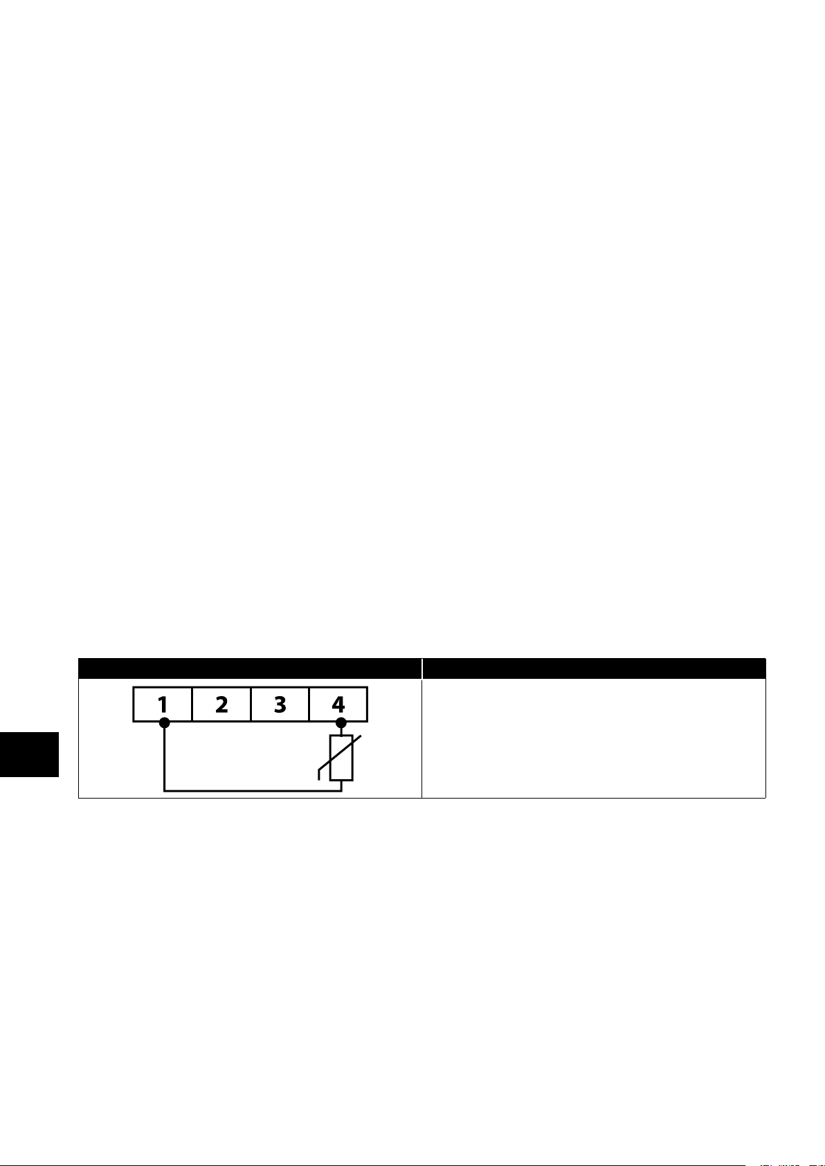
4.9.2. Motor Thermistor Connection
Where a motor thermistor is to be used, it should be connected as follows:
Control Terminal Strip Additional Information
Compatible Thermistor: PTC Type, 2.5kΩ trip level.
Use a setting of P-15 that has Input 3 function as External Trip,
e.g. P-15 = 3. Refer to section 7. Analog and Digital Input Macro
Configurations on page 31 for further details.
Set P-47 = “"
18 | Optidrive ODE-3 User Guide | Version 2.00 www.invertekdrives.com
Page 19
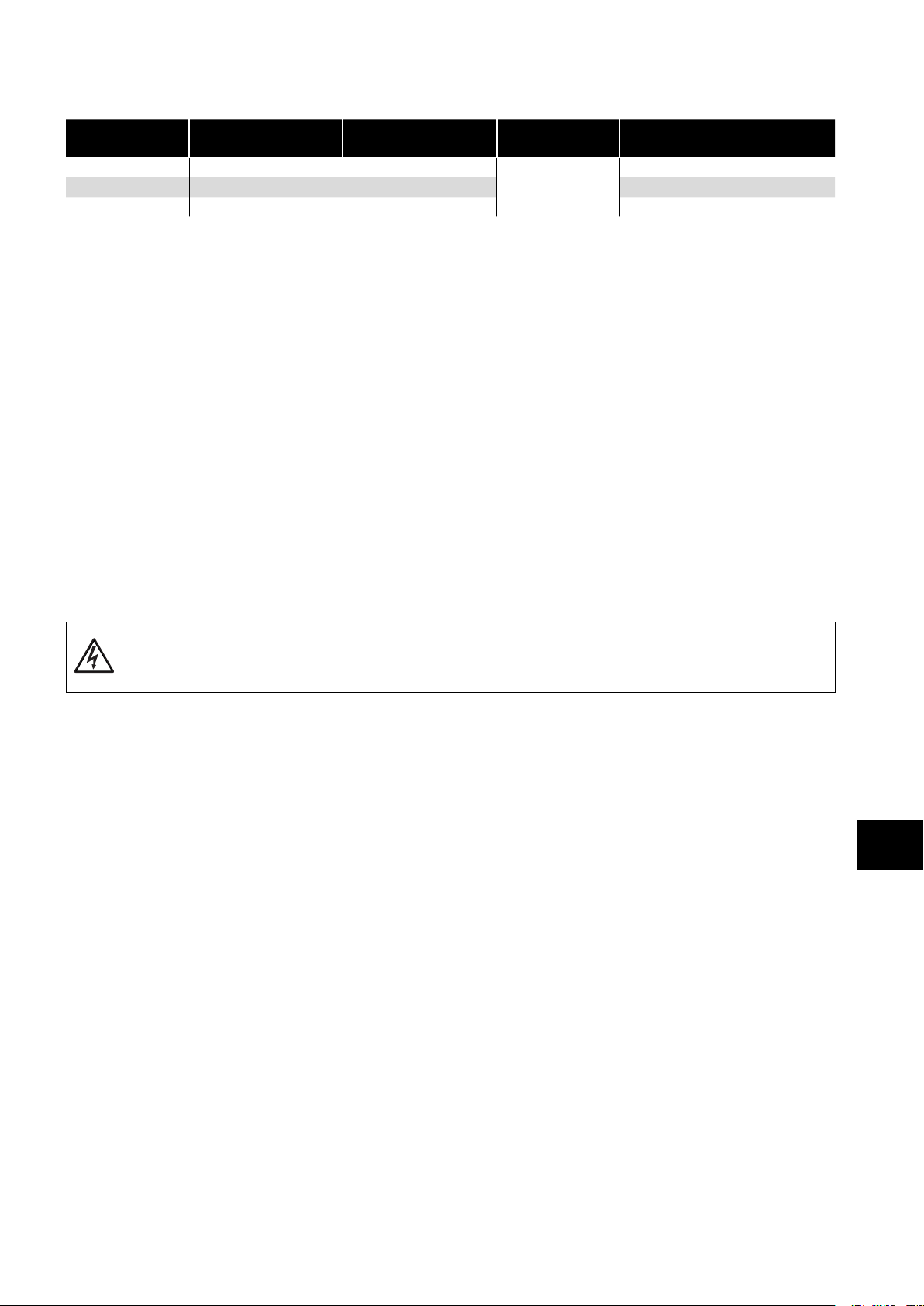
4.10. EMC Compliant Installation
Category Supply Cable Type Motor Cable Type Control Cables
6
C1
C2 Shielded
C3 Unshielded
1
A screened (shielded) cable suitable for fixed installation with the relevant mains voltage in use. Braided or twisted type screened
Shielded
1
2
3
Shielded
Shielded
Shielded
1,5
1, 5
2
Shielded
4
Maximum Permissible
Motor Cable Length
1M / 5M
5M / 25M
25M / 100M
7
7
7
cable where the screen covers at least 85% of the cable surface area, designed with low impedance to HF signals. Installation of
a standard cable within a suitable steel or copper tube is also acceptable.
2
A cable suitable for fixed installation with relevant mains voltage with a concentric protection wire. Installation of a standard cable
within a suitable steel or copper tube is also acceptable.
3
A cable suitable for fixed installation with relevant mains voltage. A shielded type cable is not necessary.
4
A shielded cable with low impedance shield. Twisted pair cable is recommended for analog signals.
5
The cable screen should be terminated at the motor end using an EMC type gland allowing connection to the motor body
through the largest possible surface area. Where drives are mounted in a steel control panel enclosure, the cable screen may be
terminated directly to the control panel using a suitable EMC clamp or gland, as close to the drive as possible. For IP66 drives,
connect the motor cable screen to the internal ground clamp.
6
Compliance with category C1 conducted emissions only is achieved. For compliance with category C1 radiated emissions,
additional measures may be required, contact your Sales Partner for further assistance.
7
Permissible cable length with additional external EMC filter.
4.11. Optional Brake Resistor
Optidrive E3 Frame Size 2 and above units have a built in Brake Transistor. This allows an external resistor to be connected to the
drive to provide improved braking torque in applications that require this.
The brake resistor should be connected to the “+” and “BR” terminals as shown.
Power & Control Wiring
The voltage level at these terminals may exceed 800VDC.
Stored charge may be present after disconnecting the mains power.
Allow a minimum of 10 minutes discharge after power off before attempting any connection to these terminals.
Suitable resistors and guidance on selection can be obtained from your Invertek Sales Partner.
4
Version 2.00 | Optidrive ODE-3 User Guide | 19www.invertekdrives.com
Page 20
5. Operation
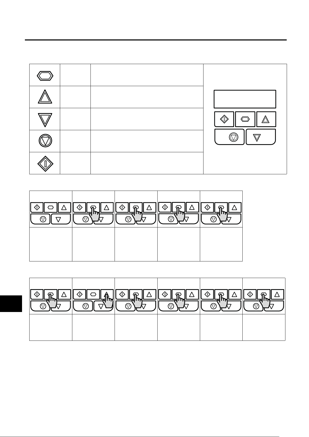
5.1. Managing the Keypad
The drive is configured and its operation monitored via the keypad and display.
NAVIGATE
UP
DOWN
RESET /
STOP
START
Used to display real-time information, to access and exit
parameter edit mode and to store parameter changes.
Used to increase speed in real-time mode or to increase
parameter values in parameter edit mode.
Used to decrease speed in real-time mode or to
decrease parameter values in parameter edit mode.
Used to reset a tripped drive.
When in Keypad mode is used to Stop a running drive.
When in keypad mode, used to Start a stopped drive or
to reverse the direction of rotation if
bi-directional keypad mode is enabled.
5.2. Operating Displays
Drive Stopped /
Disabled
Operation
5.3. Changing Parameters
5
Press and hold the
Navigate key > 2
seconds
Drive is enabled
/ running, display
shows the output
frequency (Hz)
Use the up and
down keys to
select the required
parameter
Press the Navigate
key for < 1 second.
The display will
show the motor
current (Amps)
Press the Navigate
key for < 1 second
Press the Navigate
key for < 1 second.
The display will
show the motor
power (kW)
Adjust the value
using the Up and
Down keys
If P-10 > 0, pressing
the Navigate key
for < 1 second will
display the motor
speed (RPM)
Press for < 1 second
to return to the
parameter menu
Press for > 2
seconds to return
to the operating
display
20 | Optidrive ODE-3 User Guide | Version 2.00 www.invertekdrives.com
Page 21
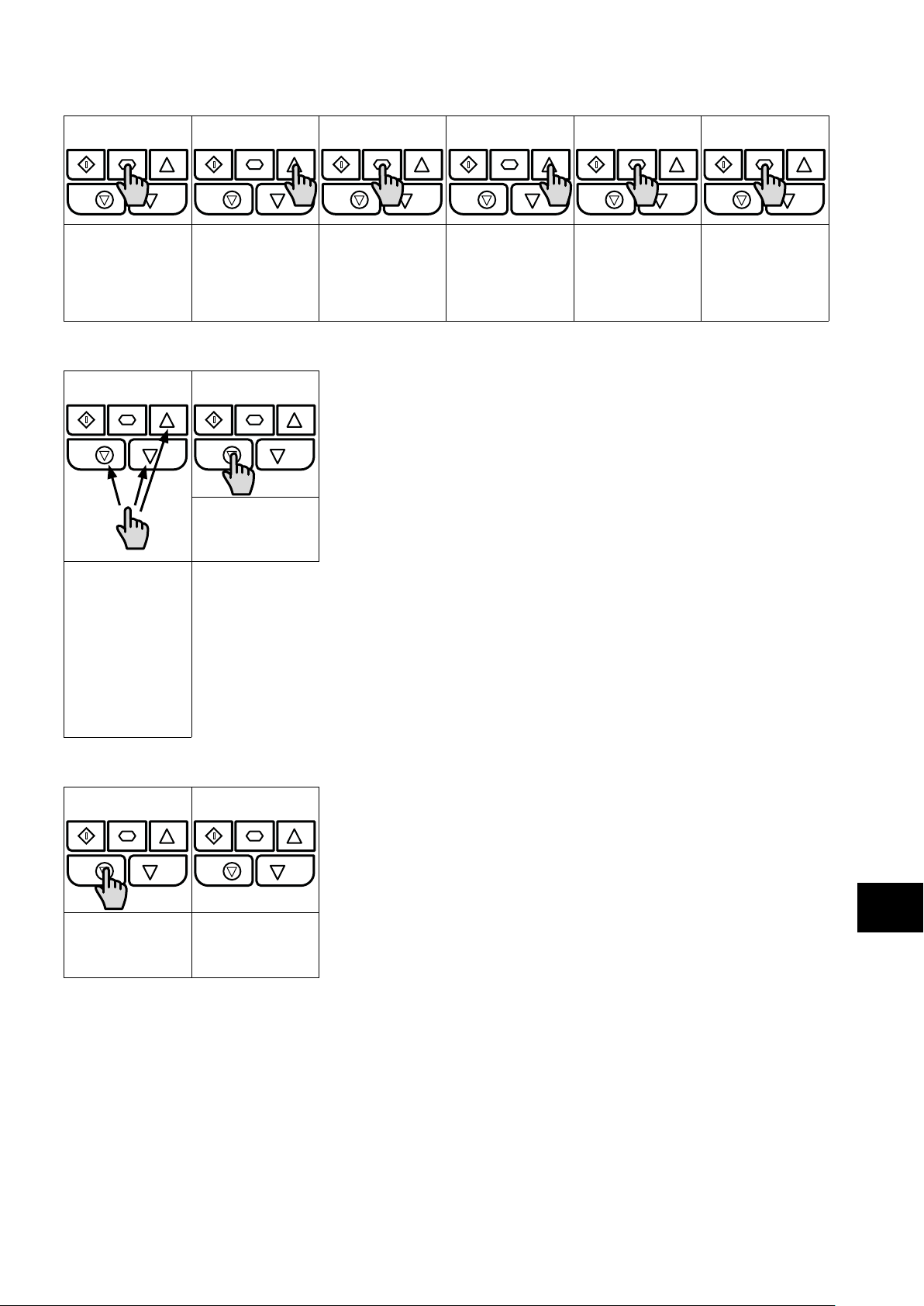
5.4. Read Only Parameter Access
Press and hold the
Navigate key > 2
seconds
Use the up and
down keys to select
P-00
5.5. Resetting Parameters
Press the Stop key.
The display will
show “”
To reset parameter
values to their
factory default
settings, press and
hold Up, Down and
Stop buttons for > 2
seconds.
The display will
show “”
Press the Navigate
key for < 1 second
Use the up and
down keys to select
the required Read
Only parameter
Press the Navigate
key for < 1 second
to display the value
Press and hold the
Navigate key > 2
seconds to return
to the operating
display
Operation
5.6. Resetting a Fault
Press the Stop key.
The display will
show “”
5
Version 2.00 | Optidrive ODE-3 User Guide | 21www.invertekdrives.com
Page 22

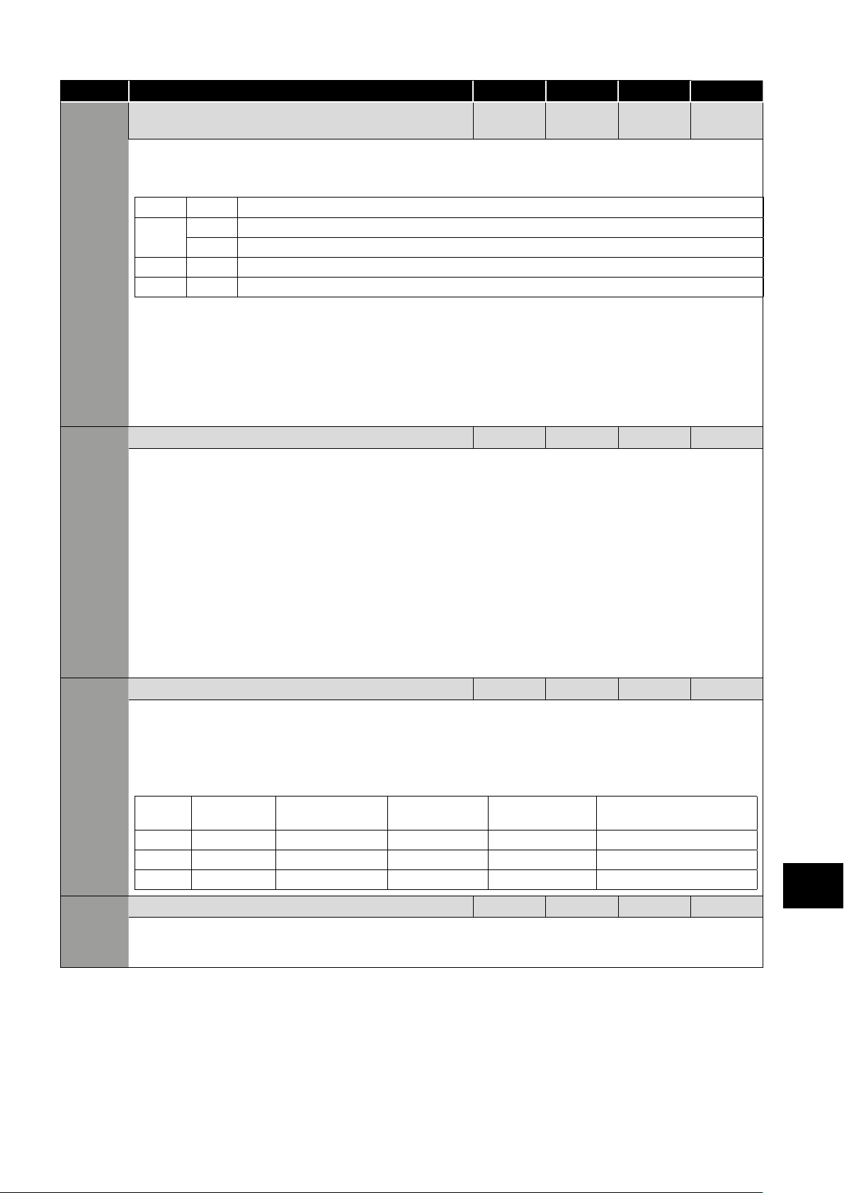
6. Parameters
6.1. Standard Parameters
Par. Description Minimum
P-01
P-02 Minimum Frequency / Speed Limit 0.0 P-01 20.0 Hz / RPM
P-03 Acceleration Ramp Time 0.00 600.0 5.0 s
P-04 Deceleration Ramp Time 0.00 600.0 5.0 s
P-05 Stopping Mode / Mains Loss Response 0 3 0 -
P-06 Energy Optimiser 0 1 0 -
Maximum Frequency / Speed Limit P-02 500.0
Maximum output frequency or motor speed limit – Hz or RPM. If P-10 >0, the value entered / displayed is in RPM.
Minimum speed limit – Hz or RPM. If P-10 >0, the value entered / displayed is in RPM.
Acceleration ramp time from zero Hz / RPM to base frequency (P-09) in seconds.
Deceleration ramp time from base frequency (P-09) to standstill in seconds. When set to 0.00, the value of P-24 is used.
Selects the stopping mode of the drive, and the behaviour in response to a loss of mains power supply during operation.
Setting On Disable On Mains Loss
0 Ramp to Stop (P-04)
1 Coast Coast
2 Ramp to Stop (P-04) Fast Ramp to Stop (P-24), Coast if P-24 = 0
3
4
Motor Energy Optimisation is intended for use in applications where the motor operates for extended time periods at constant speed
with light load. It should not be used in applications with large, sudden step changes in load or for PI control applications.
Optidrive Energy Optimisation reduces the drive internal heat losses increasing efficiency however it may result in some vibration in the
motor during light load operation. In general, this function is suited to Fan, Pump and Compressor applications.
Ramp to Stop (P-04) with AC Flux Braking
Ramp to Stop (P-04)
Ride Through (Recover energy from load to maintain operation)
Fast Ramp to Stop (P-24), Coast if P-24 = 0
No action
Maximum
Default Units
50.0
(60.0)
Hz / RPM
Parameters
P-07 Motor Rated Voltage / Back EMF at rated speed (PM /
P-08 Motor Rated Current Drive Rating Dependent A
P-09 Motor Rated Frequency 10 500 50 (60) Hz
6
P-10 Motor Rated Speed 0 30000 0 RPM
Setting Motor Energy Optimisation Optidrive Energy Optimisation
0 Disabled
1 Enabled Disabled
2 Disabled Enabled
3
BLDC)
For Induction Motors, this parameter should be set to the rated (nameplate) voltage of the motor (Volts).
For Permanent Magnet or Brushless DC Motors, it should be set to the Back EMF at rated speed.
This parameter should be set to the rated (nameplate) current of the motor.
This parameter should be set to the rated (nameplate) frequency of the motor.
This parameter can optionally be set to the rated (nameplate) RPM of the motor. When set to the default value of zero, all
speed related parameters are displayed in Hz and the slip compensation (where motor speed is maintained at a constant value
regardless of applied load) for the motor is disabled. Entering the value from the motor nameplate enables the slip compensation
function, and the Optidrive display will now show motor speed in RPM. All speed related parameters, such as Minimum and
Maximum Speed, Preset Speeds etc. will also be displayed in RPM.
NOTE If P-09 value is changed, P-10 value is reset to 0.
Enabled
Disabled
Enabled
0 250 / 500 230 / 400 V
22 | Optidrive ODE-3 User Guide | Version 2.00 www.invertekdrives.com
Page 23
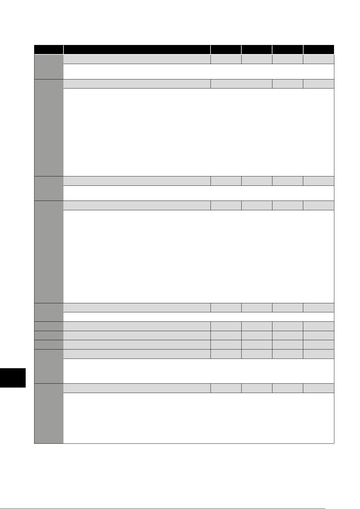
Par. Description Minimum
P-11
P-12 Primary Command Source 0 9 0 -
P-13 Operating Mode Select 0 2 0 -
Low Frequency Torque Boost 0.0
Low frequency torque can be improved by increasing this parameter. Excessive boost levels may however result in high motor current
and increased risk of tripping on Over Current or Motor Overload (refer to section 10.1. Fault Code Messages).
This parameter operates in conjunction with P-51 (Motor Control Mode) as follows:
P-51 P-11
0 0
1 All
2, 3, 4
For IM motors, when P-51 = 0 or 1, a suitable setting can usually be found by operating the motor under very low or no load
conditions at approximately 5Hz, and adjusting P-11 until the motor current is approximately the magnetising current (if known) or in
the range shown below.
Frame Size 1: 60 – 80% of motor rated current.
Frame Size 2: 50 – 60% of motor rated current.
Frame Size 3: 40 – 50% of motor rated current.
Frame Size 4: 35 – 45% of motor rated current.
0: Terminal Control. The drive responds directly to signals applied to the control terminals.
1: Uni-directional Keypad Control. The drive can be controlled in the forward direction only using the internal keypad, or
an external remote Keypad.
2: Bi-directional Keypad Control. The drive can be controlled in the forward and reverse directions u using the internal keypad,
or an external remote Keypad. Pressing the keypad START button toggles between forward and reverse.
3: Modbus Network Control. Control via Modbus RTU (RS485) using the internal Accel / Decel ramps.
4: Modbus Network Control. Control via Modbus RTU (RS485) interface with Accel / Decel ramps updated via Modbus.
5: PI Control. User PI control with external feedback signal.
6: PI Analog Summation Control. PI control with external feedback signal and summation with analog input 1.
7: CAN Control. Control via CAN (RS485) using the internal Accel / Decel ramps.
8: CAN Control. Control via CAN (RS485) interface with Accel / Decel ramps updated via CAN.
9: Slave Mode. Control via a connected Invertek drive in Master Mode. Slave drive address must be > 1.
NOTE When P-12 = 1, 2, 3, 4, 7, 8 or 9, an enable signal must still be provided at the control terminals, digital input 1.
Provides a quick set up to configure key parameters according to the intended application of the drive. Parameters are preset according
to the table.
0: Industrial Mode. Intended for general purpose applications.
1: Pump Mode. Intended for centrifugal pump applications.
2: Fan Mode. Intended for Fan applications.
Boost is automatically calculated according to autotune data.
>0
Voltage boost = P-11 x P-07.This voltage is applied at 0.0Hz, and linearly reduced until P-09 / 2.
Voltage boost = P-11 x P-07.This voltage is applied at 0.0Hz, and linearly reduced until P-09 / 2.
All
Boost current level = 4*P-11*P-08.
Maximum
Drive
Dependent
Default Units
Drive
Dependent
%
Parameters
Setting Application Current Limit
(P-54)
0 General 150% Constant
1 Pump 110 % Variable 0: Off 1: Current Limit Reduction
2 Fan 110 % Variable 2: On 1: Current Limit Reduction
P-14 Extended Menu Access code 0 65535 0 -
Enables access to Extended and Advanced Parameter Groups. This parameter must be set to the value programmed in P-37
(default: 101) to view and adjust Extended Parameters and value of P-37 + 100 to view and adjust Advanced Parameters. The code
may be changed by the user in P-37 if desired.
Torque
Characteristic
Spin Start (P-33) Thermal Overload Limit
Reaction (P-60 Index 2)
0: Off 0: Trip
Version 2.00 | Optidrive ODE-3 User Guide | 23www.invertekdrives.com
6
Page 24
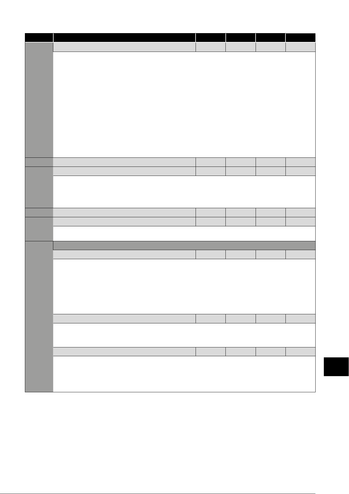
6.2. Extended Parameters
Par. Description Minimum
P-15 Digital Input Function Select 0 17 0 -
P-16 Analog Input 1 Signal Format See Below U0-10 -
P-17 Maximum Effective Switching Frequency 4 32 8 kHz
P-18 Output Relay Function Select 0 9 1 -
Parameters
P- Relay Threshold Level 0.0 200.0 100.0 %
P-20 Preset Frequency / Speed 1 -P-01 P-01 5.0 Hz / RPM
P-21 Preset Frequency / Speed 2 -P-01 P-01 25.0 Hz / RPM
P-22 Preset Frequency / Speed 3 -P-01 P-01 40.0 Hz / RPM
P-23 Preset Frequency / Speed 4 -P-01 P-01 P-09 Hz / RPM
6
P-24 2nd Ramp Time (Fast Stop) 0.00 600.0 0.00 s
Maximum
Defines the function of the digital inputs depending on the control mode setting in P-12. See section 7. Analog and Digital Input
Macro Configurations for more information.
= Uni-polar 0 to 10 Volt Signal. The drive will remain at minimum speed (P-02) if the analog reference after scaling and
offset are applied is =<0.0%. 100% signal means the output frequency / speed will be the value set in P-01.
= Uni-polar 0 to 10 Volt Signal, bi-directional operation. The drive will operate the motor in the reverse
direction of rotation if the analog reference after scaling and offset are applied is <0.0%. E.g. for bidirectional control from a 0 – 10
volt signal, set P-35 = 200.0%, P-39 = 50.0%.
= 0 to 20mA Signal.
= 4 to 20mA Signal, the Optidrive will trip and show the fault code if the signal level falls below 3mA.
= 4 to 20mA Signal, the Optidrive will run at Preset Speed 1 (P-20 if the signal level falls below 3mA.
= 20 to 4mA Signal, the Optidrive will trip and show the fault code if the signal level falls below 3mA.
= 20 to 4mA Signal, the Optidrive will run at Preset Speed 1 (P-20 if the signal level falls below 3mA.
= 10 to 0 Volt Signal (Uni-polar). The drive will operate at Maximum Frequency / Speed if the analog
reference after scaling and offset are applied is =<0.0%.
Sets maximum effective switching frequency of the drive. If “rEd” is displayed when the parameter is viewed, the switching frequency
has been reduced to the level in P00-32 due to excessive drive heatsink temperature.
Selects the function assigned to the relay output. The relay has two output terminals, Logic 1 indicates the relay is active, and
therefore terminals 10 and 11 will be connected.
0: Drive Enabled (Running). Logic 1 when the motor is enabled.
1: Drive Healthy. Logic 1 when power is applied to the drive and no fault exists.
2: At Target Frequency (Speed). Logic 1 when the output frequency matches the setpoint frequency.
3: Drive Tripped. Logic 1 when the drive is in a fault condition.
4: Output Frequency >= Limit. Logic 1 when the output frequency exceeds the adjustable limit set in P-19.
5: Output Current >= Limit. Logic 1 when the motor current exceeds the adjustable limit set in P-19.
6: Output Frequency < Limit. Logic 1 when the output frequency is below the adjustable limit set in P-19.
7: Output Current < Limit. Logic 1 when the motor current is below the adjustable limit set in P-19.
8: Analog Input 2 > Limit. Logic 1 when the signal applied to analog input 2 exceeds the adjustable limit set in P-19.
9: Drive Ready to Run. Logic 1 when the drive is ready to run, no trip present.
Adjustable threshold level used in conjunction with settings 4 to 8 of P-18.
Preset Speeds / Frequencies selected by digital inputs depending on the setting of P-15.
If P-10 = 0, the values are entered as Hz. If P-10 > 0, the values are entered as RPM.
NOTE Changing the value of P-09 will reset all values to factory default settings.
This parameter allows a 2nd ramp time to be programmed into the drive.
This ramp time is automatically selected in the case of a mains power loss if P-05 = 2 or 3. When set to 0.00, the drive will coast to
stop.
When using a setting of P-15 that provides a “Fast Stop” function, this ramp time is also used.
In addition, if P-24 > 0, P-02 > 0, P-26=0 and P-27 = P-02, this ramp time is applied to both acceleration and deceleration when
operating below minimum speed, allowing selection of an alternative ramp when operating outside of the normal speed range,
which may be useful in pump and compressor applications.
Default Units
24 | Optidrive ODE-3 User Guide | Version 2.00 www.invertekdrives.com
Page 25
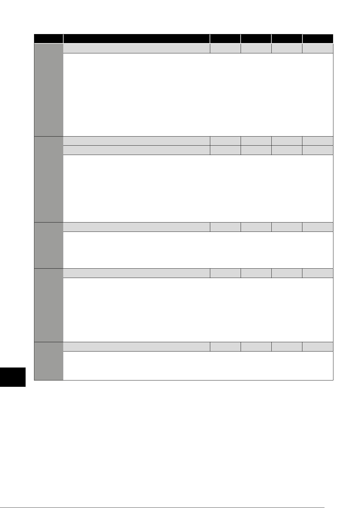
Par. Description Minimum
P-25 Analog Output Function Select 0
Digital Output Mode. Logic 1 = +24V DC
0: Drive Enabled (Running). Logic 1 when the Optidrive is enabled (Running).
1: Drive Healthy. Logic 1 When no Fault condition exists on the drive.
2: At Target Frequency (Speed). Logic 1 when the output frequency matches the setpoint frequency.
3: Drive Tripped. Logic 1 when the drive is in a fault condition.
4: Output Frequency >= Limit. Logic 1 when the output frequency exceeds the adjustable limit set in P-19.
5: Output Current >= Limit. Logic 1 when the motor current exceeds the adjustable limit set in P-19.
6: Output Frequency < Limit. Logic 1 when the output frequency is below the adjustable limit set in P-19.
7: Output Current < Limit. Logic 1 when the motor current is below the adjustable limit set in P-19.
Analog Output Mode
8: Output Frequency (Motor Speed). 0 to P-01, resolution 0.1Hz.
9: Output (Motor) Current. 0 to 200% of P-08, resolution 0.1A.
10: Output Power. 0 – 200% of drive rated power.
11: Load Current. 0 – 200% of P-08, resolution 0.1A.
P-26 Skip frequency hysteresis band 0.0 P-01 0.0 Hz / RPM
P-27 Skip Frequency Centre Point 0.0 P-01 0.0 Hz / RPM
The Skip Frequency function is used to avoid the Optidrive operating at a certain output frequency, for example at a frequency
which causes mechanical resonance in a particular machine. Parameter P-27 defines the centre point of the skip frequency band,
and is used in conjunction with P-26. The Optidrive output frequency will ramp through the defined band at the rates set in P-03 and
P-04 respectively, and will not hold any output frequency within the defined band. If the frequency reference applied to the drive is
within the band, the Optidrive output frequency will remain at the upper or lower limit of the band.
P-28 V/F Characteristic Adjustment Voltage 0 P-07 0 V
P-29 V/F Characteristic Adjustment Voltage 0.0 P-09 0.0 Hz
This parameter in conjunction with P-28 sets a frequency point at which the voltage set in P-29 is applied to the motor. Care must be
taken to avoid overheating and damaging the motor when using this feature.
P-30 Start Mode, Automatic Restart, Fire Mode Operation
Index 1: Start Mode & Automatic Restart N/A N/A Edge-r -
Selects whether the drive should start automatically if the enable input is present and latched during power on. Also configures the
Automatic Restart function.
: Following Power on or reset, the drive will not start if Digital Input 1 remains closed. The Input must be closed after a
power on or reset to start the drive.
: Following a Power On or Reset, the drive will automatically start if Digital Input 1 is closed.
To : Following a trip, the drive will make up to 5 attempts to restart at 20 second intervals. The
numbers of restart attempts are counted, and if the drive fails to start on the final attempt, the drive will trip with a fault, and will
require the user to manually reset the fault. The drive must be powered down to reset the counter.
Index 2: Fire Mode Input Logic 0 1 0 -
Defines the operating logic when a setting of P-15 is used which includes Fire Mode, e.g. settings 15, 16 & 17.
0: Normally Closed (NC) Input. Fire Mode active if input is open.
1: Normally Open (NO) Input. Fire Mode active if input is closed.
Index 3: Fire Mode Input Type 0 1 0 -
Defines the input type when a setting of P-15 is used which includes Fire Mode, e.g. settings 15, 16 & 17.
0: Maintained Input. The drive will remain in Fire Mode, only as long the fire mode input signal remains
(Normally Open or Normally Closed operation is supported depending on Index 2 setting).
1: Momentary Input. Fire Mode is activated by a momentary signal on the input. Normally Open or Normally Closed
operation is supported depending on Index 2 setting. The drive will remain in Fire Mode until disabled or powered off.
Maximum
11 8
Default Units
-
Parameters
6
Version 2.00 | Optidrive ODE-3 User Guide | 25www.invertekdrives.com
Page 26
Par. Description Minimum
P-31 Keypad Start Mode Select 0 7 1 -
P-32 Index 1: Duration 0.0 25.0 0.0 s
P-33 Spin Start 0 2 0 -
P-34 Brake Chopper Enable (Not Size 1) 0 4 0 -
Parameters
P-35 Analog Input 1 Scaling / Slave Speed Scaling 0.0 2000.0 100.0 %
6
Maximum
This parameter is active only when operating in Keypad Control Mode (P-12 = 1 or 2) or Modbus Mode (P-12 = 3 or 4). When
settings 0, 1, 4 or 5 are used, the Keypad Start and Stop keys are active, and control terminals 1 and 2 must be linked together. Settings
2, 3, 6 and 7 allow the drive to be started from the control terminals directly, and the keypad Start and Stop keys are ignored.
0: Minimum Speed, Keypad Start
1: Previous Speed, Keypad Start
2: Minimum Speed, Terminal Enable
3: Previous Speed, Terminal Enable
4: Current Speed, Keypad Start
5: Preset Speed 4, Keypad Start
6: Current Speed, Terminal Start
7: Preset Speed 4, Terminal Start
Index 2: DC Injection Mode 0 2 0 -
Index 1: Defines the time for which a DC current is injected into the motor. DC Injection current level may be adjusted in P-59.
Index 2: Configures the DC Injection Function as follows:
0: DC Injection on Stop. DC is injected into the motor at the current level set in P-59 following a stop command, after the output
frequency has reduced to P-58 for the time set in Index 1.
NOTE If the drive is in Standby Mode prior to disable, the DC injection is disabled
1: DC Injection on Start. DC is injected into the motor at the current level set in P-59 for the time set in Index 1 immediately after
the drive is enabled, prior to the output frequency ramping up. The output stage remains active during this phase. This can be used to
ensure the motor is at standstill prior to starting.
2: DC Injection on Start & Stop. DC injection applied as both settings 0 and 1 above.
0: Disabled
1: Enabled. When enabled, on start up the drive will attempt to determine if the motor is already rotating, and will begin to control
the motor from its current speed. A short delay may be observed when starting motors which are not turning.
2: Enabled on Trip, Brown Out or Coast Stop. Spin start is only activated following the events listed, otherwise it is
disabled.
0: Disabled
1: Enabled With Software Protection. Brake chopper enabled with software protection for a 200W continuous rated
resistor.
2: Enabled Without Software Protection. Enables the internal brake chopper without software protection. An external
thermal protection device should be fitted.
3: Enabled With Software Protection. As setting 1, however the Brake Chopper is only enabled during a change of the
frequency setpoint, and is disabled during constant speed operation.
4: Enabled Without Software Protection. As setting 2, however the Brake Chopper is only enabled during a change of the
frequency setpoint, and is disabled during constant speed operation.
Analog Input 1 Scaling. The analog input signal level is multiplied by this factor, e.g. if P-16 is set for a 0 – 10V signal, and the
scaling factor is set to 200.0%, a 5 volt input will result in the drive running at maximum frequency / speed (P-01).
Slave Speed Scaling. When operating in Slave Mode (P-12 = 9), the operating speed of the drive will be the Master speed
multiplied by this factor, limited by the minimum and maximum speeds.
Default Units
26 | Optidrive ODE-3 User Guide | Version 2.00 www.invertekdrives.com
Page 27
Par. Description Minimum
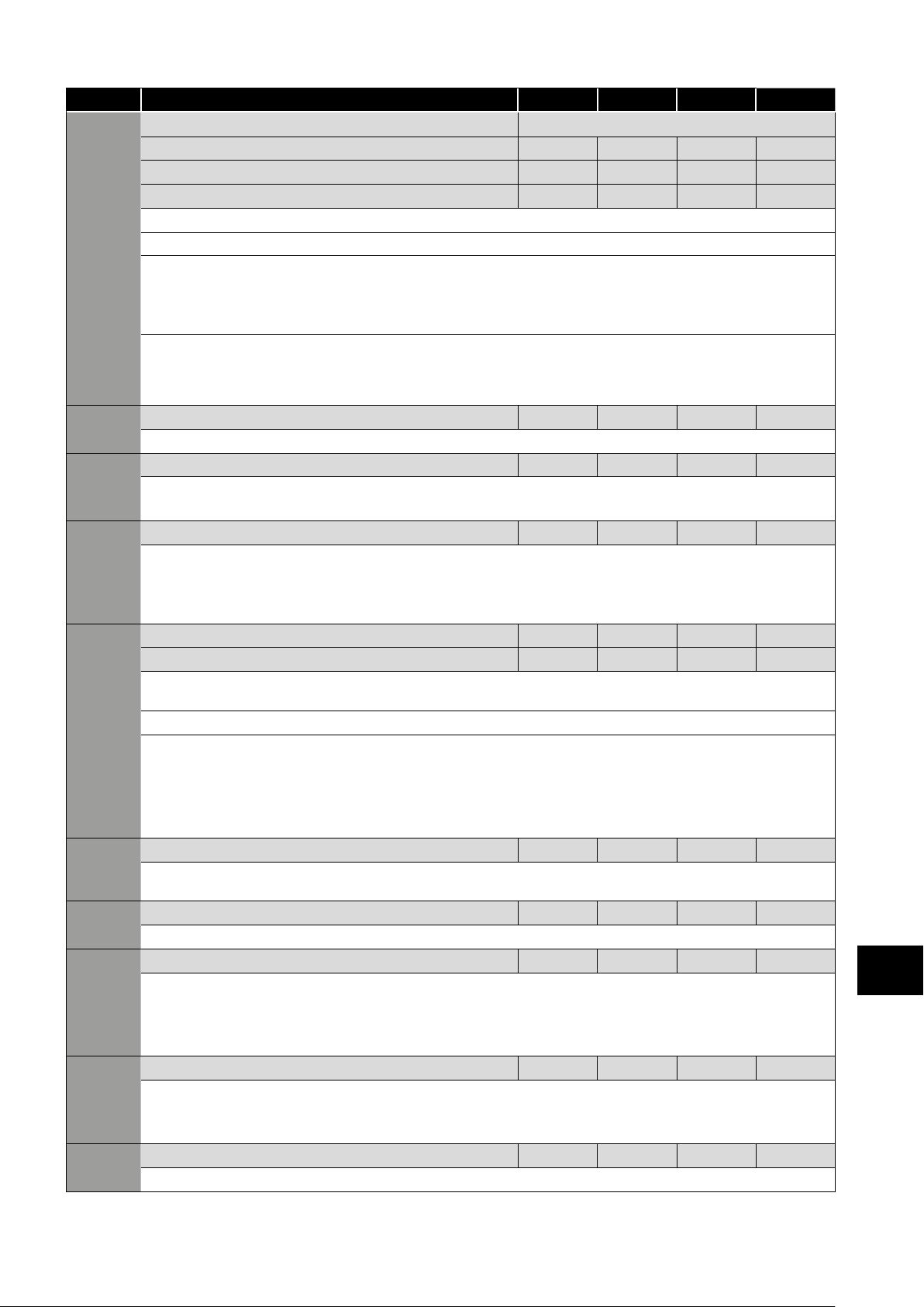
P-36 Serial Communications Configuration See Below
Index 1: Address 0 63 1 -
Index 2: Baud Rate 9.6 1000 115.2 kbps
Index 3: Communication loss protection 0 3000 t 3000 ms
This parameter has three sub settings used to configure the Modbus RTU Serial Communications. The Sub Parameters are:
1st Index: Drive Address: Range: 0 – 63, default: 1.
2nd Index: Baud Rate & Network type: Selects the baud rate and network type for the internal RS485
communication port.
For Modbus RTU: Baud rates 9.6, 19.2, 38.4, 57.6, 115.2 kbps are available.
For CAN: Baud rates 125, 250, 500 & 1000 kbps are available.
3rd Index: Watchdog Timeout: Defines the time for which the drive will operate without receiving a valid command telegram
to Register 1 (Drive Control Word) after the drive has been enabled. Setting 0 disables the Watchdog timer. Setting a value of 30,
100, 1000, or 3000 defines the time limit in milliseconds for operation. A ‘’ suffix selects trip on loss of communication. An ‘’ suffix
means that the drive will coast stop (output immediately disabled) but will not trip.
P-37 Access Code Definition 0 9999 101 -
Defines the access code which must be entered in P-14 to access parameters above P-14.
P-38 Parameter Access Lock 0 1 0 -
0: Unlocked. All parameters can be accessed and changed.
1: Locked. Parameter values can be displayed, but cannot be changed except P-38.
P-39 Analog Input 1 Offset -500.0 500.0 0.0 %
Sets an offset, as a percentage of the full scale range of the input, which is applied to the analog input signal. This parameter
operates in conjunction with P-35, and the resultant value can be displayed in P00-01.
The resultant value is defined as a percentage, according to the following:
P00-01 = (Applied Signal Level(%) - P-39) x P-35).
P-40 Index 1: Display Scaling Factor 0.000 16.000 0.000 -
Index 2: Display Scaling Source 0 3 0 -
Allows the user to program the Optidrive to display an alternative output unit scaled from either output frequency (Hz), Motor
Speed (RPM) or the signal level of PI feedback when operating in PI Mode.
Index 1: Used to set the scaling multiplier. The chosen source value is multiplied by this factor.
Index 2: Defines the scaling source as follows:
0: Motor Speed. Scaling is applied to the output frequency if P-10 = 0, or motor RPM if P-10 > 0.
1: Motor Current. Scaling is applied to the motor current value (Amps).
2: Analog Input 2 Signal Level. Scaling is applied to analog input 2 signal level, internally represented as 0 – 100.0%.
3: PI Feedback. Scaling is applied to the PI feedback selected by P-46, internally represented as 0 – 100.0%.
P-41 PI Controller Proportional Gain 0.0 30.0 1.0 -
PI Controller Proportional Gain. Higher values provide a greater change in the drive output frequency in response to small changes
in the feedback signal. Too high a value can cause instability.
P-42 PI Controller Integral Time 0.0 30.0 1.0 5
PI Controller Integral Time. Larger values provide a more damped response for systems where the overall process responds slowly.
P-43 PI Controller Operating Mode 0 1 0 -
0: Direct Operation. Use this mode if when the feedback signal drops, the motor speed should increase.
1: Inverse Operation. Use this mode if when the feedback signal drops, the motor speed should decrease.
2: Direct Operation, Wake at Full Speed. As setting 0, but on restart from Standby, PI Output is set to 100%.
3: Reverse Operation, Wake at Full Speed. As setting 0, but on restart from Standby, PI Output is set to 100%.
P-44 PI Reference (Setpoint) Source Select 0 1 0 -
Selects the source for the PID Reference / Setpoint.
0: Digital Preset Setpoint. P-45 is used.
1: Analog Input 1 Setpoint. Analog input 1 signal level, readable in P00-01 is used for the setpoint.
P-45 PI Digital Setpoint 0.0 100.0 0.0 %
When P-44 = 0, this parameter sets the preset digital reference (setpoint) used for the PI Controller as a % of the feedback signal.
Maximum
Default Units
Parameters
6
Version 2.00 | Optidrive ODE-3 User Guide | 27www.invertekdrives.com
Page 28
Par. Description Minimum
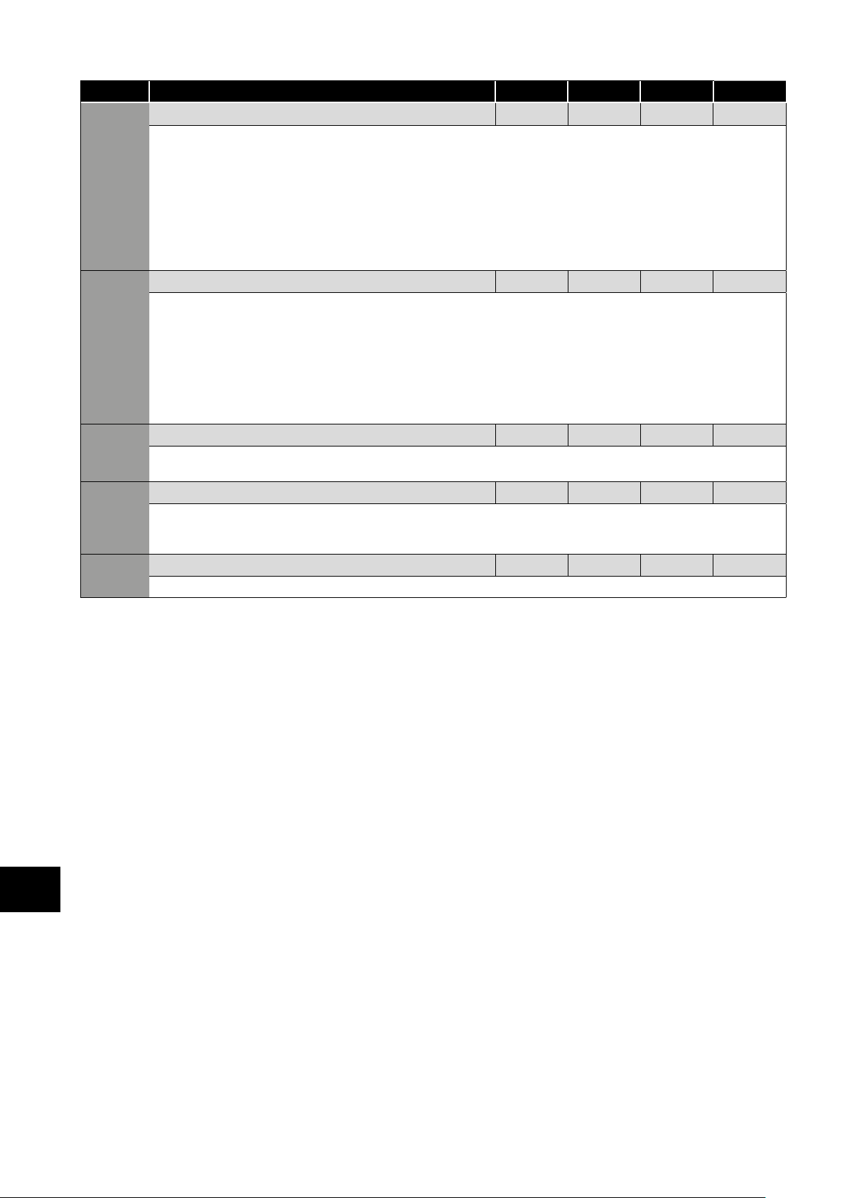
P-46 PI Feedback Source Select 0 5 0 -
Selects the source of the feedback signal to be used by the PI controller.
0: Analog Input 2 (Terminal 4) Signal level readable in P00-02.
1: Analog Input 1 (Terminal 6) Signal level readable in P00-01.
2: Motor Current Scaled as % of P-08.
3: DC Bus Voltage Scaled 0 – 1000 Volts = 0 – 100%.
4: Analog 1 – Analog 2 The value of Analog Input 2 is subtracted from Analog 1 to give a differential signal. The value is
limited to 0.
5: Largest (Analog 1, Analog 2) The larger of the two analog input values is always used for PI feedback.
P-47 Analog Input 2 Signal Format - - - U0-10
= 0 to 10 Volt Signal.
= 0 to 20mA Signal.
= 4 to 20mA Signal, the Optidrive will trip and show the fault code if the signal level falls below 3mA.
= 4 to 20mA Signal, the Optidrive will run at Preset Speed 1 (P-20) if the signal level falls below 3mA.
= 20 to 4mA Signal, the Optidrive will trip and show the fault code if the signal level falls below 3mA.
= 20 to 4mA Signal, the Optidrive will run at Preset Speed 1 (P-20) if the signal level falls below 3mA.
= Use for motor thermistor measurement, valid with any setting of P-15 that has Input 3 as E-Trip. Trip level: 3kΩ, reset 1kΩ.
P-48 Standby Mode Timer 0.0 25.0 0.0 s
When standby mode is enabled by setting P-48 > 0.0, the drive will enter standby following a period of operating at minimum speed
(P-02) for the time set in P-48. When in Standby Mode, the drive display shows , and the output to the motor is disabled.
P-49 PI Control Wake Up Error Level 0.0 100.0 5.0 %
When the drive is operating in PI Control Mode (P-12 = 5 or 6), and Standby Mode is enabled (P-48 > 0.0), P-49 can be used to
define the PI Error Level (E.g. difference between the setpoint and feedback) required before the drive restarts after entering Standby
Mode. This allows the drive to ignore small feedback errors and remain in Standby mode until the feedback drops sufficiently.
P-50 User Output Relay Hysteresis 0.0 100.0 0.0 %
Sets the hysteresis level for P-19 to prevent the output relay chattering when close to the threshold.
Maximum
Default Units
Parameters
6
28 | Optidrive ODE-3 User Guide | Version 2.00 www.invertekdrives.com
Page 29
6.3. Advanced Parameters
Par. Description Minimum
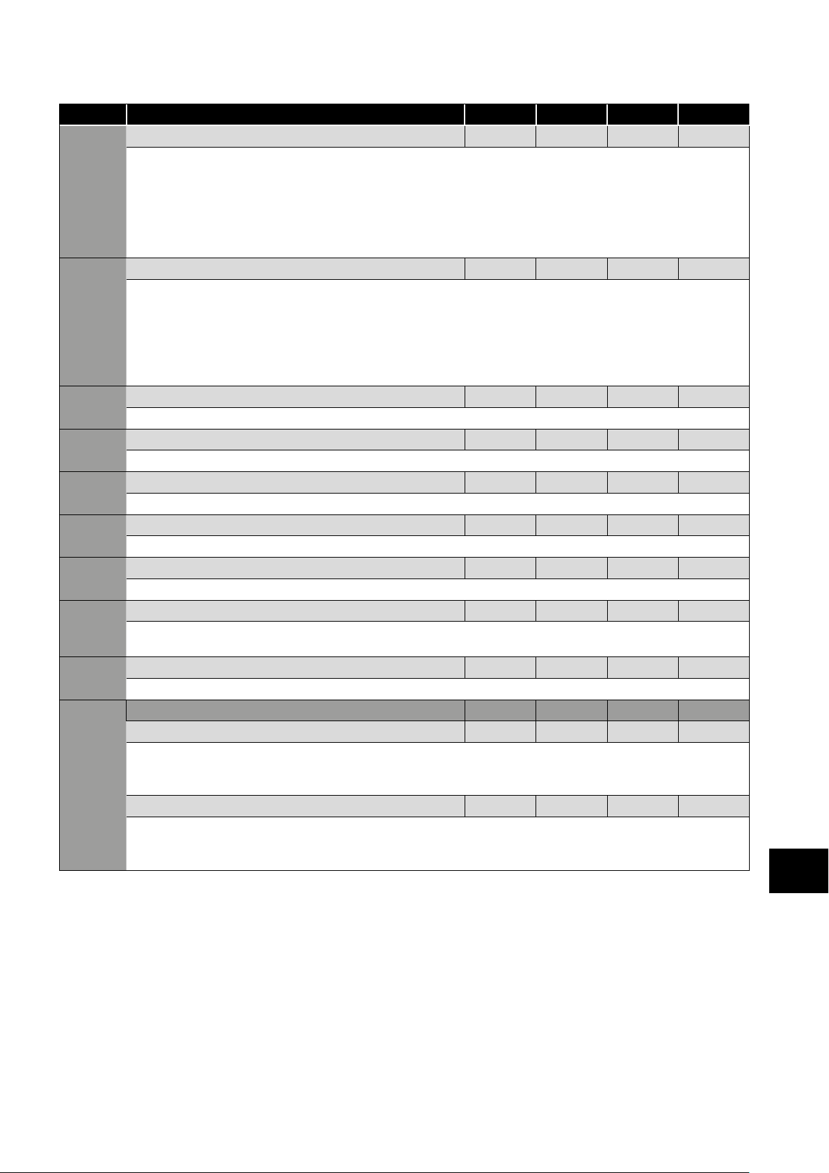
P-51 Motor Control Mode 0 5 0 -
0: Vector speed control mode
1: V/f mode
2: PM motor vector speed control
3: BLDC motor vector speed control
4: Synchronous Reluctance motor vector speed control
5: LSPM motor vector speed control
P-52 Motor Parameter Autotune 0 1 0 -
0: Disabled
1: Enabled. When enabled, the drive immediately measures required data from the motor for optimal operation. Ensure all motor
related parameters are correctly set first before enabling this parameter.
This parameter can be used to optimise the performance when P-51 = 0.
Autotune is not required if P-51 = 1.
For settings 2 – 5 of P-51, autotune MUST be carried out AFTER all other required motor settings are entered.
P-53 Vector Mode Gain 0.0 200.0 50.0 %
Single Parameter for Vector speed loop tuning. Affects P & I terms simultaneously. Not active when P-51 = 1.
P-54 Maximum Current Limit 0.0 175.0 150.0 %
Defines the max current limit in vector control modes
P- Motor Stator Resistance 0.00 655.35 - Ω
Motor stator resistance in Ohms. Determined by Autotune, adjustment is not normally required.
P-56 Motor Stator d-axis Inductance (Lsd) 0.00 655.35 - mH
Determined by Autotune, adjustment is not normally required.
P-57 Motor Stator q-axis Inductance (Lsq) 0.00 655.35 - mH
Determined by Autotune, adjustment is not normally required.
P-58 DC Injection Speed 0.0 P-01 0.0 Hz / RPM
Sets the speed at which DC injection current is applied during braking to Stop, allowing DC to be injected before the drive reaches
zero speed if desired.
P-59 DC Injection Current 0.0 100.0 20.0 %
Sets the level of DC injection braking current applied according to the conditions set in P-32 and P-58.
P-60 Motor Overload Management - - - -
Index 1: Thermal Overload Retention 0 1 0 1
0: Disabled
1: Enabled. When enabled, the drive calculated motor overload protection information is retained after the mains power is
removed from the drive.
Index 2: Thermal Overload Limit Reaction 0 1 0 1
0: It.trp. When the overload accumulator reaches the limit, the drive will trip on It.trp to prevent damage to the motor.
1: Current Limit Reduction. When the overload accumulator reaches 90% of, the output current limit is internally reduced to
1
00% of P-08 in order to avoid an It.trp. The current limit will return to the setting in P-54 when the overload accumulator reaches 10%.
Maximum
Default Units
Parameters
6
Version 2.00 | Optidrive ODE-3 User Guide | 29www.invertekdrives.com
Page 30
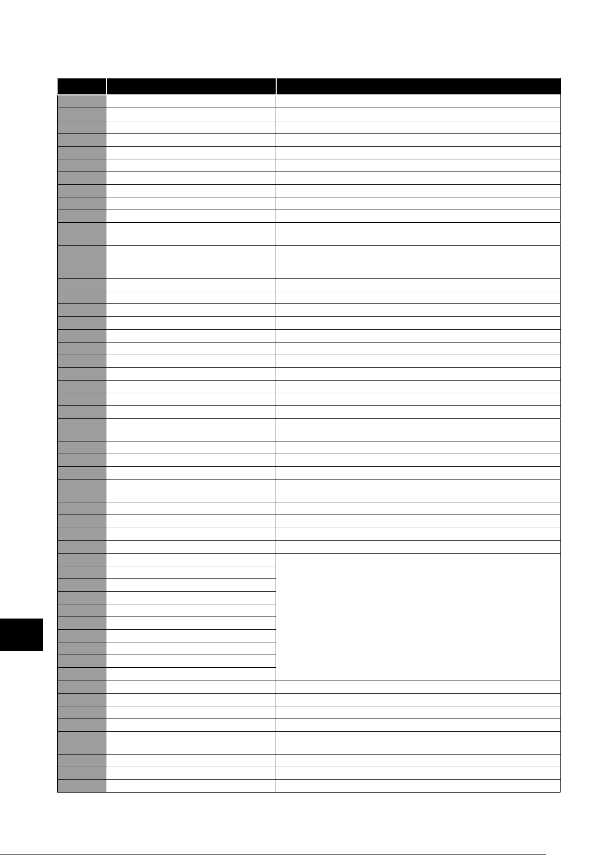
6.4. P-00 Read Only Status Parameters
Par.
P00-01 1st Analog input value (%) 100% = max input voltage
P00-02 2nd Analog input value (%) 100% = max input voltage
P00-03 Speed reference input (Hz / RPM) Displayed in Hz if P-10 = 0, otherwise RPM
P00-04 Digital input status Drive digital input status
P00-05 User PI output (%) Displays value of the User PI output
P00-06 DC bus ripple (V) Measured DC bus ripple
P00-07 Applied motor voltage (V) Value of RMS voltage applied to motor
P00-08 DC bus voltage (V) Internal DC bus voltage
P00-09 Heatsink temperature (˚C) Temperature of heatsink in ˚C
P00-10 Run time since date of manuf. (Hours) Not affected by resetting factory default parameters
P00-11 Run time since last trip (1) (Hours)
P00-12 Run time since last trip (2) (Hours)
P00-13 Trip Log Displays most recent 4 trips with time stamp
P00-14 Run time since last disable (Hours) Run-time clock stopped on drive disable, value reset on next enable
P00-15 DC bus voltage log (V) 8 most recent values prior to trip, 256ms sample time
P00-16 Heatsink temperature log (˚C) 8 most recent values prior to trip, 30s sample time
P00-17 Motor current log (A) 8 most recent values prior to trip, 256ms sample time
P00-18 DC bus ripple log (V) 8 most recent values prior to trip, 22ms sample time
P00-19 Internal drive temperature log (˚C) 8 most recent values prior to trip, 30 s sample time
P00-20 Internal drive temperature (˚C) Actual internal ambient temperature in ˚C
P00-21 CAN process data input Incoming process data (RX PDO1) for CAN: PI1, PI2, PI3, PI4
P00-22 CAN process data output Outgoing process data (TX PDO1) for CAN: PO1, PO2, PO3, PO4
P00-23 Accumulated time with heatsink > 85˚C (Hours) Total accumulated hours and minutes of operation above heatsink temp of 85˚C
P00-24 Accumulated time with drive internal temp >
P00-25 Estimated rotor speed (Hz) In vector control modes, estimated rotor speed in Hz
P00-26 kWh meter / MWh meter Total number of kWh / MWh consumed by the drive
P00-27 Total run time of drive fans (Hours)
P00-28 Software version and checksum Version number and checksum. “1” on LH side indicates I/O processor,
Parameters
6
P00-29 Drive type identifier Drive rating, drive type and software version codes
P00-30 Drive serial number Unique drive serial number
P00-31 Motor current Id / Iq Displays the magnetising current (Id) and torque current (Iq). Press UP to show Iq
P00-32 Actual PWM switching frequency (kHz) Actual switching frequency used by drive
P00-33 Critical fault counter – O-I These parameters log the number of times specific faults or errors occur, and are
P00-34 Critical fault counter – O-Volts
P00-35 Critical fault counter – U-Volts
P00-36 Critical fault counter – O-temp (h/sink)
P00-37 Critical fault counter – b O-I (chopper)
P00-38 Critical fault counter – O-hEAt (control)
P00-39 Modbus comms error counter
P00-40 CANbus comms error counter
P00-41 I/O processor comms errors
P00-42 Power stage uC comms errors
P00-43 Drive power up time (life time) (Hours) Total lifetime of drive with power applied
P00-44 Phase U current offset & ref Internal value
P00-45 Phase V current offset & ref Internal value
P00-46 Phase W current offset & ref Internal value
P00-47 Index 1: Fire mode total active time
P00-48 Scope channel 1 & 2 Displays signals for first scope channels 1 & 2
P00-49 Scope channel 3 & 4 Displays signals for first scope channels 3 & 4
P00-50 Bootloader and motor control Internal value
Description Explanation
Run-time clock stopped by drive disable (or trip), reset on next enable only if a trip
occurred. Reset also on next enable after a drive power down
Run-time clock stopped by drive disable (or trip), reset on next enable only if a trip
occurred (under-volts not considered a trip) – not reset by power down / power
up cycling unless a trip occurred prior to power down
80˚C (Hours)
Index 2: Fire Mode Activation Count
Total accumulated hours and minutes of operation with drive internal ambient
above 80˚C
Time displayed in hh:mm:ss. First value displays time in hrs, press up to display mm:ss
“2“ indicates power stage
useful for diagnostic purposes
Total activation time of Fire Mode
Displays the number of times Fire Mode has been activated
30 | Optidrive ODE-3 User Guide | Version 2.00 www.invertekdrives.com
Page 31
7. Analog and Digital Input Macro Configurations
7.1. Overview
Optidrive E3 uses a Macro approach to simplify the configuration of the Analog and Digital Inputs. There are two key parameters
which determine the input functions and drive behaviour:
P-12 Selects the main drive control source and determines how the output frequency of the drive is primarily controlled.
P-15 Assigns the Macro function to the analog and digital inputs.
Additional parameters can then be used to further adapt the settings, e.g.
P-16 Used to select the format of the analog signal to be connected to analog input 1, e.g. 0 – 10 Volt, 4 – 20mA.
P-30 Determines whether the drive should automatically start following a power on if the Enable Input is present.
P-31 When Keypad Mode is selected, determines at what output frequency / speed the drive should start following the enable
command, and also whether the keypad start key must be pressed or if the Enable input alone should start the drive.
P-47 Used to select the format of the analog signal to be connected to analog input 2, e.g. 0 – 10 Volt, 4 – 20mA.
The diagrams below provide an overview of the functions of each terminal macro function, and a simplified connection diagram for
each.
7.2. Macro Functions Guide Key
The table below should be used as a key for pages 32 to 34.
STOP / RUN Latched input, Close to Run, Open to Stop.
Forward Rotation /
Reverse Rotation
AI1 REF Analog Input 1 is the selected speed reference.
P-xx REF Speed setpoint from the selected preset speed.
PR-REF Preset speeds P-20 – P-23 are used for the speed reference, selected according to other digital input
^-FAST STOP (P-24)-^ When both inputs are active simultaneously, the drive stops using Fast Stop Ramp Time P-24.
E-TRIP External Trip input, which must be Normally Closed. When the input opens, the drive trips showing
(NO) Normally Open Contact, Momentarily Close to Start.
(NC) Normally Closed Contact, momentary Open to Stop.
Fire Mode Activates Fire Mode, see section 7.7. Fire Mode.
ENABLE Hardware Enable Input. In Keypad Mode, P-31 determines whether the drive immediately starts, or the
INC SPD Normally Open, Close the input to Increase the motor speed.
DEC SPD Normally Open, Close input to Decrease motor speed.
KPD REF Keypad Speed Reference selected.
FB REF Selected speed reference from Fieldbus (Modbus RTU / CAN / Master depending on
Selects the direction of motor operation.
status.
or depending on P-47 setting.
keypad start key must be pressed. In other modes, this input must be present before the start signal via
the fieldbus interface.
P-12 setting).
Analog and Digital Input Macro Configurations
7
Version 2.00 | Optidrive ODE-3 User Guide | 31www.invertekdrives.com
Page 32
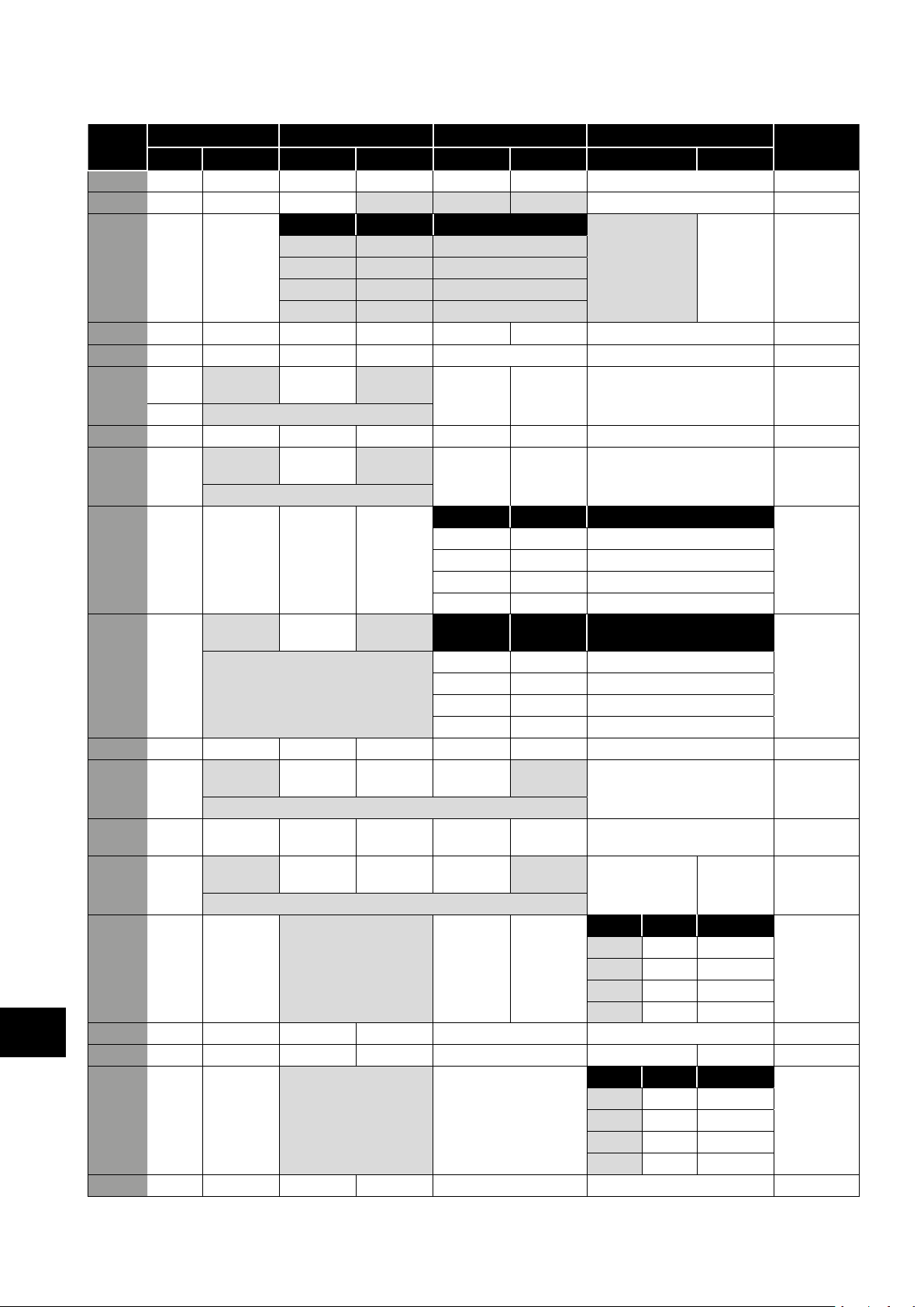
7.3. Macro Functions – Terminal Mode (P-12 = 0)
P-15 DI1 DI2 DI3 / AI2 DI4 / AI1 Diagram
0 1 0 1 0 1 0 1
0 STOP RUN
1 STOP RUN AI1 REF PR-REF P-20 P - 21 Analog Input AI1 1
2 STOP RUN DI2 DI3 PR P-20 - P-23 P -01 2
3 STOP RUN AI1 P-20 REF E-TRIP OK Analog Input AI1 3
4 STOP RUN AI1 AI2 Analog Input AI2 Analog Input AI1 4
5 STOP RUN FWD STOP
FWD REV
0 0 P-20
1 0 P - 21
0 1 P-22
1 1 P- 23
RUN REV
AI1 REF P-20 REF Analog Input AI1 1
AI1 P-20 REF Analog Input AI1 1
Analog and Digital Input Macro Configurations
6 STOP RUN
7 STOP RUN FWD STOP
8 STOP RUN
9 STOP START FWD STOP START REV
10 (NO)
11 (NO)
12 STOP RUN FAST STOP
13 (NO) START FWD STOP (NC) (NO) START REV
14 STOP RUN DI2 E-TRIP OK DI2 DI4 PR 11
7
15 STOP RUN P-23 REF AI1 Fire Mode Analog Input AI1 1
16 STOP RUN P-23 REF P-21 REF Fire Mode FWD REV 2
17 STOP RUN DI2 Fire Mode DI2 DI4 PR 2
18 STOP RUN
^------FAST STOP (P-24)------^
FWD REV
RUN REV
^------FAST STOP (P-24)------^
FWD
^------FAST STOP (P-24)------^ 0 0 P-20
START
START
FWD
^---------------------FAST STOP (P-24)---------------------^
^---------------------FAST STOP (P-24)---------------------^
STOP (NC) AI1 REF P-20 REF Analog Input AI1 5
STOP (NC) (NO)
(P-24)
FWD REV
REV DI3 DI4 PR 2
OK AI1 REF P-20 REF Analog Input AI1 7
E-TRIP OK Analog Input AI1 3
E-TRIP OK Analog Input AI1 3
0 0 P-20
1 0 P- 21
0 1 P-22
1 1 P-23
DI3 DI4 PR 2
1 0 P- 21
0 1 P-22
1 1 P-23
START
REV
Fire Mode Analog Input AI1 1
Analog Input AI1 6
KPD REF P-20 REF 13
0 0 P-20
1 0 P -21
0 1 P-22
1 1 P-23
0 0 P-20
1 0 P -21
0 1 P-22
1 1 P-23
32 | Optidrive ODE-3 User Guide | Version 2.00 www.invertekdrives.com
Page 33
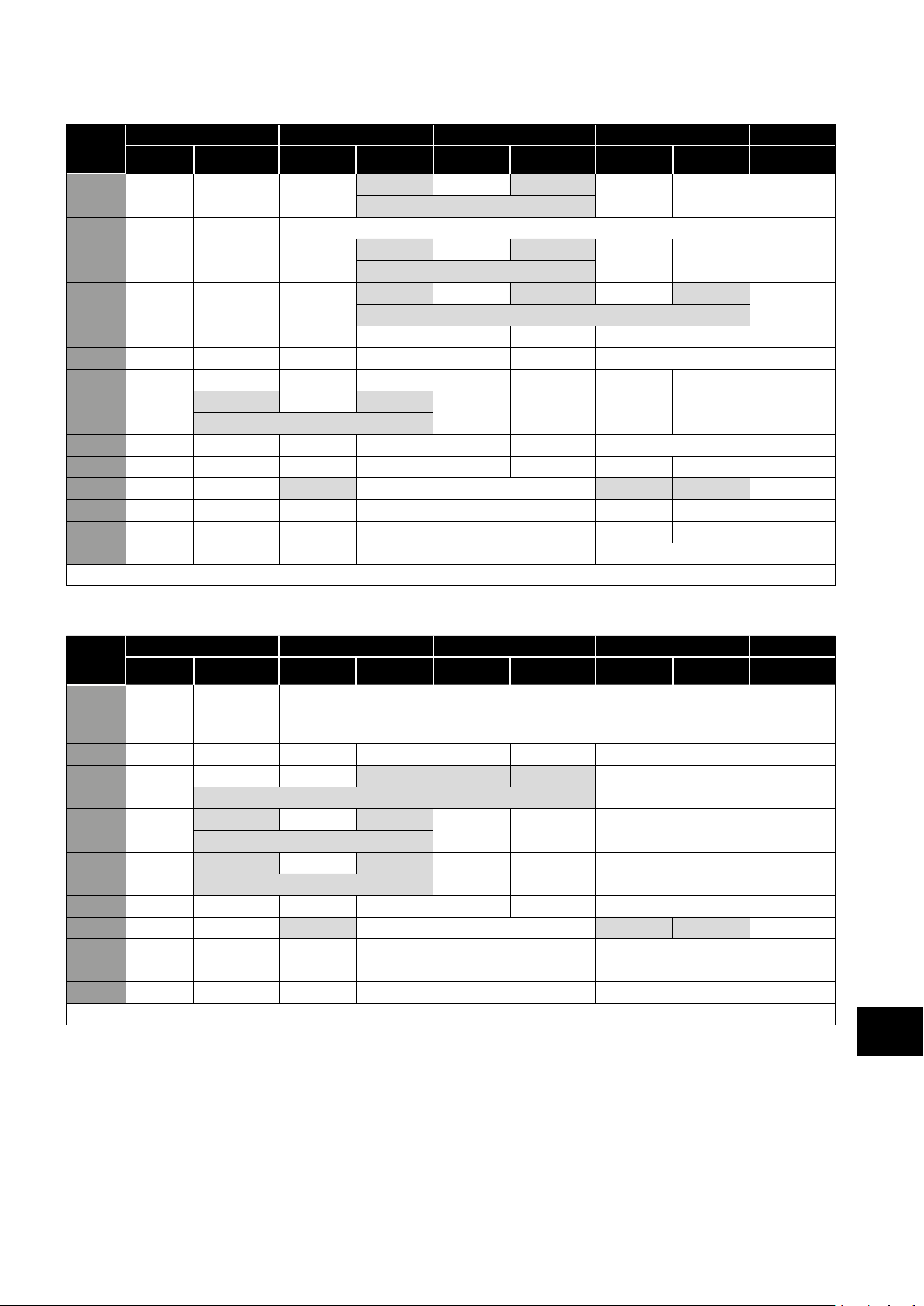
7.4. Macro Functions - Keypad Mode (P-12 = 1 or 2)
P-15
0 STOP ENABLE -
1 STOP ENABLE PI Speed Reference
2 STOP ENABLE -
3 STOP ENABLE -
4 STOP ENABLE -
5 STOP ENABLE
6 STOP ENABLE
7 STOP RUN FWD STOP
8 STOP
14 STOP RUN - - E-TRIP OK - -
15 STOP RUN PR REF KPD REF Fire Mode P-23 P -21 2
16 STOP RUN P-23 REF KPD REF Fire Mode
17 STOP RUN KPD REF P-23 REF Fire Mode
18 STOP RUN AI1 REF KPD REF Fire Mode AI1 1
DI1 DI2 DI3 / AI2 DI4 / AI1 Diagram
0 1 0 1 0 1 0 1
-
-
E-TRIP OK -
KPD REF AI1 REF AI1 10
KPD REF AI1 REF AI1 1
E-TRIP OK KPD REF P-20 REF 11
E-TRIP OK KPD REF P-20 REF 11
KPD REF AI1 REF AI1
DEC SPD FWD REV
DEC SPD
KPD REF P-20 REF 8
DEC SPD
FWD REV
FWD REV
FWD REV
FWD REV
^---------FAST STOP (P-24)---------^
RUN FWD
STOP
INC SPD
^----------------START----------------^
INC SPD
^----------------START----------------^
INC SPD
^-------------------------------START-------------------------------^
INC SPD
RUN REV
RUN REV
9,10,11,12, 13 = 0
8
9
Analog and Digital Input Macro Configurations
2
2
7.5. Macro Functions - Fieldbus Control Mode (P-12 = 3, 4, 7, 8 or 9)
P-15
0 STOP ENABLE FB REF (Fieldbus Speed Reference, Modbus RTU / CAN / Master-Slave
1 STOP ENABLE PI Speed Reference 15
3 STOP ENABLE FB REF P-20 REF E-TRIP OK Analog Input AI1 3
5 STOP ENABLE FB REF PR REF P-20 P - 21 Analog Input AI1 1
6 STOP ENABLE FB REF AI1 REF E-TRIP OK Analog Input AI1 3
7 STOP ENABLE FB REF KPD REF E-TRIP OK Analog Input AI1 3
14 STOP ENABLE - - E-TRIP OK Analog Input AI1 16
15 STOP ENABLE PR REF FB REF Fire Mode P-23 P- 21 2
16 STOP ENABLE P-23 REF FB REF Fire Mode Analog Input AI1 1
17 STOP ENABLE FB REF P-23 REF Fire Mode Analog Input AI1 1
18 STOP ENABLE AI1 REF FB REF Fire Mode Analog Input AI1 1
DI1 DI2 DI3 / AI2 DI4 / AI1 Diagram
0 1 0 1 0 1 0 1
defined by P-12)
^----START (P-12 = 3 or 4 Only)----^
^----START (P-12 = 3 or 4 Only)----^
^----START (P-12 = 3 or 4 Only)----^
2,4,8,9,10,11,12,13 = 0
14
7
Version 2.00 | Optidrive ODE-3 User Guide | 33www.invertekdrives.com
Page 34
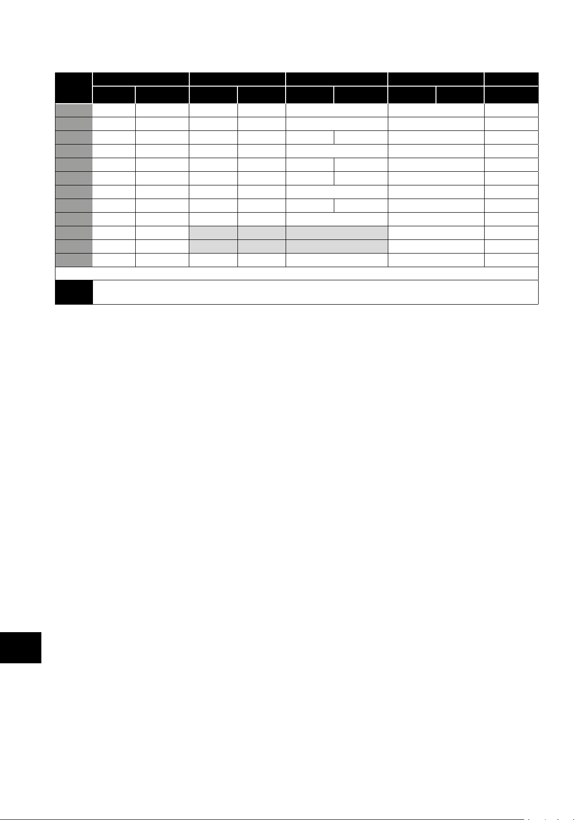
7.6. Macro Functions - User PI Control Mode (P-12 = 5 or 6)
P-15
0 STOP ENABLE PI REF P-20 REF AI2 AI1 4
1 STOP ENABLE PI REF AI1 REF AI2 (PI FB) AI1 4
3, 7 STOP ENABLE PI REF P-20 E-TRIP OK AI1 (PI FB) 3
4 (NO) START (NC) STOP AI2 (PI FB) AI1 12
5 (NO) START (NC) STOP PI REF P-20 REF AI1 (PI FB) 5
6 (NO) START (NC) STOP E-TRIP OK AI1 (PI FB)
8 STOP RUN
14 STOP RUN - - E-TRIP OK AI1 (PI FB) 16
15 STOP RUN P-23 REF PI REF Fire Mode AI1 (PI FB) 1
16 STOP RUN P-23 REF P-21 REF Fire Mode AI1 (PI FB) 1
17 STOP RUN P-21 REF P-23 REF Fire Mode AI1 (PI FB) 1
Analog and Digital Input Macro Configurations
18 STOP RUN AI1 REF PI REF Fire Mode AI1 (PI FB) 1
NOTE
0 1 0 1 0 1 0 1
P1 Setpoint source is selected by P-44 (default is fixed value in P-45, A11 may also be selected).
P1 Feedback source is selected by P-46 (default is A12, other options may be selected).
7.7. Fire Mode
The Fire Mode function is designed to ensure continuous operation of the drive in emergency conditions until the drive is no longer
capable of sustaining operation. The Fire Mode input may be a normally open (Close to Activate Fire Mode) or Normally Closed
(Open to Activate Fire Mode) according to the setting of P-30 Index 2. In addition, the input may be momentary or maintained type,
selected by P-30 Index 3.
This input may be linked to a fire control system to allow maintained operation in emergency conditions, e.g. to clear smoke or
maintain air quality within that building.
The fire mode function is enabled when P-15 = 15, 16 or 17, with Digital Input 3 assigned to activate fire mode.
Fire Mode disables the following protection features in the drive:
O-t (Heat-sink Over-Temperature), U-t (Drive Under Temperature), Th-FLt (Faulty Thermistor on Heat-sink), E-trip (External Trip),
4-20 F (4-20mA fault), Ph-Ib (Phase Imbalance), P-Loss (Input Phase Loss Trip), SC-trp (Communications Loss Trip), I.t-trp (Accumulated
overload Trip).
The following faults will result in a drive trip, auto reset and restart:
O-Volt (Over Voltage on DC Bus), U-Volt (Under Voltage on DC Bus), h O-I (Fast Over-current Trip), O-I (Instantaneous over current
on drive output), Out-F (Drive output fault, Output stage trip).
DI1 DI2 DI3 / AI2 DI4 / AI1 Diagram
FWD REV
2,9,10,11,12,13 = 0
AI2 (PI FB) AI1 4
7
34 | Optidrive ODE-3 User Guide | Version 2.00 www.invertekdrives.com
Page 35
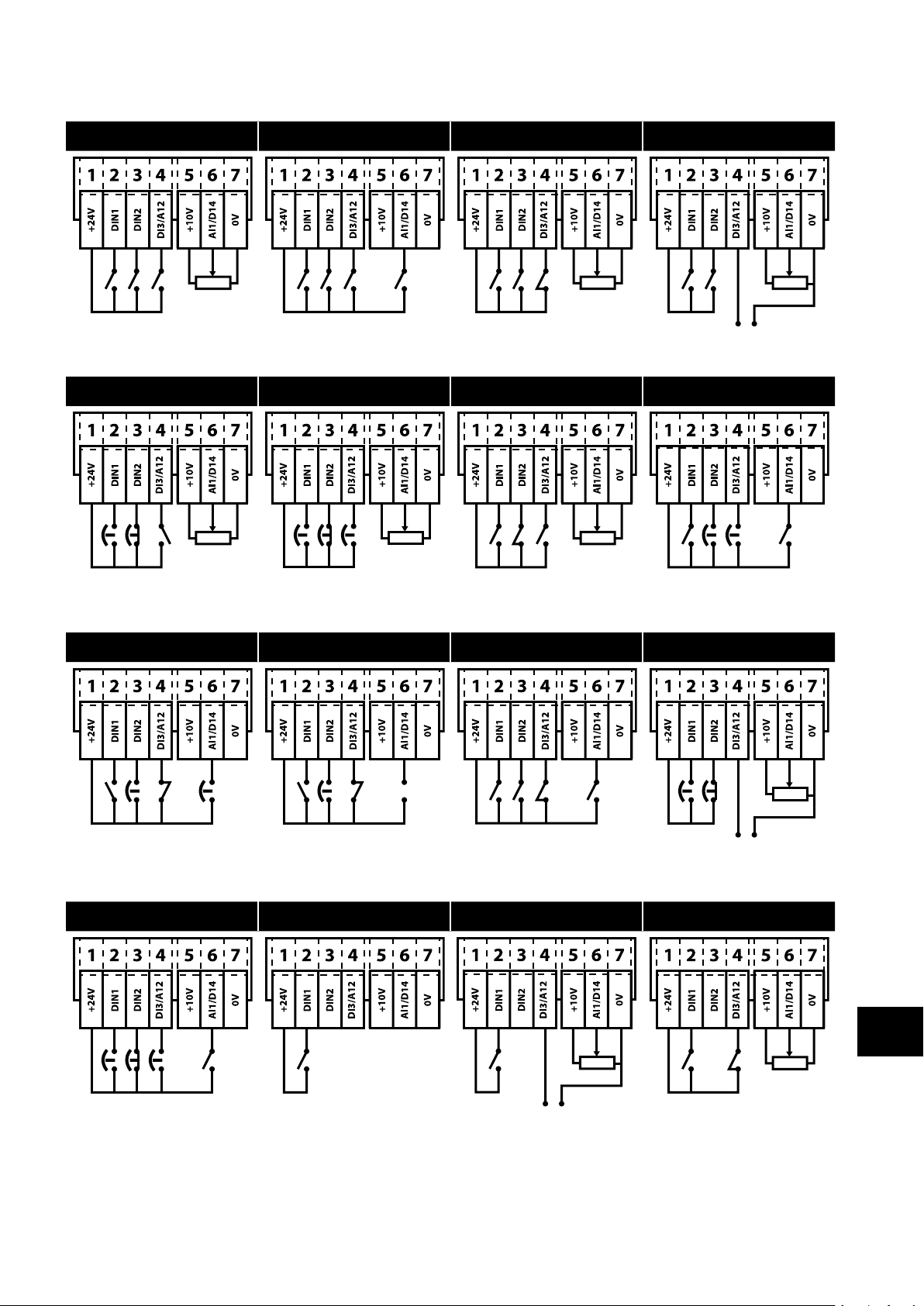
7.8. Example Connection Diagrams
Diagram 1 Diagram 2 Diagram 3 Diagram 4
P-16 = 0 – 10V,
4- 20mA, etc.
(NC) P-16 = 0 – 10V
4- 20mA, etc.
P-47 = 0 – 10V, P-16 = 0 – 10V,
4- 20mA, etc. 4- 20mA, etc
Diagram 5 Diagram 6 Diagram 7 Diagram 8
(NO) (NC)
Close Open
Start Stop
(NO) (NC) (NO)
Close Open Close
FWD Stop REV
(NC)
Open Fast Stop
P-24
(NO) (NO)
Speed
Diagram 9 Diagram 10 Diagram 11 Diagram 12
Analog and Digital Input Macro Configurations
(NO) (NC) (NO)
Speed Open Speed
E-Trip
(NO) (NC) (NC)
Open
Trip
(NO) (NC) P-47= P-16=
Close Open 0-10V 0-10V
Start Stop 4-20mA 4-20mA
Diagram 13 Diagram 14 Diagram 15 Diagram 16
(NO) (NC) (NO)
Close Open Close
FWD Stop REV
P-47= P-16=
0-10V 0-10V
4-20m 4-20m
Version 2.00 | Optidrive ODE-3 User Guide | 35www.invertekdrives.com
7
(NC) P-16=
Open 0-10V
Trip 4-20mA
Page 36
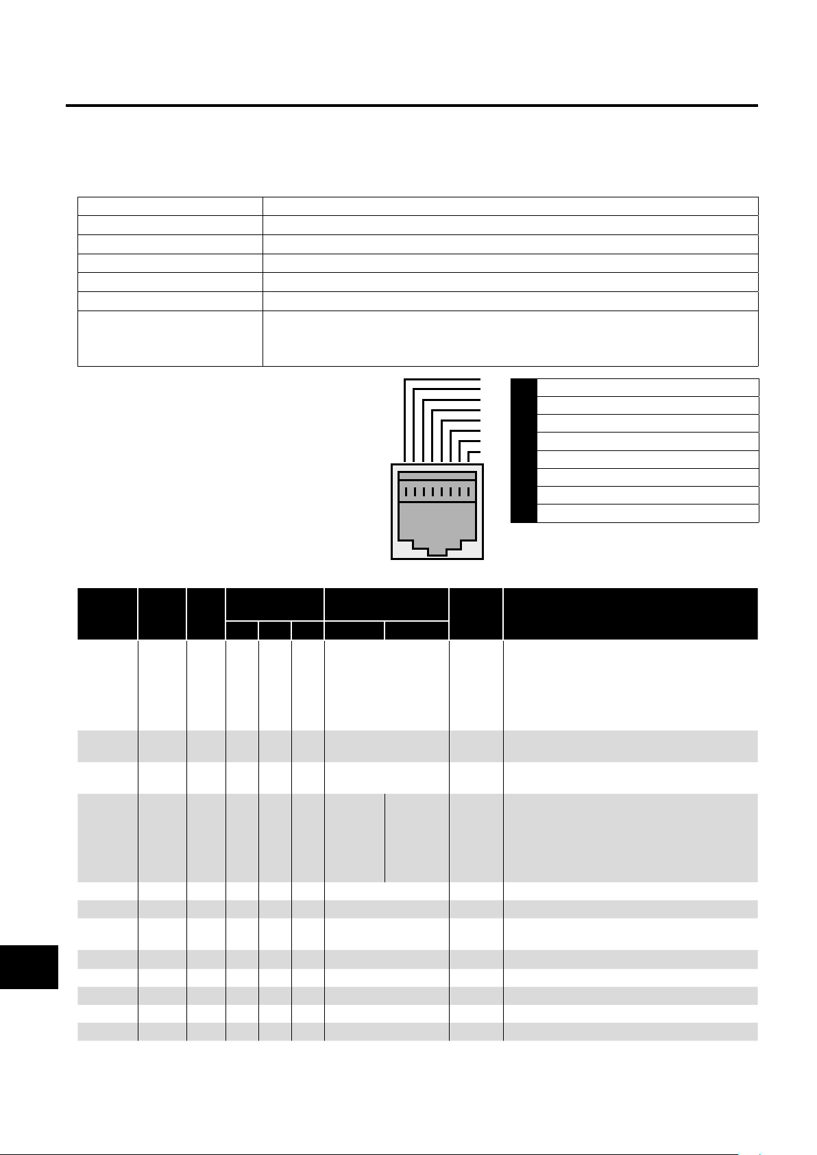
8. Modbus RTU Communications
8.1. Introduction
The Optidrive E3 can be connected to a Modbus RTU network via the RJ45 connector on the front of the drive.
8.2. Modbus RTU Specification
Protocol Modbus RTU
Error check CRC
Baud rate 9600bps, 19200bps, 38400bps, 57600bps, 115200bps (default)
Data format 1 start bit, 8 data bits, 1 stop bits, no parity
Physical signal RS 485 (2-wire)
User interface RJ45
Supported Function Codes 03 Read Multiple Holding Registers
06 Write Single Holding Register
16 Write Multiple Holding Registers (Supported for registers 1 – 4 only)
8.3. RJ45 Connector Configuration
For full MODBUS RTU register map information please
refer to your Invertek Drives Sales Partner. Local contacts
can be found by visiting our website:
www.invertekdrives.com
When using MODBUS control the Analog and Digital
Inputs can be configured as shown in section 7.5.
Macro Functions - Fieldbus Control Mode (P-12 = 3, 4,
7, 8 or 9).
8.4. Modbus Register Map
Modbus RTU Communications
8
Register
Number
1 - R/W
2 - R/W
4 - R/W
6 - R
7 R
8 R
11 - R
20
21 P00-02 R
22 P00-03 R
23 P00-08 R
24 P00-09 R
Par.
P00-01 R
Type
All user configurable parameters are accessible as Holding Registers, and can be Read from or Written to using the appropriate Modbus
command. The Register number for each parameter P-04 to P-60 is defined as 128 + Parameter number, e.g. for parameter P-15, the register
number is 128 + 15 = 143. Internal scaling is used on some parameters, for further details please contact your Invertek Drives Sales Partner.
Supported
Function Codes
03 06 16
✔ ✔ ✔
✔ ✔ ✔
✔ ✔ ✔
✔
✔
✔
✔
✔
✔
✔
✔
✔
1 CAN -
2 CAN +
3 0 Volts
4 -RS485 (PC)
5 +RS485 (PC)
6 +24 Volt
7 -RS485 (Modbus RTU)
8 +RS485 (Modbus RTU)
Warning: This is not an Ethernet connection.
Do not connect directly to an Ethernet port.
Function
Low Byte High Byte
Drive Control Command 0..3 16 Bit Word.
Modbus Speed
reference setpoint
Acceleration and
Deceleration Time
Error code Drive status
Output Motor Frequency
Output Motor Current 0..480
Digital input status 0..15 Indicates the status of the 4 digital inputs
Analog Input 1 value 0..1000 Analog input % of full scale x10, e.g. 1000 = 100%
Analog Input 2 value 0..1000 Analog input % of full scale x10, e.g. 1000 = 100%
Speed Reference Value 0..1000
DC bus voltage 0..1000 DC Bus Voltage in Volts
Drive temperature 0..100 Drive heatsink temperature in °C
Range Explanation
Bit 0: Low = Stop, High = Run Enable
Bit 1: Low = Decel Ramp 1 (P-04),
High = Decel Ramp 2 (P-24)
Bit 2: Low = No Function, High = Fault Reset
Bit 3: Low – No Function, High = Coast Stop Request
0..5000 Setpoint frequency x10, e.g. 100 = 10.0Hz
0..60000
0..20000
Ramp time in seconds x 100, e.g. 250 = 2.5 seconds
Low Byte = Drive Error Code, see section 10.1. Fault
Code Messages
High Byte = Drive Status as follows:
0: Drive Stopped
1: Drive Running
2: Drive Tripped
Output frequency in Hz x10, e.g. 100 = 10.0Hz
Output Motor Current in Amps x10, e.g. 10 = 1.0 Amps
Lowest Bit = 1 Input 1
Displays the setpoint frequency x10, e.g. 100 = 10.0Hz
36 | Optidrive ODE-3 User Guide | Version 2.00 www.invertekdrives.com
Page 37
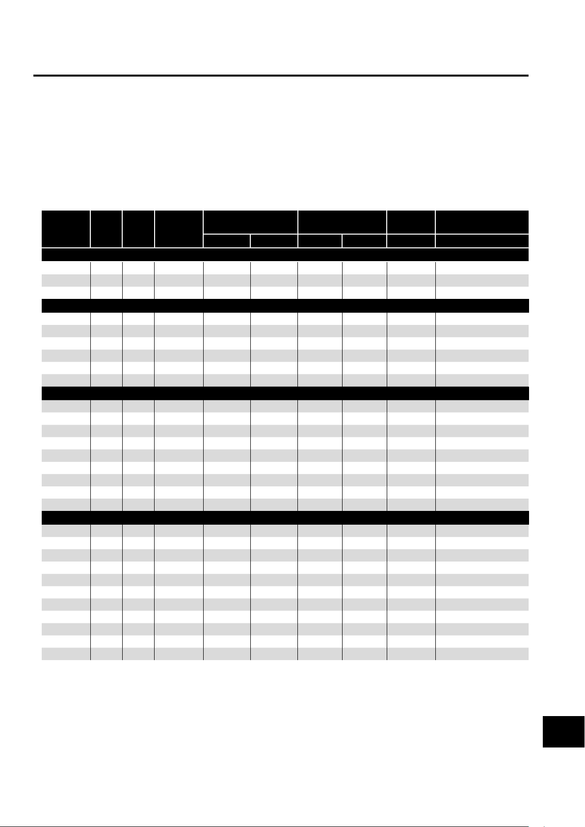
9. Technical Data
9.1. Environmental
Operational ambient temperature range Open Drives : -10 … 50°C (frost and condensation free)
Enclosed Drives : -10 ... 40°C (frost and condensation free)
Storage ambient temperature range : -40 … 60°C
Maximum altitude : 2000m. Derate above 1000m: 1% / 100m
Maximum humidity : 95%, non-condensing
NOTE For UL compliance: the average ambient temperature over a 24 hour period for 200-240V, 2.2kW and 3HP, IP20 drives is 45°C.
9.2. Rating Tables
Frame
Size
110 - 115 (+ / - 10%) V 1 Phase Input, 230V 3 Phase Output (Voltage Doubler)
1 0.37 0.5 7. 8 10 10 8 8 2.3 1 0 . 75 1 15. 8 25 20 8 8 4.3 2 1.1 1.5 21 . 9 32 30 8 8 5.8 100
200 - 240 (+ / - 10%) V 1 Phase Input, 3 Phase Output
1 0.37 0.5 3.7 10 6 8 8 2.3 -
1 0 . 75 1 7. 5 10 10 8 8 4.3 1 1.5 2 12 .9 16 17. 5 8 8 7 2 1.5 2 12 .9 16 17. 5 8 8 7 100
2 2.2 3 19 . 2 25 25 8 8 10.5 50
3 4 5 29.2 40 40 8 8 15 .3 25
200 - 240 (+ / - 10%) V 3 Phase Input, 3 Phase Output
1 0.37 0.5 3.4 6 6 8 8 2.3 1 0 . 75 1 5.6 10 10 8 8 4.3 1 1.5 2 9.5 16 15 8 8 7 2 1.5 2 8.9 16 15 8 8 7 100
2 2.2 3 12 .1 16 17. 5 8 8 10.5 50
3 4 5 20.9 32 30 8 8 18 25
3 5.5 7. 5 26.4 40 35 8 8 24 20
4 7. 5 10 33.3 40 45 16 5 30 15
4 11 15 50.1 63 70 16 5 46 10
380 - 480 (+ / - 10%)V 3 Phase Input, 3 Phase Output
1 0 . 75 1 3.5 6 6 8 8 2.2 1 1.5 2 5.6 10 10 8 8 4.1 2 1.5 2 5.6 10 10 8 8 4.1 250
2 2.2 3 7. 5 16 10 8 8 5.8 200
2 4 5 11 . 5 16 15 8 8 9.5 12 0
3 5.5 7. 5 17. 2 25 25 8 8 14 10 0
3 7. 5 10 21. 2 32 30 8 8 18 80
3 11 15 2 7.5 40 35 8 8 24 50
4 15 20 34.2 40 45 16 5 30 30
4 18.5 25 44.1 50 60 16 5 39 22
4 22 30 51.9 63 70 16 5 46 22
kW HP Input
Current
Fuse / MCB (Type B) Maximum Cable
Size
Non UL UL mm AWG A Ω
Output
Current
Recommended
Brake Resistance
Technical Data
NOTE Cable sizes shown are the maximum possible that may be connected to the drive. Cables should be selected according to
local wiring codes or regulations at the point of installation.
9.3. Single Phase Operation of Three Phase Drives
All drive models intended for operation from three phase mains power supply (e.g. model codes ODE-3-xxxxxx-3xxx) may be
operated from a single phase supply at up to 50% of maximum rated output current capacity.
In this case, the AC power supply should be connected to L1 (L) and L2 (N) power connection terminals only.
Version 2.00 | Optidrive ODE-3 User Guide | 37www.invertekdrives.com
9
Page 38
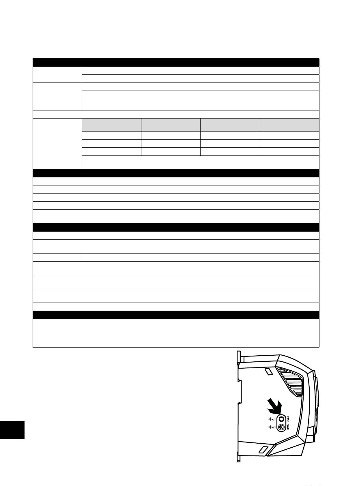
9.4. Additional Information for UL Compliance
Optidrive E3 is designed to meet the UL requirements. For an up to date list of UL compliant products, please refer to UL listing
NMMS.E226333. In order to ensure full compliance, the following must be fully observed.
Input Power Supply Requirements
Supply Voltage 200 – 240 RMS Volts for 230 Volt rated units, + /- 10% variation allowed. 240 Volt RMS Maximum.
Imbalance Maximum 3% voltage variation between phase – phase voltages allowed.
Frequency 50 – 60Hz + / - 5% Variation
Short Circuit Capacity
Mechanical Installation Requirements
All Optidrive E3 units are intended for indoor installation within controlled environments which meet the condition limits shown in section 9.1. Environmental.
The drive can be operated within an ambient temperature range as stated in section 9.1. Environmental.
For IP20 units, installation is required in a pollution degree 1 environment.
For IP66 (Nema 4X) units, installation in a pollution degree 2 environment is permissible.
Frame size 4 drives must be mounted in an enclosure in a manner that ensures the drive is protected from 12.7mm (1/2 inch) of deformation of the
enclosure if the enclosure impacted.
Electrical Installation Requirements
Incoming power supply connection must be according to section 4.3. Incoming Power Connection.
Suitable Power and motor cables should be selected according to the data shown in section 9.2. Rating Tables and the National Electrical Code
or other applicable local codes.
Motor Cable 75°C Copper must be used.
Power cable connections and tightening torques are shown in sections 3.3. Mechanical Dimensions and Mounting – IP20 Open Units and 3.5.
Mechanical Dimensions – IP66 (Nema 4X) Enclosed Units.
Integral Solid Sate short circuit protection does not provide branch circuit protection. Branch circuit protection must be provided in accordance
with the national electrical code and any additional local codes. Ratings are shown in section 9.2. Rating Tables
Transient surge suppression must be installed on the line side of this equipment and shall be rated 480Volt (phase to ground), 480 Volt (phase to
phase), suitable for over voltage category iii and shall provide protection for a rated impulse withstand voltage peak of 4kV.
UL Listed ring terminals / lugs must be used for all bus bar and grounding connections.
General Requirements
Optidrive E3 provides motor overload protection in accordance with the National Electrical Code (US).
• Where a motor thermistor is not fitted, or not utilised, Thermal Overload Memory Retention must be enabled by setting P-50 = 1.
•
Where a motor thermistor is fitted and connected to the drive, connection must be carried out according to the information shown in section
4.9.2. Motor Thermistor Connection.
Technical Data
9.5. EMC Filter Disconnect
Drives with an EMC filter have an inherently higher leakage current to Ground (Earth).
For applications where tripping occurs the EMC filter can be disconnected (on IP20 units only)
by completely removing the EMC screw on the side of the product.
Remove the screw as indicated right.
The Optidrive product range has input supply voltage surge suppression components fitted
to protect the drive from line voltage transients, typically originating from lightning strikes or
switching of high power equipment on the same supply.
When carrying out a HiPot (Flash) test on an installation in which the drive is built, the
9
voltage surge suppression components may cause the test to fail. To accommodate this
type of system HiPot test, the voltage surge suppression components can be disconnected by
removing the VAR screw After completing the HiPot test, the screw should be replaced and
the HiPot test repeated. The test should then fail, indicating that the voltage surge suppression
components are once again in circuit.
380 – 480 Volts for 400 Volt rated units, + / - 10% variation allowed, Maximum 500 Volts RMS.
All Optidrive E3 units have phase imbalance monitoring. A phase imbalance of > 3% will result in the drive tripping. For
input supplies which have supply imbalance greater than 3% (typically the Indian sub-continent & parts of Asia Pacific
including China) Invertek Drives recommends the installation of input line reactors.
Voltage Rating Min kW (HP) Max kW (HP) Maximum supply
short-circuit current
115 V 0.37 (0.5) 1.1 (1.5) 100kA rms (AC)
230V 0.37 (0.5) 11 (15) 100kA rms (AC)
400 / 460V 0.75 (1) 22 (30) 100kA rms (AC)
All the drives in the above table are suitable for use on a circuit capable of delivering not more than the above specified
maximum short-circuit Amperes symmetrical with the specified maximum supply voltage when protected by Class J fuses.
38 | Optidrive ODE-3 User Guide | Version 2.00 www.invertekdrives.com
Page 39
10. Troubleshooting
10.1. Fault Code Messages
Fault
Code
No. Description Suggested Remedy
00 No Fault Not required.
01 Brake channel over current Check external brake resistor condition and connection wiring.
02 Brake resistor overload The drive has tripped to prevent damage to the brake resistor.
03 Output Over Current Instantaneous Over current on the drive output. Excess load or shock load on the motor.
NOTE Following a trip, the drive cannot be immediately reset. A delay time is inbuilt,
which allows the power components of the drive time to recover to avoid damage.
04
Motor Thermal Overload (I2t)
05 Power stage trip Check for short circuits on the motor and connection cable
06 Over voltage on DC bus Check the supply voltage is within the allowed tolerance for the drive. If the fault occurs
07 Under voltage on DC bus The incoming supply voltage is too low. This trip occurs routinely when power is removed
08 Heatsink over temperature The drive is too hot. Check the ambient temperature around the drive is within the drive
09 Under temperature Trip occurs when ambient temperature is less than -10°C. Temperature must be raised
10 Factory Default parameters
loaded
11 External trip E-trip requested on digital input 3. Normally closed contact has opened for some reason.
12 Optibus comms loss Check communication link between drive and external devices. Make sure each drive in
13 DC bus ripple too high Check incoming supply phases are all present and balanced.
14 Input phase loss trip Check incoming power supply phases are present and balanced.
15 Output Over Current Check for short circuits on the motor and connection cable.
16 Faulty thermistor on heatsink
17 Internal memory fault (IO) Press the stop key. If the fault persists, consult you supplier.
18 4-20mA Signal Lost Check the analog input connection(s).
19 Internal memory fault (DSP) Press the stop key. If the fault persists, consult you supplier.
21 Motor PTC thermistor trip Connected motor thermistor over temperature, check wiring connections and motor.
22 Cooling Fan Fault (IP66 only) Check / replace the cooling fan.
23
Drive internal temperature too high
26 Output Fault Indicates a fault on the output of the drive, such as one phase missing, motor phase
40 Autotune Fault The motor parameters measured through the autotune are not correct.
41
42
43
44
50 Modbus comms loss fault Check the incoming Modbus RTU connection cable.
51 CAN comms loss trip Check the incoming CAN connection cable.
The drive has tripped after delivering >100% of value in P-08 for a period of time to
prevent damage to the motor.
on deceleration or stopping, increase the deceleration time in P-04 or install a suitable
brake resistor and activate the dynamic braking function with P-34.
from the drive. If it occurs during running, check the incoming power supply voltage and
all components in the power feed line to the drive.
specification. Ensure sufficient cooling air is free to circulate around the drive.
over -10°C in order to start the drive.
If motor thermistor is connected check if the motor is too hot.
the network has its unique address.
Note: Following a trip, the drive cannot be immediately reset. A delay time is inbuilt,
which allows the power components of the drive time to recover to avoid damage.
Drive ambient temperature too high, check adequate cooling air is provided.
currents not balanced. Check the motor and connections.
Check the motor cable and connections for continuity.
Check all three phases of the motor are present and balanced.
Check that at least one register is being polled cyclically within the timeout limit set in
P-36 Index 3.
Check that cyclic communications take place within the timeout limit set in P-36 Index 3.
Troubleshooting
NOTE Following an over current or overload trip (3, 4, 5, 15), the drive may not be reset until the reset time delay has elapsed to prevent
damage to the drive.
Version 2.00 | Optidrive ODE-3 User Guide | 39www.invertekdrives.com
10
Page 40

Ñ82-E3MAN-IN_V2.00ZÓ
82-E3MAN-IN_V2.00
Invertek Drives Ltd. Offa's Dyke Business Park, Welshpool, Powys SY21 8JF United Kingdom
Tel: +44 (0)1938 556868 Fax: +44 (0)1938 556869
www.invertekdrives.com
 Loading...