

Page 1
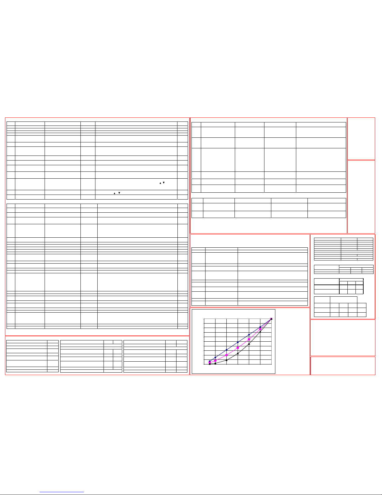
DIGITAL INPUTS – TERMINAL MODE (P-12 = 0, 3 or 4)
P-19 Input 1 function Input 2 function Input 3 function Additional Information
0
Open: Stop (disable)
Closed: Run (enable)
Open: Analog input
Closed: Speed Preset 1
Volts / Current analog input
The format of the current analog input is
defined by P-16, if P-16 is set to 0-10V a 420mA format will be assumed when input 3
closed
1 Open: Stop (disable)
Closed: Run (enable)
Open: Analog input
Closed: Speed Preset 1/2,
(Digital Input 3 selects)
Open: Speed Preset 1
Closed: Speed Preset 2
2 Open: Stop (disable)
Closed: Run (enable)
Digital Input 2: Open \
Digital Input 3: Open /
Digital Input 3: Open \
Digital Input 2: Closed /
Digital Input 3: Closed \
Digital Input 2: Open /
Digital Input 3: Closed \
Digital Input 2: Closed /
► Selects Speed Preset 1
► Selects Speed Preset 2
► Selects Speed Preset 3
► Selects Speed Preset 4
3
Open: Stop (disable)
Closed: Run (enable)
External trip input:
Open: TRIP; Closed: OK
Open: Analog Input
Closed: Speed Preset 1
4
Normally Open (N.O.)
Momentarily Close to run
Normally Closed (N.C.)
Momentarily Open to stop
Open: Analog Input
Closed: Speed Preset 1
5
Open: Stop (disable)
Closed: Run (enable)
Close to run
Open to fast stop (P-07)
Open: Analog Input
Closed: Speed Preset1
Wire break mode. Fast stop (P-07) activated
when input 1 & input 2 closed at same time.
DIGITAL INPUTS – KEYPAD MODE (P-12 = 1 or 2)
P-19 Input 1 function Input 2 function Input 3 function Additional Information
0,1,2,4,5
Open: Stop (disable)
Closed: Run (enable)
Closed: remote up pushbutton Closed: remote down pushbutton
Closing inputs 2 & 3 at same time
starts the drive.
3
Open: Stop (disable)
Closed: Run (enable)
External trip input:
Open: TRIP; Closed: no trip
Open: Keypad speed reference
Closed: Preset / Jog Speed 1
Speed reference is set by
pushbuttons.
TROUBLESHOOTING
TO CLEAR A TRIP CONDITION
Remove the condition which caused the trip and press the STOP key or re-enable the drive.
The drive will restart according to the mode selected by P-30.
If the motor is stopped and the display shows STOP, there is no fault; the drive output is disabled and the drive is ready to run.
Fault Code What has happened What to do
P-deF Default parameters loaded Press STOP key, drive is ready to configure for particular application
O-I
Over current on drive output.
Excess load on the motor.
Over temperature on the
heatsink
Motor at constant speed: investigate overload or malfunction. Motor
starting: load stalled or jammed. Check for star-delta motor wiring error.
Motor accelerating/decelerating: The accel/decel time too short
requiring too much power. If P-03 or P-04 cannot be increased, a bigger
drive is needed
O-Uolt Over voltage on DC bus Supply problem, or increase decel ramp time P-04.
U-Uolt Under voltage on DC bus
This occurs routinely when power is switched off. If it occurs during
running, check power supply voltage.
I.t-trP
The drive has tipped on
overload after delivering
greater than 100% load for a
period of time.
Check to see when the decimal points are flashing (drive in overload)
and either decrease acceleration rate or load. Check cable length is
within specification.
th-Flt Faulty thermistor on heatsink. Refer to your IDL Authorised Distributor.
E-triP
External trip (on dig. input 2 or
3)
External trip on digital input – see P-19 (motor thermistor?)
EE-F
EEPROM fault. Parameters not
saved, defaults reloaded.
Try again. If problem recurs, refer to your IDL Authorised Distributor.
PS-Trp Internal power stage fault
Check wiring to motor, look for ph-ph or ph-Earth short circuit.
Check drive ambient temp, additional space or cooling needed?
Check drive is not forced into overload.
O-t Heatsink over temperature Check drive ambient temp. Additional space or cooling needed?
Iin-F
Current analog input out of
range
Check input current in range defined by P-16
PARAMETER ZERO
• Provides a read only window into the motor control software
allowing key internal values to be viewed. This is useful for
following signals through the drive control system when
troubleshooting.
• Access, scroll, change and exit are as for any other parameter.
The selected variable is at the left hand side of the display.
• There are 9 different windows listed below:
1 Unscaled analog input (%) 7 Applied motor voltage (V)
2 Speed ref. via scaled analog I/P(Hz) 8 DC bus voltage (V)
3 Pre-ramp speed ref. (Hz) 9 Internal thermistor
4 Post-ramp speed ref. (Hz) (NTC) value
5 Not used
6 Stator field frequency (Hz)
OPTIDRIVE E1/EF1 SIZE 1 - 115V Input Voltage OPTIDRIVE E1/EF1 SIZE 1 - 230V Input Voltage OPTIDRIVE E1/EF1 SIZE 2 - 110V/240V Input Voltage
GENERAL TECHNICAL
DATA
• Supply frequency 48
to 62 Hz.
• Max. permissible 3-
phase supply
imbalance 3%.
• Max. ambient
temperature 50 oC.
• Max. altitude 2000 m.
• Derate above 1000 m,
1% / 100 m.
• Derate output current
5%/ oC above max.
ambient temp up to
55oC
• I x t protection above
100% output current.
• 150% overload
protection for 60 sec.
• 175% overload
allowable for 2 sec.
• Storage temperature -
40 to +60 oC
OPTIDRIVE DIMENSIONS & TORQUE SETTINGS
Size 1 Size 2
Length mm / in 155 / 6.10” 260 / 10.24”
Width mm / in 80 / 3.15” 100 / 3.98”
Depth mm / in 130 / 5.12” 175 / 6.89”
Weight kg / lb 1.1 / 2.42 2.6 / 5.72
A mm / in 72 / 2.83” 92 / 3.62”
B mm / in 4 / 0.16”
C mm / in 25 / 0.98”
D mm / in 105 / 4.13” 210 / 8.27”
Fixings 2 * M4 (2 x 8-32)
Power terminal torque settings 1 Nm/ 8.86 in.lbs 1 Nm/ 8.86 in.lbs
ENCLOSURE - NON VENTED DIMENSIONS
SEALED UNIT
DRIVE POWER RATING
W H D
Size 1 115V / 230V 300/11.81” 400/15.75” 200/9.84”
Size 2 115V / 230V 450/17.72” 600/23.62” 300/11.81”
ENCLOSURE – VENTED DIMENSIONS
VENTED UNIT
DRIVE POWER RATING
W H D
Size 1 All ratings
300/
11.81”
400/
15.75”
150/
5.91”
Size 2 All ratings
400/
15.75”
600/
23.62”
250
9.42”
DRIVE
POWER
RATING
FORCE VENTED (WITH
FAN)
W H D
Air
Flow
Size 1 All
ratings
200/
7.87”
300/
11.81”
150/
5.91”
> 15m3
/ h
Size 2 All
ratings
300
11.81”
400/
15.75”
250/
9.84”
> 45m3
/ h
Model OD E1-xxxxx-IN/USA
12037 /
12050
12075 /
12100
Supply voltage +/- 10% 220-240
Phases 1
Motor output rating
kW Hp
0.37
0.5
0.75
1
Output Amps A 4.3 7
Fuse or Circuit Breaker
rating
A 10 20
Max ambient temperature
o
C 8kHz
o
C 16kHz
o
C 32kHz
40
30
40
30
Motor cable size, Cu 75C AWG 16 14
Max motor cable length m/ ft 50 / 160’
STANDARD PARAMETER SET
Par. Description Range Default Explanations Set to
P-01 Maximum speed P-02 to 5*P-09 (max 500Hz) 50Hz Maximum speed limit – Hz or rpm. See P-10
P-02 Minimum speed 0 to P-01 (max 500Hz) 10Hz Minimum speed limit – Hz or rpm. See P-10
P-03 Accel ramp time (s) 0 to 3,000s 5s Acceleration ramp time from 0 to base speed (P-9) in seconds
P-04 Decel ramp time (s) 0 to 3,000s 5s Deceleration ramp time from base speed (P-9) to 0 in seconds
P-05 Stop mode select
0, 2: Ramp stop
1: Coast to stop
0
If the supply is lost and P-05=0 then the drive will try to continue running by reducing
the speed of the load using the load as a generator.
If P-05=2, the drive ramps at P-07 to stop.
P-06 V/F characteristic
0: Constant torque, INDUSTRIAL
1..10: Pump/fan, HVAC
0
Either V = kf (linear) or V = kf 2 (pumps / fans with HVAC rating). Note when P-06 is set
to 1 the ramps are automatically set to 60 s.
P-07 Fast stop (s) 0.0 to 25s. (Disabled when 0.0s) 0.0s
Deceleration ramp time after mains loss (P-05 = 0 or 2) or when fast stop activated
(see P-19).
When P-05 = 2 and P-07 = 0, activating the fast stop disables the drive without braking
(effectively coasting to stop).
P-08 Motor rated current 25% -100% of drive current rating Drive rating
Rated (nameplate) current of the motor (Amps). In HVAC (P-06 = 1) mode, the rated
motor current limit is increased, allowing P-08 to be set to a higher level
P-09 Motor rated frequency 25Hz to 500Hz
50 Hz
(60Hz - HP)
Rated (nameplate) frequency of the motor. Changing P-09 resets P-02, P-10, P-26 & P28 to 0, & P-01=P-09.
P-10 Motor rated speed
0, P-09*12 to P-09*60
eg for 50Hz motor, range is 600 to
3000 rpm
0
When non-zero, speed is displayed in rpm in parameters P-01, P-02, P-20…P-23,
P-27 and P-28
P-11 Voltage boost 0 to 25% of max output voltage 3%
Applies an adjustable boost to the Optidrive voltage output at low speed to assist
with starting ‘sticky’ loads. For continuous applications at low speed use a forced
ventilated motor.
P-12 Terminal or Keypad control
0: Terminal control
1: Keypad control – fwd only
2: Keypad control − fwd and rev
3: Terminal control
4: Not used
0 (Terminal
control)
When P-12 = 2, the keypad START key toggles between forward and reverse. When
stopped, target speed can be accessed / changed using the STOP & , buttons.
3: Terminal control
P-13 Trip log Last four trips stored Read only
Most recent 4 trips stored in order of occurrence, ie on entry, display shows most
recent first. Press or to step through all four
P-14 Extended menu access Code 0 to 9999 0
Set to “101” (default) for extended menu access. Change code in P-37 to prevent
unauthorised access to the Extended Parameter Set
EXTENDED PARAMETER SET
Par. Description Range Default Explanations Set to
P-15 Motor rated voltage
115V product: 40V to 150V
230V product: 40V to 250V
115V for 115V
230V for 230V
When P-15 is non-zero, the applied motor voltage is controlled and scaled so that
the specified voltage is achieved at rated freq (P-09)
P-16 Analog input format (V / mA)
Voltage: 0-10V, 10-0V
Current: 4-20mA, 0-20mA, 20-4mA
0-10V
Analog input format (on terminal 6). If a current input format is set & P-19=0, Digital
input 3 must be closed for the current input to be configured.
P-17 Switching frequency 8, 16, 32 kHz 16 kHz
Effective power stage switching frequency. Improvements in acoustic noise and
output current waveform occur with increasing switching frequency at the expense
of increased losses within the drive
P-18 Relay output function
0: Drive enabled
1: Drive healthy (not tripped)
2: Motor at set speed
3: Motor speed > zero
4: Motor at max speed (P-01)
5: Motor current overload
1
Relay output function. Contacts closed if selected condition is true.
When P-18= 3, (zero speed), the relay contacts close when the output frequency is
greater than 5% of base frequency.
The drive is in overload when the motor current exceeds P-08
P-19
Digital inputs function
select
0 to 5, See digital input table 0 Defines function of digital inputs (see also P-16 and Digital Inputs table)
P-20 Preset speed 1 -P-02 (min) to P-01 (max) 50hz/rpm Defines Speed Preset1
P-21 Preset speed 2 -P-02 (min) to P-01 (max) 0 Hz/rpm De fi nes Speed Preset 2
P-22 Preset speed 3 -P-02 (min) to P-01 (max) 0 Hz/rpm De fi nes Speed Preset 3
P-23 Preset speed 4 -P-02 (min) to P-01 (max) 0 Hz/rpm De fi nes Speed Preset 4
P-24 Reserved
P-25 Analog output function (A) 0:Motor Speed 1:Motor current
(D) 2:Drive enabled 3: Set speed 0
Analog output select. When P-25 = 0 then 10V = 100% of P-01, or if P-25 =1 then 10V
= 200% of P-08.
P-25 = 2 or 3 gives a 10V digital output.
P-26 Reserved
P-27 Skip freq / speed P-02 (min) to P-01 (max) 0 (inactive)
Centre point for skip frequency band. The skip frequency band defined by P-27, P-
28 is mirrored around zero for negative speeds.
P-28 Skip freq / speed band 0 to100% of rated speed/freq. P-09 0 Hz / rpm Width of skip frequency band, the center of which is defined by P-27.
P-29 Reserved
P-30 Drive start mode
Edge-r: Close Digital input 1 after
power up to start drive
Auto-0: drive runs whenever
Digital input 1 closed.
Auto-1..4: as Auto-0, except 1..4
Attempts to restart after a
trip
Auto-0
When set to Edge-r, if drive is powered up with Digital Input 1 closed (enabled),
drive will not run. The switch must be opened & closed after power up or after a
clearing a trip for the drive to run.
When set to Auto-0, drive will run whenever digital input 1 is closed (if not tripped).
Auto-1..4 makes 1..4 attempts to automatically restart after a trip (25s between
attempts). If fault has cleared drive will restart. Drive must be powered down, reset
on the keypad or reset by re-enabling the drive to reset auto-reset counter.
When P-12 is set to 1 or 2, P-30 changes automatically to Edge-r.
P-31 Boost frequency 0 to 250Hz 50Hz Optidrive1ph start up frequency maintained during the startup boost period
P-32 Boost duration 0 to 25s 2s Time for which the startup boost period is maintained
P-33 Boost start voltage 0 to 100% 20%
% of operational motor voltage applied at start of startup boost period. The applied
voltage is increased to the operational voltage at end of startup boost period.
P-34 Reserved
P-35 Analog input scaling factor 25% to 500%
80% at 50Hz,
84% at 60Hz
Scales the analog input at control terminal 6 up or down, or the digital reference in
keypad (or Slave) mode up or down (see P-12).
P-36 Drive address (s-comms) 0 to 63 (0=disable) 1 Distinct drive address for serial comms. 0 = comms disabled
P-37 Access code definition 0 to 9999 101 Defines Extended Parameter Set access code, P-14
P-38 Parameter access lock
0: Parameters can be changed,
auto-saved on power down
1: Parameter changes not saved
on power down
2: Read-only. No changes allowed.
0 (write
access and
auto-save are
enabled)
Controls user access to parameters. WhenP-38 = 0, all parameters can be changed
and these changes will be stored automatically. When P-38 = 1, changes may be
made but these will not be stored when the Optidrive1ph powers down. When P-38
= 2, parameters are locked and cannot be changed thus preventing unauthorised
access.
P-39 Hours run meter 0 to 99999 hours Read only Not affec te d b y reset-to-default command
P-40 Software checksum 0000 to FFFF (hex) Read only Drive rating, drive type and software version codes
OPTIDRIVE - E OPTIONS
The following additional
products are available:
Internal and external
EMC filters to meet EN
61000-6-3 / -4 for
conducted emissions
Dual relay output and
dual analog input,
2ROUT& 2ANIN
Feedback control card,
PICON
Enclosed (IP55)
Optidrives
Optidrive Coolplate
with heatsink removed
for mounting to a cooled
surface
FURTHER INFORMATION
The Website, www.invertek.co.uk, contains the following
information:
General product information, including Product and Options
Manuals
Application notes and Software product upgrade files
Company and IDL authorised dealer information
V
oltage / Frequency (V/f)
Characteristic
The V/f characteristic is defined by
parameter P-06 as shown.
Increasing the value of P-06
decreases the volts applied to the
motor at a given frequency;
reducing the voltage reduces the
amount of current flowing in the
motor hence the torque at the
motor shaft. This feature is used to
save energy in applications where
the torque required at low speeds
is less than at higher speeds. A
particular value of P-06 should be
determined by trial and error.
Optidrive E V/F Curves
0.0%
10.0%
20.0%
30.0%
40.0%
50.0%
60.0%
70.0%
80.0%
90.0%
100.0%
0 102030405060
Frequency
% of Full Output Voltage
P-06=0
P-06=5
P-06=10
Model ODE1-xxxxx-USA 11050
Supply voltage +/- 10% 110-11 5
Phases 1
Motor output rating
KW
HP
0.37
0.5
Output Amps A 7.0
Fuse or Circuit Breaker
rating
A 10
Max ambient temperature
o
C 8kHz
o
C 16kHz
o
C 32kHz
40
30
Motor cable size, Cu 75C AWG 14
Max motor cable length m/ ft 50 / 160’
Model ODE1-xxxxx-IN/USA 21075
22110 /
22150
Supply voltage +/- 10% 110-115 220-240
Phases 1
Motor output rating
HP
kW
3/4
0.55
1.5
1.1
Output current A 10.5 10.5
Fuse or circuit breaker
rating
A 20 20
Max ambient
temperature
o
C 8kHz
o
C 16kHz
o
C 32kHz
40
30
40
30
Motor cable size, Cu 75C AWG 14 14
Max motor cable length m/ft 100 / 320’ 100 / 320’
Page 2
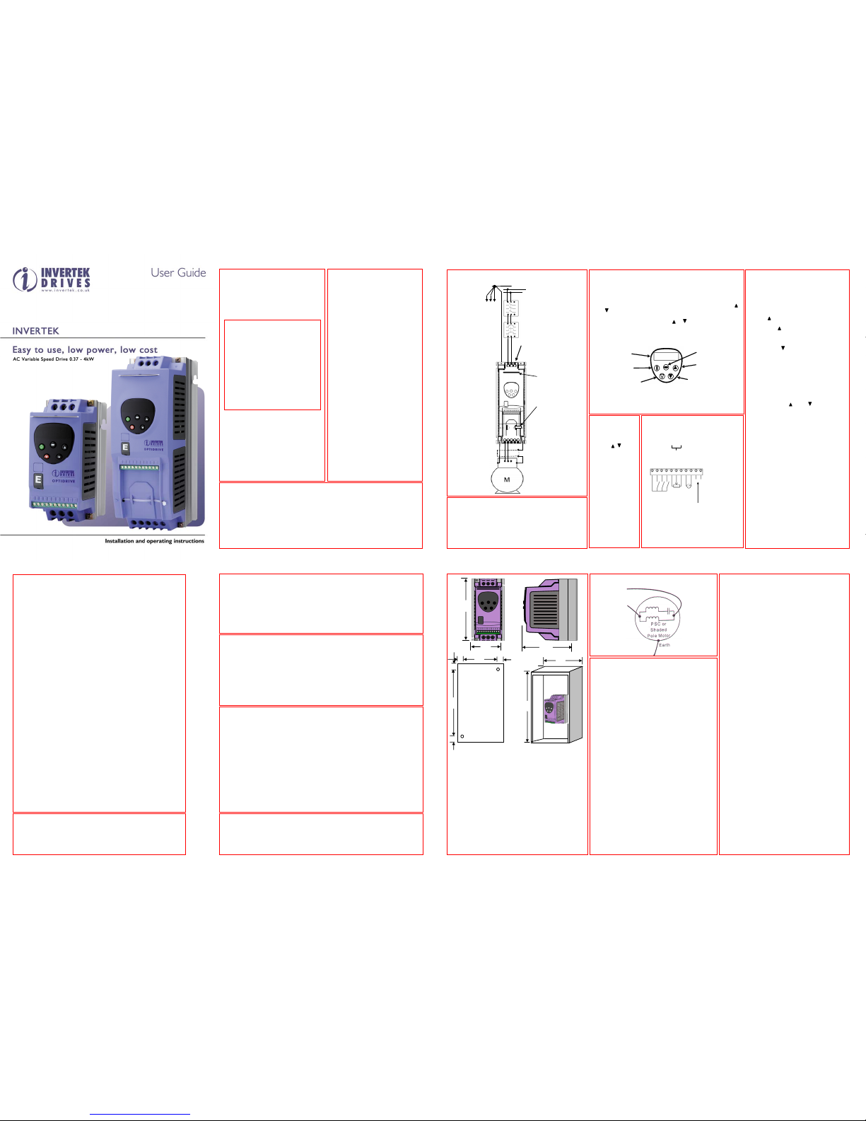
OPERATING IN KEYPAD MODE
Set P-12 = 1(this allows the Optidrive to be
controlled from the keypad):
Enable the drive by closing digital input
1. The display will show StoP.
Press the START key. The display shows
H 0.0.
Press to increase speed
The drive will run forward, increasing
speed until is released.
CAUTION: the rate of acceleration is
controlled by the setting of P-03, check
this before starting.
Either Press to decrease speed
The drive will decrease speed until τ is
released. The rate of deceleration is
limited by the setting in P-04
Or Press the STOP key. The drive will
decelerate to rest at the rate set in P-04.
The display will finally show StoP at
which point the drive is disabled
To preset a target speed prior to enable
press the stop key whilst the drive is
stopped. The display will show the target
speed, use the and to adjust as
required then press the Stop key to return
the display to StoP. Pressing the START
key will start the drive accelerating to the
target speed.
The operation of the keypad can be duplicated
using remote pushbuttons connected to the
control terminals, see Application Note AN21.
In this mode, if P30 is set to Auto-0..4, then
the drive will run as soon as the drive enable
is applied (terminal 1 & 2 is closed).
TO SAVE CHANGES to Parameter settings,
switch the power supply off and wait for the
drive to power down (screen blank) before
switching on.
NOTE that this assumes P-38 = 0 (default). If
P-38 = 1, changes are not saved.
STANDARDS CONFORMITY
The Optidrive E conforms with the following standards
1) CE marked for low voltage directive
2) UL508C Power conversion equipment
3) IEC 664-1 Insulation coordination for equipment within low voltage systems
4) EN61800-3 Adjustable Speed electrical power drive systems – Part 3 (EMC)
5) EN 61000-6 / -2, -3, -4 Generic Immunity / Emissions standards (EMC)
Earth
N
Isolator
Contactor,
mcb or
Fuses
Screened motor
cable connects to
motor frame earth
L
U V W
Optidrive E1 size 2
Help card
Cable
management
tie-wrap
L N
U V W
Each drive star
connected to system
earth point
To
other
drives
E
OPERATION – BASICS + GETTING STARTED
PSC MOTOR WIRING
CONTROL TERMINAL BLOCK Default Status
+10V O/P
Digital I/P 1
Digital I/P 2
Digital I/P 3
+10V O/P
Analog I/P
0V
Analog O/P
0V
Relay contact
Relay common
Closed: Enable; Open: Disable
500 Ω
min.
0-10V
analog
O/P
Relay ratings
30V dc, 5A
240V ac, 5A
0-10V
4-20mA
1 2 3 4 5 6 7 8 9 10 11
Analog I/P - Closed: A; Open :V
losed: Preset 1; Open: Analog I/P
WARNING
The STOP function does not remove potentially lethal high voltages. ISOLATE the drive and
wait 10 minutes before starting any work on it
Parameter P-01 can be se t to operate the motor at up to 3,000 rpm, hence use this parameter
with care
If it is desired to operate the drive at any frequency/speed above the rated speed (P-09/ P-10)
of the motor, consult the manufacturers of the motor and the driven machine about suitability
for over-speed operation
The fan (if fitted) to the heatsink of the Optidrive starts automatically when the heatsink
temperature reaches approximately 40ºC. When the heatsink is at room temperature the fan
will be stopped.
MECHANICAL INSTALLATION
Optidrives can be installed side-by-side with their heatsink
flanges touching. This gives adequate ventilation space between
them. If the Optidrive is to be installed above another drive or
any other heat-producing device, the minimum vertical spacing
is 100mm. The enclosure should either be force-ventilated or
large enough to allow natural cooling (allow 0.1 m3 per kW of
drive rating).
GROUNDING (EARTHING)
The ground terminal of each Optidrive should be individually
connected DIRECTLY to the site earth (ground) busbar (through
the filter if installed) as shown. Optidrive ground connections
should not loop from one drive to another, or to, or from any
other equipment. Ground loop impedance must conform to local
industrial safety regulations. To meet UL regulations, UL
approved ring crimp terminals should be used for all earth wiring
connections.
EASY START-UP
When delivered, the Optidrive is in the default state,
meaning that it is set to operate in terminal mode and
all parameters (P-xx) have the default values as
shown overleaf.
Connect a control switch between the control
terminals 1 and 2.
Connect a potentiometer (500 Ω min to 10 kΩ max)
between terminals 5 and 7, and wiper to terminal 6.
Set the control switch between pins 1 and 2 open
so that the drive is ‘disabled’.
With the potentiometer set to ze ro, switch on the
supply to the drive. The display will show StoP.
Close the control switch, terminals 1-2. The drive is
now ‘enabled’ and the output frequency/speed are
controlled by the potentiometer. The display shows
zero speed in Hz (H 0.0) with the potentiometer
turned to minimum.
Turn the potentiometer to maximum. The motor will
accelerate to 50Hz (the default value of P-01) under
the control of the accelerating ramp time P-03. The
display shows H 50.0 (50Hz) at max speed.
To display motor current (A), briefly press the
Navigate key ⇔.
Press ⇔ again to return to speed display.
To stop the motor, either turn the potentiometer back
to zero or disable the drive by opening the control
switch (terminals 1-2).
If the enable/disable switch is opened the drive will
decelerate to stop at which time the display will show
StoP. If the potentiometer is turned to zero and the
enable/disable is closed the display will show 0.0Hz, if
left like this for 20 seconds the drive will go into
standby mode, display shows Stndby, waiting for a
speed reference.
User Guide
All rights reserved. No part of this User Guide may be reproduced
or transmitted in any form or by any means, electrical or
mechanical including photocopying, recording or by any
information storage or retrieval system without permission in
writing from the publisher.
Copyright Invertek Drives Ltd © 2005
The manufacturer accepts no liability for any consequences
resulting from inappropriate, negligent or incorrect installation, or
adjustment of the optional operating parameters of the drive or
from mismatching of the drive to the motor.
The contents of this User Guide are believed to be correct at the
time of printing. In the interests of a commitment to a policy of
continuous improvement, the manufacturer reserves the right to
change the specification of the product or its performance or the
contents of the User Guide without notice.
SAFETY
This variable speed drive product (Optidrive) is intended for
professional incorporation into complete equipment or systems. If
installed incorrectly it may present a safety hazard. The Optidrive
uses high voltages and currents, carries a high level of stored
electrical energy, and is used to control mechanical plant that may
cause injury. Close attention is required to system design and
electrical installation to avoid hazards in either normal operation
or in the event of equipment malfunction.
System design, installation, commissioning and maintenance
must be carried out only by personnel who have the necessary
training and experience. They must read carefully this safety
information and the instructions in this Guide and follow all
information regarding transport, storage, installation and use of
the Optidrive, including the specified environmental limitations.
Please read the IMPORTANT SAFETY INFORMATION below, and
all Warning and Caution boxes elsewhere.
SAFETY NOTICES
WARNING is given where there is a hazard that could lead to injury
or death of personnel
CAUTION is given where there is a hazard that could lead to
damage to equipment
CAUTION
Carefully inspect the Optidrive before
installation to ensure it is undamaged
Store the Optidrive in its box until
required. Storage should be clean and
dry Temp. Range –40oC to +60oC
Install the Optidrive on a flat, vertical,
flame-resistant vibration-free mounting
within a suitable enclosure, according to
EN60529 if specific Ingress Protection
ratings are required. Installation required
in a pollution degree 2 environment.
Flammable material should not be
placed close to the drive
The entry of conductive or flammable
foreign bodies should be prevented
Max. ambient temperature 50
o
C, min. –
5oC. Refer to table on reverse side.
Relative humidity must be less than 95%
(non-condensing).
The Optidrive is suitable for use on a
circuit capable of delivering not more
than 5KA (50Hp) / 10KA (51-200HP)
symmetrical amperes, 480V maximum.
WARNING
Optidrives should be installed only by qualified electrical persons and in accordance with
local and national regulations and codes of practice. The Optidrive has an Ingress Protection
rating of IP20. For higher IP ratings, use a suitable enclosure.
Electric shock hazard! Disconnect and ISOLATE the Optidrive before attempting any work on
it. High voltages are present at the terminals and within the drive for up to 10 minutes after
disconnection of the electrical supply
Where supply to the drive is through a plug and socket connector, do not disconnect until 10
minutes have elapsed after turning off the supply
Ensure correct earthing connections
The earth cable must be sufficient to carry the maximum supply fault current which normally
will be limited by the fuses or MCB
SAFETY NOTICES
It is the responsibility of the installer to
ensure that the equipment or system into
which the product is incorporated complies
with the EMC legislation of the country of
use. Within the European Union, equipment
into which this product is incorporated must
comply with 89/336/EEC,Electromagnetic
Compatibility.
WARRANTY
All Invertek Drives Ltd (IDL) products carry a
2-year warranty, valid from the date of
manufacture.
Complete Warranty Terms and Conditions
are available upon request from your IDL
Authorised Distributor.
WARNING The level of integrity offered by
the Optidrive control functions – for
example stop/start, forward/reverse and
maximum speed, is not sufficient for use
in safety-critical applications without
independent channels of protection. All
applications where malfunction could
cause injury or loss of life must be subject
to a risk assessment and further
protection provided where needed. Within
the European Union, all machinery in
which this product is used must comply
with Directive 89/392/EEC, Safety of
Machinery. In particular, the electrical
equipment should comply with EN60204-1.
OPTIDRIVE E1
Inver tek D rive s Ltd Tel: +4 4 (0 ) 193 8 556 868
Offa’s Dyke Business Park Fax: +44 (0) 1938 556869
Welshpool
Powys email: [email protected]
SY21 8JF Int erne t:www.invertek.co.uk
UK
Iss2.01
ELECTRICAL INSTALLATION
Connect drive according to diagram (above), ensuring that
motor terminal box connections are correct (see diagram,
below).
Refer to the ELECTRICAL DATA overleaf for the sizes of
cabling and wiring.
It is recommended that the power cabling should be 3-core or
4-core PVC-insulated screened cable, laid in accordance with
local industrial regulations and codes of practice.
CAUTION
Ensure that the supply voltage, frequency and no. of phases (1 or 3 phase) correspond to
the rating of the Optidrive as delivered.
An isolator should be installed between the power supply and the drive.
Never connect the mains power supply to the Output terminals U,V,W.
Protect the drive by using slow-blowing HRC fuses or MCB located in the mains supply of
the drive
Do not install any type of automatic switchgear between the drive and the motor
Wherever control cabling is close to power cabling, maintain a minimum separation of 100
mm and arrange crossings at 90o
Ensure that screening or armouring of power cables is effected in accordance with the
connections diagram below
Ensure that all terminals are tightened to the appropriate torque (see table)
W
D
ENCLOSURE
W
D
H
HOLE
POSITIONS
FOR
MOUNTING
A
B
B
C
D
C
OPERATION – USING THE KEYPAD
MANAGING THE KEYPAD
When the drive is delivered from the factory, only the Standard
Parameter Set (see overleaf) is accessible.
To access the Standard Parameter Set, press the Navigate key ⇔ for
>1 sec.
• Scroll through P-01 to P-14 (and roll over to P-01) by pressing
or
• To display the parameter value, press ⇔
• To edit the parameter value, press or
• To return to the parameter number, press ⇔
• To store a value and / or exit from edit mode, press ⇔ for >1 sec
or press no button for >20 sec.
To access the Extended Parameter Set, set P-14 = 101 and press ⇔
NOTE To restrict unauthorised access, make P-37 = any value from 0
to 9999.
• When in the Extended Parameter Set (except P-00), the display
will revert to normal if no button is pressed for >20 sec.
Refer to the
Digital Inputs
table overleaf
for details of
the digital input
functions 1 to 3
If screened
cabling is used
for the control
wiring, connect
the cable
screen to 0V of
drive, terminals
7 or 9.
IMPORTANT SAFETY INFORMATION
Safety of machinery, and safety-critical applications
Optidrive hardware and software are designed and tested to a high standard and failures are
unlikely.
Electromagnetic Compatibility (EMC)
Optidrive is designed to high standards of EMC. EMC data is provided in a separate EMC
Data Sheet, available on request. Under extreme conditions, the product might cause or
suffer disturbance due to electromagnetic interaction with other equipment. It is the
responsibility of the installer to ensure that the equipment or system into which the product
is incorporated complies with the EMC legislation of the country of use. Within the European
Union, equipment into which this product is incorporated must comply with 89/336/EEC,
Electromagnetic Compatibility.
When installed as recommended in this User Guide, the radiated emissions levels of all
Optidrives are less than those defined in the Generic radiated emissions standard EN610006-4. When fitted with an optional internal filter, the conducted emission levels are less than
those defined in the Generic radiated emissions standard EN61000-6-3 (class B) for
screened cable lengths of < 1m and with EN61000-6-4 (class A) for screened cable lengths of
< 5m.
SIMPLE PARAMETER ADJUSTMENTS
The factory-set default parameter values may give
satisfactory performance, however certain adjustments
may be beneficial.
Maximum and Minimum Speeds P-01 & P-02
Set P-01 to the maximum speed and P-02 to the
minimum speed for your application. These limits are
mirrored for negative speeds. If a non-zero minimum
speed is set in P-02, the motor will ramp (P-03) to this
minimum speed as soon as the drive is enabled.
Acceleration and Deceleration P-03 & P04
Ramps which are too short will cause the drive to deliver
currents in excess of full load current and may result in
it tripping out or the motor stalling
Stop Mode P-05
Select method of stopping required when drive is
disabled. Ramp to stop (P-05 = 0) decelerates the motor
at the rate set by deceleration ramp time P-04.
Freewheel/ Coast to stop (P-05=1) disables the drive
output immediately, allowing the motor to decelerate
naturally due to friction or under the control of a
mechanical brake
Torque/Speed Characteristic P-06
Certain loads such as fans and centrifugal pumps need
very little torque at low speed. Set P-06=1 to reduce
power loss at low speeds for this load type.
Rated Current, Rated Frequency and Rated Speed P-08,
P-09, P-10.
Parameters P-08 and P-09 should to be set to
correspond with the rated current and frequency shown
on the motor rating plate.
Parameter P-10 is optional. If this parameter is set to
zero (default state), speed will be displayed in Hz; if
speed indication is required in rpm, enter the motor
rated speed (speed at full load) from the motor rating
plate.
Voltage Boost P-11
Any load which is ‘sticky’ to start will benefit from a
voltage boost on starting. P-11 permits a boost of up to
25% of full motor voltage to be applied.
NOTE: Use of this parameter increases motor heating at
low speeds
Terminal or Keypad Control P-12
Terminal control (P-12=0) is used when the drive needs
to be controlled from some remote point, such as a
control panel interface or machine system.
Keypad control (P12=1 or 2) is used for local, manual
control and commissioning
Extended Parameter Set P15 to P-40 and P-00
The Extended Parameter Set is intended for use by
specialist drives engineers and technicians and will not
generally be required for simple applications.
TO RESTORE ALL
DEFAULT VALUES,
stop the drive and
when display shows
StoP, press and
hold the , and
STOP keys
simultaneously for 1
second. The display
will show P-dEF.
Access code P-37
will revert to 101 but
the hours-run meter
P-39 is not affected.
Press STOP to
resume normal
operation.
NAVIGATE
DISPLAY
START
RESET/ STOP
UP
DOWN
H 5 0 . 0
No connection
 Loading...