

Page 1
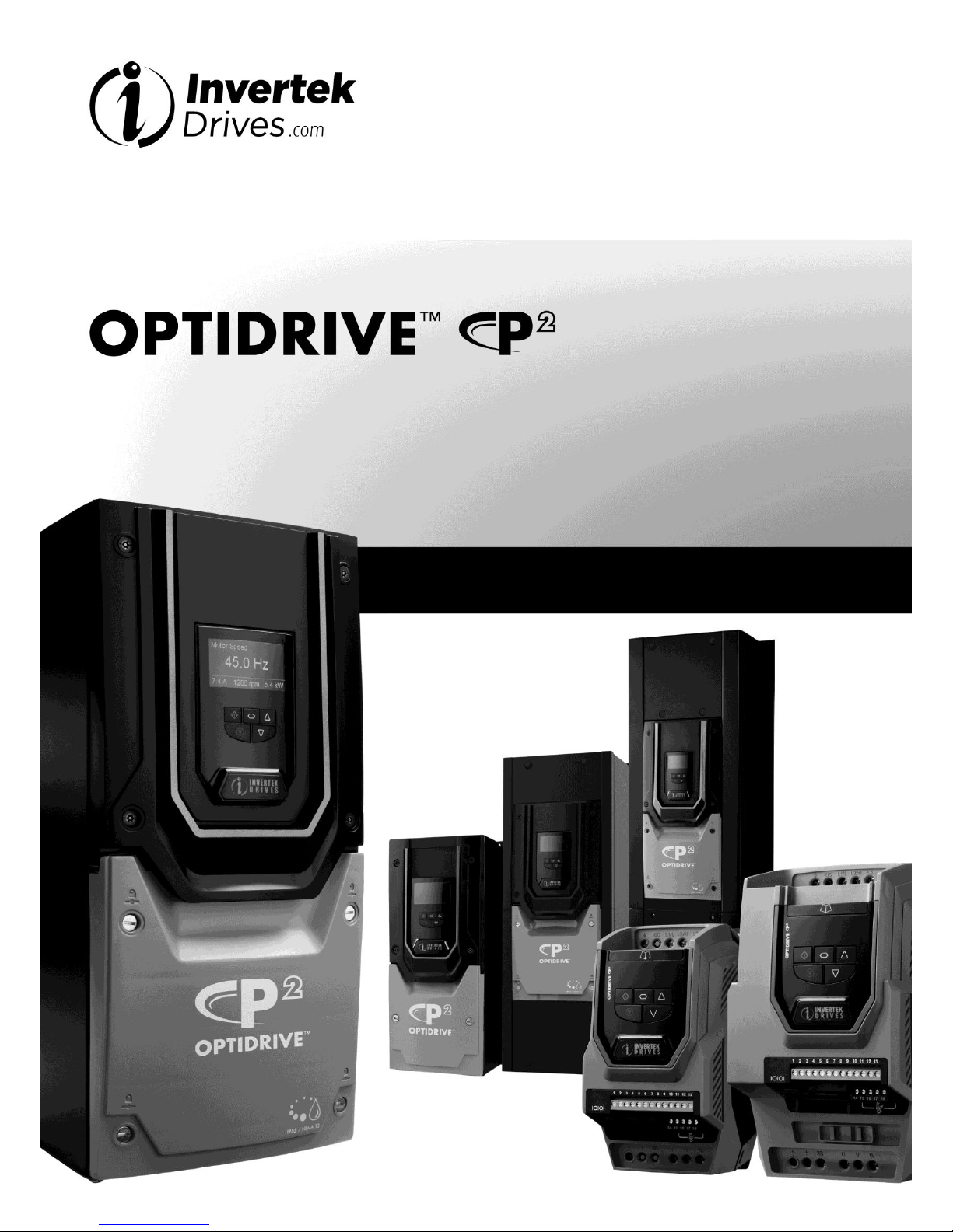
AC Variable Speed Drive
0.75kW – 250kW / 1HP – 350HP
200 – 480 Volt 1 & 3 Phase
Advanced User Guide
Revision 2.00
Page 2

Optidrive P2 Advanced User Guide Rev 2.00
2
www.invertekdrives.com
Optidrive P2 Parameter Set Overview
1
This Document is for use with version 1.30 Firmware.
Advanced User Guide Revision 1.20
Invertek Drives Ltd adopts a policy of continuous improvement and whilst every effort has been made to provide accurate and up to date
information, the information contained in this User Guide should be used for guidance purposes only and does not form the part of any
contract.
Revision History
Revision
Note
1.00
First Release
1.10
Updated to include V1.20 Firmware changes
Added comms info
Added additional technical specification
Updated parameter descriptions
1.20
Major updated to include V2.00 firmware changes
Additional sections added
Extensive revisions to parameter descriptions, ranges, default values and descritpions
Revised Technical data and explanations
iTHD table added
Motor Performance Data Added
Added Standby Consumption
Added 600 Volt data
Added DC Bus Voltage Thresholds
2.00
Updated to reflect V2.00 firmware enhancements
This user guide is intended to provide technical information and explanation of the operation and parameters of the Optidrive P2 product
range. The information contained withn is intended to reflect the latest available firmware functionality at the time of release. This user guide
must be read in conjunction with the Optidrive P2 User Guide included with each product, and in particular, all relevant safety information and
warnings. The information is intended to reflect the product as accurately as possible, however Invertek Drives accepts no liability for
information contained herein.
This document is intended for persons who are already familiar with the installation, mounting, start-up and operation of the equipment and
the hazards involved. The reader should be trained and in the operation of electrical equipment, and heave the necessary authority to
energize, de-energize, clear, ground and tag circuits and equipment in accordance with established safety procedures. In addition, they should
be trained in the proper care and use of protective equipment in accordance with established safety procedures.
Page 3

Optidrive P2 Advanced User Guide Rev 2.00
www.invertekdrives.com
3
Optidrive P2 Parameter Set Overview
1
1. Optidrive P2 Parameter Set Overview .......................................................................................... 4
1.1. About this section ............................................................................................................................................................... 4
1.2. Parameter Structure Overview ........................................................................................................................................... 4
1.3. Parameter Descriptions ...................................................................................................................................................... 5
1.4. Parameter Group 9 – Programmable Logic Functions ...................................................................................................... 22
1.5. Parameter Group 0 – Monitoring Parameters (Read Only) .............................................................................................. 26
1.6. P6-28 Value Selection ....................................................................................................................................................... 29
1.7. Control Terminal Connections .......................................................................................................................................... 30
2. Drive Model Specific Parameter Variations ................................................................................ 34
2.1. Available Effective Switching Frequency Options ............................................................................................................. 34
2.2. V/F Mode Voltage Boost Setting Options ......................................................................................................................... 35
3. Embedded Firmware Functions .................................................................................................. 36
3.1. 24 Hour Time Clock ........................................................................................................................................................... 36
4. Fieldbus Interface Support ......................................................................................................... 37
4.1. Fieldbus Interface Options ................................................................................................................................................ 37
4.2. Fieldbus Support Overview ............................................................................................................................................... 37
4.3. Simple Drive Control ......................................................................................................................................................... 37
4.4. Drive Control Word Definition :- ....................................................................................................................................... 38
4.5. Drive Status Word Definition ............................................................................................................................................ 38
4.6. Parameter Access Overview ............................................................................................................................................. 38
4.7. Parameter Access Tables .................................................................................................................................................. 40
5. Diagnostic and Fault Messages .................................................................................................. 58
6. Rated Temperatures and De-rating curves ................................................................................. 59
6.1. Thermal Management ...................................................................................................................................................... 59
6.2. De-rating Curves Explained ............................................................................................................................................... 59
6.3. Size 2, 200-240V ................................................................................................................................................................ 60
6.4. Size 2, 380-480V ................................................................................................................................................................ 62
6.5. Size 3, 200-240V & 380 – 480V ......................................................................................................................................... 64
6.6. Size 4, 200 – 240V & 380-480V, ........................................................................................................................................ 66
6.7. Size 5, 200 – 240V & 380-480V, ........................................................................................................................................ 67
6.8. Size 6, 200 – 240V & 380-480V, ........................................................................................................................................ 68
6.9. Size 7, 200 – 240V & 380-480V, ........................................................................................................................................ 69
7. Immunity Tests ......................................................................................................................... 70
7.1. Electrostatic Discharge (ESD) ............................................................................................................................................ 70
7.2. Electrical Fast Transient Burst (EFT/B) .............................................................................................................................. 70
7.3. Surge ................................................................................................................................................................................. 70
7.4. Dielectric strength (Flash) ................................................................................................................................................. 70
8. General Technical and Performance Data ................................................................................... 71
8.1. Electrical Data ................................................................................................................................................................... 71
8.2. Input Output Current Ratings ........................................................................................................................................... 71
8.3. Standby Power Consumption............................................................................................................................................ 74
8.4. DC Bus Discharge Time ...................................................................................................................................................... 74
8.5. Earth Leakage Current (Touch Current) ............................................................................................................................ 75
8.6. Digital & Analog I/O .......................................................................................................................................................... 76
8.7. Environmental Data .......................................................................................................................................................... 77
8.8. Response Times ................................................................................................................................................................ 77
8.9. Motor Control Performance ............................................................................................................................................. 77
8.10. Output Current Limit ......................................................................................................................................................... 78
8.11. Under / Over Voltage Trip Levels ...................................................................................................................................... 79
Page 4
Optidrive P2 Advanced User Guide Rev 2.00
4
www.invertekdrives.com
Optidrive P2 Parameter Set Overview
1
1. Optidrive P2 Parameter Set Overview
1.1. About this section
This document provides a list of the available parameters, and a description of their respective functions, for the Optidrive P2.
1.2. Parameter Structure Overview
The parameter set is arranged in Groups according to the following structure
Parameter Group
Range
Name
Access Level
Access Type
Group 0
P0-01 to P0-50
Basic Monitoring
Extended
Read Only
P0-51 to P0-80
Advanced Monitoring
Advanced
Read Only
Group 1
P1-01 to P1-14
Quick Start Menu
Basic
Read / Write
Group 2
P2-01 to P2-40
Extended Parameters
Extended
Read / Write
Group 3
P3-01 to P3-12
PID Controller
Extended
Read / Write
Group 4
P4-01 to P4-12
Motor Control
Extended
Read / Write
Group 5
P5-01 to P5-10
Communications
Extended
Read / Write
Group 6
P6-01 to P6-30
Advanced Functions
Advanced
Read / Write
Group 7
P7-01 to P7-10
Advanced Motor Data
Advanced
Read / Write
Group 8
P8-01 to P8-10
Application Specific Group
Advanced
Read / Write
Group 9
P9-01 to P9-30
Programmable Logic
Advanced
Read / Write
Access to all parameter groups is controlled by setting P1-14 as follows
P1-14 = P2-40 (Factory setting: 101) Allows Extended Parameter Access
P1-14 = P6-30 (Factory Setting: 201) Allows Advanced Parameter Access
Page 5
Optidrive P2 Advanced User Guide Rev 2.00
www.invertekdrives.com
5
Optidrive P2 Parameter Set Overview
1
1.3. Parameter Descriptions
1.3.1. Parameter Group 1 – Basic Parameters
Par.
Name
Minimum
Maximum
Default
Units
P1-01
Maximum Frequency / Speed Limit
P1-02
500.0 / 30000
50.0 (60.0)
Hz / Rpm
Maximum output frequency or motor speed limit – Hz or rpm.
If P1-10 > 0, the value entered / displayed is in Rpm
The value which may be entered by the user is limited by the lower of the following :5 x P1-09 value
P2-24 / 16
P1-02
Minimum Frequency / Speed Limit
0.0
P1-01
0.0
Hz / Rpm
Minimum speed limit – Hz or rpm.
If P1-10 >0, the value entered / displayed is in Rpm
P1-03
Acceleration Ramp Time
See Below
5.0
Seconds
Acceleration ramp time from 0 to base speed (P-1-09) in seconds.
Note
For Optidrive P2 units Frame Sizes 2 and 3, the parameter range is adjustable between 0.00 and 600.0 seconds
For Optidrive P2 units Frame Sizes 4 and above, the parameter range is adjustable between 0.0 and 6000.0 seconds
P1-04
Deceleration Ramp Time
See Below
5.0
Seconds
Deceleration ramp time from base speed (P1-09) to standstill in seconds. When set to zero, fastest possible ramp time without trip is
activated
Note
For Optidrive P2 units Frame Sizes 2 and 3, the parameter range is adjustable between 0.00 and 600.0 seconds
For Optidrive P2 units Frame Sizes 4 and above, the parameter range is adjustable between 0.0 and 6000.0 seconds
P1-05
Stop Mode 0 4 0 -
This parameter has several functions :-
- To enable / disable the brake chopper during deceleration
- To select the stopping mode (Ramp or Coast)
- To enable the AC Flux Braking function
0 : Ramp To Stop. When the enable signal is removed, the drive will ramp to stop, with the rate controlled by P1-04 as described
above. In this mode, the drive brake transistor is disabled.
1 : Coast to Stop. When the enable signal is removed, the drive output is immediately disabled, and the motor will coast (freewheel) to
stop. If the load can continue to rotate due to inertia, and the drive may possibly be re-enabled whilst the motor is still rotating, the
spin start function (P2-26) should be enabled. In this mode, the drive brake transistor is disabled.
2 : Ramp To Stop, Brake Chopper Enabled. When the enable signal is removed, the drive will ramp to stop, with the rate controlled by
P1-04 as described above. The brake chopper is also enabled in this mode.
3 : Coast to Stop, Brake Chopper Enabled. When the enable signal is removed, the drive output is immediately disabled, and the
motor will coast (freewheel) to stop. If the load can continue to rotate due to inertia, and the drive may possibly be re-enabled whilst
the motor is still rotating, the spin start function (P2-26) should be enabled. The drive brake chopper is enabled in this mode, however
it will only activate when required during a change in the drive frequency setpoint, and will not activate when stopping.
4 : AC Flux Braking. AC Flux braking provides improved braking torque during stopping and dceceleration. In this mode, the brake
chopper is disabled, however braking torque is improved.
P1-06
Energy Optimiser
0 1 0
-
Only active when enhanced V/F motor control mode is selected (P4-01 = 2).
0 : Disabled
1 : Enabled. When enabled, the Energy Optimiser attempts to reduce the overall energy consumed by the drive and motor when
operating at constant speeds and light loads. The output voltage applied to the motor is reduced. The Energy Optimiser is intended for
applications where the drive may operate for some periods of time with constant speed and light motor load, whether constant or
variable torque.
P1-07
Motor Rated Voltage
0
See Below
See Below
Volts
This parameter should be set to the rated (nameplate) voltage of the motor (Volts)
The factory default setting of this parameter is drive model dependent as follows :All kw & HP models intended for 200 – 240 volt operation (e.g. ODP-2-x2xxx-xxF4x) : Factory setting = 230 Volts, Maximum 250 Volts
All kW models intended for 380 – 480 volt operation (e.g. ODP-2-x4xxx-3KFxN) : Factory setting = 400 Volts, Maximum 500 Volts
All HP models intended for 380 – 480 volt operation (e.g. ODP-2-x4xxx-3HFxN) : Factory setting = 460 Volts, Maximum 500 Volts
When this parameter is set to the motor nameplate voltage, the output voltage from the drive is controlled automatically and
maintained at the correct level wherever possible regardless of variations in supply voltage or DC Bus Voltage.
When P1-07 = 0, the voltage compensation function of the inverter is disabled. The output voltage applied to the motor will increase
or decrease with changes in the DC Bus voltage.
Note
The RMS output voltage from the inverter can never exceed the incoming supply voltage.
P1-08
Motor Rated Current
-
-
See Below
Amps
This parameter should be set to the rated (nameplate) current of the motor.
The factory default setting of this parameter is the set to the maximum continuously available output current of the drive
Page 6
Optidrive P2 Advanced User Guide Rev 2.00
6
www.invertekdrives.com
Optidrive P2 Parameter Set Overview
1
P1-09
Motor Rated Frequency
10
500
60 (60)
Hz
This parameter should be set to the rated (nameplate) frequency of the motor.
The factory default setting of this parameter is drive model dependent as follows :All kW models (e.g. ODP-2-xxxxx-xKFxx) : Factory setting = 50Hz
All HP models (e.g. ODP-2-xxxxx-xHFxx) : Factory setting = 60 Hz
P1-10
Motor Rated Speed
0
30000
0
Rpm
This parameter can optionally be set to the rated (nameplate) rpm of the motor. When set to the default value of zero, all speed
related parameters are displayed in Hz, and the slip compensation for the motor is disabled. Entering the value from the motor
nameplate enables the slip compensation function, and the Optidrive display will now show motor speed in estimated rpm. All speed
related parameters, such as Minimum and Maximum Speed, Preset Speeds etc. will also be displayed in Rpm.
Note
When the drive is operated with the optional Encoder Feedback Interface, this parameter must be set to the correct nameplate Rpm of
the connected motor.
P1-11
V/F Mode Voltage Boost
0.0
See Below
See Below
%
This parameter is effective only when operating in V/F Mode (P4-01 = 2).
Voltage boost is used to increase the applied motor voltage at low output frequencies, in order to improve low speed and starting
torque. Excessive voltage boost levels may result in increased motor current and temperature, and force ventilation of the motor may
be required.
An automatic setting () is also possible, whereby the Optidrive will automatically adjust this parameter based on the motor
parameters measured during an autotune.
The factory default and maximum limit for this parameter are drive model dependent, refer to section 0 for further information
P1-12
Primary Command Source Mode
0 6 0
-
0 : Terminal Control. The drive responds directly to signals applied to the control terminals.
1 : Uni-directional Keypad Control
1)2)3)
The drive can be controlled in the forward direction only using an external or remote Keypad
2 : Bi-directional Keypad Control 4) The drive can be controlled in the forward and reverse directions using an external or remote
Keypad. Pressing the keypad START button toggles between forward and reverse.
3 : PID Control. The output frequency is controlled by the internal PID controller.
4 : Fieldbus Control. Control via Modbus RTU if no fieldbus interface option is present, otherwise control is from the fieldbus option
module interface
5 : Slave Mode. The drive acts as a Slave to a connected Optidrive operating in Master Mode
6 : CAN bus Control. Control via CAN bus connected to the RJ45 serial interface connector
Note
1) When operating with P1-12 = 1 or 2, the drive will not operate the motor unless the enable signal is present (e.g. Control
Terminals 1 & 2 are linked together), regardless of the setting of P2-37. If P2-37 > = 4, the drive will start when the link is
closed between terminals 1 & 2, and will not require the keypad start button to be pressed. If P2-37 < 4, the Start Button
must be pressed to operate the drive after the link is closed between terminals 1 & 2.
2) The motor direction of rotation may still be controlled by signals applied to the digital inputs, dependent on the setting of
P1-13, e.g. the motor can still be controlled in both forward and reverse directions if required, however the Reverse direction
function of the Start key is disabled.
3) When operating in this mode and utilising a setting of P1-13 that allows preset speeds to be also selected from the drive
digital inputs, setting a negative value in the preset speed parameter will cause the drive to reverse the direction of motor
rotation.
4) When P1-12 = 2, the direction of motor rotation may be changed by any of the following :-
a. Pressing the keypad Start button
b. A Reverse Digital Input, dependent on the setting of P1-13
c. Selecting a Negative Preset Speed
It is important to ensure that a combination of the above used incorrectly does not result in unexpected operation.
P1-13
Digital Inputs Function Select
0
21 1 -
Defines the function of the digital inputs depending on the control mode setting in
P1-12. See section 1.7 on page 30 for further information.
P1-14
Extended Menu Access Code
0
30000 0 -
Parameter Access Control. The following settings are applicable :
P1-14 = P2-40 (Factory Setting = 101) : Allows access to Parameter Groups 0 – 5
P1-14 = P6-30 (Factory Setting = 201) : Allows Access to all drive parameters
Page 7
Optidrive P2 Advanced User Guide Rev 2.00
www.invertekdrives.com
7
Optidrive P2 Parameter Set Overview
1
1.3.2. Parameter Group 2 - Extended parameters
Par.
Name
Minimum
Maximum
Default
Units
P2-01
Preset / Jog Frequency / Speed 1
-P1-01
P1-01
5.0
Hz / Rpm
P2-02
Preset / Jog Frequency / Speed 2
-P1-01
P1-01
10.0
Hz / Rpm
P2-03
Preset / Jog Frequency / Speed 3
-P1-01
P1-01
25.0
Hz / Rpm
P2-04
Preset / Jog Frequency / Speed 4
-P1-01
P1-01
50.0 (60.0)
Hz / Rpm
P2-05
Preset / Jog Frequency / Speed 5
-P1-01
P1-01
0.0
Hz / Rpm
P2-06
Preset / Jog Frequency / Speed 6
-P1-01
P1-01
0.0
Hz / Rpm
P2-07
Preset / Jog Frequency / Speed 7
-P1-01
P1-01
0.0
Hz / Rpm
P2-08
Preset / Jog Frequency / Speed 8
-P1-01
P1-01
0.0
Hz / Rpm
Preset Speeds / Frequencies which may be selected by the digital inputs dependent on the setting of P1-13 (Refer to section 1.7 on
page 30).
If P1-10 = 0, the values are entered as Hz. If P1-10 > 0, the values are entered as Rpm.
Setting a negative value will reverse the direction of motor rotation.
P2-09
Skip Frequency Centre Point
0.0
P1-01
0.0
Hz
P2-10
Skip Frequency Band Width
0.0
P1-01
0.0
Hz
The Skip Frequency function is used to avoid the Optidrive operating at a certain output frequency, for example at a frequency which
causes mechanical resonance in a particular machine. Parameter P2-09 defines the centre point of the skip frequency band, and is
used conjunction with P2-10. The Optidrive output frequency will ramp through the defined band at the rates set by the acceleration
and deceleration ramps currently in use, and will not hold any output frequency within the defined band. If the frequency reference
applied to the drive is within the band, the Optidrive output frequency will remain at the upper or lower limit of the band.
P2-11
Analog Output 1 (Terminal 8) Function Select
0
12 8 -
Digital Output Mode. Logic 1 = +24V DC (20mA Max)
0 : Drive Enabled (Running). Logic 1 when the Optidrive is enabled (Running)
1 : Drive Healthy. Logic 1 When no Fault condition exists on the drive and the STO input is closed.
2 : At Target Frequency (Speed). Logic 1 when the output frequency matches the setpoint frequency and the drive is enabled.
Hysterisis is applied, defined by P6-04.
3 : Output Frequency > 0.0. Logic 1 when the motor runs above zero speed. Hysterisis is applied, defined by P6-04.
4 : Output Frequency >= Limit. Logic 1 when the motor speed exceeds the adjustable limit
5 : Output Current >= Limit. Logic 1 when the motor current exceeds the adjustable limit
6 : Motor Torque >= Limit. Logic when the motor torque exceeds the adjustable limit
7 : Analog Input 2 Signal Level >= Limit. Logic when the signal applied to the Analog Input 2 exceeds the adjustable limit
Note : When using settings 4 – 7, parameters P2-16 and P2-17 must be used together to control the behaviour. The output will switch
to Logic 1 when the selected signal exceeds the value programmed in P2-16, and return to Logic 0 when the signal falls below the value
programmed in P2-17.
Analog Output Mode
8 : Output Frequency (Motor Speed). 0 to P-01
9 : Output (Motor) Current. 0 to 200% of P1-08
10 : Motor Torque. 0 to 200% of motor rated torque
11 : Output (Motor) Power. 0 to 200% of drive rated power
12 : PID Controller Output. 0 – 100% of PID Controller Output
P2-12
Analog Output 1 (Terminal 8) Format
-
-
-
= 0 to10V.
= 10 to 0V,
= 0 to 20mA
= 20 to 0mA
= 4 to 20mA
= 20 to 4mA
Page 8
Optidrive P2 Advanced User Guide Rev 2.00
8
www.invertekdrives.com
Optidrive P2 Parameter Set Overview
1
Par.
Name
Minimum
Maximum
Default
Units
P2-13
Analog Output 2 (Terminal 11) Function Select
0
12 9 -
Digital Output Mode. Logic 1 = +24V DC
0 : Drive Enabled (Running). Logic 1 when the Optidrive is enabled (Running)
1 : Drive Healthy. Logic 1 When no Fault condition exists on the drive
2 : At Target Frequency (Speed). Logic 1 when the output frequency matches the setpoint frequency. Hysterisis is applied, defined by
P6-04.
3 : Output Frequency > 0.0. Logic 1 when the motor runs above zero speed. Hysterisis is applied, defined by P6-04.
4 : Output Frequency >= Limit. Logic 1 when the motor speed exceeds the adjustable limit
5 : Output Current >= Limit. Logic 1 when the motor current exceeds the adjustable limit
6 : Output Toque >= Limit. Logic when the motor torque exceeds the adjustable limit
7 : Analog Input 2 Signal Level >= Limit. Logic when the signal applied to the Analog Input 2 exceeds the adjustable limit
Note : When using settings 4 – 7, parameters P2-16 and P2-17 must be used together to control the behaviour. The output will switch
to Logic 1 when the selected signal exceeds the value programmed in P2-16, and return to Logic 0 when the signal falls below the value
programmed in P2-17.
Analog Output Mode
8 : Output Frequency (Motor Speed). 0 to P-01
9 : Output (Motor) Current. 0 to 200% of P1-08
10 : Motor Torque. 0 to 200% of motor rated torque
11 : Output (Motor) Power. 0 to 200% of drive rated power
12 : PID Controller Output. 0 – 100% of PID Controller Output
P2-14
Analog Output 2 (Terminal 11) Format
-
-
-
= 0 to10V.
= 10 to 0V,
= 0 to 20mA
= 20to 0mA
= 4 to 20mA
= 20 to 4mA
P2-15
User Relay 1 Output (Terminals 14, 15 & 16) Function
select
0
14 1 -
Selects the function assigned to Relay Output 1. The relay has three output terminals, Logic 1 indicates the relay is active, and
therefore terminals 14 and 15 will be closed together.
0 : Drive Enabled (Running). Logic 1 when the motor is enabled
1 : Drive Healthy. Logic 1 when power is applied to the drive and no fault exists
2 : At Target Frequency (Speed). Logic 1 when the output frequency matches the setpoint frequency. Hysterisis is applied, defined by
P6-04.
3 : Output Frequency > 0.0 Hz. Logic 1 when the drive output frequency to the motor is exceeds 0.0Hz. Hysterisis is applied, defined by
P6-04.
4 : Output Frequency >= Limit. Logic 1 when the motor speed exceeds the adjustable limit
5 : Output Current >= Limit. Logic 1 when the motor current exceeds the adjustable limit
6 : Output Torque >= Limit. Logic 1 when the motor torque exceeds the adjustable limit
7 : Analog Input 2 Signal Level >= Limit. 1 Logic when the signal applied to the Analog Input 2 exceeds the adjustable limit
8 : No Function
9 : No Function
10 : Service Due. Logic 1 when the user settable maintenance time (P6-24) has expired. This allows the user to set a service interval
time, for example in the even where a machine requires a defiend service time interval for maintenance, the drive can provide visual
indication of the maintenance interval.
11 : Drive Ready to Run. Defined as not in inhibit mode, hardware enable present, not in mains loss condition and no trip.
12 : Drive Tripped. Logic 1 when the drive has tripped and the display shows a fault.
13 : STO Status. Logic 1 when the STO inputs are present, and the drive is not in inhibit state
Note : When using settings 4 – 7, parameters P2-16 and P2-17 must be used together to control the behaviour. The output will switch
to Logic 1 when the selected signal exceeds the value programmed in P2-16, and return to Logic 0 when the signal falls below the value
programmed in P2-17.
14 : PID Error >= Limit. Logic 1 when the PID Error exceeds the adjustable threshold
P2-16
Adjustable Threshold 1 Upper Limit (Analog Output 1 /
Relay Output 1)
P2-17
200.0
100.0
%
P2-17
Adjustable Threshold 1 Lower Limit (Analog Output 1 /
Relay Output 1)
0.0
P2-16
0.0
%
Used in conjunction with some settings of Parameters P2-11 & P2-15.
Page 9
Optidrive P2 Advanced User Guide Rev 2.00
www.invertekdrives.com
9
Optidrive P2 Parameter Set Overview
1
Par.
Name
Minimum
Maximum
Default
Units
P2-18
User Relay 2 Output (Terminals 17 & 18) Function select
0
14 0 -
Selects the function assigned to Relay Output 2. The relay has two output terminals, Logic 1 indicates the relay is active, and therefore
terminals 17 and 18 will be linked together.
0 : Drive Enabled (Running). Logic 1 when the motor is enabled
1 : Drive Healthy. Logic 1 when power is applied to the drive and no fault exists
2 : At Target Frequency (Speed). Logic 1 when the output frequency matches the setpoint frequency. Hysterisis is applied, defined by
P6-04.
3 : Output Frequency > 0.0 Hz. Logic 1 when the drive output frequency to the motor is exceeds 0.0Hz. Hysterisis is applied, defined by
P6-04.
4 : Output Frequency >= Limit. Logic 1 when the motor speed exceeds the adjustable limit
5 : Output Current >= Limit. Logic 1 when the motor current exceeds the adjustable limit
6 : Output Torque >= Limit. Logic 1 when the motor torque exceeds the adjustable limit
7 : Analog Input 2 Signal Level >= Limit. 1 Logic when the signal applied to the Analog Input 2 exceeds the adjustable limit
8 : Hoist Brake Control. When P2-18 = 8, the Optidrive is set to ‘Hoist Mode Operation’, and output relay 2 must be used to control the
motor holding brake.
9 : No Function
10 : Service Due. Logic 1 when the user settable maintenance time (P6-24) has expired. This allows the user to set a service interval
time, for example in the even where a machine requires a defiend service time interval for maintenance, the drive can provide visual
indication of the maintenance interval.
11 : Drive Ready to Run. Defined as not in inhibit mode, hardware enable present, not in mains loss condition and no trip.
12 : Drive Tripped. Logic 1 when the drive has tripped and the display shows a fault.
13 : STO Status. Logic 1 when the STO inputs are present, and the drive is not in inhibit state
Note : When using settings 4 – 7, parameters P2-19 and P2-20 must be used together to control the behaviour. The output will switch
to Logic 1 when the selected signal exceeds the value programmed in P2-19, and return to Logic 0 when the signal falls below the value
programmed in P2-20.
14 : PID Error >= Limit. Logic 1 when the PID Error exceeds the adjustable threshold
P2-19
Adjustable Threshold 1 Upper Limit (Analog Output 2 /
Relay Output 2)
P2-20
200.0
100.0
%
P2-20
Adjustable Threshold 1 Lower Limit (Analog Output 2 /
Relay Output 2)
0.0
P2-19
0.0
%
Used in conjunction with some settings of Parameters P2-13 & P2-18.
P2-21
Display Scaling Factor
-30.000
30.000
0.000
-
P2-22
Display Scaling Source
0 3 0
-
P2-21 & P2-22 allow the user to program the Optidrive to display an alternative output unit scaled from an existing parameter, e.g. to
display conveyer speed in metres per second based on the output frequency. This function is disabled if P2-21 is set to 0.
If P2-21 is set >0, the variable selected in P2-22 is multiplied by the factor entered in P2-21, and can be displayed whilst the drive is
running. The display will show a ‘’ on the left hand side to indicate the customer scaled units.
P2-22 Setting Options :0 : Motor Speed
1 : Motor Current
2 : Analog Input 2
3 : P0-80 Value
P2-23
Zero Speed Holding Time
0.0
60.0
0.2
Seconds
Determines the time for which the drive output frequency is held at zero when stopping, before the drive output is disabled. This can
be utilised to ensure the motor has come to a complete standstill before the drive switches off, or to allow time for a holding brake to
engage. It is not intended to provide a continuous output holding torque for prolonged periods.
When operating in V/F mode, the output voltage and hence current will be dependent on the setting of P1-11.
When operating in Vector Mode, the output voltage and current are automatically controlled by the vector algorithm.
P2-24
Effective Switching Frequency
See Below
kHz
Effective power stage switching frequency. The range of settings available and factory default parameter setting depend on the drive
power and voltage rating, refer to section 2.1. Higher frequencies reduce the audible ‘ringing’ noise from the motor, and improve the
output current waveform, at the expense of increased drive heat losses.
P2-25
Fast Deceleration Ramp Time (Fast Stop)
0.00
240.0
0.00
Seconds
This parameter allows an alternative deceleration ramp down time to be programmed into the Optidrive, which can be selected by
digital inputs (dependent on the setting of P1-13) or selected automatically in the case of a mains power loss if P2-38 = 2.
When set to 0.00, the drive output will be immediately disabled, and the load will coast to stop.
Page 10
Optidrive P2 Advanced User Guide Rev 2.00
10
www.invertekdrives.com
Optidrive P2 Parameter Set Overview
1
Par.
Name
Minimum
Maximum
Default
Units
P2-26
Spin Start Enable
0 2 0
-
0 : Disabled
1 : Enabled. When enabled, on start up the drive will attempt to determine if the motor is already rotating, and will begin to control
the motor from its current speed. This can be useful for high inertia loads, or fans which may spin due to air movement even when the
drive is not enabled. A short delay may be observed when starting motors which are not already rotating. The spin start will detect the
motor direction of rotation, and will automatically operate and control the motor from that point, including reversing the direction of
motor rotation where required.
2 : Enabled on Fault, Brown Out or Coast. As setting one, however the Spin Start function activates only following any event that may
have caused an uncontrolled stop of the motor previously.
Note
The Spin Start function cannot detect motors which are rotating at speeds above the maximum speed limit parameter (P1-01) setting
of the drive.
P2-27
Standby Mode Timer
0.0
250.0
0.0
Seconds
This parameter defines time period, whereby if the drive operates continuously at minimum frequency / speed for at least the set time
period, the Optidrive output will be disabled, and the display will show . The function is disabled if P2-27 = 0.0.
If the speed demand rises above minimum, the drive will immediately restart automatically.
P2-28
Slave Speed Scaling Control
0 3 0
-
Active in Slave mode (P1-12=5) only. The Master speed reference can be multiplied by a preset scaling factor or adjusted using an
analog trim or offset.
0 : Disabled. No scaling or offset is applied.
1 : Actual Speed = Master Speed x P2-29
2 : Actual Speed = (Master Speed x P2-29) + Analog Input 1 Reference. Analog Input 1 Full Scale 100.0% = P1-01
3 : Actual Speed = (Master Speed x P2-29) x Analog Input 1 Reference. Analog input 1 full scale = 200.0% (unsigned/absolute)
P2-29
Slave Speed Scaling Factor
-500.0
500.0
100.0
%
Used in conjunction with P2-28.
P2-30
Analog Input 1 (Terminal 6) Format
-
-
-
= 0 to 10 Volt Signal (Uni-polar)
= 10 to 0 Volt Signal (Uni-polar)
= -10 to +10 Volt Signal (Bi-polar)
= 0 to 20mA Signal
= 4 to 20mA Signal, the Optidrive will trip and show the fault code if the signal level falls below 3mA
= 4 to 20mA Signal. In the event that the signal falls below 3mA, the Optidrive will ramp operate at Preset Speed 4.
= 20 to 4mA Signal, the Optidrive will trip and show the fault code if the signal level falls below 3mA
= 20 to 4mA Signal. In the event that the signal falls below 3mA, the Optidrive will ramp operate at Preset Speed 4.
P2-31
Analog Input 1 Scaling
0.0
2000.0
100.0
%
Scales the analog input by this factor. See parameter description below for further information.
P2-32
Analog Input 1 Offset
-500.0
500.0
0.0
%
Sets an offset, as a percentage of the full scale range of the input, which is applied to the analog input signal.
Analog Input Scaling and Offset are applied to the Analog Input Signal as follows :Result (%) = (Analog Input Level (%) – Analog Input Offset (%)) x Analog Input Scaling (%)
The resultant value for Analog Input 1 can be displayed in P0-01.
E.g. If the analog Input Signal format is 0 – 10 Volts, Offset = 20.0%, Scaling = 50.0%
An analog input signal level of 7 Volts gives the following result :Analog Input Level (%) = 7 / 10 = 70.0%
Result = (70.0 – 20.0)% X 50.0%) = 25.0%
P2-33
Analog Input 2 (Terminal 10) Format
-
-
-
= 0 to 10 Volt Signal (Uni-polar)
= 10 to 0 Volt Signal (Uni-polar)
= Motor PTC Thermistor Input. The drive will trip if the resistance is greater than 2.5kΩ
= 0 to 20mA Signal
= 4 to 20mA Signal, the Optidrive will trip and show the fault code if the signal level falls below 3mA
= 4 to 20mA Signal, the Optidrive will ramp to stop if the signal level falls below 3mA
= 20 to 4mA Signal, the Optidrive will trip and show the fault code if the signal level falls below 3mA
= 20 to 4mA Signal, the Optidrive will ramp to stop if the signal level falls below 3mA
P2-34
Analog Input 2 Scaling
0.0
2000.0
100.0
%
Scales the analog input by this factor. See parameter description below for further information.
P2-35
Analog Input 2 Offset
-500.0
500.0
0.0
%
Sets an offset, as a percentage of the full scale range of the input, which is applied to the analog input signal
Analog Input Scaling and Offset are applied to the Analog Input Signal as follows :Result (%) = (Analog Input Level (%) – Analog Input Offset (%)) x Analog Input Scaling (%)
The resultant value for Analog Input 2 can be displayed in P0-02.
E.g. If the analog Input Signal format is 0 – 10 Volts, Offset = 20.0%, Scaling = 50.0%
An analog input signal level of 7 Volts gives the following result :Analog Input Level (%) = 7 / 10 = 70.0%
Result = (70.0 – 20.0)% X 50.0%) = 25.0%
Page 11
Optidrive P2 Advanced User Guide Rev 2.00
www.invertekdrives.com
11
Optidrive P2 Parameter Set Overview
1
Par.
Name
Minimum
Maximum
Default
Units
P2-36
Start Mode Select / Automatic Restart
-
-
-
Defines the behaviour of the drive relating to the enable digital input and also configures the Automatic Restart function.
: Following Power on or reset, the drive will not start if Digital Input 1 remains closed. The Input must be closed after a power
on or reset to start the drive (e.g. Edge Triggered).
: Following a Power On or Reset, the drive will automatically start if Digital Input 1 is closed before power on.
to : Following a trip, the drive will make up to 5 attempts to restart at intervals defined by P6-03 (default 20 seconds).
The drive must be powered down or reset manually to reset the counter. The numbers of restart attempts are counted, and if the
drive fails to start on the final attempt, the drive will fault with, and will require the user to manually reset the fault.
P2-37
Keypad / Fieldbus Starting Control
0 7 1
-
This parameter controls the starting behaviour of the drive when operating in Keypad Mode or Fieldbus Mode (selected by P1-12).
Settings 0 to 3 are active in Keypad Mode only (P1-12 = 1 or 2), and define the speed at which the drive will initially operate following
the pressing of the keypad Start button.
0 : Minimum Speed, Keypad Start. Following a stop and restart, the drive will always initially run at the minimum speed set in P1-02.
This applies even if the drive is re-enabled whilst still decelerating the motor from the previous stop command.
1 : Previous Operating Speed, Keypad Start. Following a stop and restart, the drive will return to the last keypad setpoint speed used
prior to stopping.
2 : Current Running Speed. Where the Optidrive is configured for multiple speed references, when switched to keypad mode by a
digital input, the drive will continue to operate at the last operating speed. This setting can be used for ‘Bumpless’ changeover
between automatic and manual operating modes of the drive, e.g. typically Hand / Auto control or Local / Remote control.
3 : Preset Speed 8, Keypad Start. Following a stop and restart, the Optidrive will always initially run at Preset Speed 8 (P2-08)
4 : Minimum Speed, Terminal Start. Following a stop and restart, the drive will always initially run at the minimum speed P1-02. The
drive starting is controlled from the digital inputs, based on the setting of P1-13.
5 : Previous Operating Speed, Terminal Start. Following a stop and restart, the drive will return to the last keypad setpoint speed used
prior to stopping. The drive starting is controlled from the digital inputs, based on the setting of P1-13.
6 : Current Running Speed, Terminal Start. Where the Optidrive is configured for multiple speed references (typically Hand / Auto
control or Local / Remote control), when switched to keypad mode by a digital input, the drive will continue to operate at the last
operating speed. The drive starting is controlled from the digital inputs, based on the setting of P1-13.
7 : Preset Speed 8, Terminal Start. Following a stop and restart, the Optidrive will always initially run at Preset Speed 8 (P2-08). The
drive starting is controlled from the digital inputs, based on the setting of P1-13.
P2-38
Mains Loss Ride Through / Stop Control
0 3 0
-
Controls the behaviour of the drive in response to a loss of mains power supply whilst the drive is enabled.
0 : Mains Loss Ride Through. The Optidrive will attempt to continue operating by recovering energy from the motor and connected
load. Providing that the mains loss period is short (e.g. a ‘Brown Out’), the drive enable control remains applied and that sufficient
energy can be recovered before the drive control electronics power off, the drive will automatically maintain motor operation (with
reduced output speed depending on the load), and recover back to the normal operating point on return of mains power.
Where the mains power supply is lost for a longer period (e.g. a ‘Black Out’) and there is insufficient kinetic energy available from the
load to maintain the drive electronic power supply, the restarting behaviour of the drive on return of the power supply will be
controlled by P2-36.
1 : Coast To Stop. On a loss of mains power supply, either ‘Brown Out’ or ‘Black Out’, the Optidrive will immediately disable the output
to the motor, allowing the load to coast or free wheel. When using this setting with high inertia loads, which may still be rotating when
the mains power returns, the Spin Start function (P2-26) should be enabled.
2 : Fast Ramp To Stop. On a loss of mains power supply, either ‘Brown Out’ or ‘Black Out’, the Optidrive will attempt to decelerate the
load to standstill at the rate programmed in the Fast deceleration time (P2-25), by recovering energy from the load. As the speed of
the load approaches zero, if the mains power supply has not been restored, the drive control electronics may power down shortly
before the load reaches a complete standstill. If the power returns whilst the drive is still decelerating the load, and the run signal is
maintained, the drive will resume operation and accelerate the load back to the operating speed.
3 : DC Power Supply. This option should be used where the drive is powered via the DC Bus terminals only, and no AC supply is
present.
P2-39
Parameter Access Lock
0 1 0
-
0 : Unlocked. All parameters can be accessed and changed
1 : Locked. Parameter values can be displayed, but cannot be changed
P2-40
Extended Parameter Access Code Definition
0
9999
101
-
Defines the access code which must be entered in P1-14 to access parameter groups above Group 1.
Page 12
Optidrive P2 Advanced User Guide Rev 2.00
12
www.invertekdrives.com
Optidrive P2 Parameter Set Overview
1
1.3.3. Parameter Group 3 – PID Control
Par.
Name
Minimum
Maximum
Default
Units
P3-01
PID Proportional Gain
0.1
30.0
1.0
-
PID Controller Proportional Gain. Higher values provide a greater change in the drive output frequency in response to small changes in
the feedback signal. Too high a value can cause instability
P3-02
PID Integral Time Constant
0.0
30.0
1.0
Seconds
PID Controller Integral Time. Larger values provide a more damped response for systems where the overall process responds slowly
P3-03
PID Differential Time Constant
0.00
1.00
0.00
Seconds
PID Differential Time Constant
P3-04
PID Operating Mode
0 1 0
-
0 : Direct Operation. Use this mode if an increase in the motor speed should result in an increase in the feedback signal
1 : Inverse Operation. Use this mode if an increase in the motor speed should result in a decrease in the feedback signal
P3-05
PID Reference (Setpoint) Source Select
0 2 0
-
Selects the source for the PID Reference / Setpoint
0 : Digital Preset Setpoint. P3-06 is used
1 : Analog Input 1 Setpoint
2 : Analog Input 2 Setpoint
P3-06
PID Digital Reference (Setpoint)
0.0
100.0
0.0
%
When P3-05 = 0, this parameter sets the preset digital reference (setpoint) used for the PID Controller
P3-07
PID Controller Output Upper Limit
P3-08
100.0
100.0
%
Limits the maximum value output from the PID controller
P3-08
PID Controller Output Lower Limit
0.0
P3-07
0.0
%
Limits the minimum output from the PID controller
P3-09
PID Output Limit Control
0 3 0
-
0 : Digital Output Limits. The output range of the PID controller is limited by the values of P3-07 & P3-08
1 : Analog Input 1 Provides a Variable Upper Limit. The output range of the PID controller is limited by the values of P3-08 & the signal
applied to Analog Input 1
2 : Analog Input 1 Provides a Variable Lower Limit. The output range of the PID controller is limited by the signal applied to Analog
Input 1 & the value of P3-07
3 : PID output Added to Analog Input 1 Value. The output value from the PID Controller is added to the speed reference applied to the
Analog Input 1
P3-10
PID Feedback Signal Source Select
0 5 0
-
0 : Analog Input 2
1 : Analog Input 1
2 : Motor Current. The feedback value is scaled such that 100.0% = P1-08
3 : DC bus voltage. The feedback is scaled such that 100.0% = 1000 Volts
4 : Differential : Analog input 1 – Analog input 2. PID Feedback = P0-01 – P0-02, limited to 0.0 minimum value
5 : Largest Value : Analog Input 1 or Analog Input 2.
P3-11
Maximum PID Error to Enable Ramps
0.0
25.0
0.0
%
Defines a threshold PID error level, whereby if the difference between the setpoint and feedback values is less than the set threshold,
the internal ramp times of the drive are disabled. Where a greater PID error exists, the ramp times are enabled to limit the rate of
change of motor speed on large PID errors, and react quickly to small errors.
Setting to 0.0 means that the drive ramps are always enabled. This parameter is intended to allow the user to disable the drive internal
ramps where a fast reaction to the PID control is required, however by only disabling the ramps when a small PID error exists, the risk
of possible over current or over voltage trips being generated are reduced.
P3-12
PID Feedback Value Display Scaling Factor
0.000
50.000
0.000
-
Applies a scaling factor to the displayed PID feedback, allowing the user to display the actual signal level from a transducer, e.g. 0 – 10
Bar etc. The value is displayed with an ‘r’ prefix, to one decimal place.
P3-13
PID Error Wake Up Level
0.0
100.0
5.0
%
Sets a programmable level whereby if the drive enters standby motor whilst operating under PID control, the difference between the
setpoint and the selected feedback signal increase beyond this threshold before the drive will return to normal operation.
P3-18
PID Reset Control
0 1 0
-
This parameter is used to control the reset behaviour of the PID controller.
0 : Continuous Run. In this mode, the PID controller operates continuously, regardless of the operating state of the drive. This can
result in the output of the PID controller integrating up to the maximum limit prior to the drive being enabled.
1 : Reset On Disable. In this mode, the PID controller output is reset to zero when the drive is disabled, and restarts when the drive is
enabled.
Page 13
Optidrive P2 Advanced User Guide Rev 2.00
www.invertekdrives.com
13
Optidrive P2 Parameter Set Overview
1
1.3.4. Parameter Group 4 – High Performance Motor Control
Par.
Name
Minimum
Maximum
Default
Units
Incorrect adjustment of parameters in menu group 4 can cause unexpected behaviour of the motor and any connected machinery.
It is recommended that these parameters are only adjusted by experienced users.
P4-01
Motor Control Mode
0 6 2
-
Selects the motor control method. An autotune must be performed if setting 0 or 1 is used.
0 : IM Motor Vector Speed Control with Torque Limit. Suitable for use with AC induction motors, Vector Speed Control Mode provides
greater low speed torque, and improved motor speed regulation with respect to load changes. The drive primarily operates in Speed
Control Mode, where the motor speed is controlled by the chosen setpoint source. When the output torque level approaches the
maximum limit, the drive will reduce the motor speed in attempt to reduce the torque demand required. The factory parameter
settings allow a fixed maximum torque limit of 200% set in parameter P4-07. Alternative torque limit settings and variable torque
limits may be selected using P4-06 and P4-07.
1 : IM Motor Vector Torque Control with Speed Limit. Suitable for use with AC induction motors, when Vector Torque Control Mode is
selected, the drive primarily operates in Torque Control Mode, where the motor attempt to generate the output torque level required
by the torque setpoint source. This will generally cause the motor to accelerate in speed. When the output speed approaches the
maximum limit, the drive will not accelerate beyond this point. The speed limit source should be selected by using P1-12 and P1-13,
and the torque reference source should be set in P4-06.
2 : Speed Control (Enhanced V/F). This operating mode is suitable for general purpose operation of standard induction motors.
3 : PM Motor Vector Speed Control. Equivalent to setting 0, but intended for operation of Permanent Magnet motors.
4 : PM Motor Vector Torque Control. Equivalent to setting 1, but intended for operation of Permanent Magnet motors.
5 : BLDC Motor Speed Control. For operation of Brushless DC Motors.
6 : SynRel Motor Speed Control. For operation of Synchronous Reluctance Motors.
Note
Options 3 to 6 are only available when Advanced Parameter Access has been set.
P4-02
Motor Parameter Auto-tune Enable
0 1 0
-
When set to 1, the drive immediately carries out an autotune to measure the motor parameters for optimum control and efficiency.
Following completion of the autotune, the parameter automatically returns to 0.
Note
All motor nameplate data should be programmed into the drive, e.g. P1-07, P1-08, P1-09 and P4-05 prior to starting the autotune
Whilst the autotune does not require the motor to rotate, it may still cause some movement of the motor shaft,
thereby it is important to ensure that the motor and load are safe to operate prior to starting the autotune.
The autotune does not require the load to be removed from the motor, however the motor brake should be
released providing it is safe to do so.
P4-03
Vector Speed Controller Proportional Gain
0.1
400.0
50.0
%
Sets the proportional gain value for the speed controller when operating in Vector Speed or Vector Torque motor control modes (P401 = 0 or 1). Higher values provide better output frequency regulation and response. Too high a value can cause the speed to
overshoot the setpoint during acceleration, and may also cause speed instability and possibly over current trips. For applications
requiring best possible performance, the value should be adjusted to suit the connected load by gradually increasing the value and
monitoring the actual output speed of the load until the required dynamic behaviour is achieved with little or no overshoot of the
target speed during acceleration and deceleration.
In general, higher friction loads can tolerate higher values of proportional gain, and high inertia, low friction loads may require the gain
to be reduced.
P4-04
Vector Speed Controller Integral Time Constant
0.000
2.000
0.100
Seconds
Sets the integral time for the speed controller. Smaller values provide a faster response in reaction to motor load changes, at the risk
of introducing instability. For best dynamic performance, the value should be adjusted to suit the connected load.
P4-05
Motor Power Factor Cos Ø
0.00
0.99 - -
When operating in Vector Speed or Vector Torque motor control modes, this parameter must be set to the motor nameplate power
factor before an autotune is carried out.
P4-06
Torque Control Reference / Limit Source
0 5 0
-
When P4-01 = 0, this parameter defines the source for the maximum output torque limit.
When P4-01 = 1, this parameter defines the source for the torque reference (setpoint).
0 : Fixed Digital. The torque controller reference / limit is set in P4-07
1 : Analog Input 1. The output torque is controlled based on the signal applied to Analog Input 1, whereby 100% input signal level will
result in the drive output torque being limited by the value set in P4-07.
2 : Analog Input 2. The output torque is controlled based on the signal applied to Analog Input 2, whereby 100% input signal level will
result in the drive output torque being limited by the value set in P4-07.
3 : Fieldbus. The output torque is controlled based on the signal from the communications Fieldbus, whereby 100% input signal level
will result in the motor output torque being set or limited to motor rated torque.
4 : Master. The output torque is controlled based on the signal from the Master when operating in Master / Slave mode.
5 : PID Controller Output. The output torque is controlled based on the output of the PID controller, whereby 100% input signal level
will result in the drive output torque being limited by the value set in P4-07.
P4-07
Maximum Motoring Torque Limit
P4-08
500.0
150.0
%
When operating in Vector Speed or Vector Torque motor control modes (P4-01 = 0 or 1), this parameter defines the maximum torque
limit or reference used by the drive in conjunction with P4-06.
Page 14
Optidrive P2 Advanced User Guide Rev 2.00
14
www.invertekdrives.com
Optidrive P2 Parameter Set Overview
1
Par.
Name
Minimum
Maximum
Default
Units
P4-08
Minimum Motoring Torque Limit
0.0
P4-07
0.0
%
Active only in Vector Speed or Vector Torque motor control modes (P4-01 = 0 or 1). Sets a minimum torque limit, whereby the when
the Optidrive is enabled, it will always attempt to maintain this torque on the motor at all times whilst operating.
NOTE : This parameter should be used with extreme care, as the drive output frequency will increase to achieve the torque level,
and may exceed the selected speed reference
P4-09
Generator Mode Maximum Torque Limit (Maximum
Regenerative Torque)
0.0
500.0
100.0
%
Active only in Vector Speed or Vector Torque motor control modes. Sets the maximum regenerating torque allowed by the Optidrive
P4-10
V/F Characteristic Adjustment Frequency
0.0
100.0
0.0
%
Entered as a percentage value of P1-09.
When operating in V/F mode (P4-01 = 2), this parameter in conjunction with P4-11 sets a frequency point at which the voltage set in
P4-11 is applied to the motor. Care must be taken to avoid overheating and damaging the motor when using this feature.
P4-11
V/F Characteristic Adjustment Voltage
0.0
100.0
0.0
%
Entered as a percentage of P1-07. Used in conjunction with parameter P4-10
P4-12
Motor Thermal Memory Retention
0 1 0
-
0 : Disabled. The present value of the motor overload accumulator is not stored during power off.
1 : Enabled. The value of the motor thermal overload accumulator is stored during power off.
Whilst the motor is being operated, the drive continuously monitors the output current over a time period, to determine the likely
operating temperature of the motor. If the motor operates at high current for a period of time, the drive may trip to protect the motor
and prevent damage. When this function is disabled (default setting), removing the power supply from the drive will result in the
thermal overload value for the motor being reset to zero, hence the motor could potentially be operated and damaged. By enabling
this parameter, even if the mains power is removed from the drive, the value is retained, and reused at the next power on, in order to
avoid the risk of damage to the motor.
P4-13
Output Phase Sequence
0 1 0
-
0 : U, V, W.
1 : U, W, V. Direction of motor rotation when operating in a forward direction will be reversed.
Note:
When an encoder is used, it may be necessary to reverse the encoder connections for correct operation if this parameter is changed.
Page 15
Optidrive P2 Advanced User Guide Rev 2.00
www.invertekdrives.com
15
Optidrive P2 Parameter Set Overview
1
1.3.5. Parameter Group 5 – Communication Parameters
Par.
Name
Minimum
Maximum
Default
Units
P5-01
Drive Fieldbus Address
0
63 1 -
Sets the fieldbus address for the Optidrive
P5-02
CAN Open Baud Rate
125
1000
500
kbps
Sets the baud rate when CAN Open communications are used
P5-03
Modbus RTU Baud Rate
9.6
115.2
115.2
kbps
Sets the baud rate when Modbus RTU communications are used
P5-04
Modbus Data Format
- - -
-
Sets the expected Modbus telegram data format as follows
: No Parity, 1 stop bit
: No parity, 2 stop bits
: Odd parity, 1 stop bit
: Even parity, 1 stop bit
P5-05
Communications Loss Timeout
0.0
5.0
2.0
Seconds
Sets the watchdog time period for the communications channel for fieldbus systems where the drive must monitor for loss of
communications with the network master, e.g. Modbus RTU. If a valid telegram is not received by the Optidrive within this time
period, the drive will assume a loss of communications has occurred and react as selected below. Setting to zero disables the
function.
P5-06
Communications Loss Action
0 3 0
-
Controls the behaviour of the drive following a loss of communications as determined by the above parameter setting.
0 : Trip & Coast To Stop
1 : Ramp to Stop Then Trip
2 : Ramp to Stop Only (No Trip)
3 : Run at Preset Speed 8
P5-07
Fieldbus Ramp Control
0 1 0
-
Selects whether the acceleration and deceleration ramps are control directly via the Fieldbus, or by internal drive parameters P1-03
and P1-04.
0 : Disabled. Ramps are control from internal drive parameters
1 : Enabled. Ramps are controlled directly by the Fieldbus
P5-08
Fieldbus Process Data Output Word 4 Select
0 7 0
-
When using an optional fieldbus interface, this parameter configures the parameter source for the 4th process data word transferred
from the drive to the network master during cyclic communication.
0 : Output Torque – 0 to 2000 = 0 to 200.0%
1 : Output Power – Output power in kW to two decimal places, e.g. 400 = 4.00kW
2 : Digital Input Status – Bit 0 indicates digital input 1 status, bit 1 indicates digital input 2 status etc.
3 : Analog Input 2 Signal Level – 0 to 1000 = 0 to 100.0%
4 : Drive Heatsink Temperature – 0 to 100 = 0 to 100°C
5 : User Register 1
6 : User Register 2
7 : P0-80 Value
P5-12
Fieldbus Process Data Output Word 3 Select
0 7 0
-
When using an optional fieldbus interface, this parameter configures the parameter source for the 3rd process data word transferred
from the drive to the network master during cyclic communications
0 : Motor current – Output current to 1 decimal place, e.g. 100 = 10.0 Amps
1 : Power (x.xx kW) Output power in kW to two decimal places, e.g. 400 = 4.00kW
2 : Digital input status – Bit 0 indicates digital input 1 status, bit 1 indicates digital input 2 status etc.
3 : Analog Input 2 Signal Level - 0 to 1000 = 0 to 100.0%
4 : Drive Heatsink Temperature – 0 to 100 = 0 to 100°C
5 : User register 1 – User Defined Register 1 Value
6 : User register 2– User Defined Register 1 Value
7 : P0-80 value – User Selected data value – see section 0
P5-13
Fieldbus Process Data Input Word 4 Select
0 1 0
-
When using an optional fieldbus interface, this parameter configures destination for the 4th process data word received by the drive
from the network master during cyclic communications
0 : Fieldbus Ramp Control – This option must be selected if the drive acceleration and deceleration ramps are to be controlled from
the fieldbus. P5-07 must also be set to 1 to enable this function.
1 : User register 4 – The value received by the drive in PDI 4 is transferred to User Register 4. This option allows the function of the
process data word to be defined in Parameter Group 9. In this case, User Register 4 should not be written to within any Function
Block code, although the value can be read. Refer to section 1.4 for further information.
Page 16

Optidrive P2 Advanced User Guide Rev 2.00
16
www.invertekdrives.com
Optidrive P2 Parameter Set Overview
1
P5-14
Fieldbus Process Data Input Word 3 Select
0 2 0
-
When using an optional fieldbus interface, this parameter configures destination for the 3rd process data word received by the drive
from the network master during cyclic communications
0 : Torque limit/reference – This option must be selected if the drive output torque limit / setpoint is to be controlled from the
fieldbus. This also requires setting P4-06 = 3.
1 : User PID reference register – This option allows the setpoint to the PID controller to be received from the Fieldbus. In order for
this option to be used, P9-38 must be set to 1, and the PID User setpoint must not be utilised within any Function Block Code.
2 : User register 3 - The value received by the drive in PDI 3 is transferred to User Register 3. This option allows the function of the
process data word to be defined in Parameter Group 9. In this case, User Register 3 should not be written to within any Function
Block code, although the value can be read. Refer to section 1.4 for further information.
P5-15
Modbus Response Delay
0
16 0 Chr
Allows the user to configure an additional delay between the drive receiving a request via the Modbus RTU interface, and
transmitting a reply. The value entered represents the delay in addition to the minimum delay permissible according to the Modbus
RTU specification, and is expressed as the number of additional characters.
Page 17
Optidrive P2 Advanced User Guide Rev 2.00
www.invertekdrives.com
17
Optidrive P2 Parameter Set Overview
1
1.3.6. Parameter Group 6 – Advanced Functions
Par.
Name
Minimum
Maximum
Default
Units
P6-01
Enable Firmware Upgrade
0 3 0
-
Enables the firmware upgrade mode, allowing the User Interface firmware and/or the Power Stage Control firmware to be upgraded.
Options are:
0 : Disabled
1 : Upgrade User Interface and Power Stage Control firmware
2 : Upgrade User Interface firmware only
3 : Upgrade Power Stage Control firmware only
NOTE
This parameter should not be adjusted by the User. The firmware upgrade process is carried out fully automatically using Optitools
Studio PC software.
P6-02
Automatic Thermal Management Minimum Switching
Frequency
4
Model
Dependent
4
kHz
This parameter defines the minimum effective switching frequency which the drive will use.
During operation, the drive measures the power module temperature and will switch automatically to a lower switching frequency if
the temperature reaches a pre-defined limit. This parameter determines the lowest frequency that can be used. In the event that the
power module temperature continues to increase, the drive will trip on over temperature.
P6-03
Auto Reset Time Delay
1
60
20
s
Sets the delay time which will elapse between consecutive drive reset attempts when Auto Reset is enabled in P2-36
P6-04
Relay Output Hysteresis Control
0.0
25.0
0.3
-
This parameter works in conjunction with P2-11 and P2-13 = 2 or 3 to set a band around the target speed (P2-11 = 2) or zero speed
(P2-11 = 3). When the speed is within this band, the drive is considered to be at target speed or Zero speed. This function is used to
prevent “chatter” on the relay output if the operating speed coincides with the level at which the digital / relay output changes state.
e.g. if P2-13 = 3, P1-01 = 50Hz and P6-04 = 5%, the relay contacts close above 2.5Hz
P6-05
Encoder Speed Feedback Enable
0 1 0
-
0 : Disabled
1 : Enabled. Setting to 1 enables encoder control mode of operation, which requires an optional encoder feedback interface. For
correct operation, ensure that the encoder has been properly fitted to the motor and its wiring is connected to the encoder feedback
module in accordance with the Encoder Feedback Interface User Guide. Before enabling this parameter, ensure that the sense of
rotation is correct by using parameter P0-57 (encoder feedback speed) while running in V/f mode. The sign in P0-57 should match that
of the speed reference.
P6-06
Encoder PPR
0
65535 0 -
When using the optional encoder feedback interface (OPT-2-ENCOD), this parameter should be set to the number of Pulses Per
Revolution for the connected encoder. This value has to be set correctly to guarantee proper operation of the drive when Encoder
feedback mode is enabled (P6-05 = 1). Improper setting of this parameter could cause the loss of control of the drive and / or a trip. If
set to zero, encoder feedback will be disabled.
P6-07
Speed Error Trip Level
0.0
100.0
5.0
%
When operating in vector mode, this parameter defines the maximum permissible error between the commanded motor speed and
the esitamed or measured motor speed. This provides protection against overspeeding or loss of motor control. If the speed error
exceeds this limit, the drive will trip. When set to zero, this protection is disabled.
P6-08
Maximum Speed Reference Frequency
0
20 0 kHz
When the motor speed reference is to be controlled by a frequency input signal (connected to Digital input 3), this parameter is used
to define the input frequency which corresponds to the maximum motor speed (set in P1-01). This maximum frequency that can be
set in this parameter must be in the range 5kHz to 20kHz.
When set to 0, this function is disabled.
P6-09
Speed Droop Control
0.0
25.0
0.0
%
This parameter only applies when the drive is in vector speed control mode. (P4-01=0, 3, 4,5, 6) When set to zero, the speed droop
control function is disabled. If P6-09 > 0, this parameter effectively defines a slip speed at motor rated output torque.
The droop speed is the percentage value of P1-09. Depending on the motor load condition, the reference speed will be reduced by a
certain droop value before goes into speed controller, calculated as shown below:
Droop speed = P6-09 * P1-09
Droop value = Droop speed * ( Motor real torque / Motor rated torque)
Speed controller input = Speed reference – Droop value
Droop control can be used to provide a small reduction in motor speed in proportion to the applied load. This can be especially useful
where multiple motors drive a common load, and the load should be shared evenly between the motors.
The real time droop value may be viewed in P0-62.
P6-10
Enable Function Block Program Operation
0 1 0
-
0 : Function Block Program Disabled.
1 : Function Block Prgram Enabled. This parameter must be set to 1 to enable any Function Block Program loaded into the drive to
operate. When set to 0, the Function Block Program will be disabled.
P6-11
Speed Holding Time on Enable
0
250 0 s
Defines a time period for which the drive will run at Preset Speed 7 (P2-07) when the Enable signal is applied to the drive. The preset
speed can be any value from minimum to maximum frequency and in either direction. This function can be useful in applications
requiring controlled start-up behaviour regardless of the normal system operation, and allows the user to program the drive to always
start at the same frequency, with the same direction of rotation for a specified time period before returning to normal operation.
Page 18
Optidrive P2 Advanced User Guide Rev 2.00
18
www.invertekdrives.com
Optidrive P2 Parameter Set Overview
1
Par.
Name
Minimum
Maximum
Default
Units
P6-12
Speed Holding / DC Injection Time on Disable
0
250 0 s
When P6-18 = 0, defines a time period for which the drive will run at Preset Speed 8 (P2-08) following removal of the Enable signal,
before ramping to stop.
Note
Setting this parameter > 0 will result in the drive continuing to operate for the set time at the preset speed after the enable signal has
been removed. It is important to ensure this method of operation is safe prior to using this function.
When P6-18 > 0 and Hoist Mode is not enabled (P2-18 ≠ 8), a DC Current, which may be adjusted using P6-18 is injected into the motor
for the time set by this parameter when stopping, which can be useful to ensure the motor has completely stopped.
P6-13
Hoist Mode : Brake Release Time
0.0
5.0
0.2
s
Sets the time for which the drive will hold at the Brake Release Speed (set in P2-07 - Preset Speed 7) to allow the motor brake to
release.
P6-14
Hoist Mode : Brake Apply Time
0.0
5.0
0.3 – 0.5
s
Sets the time for which the drive will hold at the Brake Apply Speed (set in P2-08 - Preset Speed 8) to allow the motor brake to engage.
For vertical hoist applications this value should not be set below the time required for the brake to engage (brake response time, as
specified by the brake manufacturer). The minimum time is 0.1s.
P6-15
Hoist Mode : Brake Release Torque Threshold (Torque
Prove)
0.0
200.0
8.0
%
Sets the torque level, as a % of the nominal motor torque, which must be generated prior to the drive Output Relay 2 closing to signal
the motor holding brake to release. This is used to ensure the motor is connected and that sufficient torque has been generated to
prevent the load dropping on release of the mechanical brake. The torque threshold function is not active in V/f mode.
P6-16
Hoist Mode : Torque Threshold Timeout
0.0
25.0
5.0
s
Sets the time for which, following a start command, the drive will attempt to apply enough torque to the motor to reach the hoist
torque probe level (P6-15). Should the torque probe level not be reached within the set time the drive will trip.
P6-17
Maximum Torque Limit Timeout
0.0
25.0
0.0
Hz/Rpm
Sets the maximum time allowed for the motor to be operating at the motor/generator torque limit (P4-07/P4-09) before tripping. This
parameter is enabled only for vector control operation.
P6-18
DC Injection Braking Current
0.0
100.0
0.0
%
Defines the DC current level as a percentage of motor rated current (P1-08) that is applied to the motor when a stop command is
received and the DC Injection function is activated.
P6-19
Brake Resistor Resistance Value
See Below
200
See Below
Ohms
Sets the brake resistor value in Ohms. This value is used for the brake resistor thermal protection.
P6-20
Brake Resistor Power Rating
0.00
200.00
See Below
kW
Sets the brake resistor power in kW, with a resolution of 0.1kW. This value is used for the brake resistor thermal protection.
The thermal protection allows 10 x P6-20 for 5 seconds within a 50 second period, or 50 x P6-20 for 1 second within 50s.
P6-21
Brake Chopper under Temperature Duty Cycle
0.0
20.0
2.0
%
This parameter defines the duty cycle applied to the brake chopper whilst the drive is in an under temperature trip state. A brake
resistor can be mounted to the drive heat sink, and used to maintain the drive temperature above the minimum operating
temperature. This parameter should be used with extreme care, as incorrect adjustment may result in exceeding the rated power
capacity of the resistor. External thermal protection for the resistor should always be used to avoid this risk.
P6-22
Cooling Fan Runtime Counter Reset
0 1 0
-
0 : No Function
1 : Reset. Setting to 1 resets the internal Fan run-time counter to zero (as displayed in Index 1 of P0-35).
P6-23
Energy Consumption (kWh) Meter Reset
0 1 0
-
0 : No Function
1 : Reset . Setting to 1 resets internal kWh meter to zero (as displayed in Index 1 of P0-26 and Index 1 of P0-27).
P6-24
Maintenance Time Interval
0
60000
0
Hours
Allows the user to define a maintenance interval period for the application. This defines the total number of run time hours which
must elapse before the service indicator is displayed. This may be viewed on the drive OLED display, may be programmed to a relay
output, and also sets a bit in the drive status word.
When P6-25 is set to 1, the internal service interval counter is set to this value
P6-25
Maintenance Time Reset
0 1 0
-
When this parameter is set to 1, the internal service interval counter is set to the value defined in P6-24
P6-26
Analog Output 1 Scaling
0.0
500.0
100.0
%
Defines the scaling factor as a % used for Analog Output 1
P6-27
Analog Output 1 Offset
-500.0
500.0
0.0
%
Defines the offset as a % used for Analog Output 1
P6-28
P0-80 Display Value Index
0
200 0 -
This parameter defines the index of the internal variable, the value of which will be displayed in P0-80.
This is usually used in conjunction with the Function Block Program. Refer to section 1.6 for further information.
P6-29
Save User Parameters as Default
0 2 0
-
0 : No Function
1 : Save Parameters. Setting this parameter to 1 saves the present drive parameter settings to the User Default Parameters Memory.
Following this, if the User carries out a 3-button default parameter command (UP, DOWN and STOP), the parameter saved at this time
will be restored.
2 : Erase Parameters. Setting 2 clears the User Default Parameters Memory.
Page 19
Optidrive P2 Advanced User Guide Rev 2.00
www.invertekdrives.com
19
Optidrive P2 Parameter Set Overview
1
Par.
Name
Minimum
Maximum
Default
Units
P6-30
Advanced Parameter Access Code Definition
0
9999
201
-
Defines the access code which must be entered into P1-14 to allow access to the Advanced Parameters.
1.3.7. Parameter Group 7 – Motor Data
The following parameters are used internally by the drive to provide optimum possible motor control. Incorrect setting of the
parameters can result in poor performance and unexpected behaviour of the motor. Adjustments should only be carried out by
experienced users who fully understand the functions of the parameters.
Par.
Name
Minimum
Maximum
Default
Units
P7-01
Motor Stator Resistance (Rs)
- - -
Ohms
Motor stator resistance value measured during the autotune.
P7-02
Motor Rotor Resistance (Rr)
- - -
Ohms
For induction motors: phase to phase rotor resistance value in ohms.
P7-03
Motor Stator Inductance (Lsd)
- - -
H
For induction motors: phase stator inductance value.
For permanent magnet motors: phase d-axis stator inductance in Henry (H).
P7-04
Motor Magnetising Current (Id rms)
0.0 - -
A
For induction motors: magnetizing / no load current. Before Auto-tune, this value is approximated to 60% of motor rated current (P1-
08), assuming a motor power factor of 0.8.
P7-05
Motor Leakage Coefficient (Sigma)
- - -
-
For induction motors: motor leakage inductance coefficient
P7-06
Motor Stator Inductance : PM Motors (Lsq)
0 - -
-
For permanent magnet motors: phase d-axis stator inductance in Henry (H).
P7-07
Enhanced Generator Mode
0 1 0
-
Valid in vector control mode only, provides improved performance and control of the motor when operating in regenerative mode at
low speed.
P7-08
Motor Parameter Adaptation Enable
0 1 0
-
0 : Disabled
1 : Enabled. For Induction motors only and effective in vector control mode (P4-01 = 0 or 1), allows the stator resistance to be adapted
during normal operation to compensate for increase in the moror temperature.
P7-09
Over Voltage Current Limit
0.0
100.0
5.0
%
Effective in vector speed control mode only, and will come into function once the drive DC bus voltage increases above a preset limit.
This voltage limit is set internally just below the over voltage trip level. This parameter will effectively limit the output torque current
in order to prevent a large current flowing back to the drive, which may cause an Over-voltage trip. A small value in this parameter will
limit the motor control torque when the drive DC bus voltage exceeds the preset limit. A higher value may cause a significant
distortion in the motor current, which may cause an aggressive, rough motor behaviour.
P7-10
System Inertia Constant
0
600
10
-
System Load Inertia to Motor Inertia Ratio entered as H = (JTot / JMot). This value can normally be left at the default value (10) and is
used by the drive control algorithms as a feed-forward control variable to provide optimum torque current to accelerate the load.
Hence accurate setting of the inertia ratio will produce a better system response and dynamic behaviour.
P7-11
Pulse Width Minimum Limit
0
500 - -
This parameter is used to limit the minimum output pulse width, which can be used for long motor cable applications. Increasing the
value of this parameter will reduce the risk of over-current trips, but will also reduce the maximum available output motor voltage.
P7-12
V/F Mode / PM Mode Magnetising Period
0
5000 - ms
Defines the delay time between the output stage enabling at 0.0Hz prior to the output frequency beginning to ramp to accelerate the
motor. In V/F mode, this allows time for the motor to correctly magnetise, and avoids possible over current trips that may occur if the
output frequency begins to ramp before the motor flux has stabilised.
In IM vector mode, this function is automatically handled through the vector control algorithm.
In PM and BLDC modes, this time is again used, and provides the same function, allowing alignment of the rotor flux prior to
accelerating the motor, and again can help avoid over current trips.
P7-13
Vector Speed Control Derivative Gain
0.0
400.0
0.0
%
Sets the differential gain (%) for the speed controller in vector mode operation.
P7-14
Low Frequency Torque Boost
0.0
100.0
0.0
%
Effective in all motor control modes, except V/F mode (P4-01 = 2), but primarily intended for use with synchronous motors.
Allows a boost current to be applied at start-up and low frequency (limit defined by P7-15), as a percentage of the motor rated current
(P1-08). Injecting some additional current into the motor at low speed helps to ensure that the rotor alignment is maintained,
imrpoving operation of the motor at lower speeds.
In order to determine the correct setting, run the drive at the lowest frequency required by the application and increase boost levels
to provide both required torque and smooth operation whilst avoiding excessive current levels which may cause nuisance tripping.
P7-15
Torque Boost Frequency Limit
0.0
50.0
0.0
%
Frequency range for applied boost current (P7-14) as a % of motor rated frequency (P1-09). This sets the frequency cut-off point above
which boost current is no longer applied to the motor.
Page 20
Optidrive P2 Advanced User Guide Rev 2.00
20
www.invertekdrives.com
Optidrive P2 Parameter Set Overview
1
P7-16
PM Motor Signal Injection Enable
0 3 0
-
Enables signal injection for use with PM motors. A high frequency signal is injected into the motor at a level defined by P7-17. The
information derived from this signal is then used to determine the motor speed more accurately when operating at low or zero speed,
improving operation without the need for a feedback encoder.
0: Disabled
1: Enabled During Magnetizing Period
2: Enabled During Low Speed Operation
3: Enabled During Magnetizing Period and Low Speed Operation
P7-17
PM Motor Signal Injection Level
0.0
100 0 %
Sets the signal level used during the signal injection function in P7-17. If the value is too high, the drive may trip with over current.
P7-18
Over Modulation Enable
0 1 0
-
0: Disabled
1 : Enabled. When enabled, over modulation provides a small increase in the available output voltage from the drive, which can assist
in applications where the supply voltage is too low to provide the required motor voltage, resulting in an increased motor current.
Page 21
Optidrive P2 Advanced User Guide Rev 2.00
www.invertekdrives.com
21
Optidrive P2 Parameter Set Overview
1
1.3.8. Parameter Group 8 – Application Specific Parameters
Par.
Name
Minimum
Maximum
Default
Units
P8-01
Acceleration Ramp 2
0.00
See Below
5.0
s
Sets the ramp rate for Acceleration Ramp 2. The time set in this parameter is defined as the time taken to ramp from 0 to the
frequency set in P1-09.
For Optidrive P2 units Frame Sizes 2 and 3, the parameter range is adjustable between 0.00 and 600.0 seconds
For Optidrive P2 units Frame Sizes 4 and above, the parameter range is adjustable between 0.0 and 6000.0 seconds
P8-02
Speed Boundary Acceleration Ramp 1 -> 2
0.0
P1-01
0.0
Hz
Defines the speed boundary at which the Acceleration Ramp changes from Ramp 1 to Ramp 2.
P8-03
Acceleration Ramp 3
0.00
See Below
5.0
s
Sets the ramp rate for Acceleration Ramp 3. The time set in this parameter is defined as the time taken to ramp from 0 to the
frequency set in P1-09
For Optidrive P2 units Frame Sizes 2 and 3, the parameter range is adjustable between 0.00 and 600.0 seconds
For Optidrive P2 units Frame Sizes 4 and above, the parameter range is adjustable between 0.0 and 6000.0 seconds
P8-04
Speed Boundary Acceleration Ramp 2 -> 3
0.0
P1-01
0.0
Hz
Defines the speed boundary at which the Acceleration Ramp changes from Ramp 2 to Ramp 3
P8-05
Acceleration Ramp 4
0.00
See Below
5.0
s
Sets the ramp rate for Acceleration Ramp 4. The time set in this parameter is defined as the time taken to ramp from 0 to the
frequency set in P1-09
For Optidrive P2 units Frame Sizes 2 and 3, the parameter range is adjustable between 0.00 and 600.0 seconds
For Optidrive P2 units Frame Sizes 4 and above, the parameter range is adjustable between 0.0 and 6000.0 seconds
P8-06
Speed Boundary Acceleration Ramp 3 -> 4
0.0
P1-01
0.0
Hz
Defines the speed boundary at which the Acceleration Ramp changes from Ramp 3 to Ramp 4
P8-07
Deceleration Ramp 4
0.00
See Below
5.0
s
Sets the ramp rate for Deceleration Ramp 4. The time set in this parameter is defined as the time taken to ramp from the frequency
set in P1-09 to 0
For Optidrive P2 units Frame Sizes 2 and 3, the parameter range is adjustable between 0.00 and 600.0 seconds
For Optidrive P2 units Frame Sizes 4 and above, the parameter range is adjustable between 0.0 and 6000.0 seconds
P8-08
Speed Boundary Deceleration Ramp 4 -> 3
0.0
P1-01
0.0
Hz
Defines the speed boundary at which the Deceleration Ramp changes from Ramp 4 to Ramp 3.
P8-09
Deceleration Ramp 3
0.00
See Below
5.0
s
Sets the ramp rate for Deceleration Ramp 3. The time set in this parameter is defined as the time taken to ramp from the frequency
set in P1-09 to 0.
For Optidrive P2 units Frame Sizes 2 and 3, the parameter range is adjustable between 0.00 and 600.0 seconds
For Optidrive P2 units Frame Sizes 4 and above, the parameter range is adjustable between 0.0 and 6000.0 seconds
P8-10
Speed Boundary Deceleration Ramp 3 -> 2
0.0
P1-01
0.0
Hz
Defines the speed boundary at which the Deceleration Ramp changes from Ramp 3 to Ramp 2.
P8-11
Deceleration Ramp 2
0.00
See Below
5.0
s
Sets the ramp rate for Deceleration Ramp 2. The time set in this parameter is defined as the time taken to ramp from the frequency
set in P1-09 to 0
For Optidrive P2 units Frame Sizes 2 and 3, the parameter range is adjustable between 0.00 and 600.0 seconds
For Optidrive P2 units Frame Sizes 4 and above, the parameter range is adjustable between 0.0 and 6000.0 seconds
P8-12
Speed Boundary Deceleration Ramp 2 -> 1
0.0
P1-01
0.0
Hz
Defines the speed boundary at which the Deceleration Ramp changes from Ramp 2 to Ramp 1
P8-13
Ramp Select Control
0 1 0
-
0 : Digital Inputs. When set to 0, Acceleration and Deceleration Ramps 1 (P1-03 and P1-04) only are selected, unless Parameter Group
9 configuration has been used to select alternate ramps.
1 : Speed Dependent. When Set to 1, the Acceleration and Deceleration Ramps are selected according to the output frequency and
parameters P8-01 - P8-12.
1.3.9. Parameter Group 8 Function Overview
Parameter Group 8 allows for up to 4 separate Acceleration and 4 separate Deceleration times to be defined within the drive parameters.
These acceleration ramps can then be selected based on the drive output frequency when the function is enabled in P8-13, or can be directly
selected using parameter Group 9 – refer to section 1.4 for further information.
When P8-13 is set to 1, acceleration and deceleration ramps are selected based on the following :Output Frequency > P8-06 = Acceleration Ramp 4
Output Frequency> P8-04 AND < P8-06 = Acceleration Ramp 3
Output Frequency> P8-02 AND < P8-04 AND < P8-06 = Acceleration Ramp 2
Output Frequency< P8-02 AND < P8-04 AND < P8-06 = Acceleration Ramp 1
Output Frequency > P8-08 = Deceleration Ramp 4
Output Frequency> P8-10 AND <P8-08 = Deceleration Ramp 3
Output Frequency> P8-12 AND < P8-10 AND < P8-08 = Deceleration Ramp 2
Output Frequency< P8-12 AND < P8-10 AND < P8-08 = Deceleration Ramp 1
Page 22
Optidrive P2 Advanced User Guide Rev 2.00
22
www.invertekdrives.com
Optidrive P2 Parameter Set Overview
1
1.4. Parameter Group 9 – Programmable Logic Functions
Parameter Group 9 is intended to allow the user complete flexibility to control the behaviour of the drive in more complex applications which
require specialised parameter settings to accomplish. The parameters contained within this group should be used carefully, and the user
should ensure they are fully familiar with the operation of the drive and its control functions prior to making any adjustment to parameters
contained within this group.
1.4.1. Parameter Group 9 Function Overview
Parameter Group 9 allows advanced programming of the drive, including user defined functions for the digital and analog inputs of the drive
and control of the speed reference source.
Group 9 Consists of three types of parameters
Logic Source Selection
These can be used to select the source for programmable Digital signals internally within the drive
Data Source Selection
These can be used to select the source for programmable Analog signal sources within the drive
Function Enable Parameters
These are used to select whether drive functions are controlled by their usual parameter selection, or have
user defined behaviour (e.g. controlled by a Function Block Program within the drive written by the user).
The following rules apply to parameter Group 9.
Parameters P9-01 to P9-32 inclusive may only be changed when P1-13 = 0
When the value of P1-13 is changed, all previous settings in Parameter Group 9 will be cleared, and new settings entered based on
the P1-13 selection.
1.4.2. Logic Source Selection Parameters
Logic Source Selection parameters allow the user to directly define the source for a control function within the drive. These parameters can
only be linked to digital values, which either enable or disable the function depending on their state.
Parameters defined as logic sources have the following range of possible settings:-
No.
Drive LED
Display
Drive OLED
Display
Function
0
/
Off / Safe
Function permanently disabled, or where allowed, linked to the status of the STO inputs
1
Digital Input 1
Function linked to Digital Input 1 Status
2
Digital Input 2
Function linked to Digital Input 2 Status
3
Digital Input 3
Function linked to Digital Input 3 Status
4
Digital Input 4
Function linked to Digital Input 4 (Analog Input 1) Status
5
Digital Input 5
Function linked to Digital Input 5 (Analog input 2) Status
6
Digital Input 6
Function linked to Digital Input 6 Status (Requires Extended I/O option)
7
Digital Input 7
Function linked to Digital Input 7 Status (Requires Extended I/O option)
8
Digital Input 8
Function linked to Digital Input 8 Status (Requires Extended I/O option)
9
Ana Output 1
Function linked to Analog Output 1 Status
10
Ana Output 2
Function linked to Analog Output 2 Status
11
Dig Output 1
Function linked to Relay Output 1 Status
12
Dig Output 2
Function linked to Relay Output 2 Status
13
Dig Output 3
Function linked to Relay Output 3 Status (Requires Extended I/O or Cascade Option)
14
Dig Output 4
Function linked to Relay Output 4 Status (Requires Cascade Option)
15
Dig Output 5
Function linked to Relay Output 5 Status (Requires Cascade Option)
16
ON
Function permanently enabled
17
USEr 1
Function linked to User Register 1 (Function Block Program)
18
USEr2
Function linked to User Register 2 (Function Block Program)
19
USEr3
Function linked to User Register 3 (Function Block Program)
20
USEr4
Function linked to User Register 4 (Function Block Program)
21
USEr5
Function linked to User Register 5 (Function Block Program)
22
USEr6
Function linked to User Register 6 (Function Block Program)
23
USEr7
Function linked to User Register 7 (Function Block Program)
24
USEr8
Function linked to User Register 8 (Function Block Program)
25
USEr9
Function linked to User Register 9 (Function Block Program)
Page 23
Optidrive P2 Advanced User Guide Rev 2.00
www.invertekdrives.com
23
Optidrive P2 Parameter Set Overview
1
1.4.3. Data Source Selection Parameters
Data Source selection parameters define the signal source for analog signals used within the drive, or example speed and torque setpoints.
These parameters can be linked to analog values within the drive.
Parameters defined as Data Sources have the following range of possible settings:-
Programmable Logic Source Selection Options
No.
Drive LED
Display
Drive OLED
Display
Setting
Reference Source
0
Analog Input 1
Analog Input 1
Analog Input 1 Signal Level (P0-01)
1
Analog Input 2
Analog Input 2
Analog Input 2 Signal Level (P0-02)
2
Preset Speed
Preset Speed
Selected Preset Speed
3
Keypad Speed
Keypad (Motorised Pot)
Keypad Speed Reference (P0-06)
4
PID Speed
PID Controller Output
PID Controller Output (P0-10)
5
Master Speed
Master Speed Reference
Master Speed Reference (Master / Slave Operation)
6
Fieldbus Speed
Fieldbus Speed Reference
Fieldbus Speed Reference PDI2
7
User Speed Ref
User Defined Speed Reference
User Defined Speed Reference ( Function Block Program)
8
Frequency Input
Frequency Input
Pulse Frequency Input Reference
9
Preset Speed 1
Preset Speed 1
Preset Speed 1 P2-01
10
Preset Speed 2
Preset Speed 2
Preset Speed 2 P2-02
11
Preset Speed 3
Preset Speed 3
Preset Speed 3 P2-03
12
Preset Speed 4
Preset Speed 4
Preset Speed 4 P2-04
13
Preset Speed 5
Preset Speed 5
Preset Speed 5 P2-05
14
Preset Speed 6
Preset Speed 6
Preset Speed 6 P2-06
15
Preset Speed 7
Preset Speed 7
Preset Speed 7 P2-07
16
Preset Speed 8
Preset Speed 8
Preset Speed 8 P2-08
1.4.4. Parameter Group 9 Descriptions
Par.
Name
Minimum
Maximum
Default
Units
P9-01
Enable Input Logic Source
Defines the source of the Drive Enable function. This function must be provided by hardware, and is normally assigned to Digital Input
1, and allows a hardware enable signal to be utilised in situations where for example the Run Forward or Run Reverse commands are
applied from external sources, e.g. Fieldbus control signals or a Function Block Program.
Logic 1 : Drive operation is allowed
Logic 0 : Drive stops using deceleration ramp time selected by P9-26 & P9-27
P9-02
Fast Stop Input Logic Source
Defines the Source of the Fast Stop Input. In response to a Fast Stop command, the drive stops using the deceleration time set in P2-
25.
Logic 1 : Drive operation is allowed
Logic 0 : Drive stops using the deceleration ramp time set in P2-25
P9-03
Run Forward Input Logic Source
Defines the source of the Run Forward command.
Logic 1 : Drive runs the motor in the forward direction of rotation
Logic 0 : Drive stops using deceleration ramp time selected by P9-26 & P9-27
P9-04
Run Reverse Input Logic Source
Defines the source of the Run Reverse command.
Logic 1 : Drive runs the motor in the reverse direction of rotation
Logic 0 : Drive stops using deceleration ramp time selected by P9-26 & P9-27
Note
When both the Run Forward and Run Reverse commands are applied to the drive simultaneously, the drive executes a Fast Stop.
P9-05
Latch Function Enable Logic Source
0 1 0
-
0 : Disabled
1 : Enabled. Enables the latching function of the digital inputs.
The latching function allows momentary start signals to be used to start and stop the drive in either direction. In this case, the Enable
Input Source (P9-01) must be linked to a normally closed / open to stop control source. This control source must be Logic ‘1’ to allow
the drive to start. The drive will then respond to momentary or pulse start and stop signals as defined in parameters P9-03 and P9-04.
P9-06
Reverse Input Logic Source
Defines the source of the Reverse command, which reverses the direction of motor rotation.
Note
The Reverse input only takes effect when the drive is operating in a Forward direction. Therefore
Applying Run Forward & Reverse inputs simultaneously = Motor Runs Reverse
Applying Run Reverse and Reverse inputs simultaneously = Motor Runs Reverse
P9-07
Reset Input Logic Source
Defines the source of the Reset command.
Logic 1 : Faults are reset on a rising edge of the Reset command.
Logic 0 : No effect
Page 24
Optidrive P2 Advanced User Guide Rev 2.00
24
www.invertekdrives.com
Optidrive P2 Parameter Set Overview
1
Par.
Name
Minimum
Maximum
Default
Units
P9-08
External Trip Input Logic Source
Defines the source of the External Trip command.
Logic 1 : Drive operation is allowed
Logic 0 : Drive trips with fault External Trip
P9-09
Terminal Control Override Logic Source
Defines the source of the command used to select Terminal Control operation of the drive. This parameter is effective only when P1-12
> 0, and allows terminal control to be selected to override the control source defined in P1-12.
Logic 1 : Drive operation is controlled from the sources defined in parameters P9-02 to P9-07.
Logic 0 : Drive command source selected by P1-12
Note
The control sources to the drive are handled in the following order of priority, from Highest to Lowest :-
STO Circuit
External Trip
Fast Stop
Enable
Terminal Control Override
Run Forward / Run Reverse / Reverse
Reset
P9-10
Speed Setpoint 1 Data Source
P9-11
Speed Setpoint 2 Data Source
P9-12
Speed Setpoint 3 Data Source
P9-13
Speed Setpoint 4 Data Source
P9-14
Speed Setpoint 5 Data Source
P9-15
Speed Setpoint 6 Data Source
P9-16
Speed Setpoint 7 Data Source
P9-17
Speed Setpoint 8 Data Source
Note
It is possible to define up to 8 speed setpoint sources for the drive, and to select them during operation using P9-18 – P9-20. When
changing the setpoint source, the operation is effective immediately, and does not require the drive to stop and restart.
P9-18
Speed Reference Select Bit 0 Logic Source
P9-19
Speed Reference Select Bit 1 Logic Source
P9-20
Speed Reference Select Bit 2 Logic Source
Note
The active speed setpoint source can be selected during operation by the status of the above logic source parameters. The Speed
setpoints are selected according to the following logic :-
P9-20
P9-19
P9-18
Speed Setpoint Source
0 0 0
1 (P9-10)
0 0 1
2 (P9-11)
0 1 0
3 (P9-12)
0 1 1
4 (P9-13)
1 0 0
5 (P9-14)
1 0 1
6 (P9-15)
1 1 0
7 (P9-16)
1 1 1
8 (P9-17)
P9-21
Preset Speed Select Bit 0 Logic Source
P9-22
Preset Speed Select Bit 1 Logic Source
P9-23
Preset Speed Select Bit 2 Logic Source
Note
When Preset Speeds are to be used for the speed setpoint, the active preset speed can be selected based on the status of these
parameters. The selection is according to the following logic :-
P9-23
P9-22
P9-21
Preset Speed
0 0 0
1 (P2-01)
0 0 1
2 (P2-02)
0 1 0
3 (P2-03)
0 1 1
4 (P2-04)
1 0 0
5 (P2-05)
1 0 1
6 (P2-06)
1 1 0
7 (P2-07)
1 1 1
8 (P2-08)
P9-24
Acceleration Ramp Select Bit 0 Logic Source
P9-25
Acceleration Ramp Select Bit 1 Logic Source
Note
These parameters allow alternative acceleration ramp times to be selected based on the status of the parameters above. In order to
use the function, P8-13 must be 0 (default setting), otherwise the ramps are automatically selected based on output frequency. The
acceleration ramp time is selected according to the following logic :-
P9-25
P9-24
Acceleration Ramp Parameter
0
0
P1-03
0
1
P8-01
1
0
P8-03
1
1
P8-05
Page 25
Optidrive P2 Advanced User Guide Rev 2.00
www.invertekdrives.com
25
Optidrive P2 Parameter Set Overview
1
Par.
Name
Minimum
Maximum
Default
Units
P9-26
Deceleration Ramp Select Bit 0 Logic Source
P9-27
Deceleration Ramp Select Bit 1 Logic Source
Note
These parameters allow alternative deceleration ramp times to be selected based on the status of the parameters above. In order to
use the function, P8-13 must be 0 (default setting), otherwise the ramps are automatically selected based on output frequency. The
acceleration ramp time is selected according to the following logic :-
P9-27
P9-26
Deceleration Ramp Parameter
0
0
P1-04
0
1
P8-11
1
0
P8-09
1
1
P8-07
P9-28
Remote (Keypad) Up Input Logic Source
Defines the source of the logic signal used to increase the value of the Keypad / Motorised Pot speed reference. When the defined
signal source is Logic 1, the value will increase at the rate defined by P1-03.
P9-29
Remote (Keypad) Down Input Logic Source
Defines the source of the logic signal used to decrease the value of the Keypad / Motorised Pot speed reference. When the defined
signal source is Logic 1, the value will decrease at the rate defined by P1-04.
P9-30
Speed Limit Switch Forward Input Logic Source
Defines the source of the logic signal used to act as a forward speed limit switch. Once enabled, if the input signal source is logic 0 and
the speed reference is greater than 0, the drive will Fast Stop.
P9-31
Speed Limit Switch Reverse Input Logic Source
Defines the source of the logic signal used to act as a reverse speed limit switch. Once enabled, if the input signal source is logic 0 and
the speed reference is less than 0, the drive will Fast Stop.
P9-33
Analog Output 1 Data Source Enable
0 1 0
-
0 : Analog Output 1 Function Set by P2-11
1 : Analog Output 1 Function Set by User Defined Digital Source
2 : Analog Output 1 Function set by User Defined Analog Source
P9-34
Analog Output 2 Data Source Enable
0 1 0
-
0 : Analog Output 1 Function Set by P2-13
1 : Analog Output 1 Function Set by User Defined Digital Source
2 : Analog Output 1 Function set by User Defined Analog Source
P9-35
Relay Output 1 Logic Source Enable
0 1 0
-
0 : Relay Output 1 Function Set by P2-15
1 : Relay Output 1 Function set by User Defined Source
P9-36
Relay Output 2 Logic Source Enable
0 1 0
-
0 : Relay Output 1 Function Set by P2-18
1 : Relay Output 1 Function set by User Defined Source
P9-37
Scaling Control Data Source Enable
0 1 0
-
0 : Scaling Control Data Source Set by P2-21
1 : Scaling Control by User Defined Source
P9-38
PID Setpoint Data Source Enable
0 1 0
-
0 : PID Setpoint Source Defined by P3-05
1 : PID Setpoint Source set by User Defined Source
P9-39
PID Feedback Data Source Enable
0 1 0
-
0 : PID Feedback Source Defined by P3-10
1 : PID Feedback Source set by User Defined Source
P9-40
Torque Reference Data Source Enable
0 1 0
-
0 : Torque Reference / Limit Source Set by P4-06
1 : Torque Reference User Defined Source
P9-41
Relay Output Option Module Logic Source Enable
0 1 0
-
0 : Option Module Output Relays Factory Preset Functions Assigned
Factory Preset Functions are as follows :Relay 3 (Extended I/O & Cascade Option Module) : Drive Healthy
Relay 4 (Cascade Option Module) : Drive Tripped
Relay 5 (Cascade Option Module) : Drive Running
1 : Relay Output 1 Function set by User Defined Source
Page 26
Optidrive P2 Advanced User Guide Rev 2.00
26
www.invertekdrives.com
Optidrive P2 Parameter Set Overview
1
1.5. Parameter Group 0 – Monitoring Parameters (Read Only)
Par
Description
Units
P0-01
Analog Input 1 Applied Signal Level
%
Displays the signal level applied to analog input 1 (Terminal 6) after scaling and offsets have been applied.
P0-02
Analog Input 2 Applied Signal Level
%
Displays the signal level applied to analog input 2 (Terminal 10) after scaling and offsets have been applied.
P0-03
Digital Input Status
-
Displays the status of the drive inputs, starting with the left hand side digit = Digital Input 1 etc.
P0-04
Pre Ramp Speed Controller Reference
Hz/Rpm
Displays the set point reference input applied to the drive internal speed controller
P0-05
Torque Controller Reference
%
Displays the set point reference input applied to the drive internal torque controller
P0-06
Digital Speed Reference (Motorised Pot)
Hz/Rpm
Displays the value of the drive internal Motorised Pot (used for keypad) speed reference
P0-07
Fieldbus Communication Speed Reference
Hz/Rpm
Displays the setpoint being received by the drive from the currently active Fieldbus interface.
P0-08
PID Reference (Setpoint)
%
Displays the setpoint input to the PID controller.
P0-09
PID Feedback Level
%
Displays the Feedback input signal to the PID controller
P0-10
PID Controller Output
%
Displays the output level of the PID controller
P0-11
Applied Motor Voltage
Volts
Displays the instantaneous output voltage from the drive to the motor
P0-12
Output Torque
%
Displays the instantaneous output torque level produced by the motor
P0-13
Trip History Log
-
Displays the last four fault codes for the drive. Refer to section 0 for further information
P0-14
Motor Magnetising Current (Id)
Amps
Displays the motor magnetising Current, providing an auto tune has been successfully completed.
P0-15
Motor Rotor Current (Iq)
Amps
Displays the motor Rotor (torque producing) current, providing an auto tune has been successfully completed.
P0-16
DC Bus Voltage Ripple Level
Volts
Displays the level of ripple present on the DC Bus Voltage. This parameter is used by the Optidrive for various internal protection and
monitoring functions.
P0-17
Motor Stator Resistance (Rs)
Ohms
Displays the measured motor stator resistance, providing an auto tune has been successfully completed.
P0-18
Motor Stator Inductance (Ls)
H
Displays the measured motor stator inductance, providing an auto tune has been successfully completed.
P0-19
Motor Rotor Resistance (Rr)
Ohms
Displays the measured motor rotor resistance, providing an auto tune has been successfully completed.
P0-20
DC Bus Voltage
Volts
Displays the instantaneous DC Bus Voltage internally within the drive
P0-21
Drive Temperature
°C
Displays the Instantaneous Heatsink Temperature measured by the drive
P0-22
Time Remaining to next service
Hours
Displays the number of hours remaining on the service time counter before the next service is due.
P0-23
Operating Time Accumulated With Heatsink Temperature Above 85°C
HH:MM:SS
Displays the amount of time in hours and minutes that the Optidrive has operated for during its lifetime with a heatsink temperature
in excess of 85°C. This parameter is used by the Optidrive for various internal protection and monitoring functions.
P0-24
Operating Time Accumulated With Ambient Temperature Above 80°C
HH:MM:SS
Displays the amount of time in hours and minutes that the Optidrive has operated for during its lifetime with an ambient temperature
in excess of 80°C. This parameter is used by the Optidrive for various internal protection and monitoring functions.
P0-25
Rotor Speed (Estimated or Measured)
Hz / Rpm
In Vector control mode, this parameter displays the estimated rotor speed of the motor if no encoder feedback is present, or the
measured rotor speed if an optional Encoder Feedback Interface Option is fitted.
P0-26
Energy Consumption kWh Meter
kWh
Displays the amount of energy consumed by the drive in kWh. When the value reaches 1000, it is reset back to 0.0, and the value of
P0-27 (*MWh meter) is increased.
This parameter contains 2 values. The first value, visible when entering the parameter, is the User Resettable kWh meter, which can be
reset by setting P6-23 = 1. The second value cannot be reset by the user, and indicates the energy consumed by the drive when
operating since the date of manufacture.
Page 27
Optidrive P2 Advanced User Guide Rev 2.00
www.invertekdrives.com
27
Optidrive P2 Parameter Set Overview
1
Par
Description
Units
P0-27
Energy Consumption MWh Meter
MWh
Displays the amount of energy consumed by the drive in MWh.
This parameter contains 2 values. The first value, visible when entering the parameter, is the User Resettable MWh meter, which can
be reset by setting P6-23 = 1. The second value cannot be reset by the user, and indicates the energy consumed by the drive when
operating since the date of manufacture.
P0-28
Software Version and Checksum
-
Displays the software version of the drive
P0-29
Drive Type
Displays the type details of the drive
P0-30
Drive Serial Number
Displays the unique serial number of the drive.
P0-31
Drive Lifetime Operating Time
HH:MM:SS
Displays the total operating time of the drive. The first value shown is the number of hours. Pressing the Up key will display the
minutes and seconds.
P0-32
Drive Run Time Since Last Trip (1)
HH:MM:SS
Displays the total operating time of the drive since the last fault occurred. The first value shown is the number of hours. Pressing the
Up key will display the minutes and seconds.
P0-33
Drive Run time Since Last Trip (2)
HH:MM:SS
Displays the total operating time of the drive since the last fault occurred. The first value shown is the number of hours. Pressing the
Up key will display the minutes and seconds.
P0-34
Drive Run Time Since Last Disable
HH:MM:SS
Displays the total operating time of the drive since the last Run command was received. The first value shown is the number of hours.
Pressing the Up key will display the minutes and seconds.
P0-35
Drive Internal Cooling Fan Total Operating Time
HH:MM:SS
Displays the total operating time of the Optidrive internal cooling fans. The first value shown is the number of hours. Pressing the Up
key will display the minutes and seconds. This is used for scheduled maintenance information
P0-36
DC Bus Voltage Log (256ms)
Volts
P0-37
DC Bus Voltage Ripple Log (20ms)
Volts
P0-38
Heatsink Temperature Log (30s)
°C
P0-39
Ambient Temperature Log (30s)
°C
P0-40
Motor Current Log (256ms)
Amps
The above parameters are used to store the history of various measured levels within the drive at various regular time intervals prior
to a trip. The values are frozen when a fault occurs and can be used for diagnostic purposes – see section for further information.
P0-41
Critical Fault Counter – Over Current
-
P0-42
Critical fault counter – Over Voltage
-
P0-43
Critical fault counter – Under Voltage
-
P0-44
Critical fault counter – Over Temperature
-
P0-45
Critical fault counter – Brake Transistor Over Current
-
P0-46
Critical fault counter – Ambient Over Temperature
-
These parameters contain a record of how many times certain critical faults have occurred during a drives operating lifetime. This
provides useful diagnostic data
P0-47
I/O Processor Error Count
-
P0-48
DSP Error Count
-
Displays the relevant internal error count for the drive processors, sueful for diagnostics.
P0-49
Modbus RTU Communication Error Counter
-
This parameter is incremented every time an error occurs on the Modbus RTU communication link. This information can be used for
diagnostic purposes.
P0-50
CAN Open Communication Error Counter
-
This parameter is incremented every time an error occurs on the CAN Open communication link. This information can be used for
diagnostic purposes.
P0-51
PDI Cyclic Data
-
Displays the incoming PDI processor data when a fieldbus interface is connected and operating that supports process data
interchange, useful for fieldbus diagnostics and trouble shooting.
P0-52
PDO Cyclic Data
-
Displays the outgoing PDO processor data when a fieldbus interface is connected and operating that supports process data
interchange, useful for fieldbus diagnostics and trouble shooting.
P0-53
Current Phase U Offset and Ref
-
Index 1 : Reference
Index 2 : Sampled Value
P0-54
Current Phase V Offset and Ref
-
Index 1 : Reference
Index 2 : Sampled Value
P0-56
Brake Max On Time and Duty Cycle
-
Index 1 : Max On Time
Index 2 : Duty
Page 28
Optidrive P2 Advanced User Guide Rev 2.00
28
www.invertekdrives.com
Optidrive P2 Parameter Set Overview
1
Par
Description
Units
P0-57
Ud / uq
-
Index 1 : Ud
Index 2 : Uq
P0-58
Encoder Feedback Speed Value
Hz / Rpm
P0-59
Frequency Input Reference
Displays the speed setpoint when a frequency input is used for the speed reference.
P0-60
Calculated Slip Speed Value (V/F Mode Only)
-
When slip compensation is enabled using P1-10, the calculated motor slip is displayed here. The raw value is displayed from internal
measurement, and does not directly represent Hz or Rpm.
P0-61
Relay Control Speed Hysteresis Value
Hz / Rpm
Displays the speed hysteresis value in use for output relay settings that use hysteresis, defined by P6-04.
P0-62
Droop Speed
-
Displays the droop speed when droop control is used. The raw value is displayed from internal measurement, and does not directly
represent Hz or Rpm.
P0-63
Post Ramp Speed Reference
Hz / Rpm
Displays the speed reference after all ramps and limits are applied.
P0-64
Internal Effective Switching Frequency
kHz
Shows the effective switching frequency presently active.
P0-65
Drive Life Time
HH:MM:SS
Displays the total time for which the drive has been powered on. The value is not resettable.
P0-66
Function Block Program ID
-
Displays the ID of any internally loaded Function Block Program.
P0-67
Fieldbus Torque Reference
-
Displays the value of the torque reference received via a connected fieldbus interface if one is present. The value shown is the internal
value, and does not directly represent Nm or %.
P0-68
User Ramp Value
s
Displays the “User Ramp Time” value, which may be set via the internal Function Block Program.
P0-69
I2C Error Count
P0-70
Option Module Type
Displays the type of option module fitted in the drive option slot. The displayed values are
: Incremental Encoder Interface
: Extended I/O or Cascade Module
: Fieldbus Interface
: No Module Fitted
: Unkown or onrecognised Module
P0-71
Fieldbus Interface Type
Displays the type of option module, if fitted in the drive option slot. The displayed values are
. : No Filedbus Module
: Profibus Module fitted
: DeviceNet Module fitted
: Ethernet IP Module fitted
P0-72
Ambient Temperature
°C
Internal Value
P0-73
24 Hour Timer
HH:MM
Internal Value
P0-74
L1 – L2 Input Voltage
Volts
Displays the supply voltage measured between L1 and L2 terminals, for indication to the user
P0-75
L2 – L3 Input Voltage
Volts
Displays the supply voltage measured between L2 and L3 terminals, for indication to the user
P0-76
L3 – L1 Input Voltage
Volts
Displays the supply voltage measured between L3 and L1 terminals, for indication to the user
P0-77
Test Parameter
-
Internal Value
P0-78
Test Parameter
-
Internal Value
P0-79
Motor Control & DSP Version
-
Internal Value
P0-80
User Defined Internal Parameter
-
Internal Value. Refer to section 1.6 for further information.
Page 29
Optidrive P2 Advanced User Guide Rev 2.00
www.invertekdrives.com
29
Optidrive P2 Parameter Set Overview
1
1.6. P6-28 Value Selection
Parameter P6-28 allows the user to select an internal register which can then be displayed in parameter P0-80.
To display any value from the list below, enter the corresponding index value in to P6-28.
E.g. setting P6-28 = 48 reads out the 24hour timer value in P0-80
Note that any of these variables can also be read out via the plug-in Fieldbus modules by setting PDO-3 or PDO-4 to P0-80 – see section 1.3.5.
Address
Function Description
R/W
Remark
Address
Function Description
R/W
Remark
0
Off condition
R
Binary 81
Motor speed
R
Data
1
Digital input 1
R
Binary 82
Motor current
R
Data
2
Digital input 2
R
Binary 83
Motor torque
R
Data 3 Digital input 3
R
Binary 84
Motor power
R
Data 4 Digital input 4
R
Binary 85
PID speed reference
R
Data 5 Digital input 5
R
Binary 86
DC bus voltage
R
Data
6
Digital input 6
R
Binary 87
Drive temperature
R
Data
7
Digital input 7
R
Binary 88
AMB temperature
R
Data 8 Digital input 8
R
Binary 89
Scaling display value 1
R
Data
9
Analog output 1
R
Data 90
Scaling display value 2
R
Data
10
Analog output 2
R
Data 91
Reserved
R 11
Digital output 1
R
Binary 92
Reserved
R 12
Digital output 2
R
Binary 93
Extension IO input
R
Data
13
Digital output 3
R
Binary 94
Reserved
R
14
Digital output 4
R
Binary 95
Reserved
R
15
Digital output 5
R
Binary 96
Plug-In module ID
R
Data
16
On condition
R
Binary 97
Anybus module type ID
R
Data
17
User register 1 (RAM)
RW
Binary/Data
98
Anybus module error
R
Data
18
User register 2 (RAM)
RW
Binary/Data
99
Anybus status
R
Data
19
User register 3 (RAM)
RW
Binary/Data
100
Reserved
R
Data
20
User register 4 (RAM)
RW
Binary/Data
101
Scope channel 1 data
R
Data
21
User register 5 (RAM)
RW
Binary/Data
102
Scope channel 2 data
R
Data
22
User register 6 (RAM)
RW
Binary/Data
103
Scope channel 3 data
R
Data
23
User register 7 (RAM)
RW
Binary/Data
104
Scope channel 4 data
R
Data
24
User register 8 (RAM)
RW
Binary/Data
105
OLED language index
R
Data
25
User register 9 (RAM)
RW
Binary/Data
106
OLED display version
R
Data
26
User register 10 (RAM)
RW
Binary/Data
107
Reserved
R 27
User register 11 (RAM)
RW
Binary/Data
108
Drive Rating ID
R
Data
28
User register 12 (RAM)
RW
Binary/Data
… Reserved
R 29
User register 13 (RAM)
RW
Binary/Data
119
FS8 Stir Fan Speed
R
Data
30
User register 14 (RAM)
RW
Binary/Data
…
31
User register 15 (RAM)
RW
Binary/Data
123
Function Block Program Cycle Time
R
Data
32
User analog output 1
RW
Data 124
Function Block Program ID
R
Data
33
User analog output 2
RW
Data …
Reserved
R
34
Reserved
RW
Data 130
kWh meter (user resettable)
R
Data
35
Reserved
RW
Data 131
MWh meter (user resettable)
R
Data
36
User relay/digital output 1
RW
Binary 132
kWh meter (fixed)
R
Data
37
User relay/digital output 2
RW
Binary 133
MWh meter (fixed)
R
Data
38
User relay/digital output 3
RW
Binary 134
Total run hour
R
Data
39
User relay/digital output 4
RW
Binary 135
Total run minutes and seconds
R
Data
40
User relay/digital output 5
RW
Binary 136
Run hour since last enable
R
Data
41
User scaling value
RW
Data 137
Run min/sec since last enable
R
Data
42
User scaling decimal
RW
Data …
Reserved
R 43
User speed reference
RW
Data 143
Real time clock second
R
Data
44
User torque reference
RW
Data 144
Real time clock minute
R
Data
45
User/fieldbus ramp reference
RW
Data 145
Real time clock hour
R
Data
46
Scope index 1/2
RW
Data 146
Real time clock weekday
R
Data
47
Scope index 3/4
RW
Data 147
Real time clock day
R
Data
48
24hour timer clock (hh:mm)
RW
Data 148
Real time clock month
R
Data
49
User display control register
RW
Data 149
Real time clock year
R
Data
50
User display value register
RW
Data …
Reserved
R …
Reserved
RW
185
User register 16 (RAM)
RW
Binary/Data
61
Analog input 1 (Q12)
R
Data 186
User register 17 (RAM)
RW
Binary/Data
62
Analog input 1 (%)
R
Data 187
User register 18 (RAM)
RW
Binary/Data
63
Analog input 2 (Q12)
R
Data 188
User register 19 (RAM)
RW
Binary/Data
64
Analog input 2 (%)
R
Data 189
User register 20 (RAM)
RW
Binary/Data
65
Digital input status (1~5)
R
Data 190
User register21 (RAM)
RW
Binary/Data
66
Speed reference
R
Data 191
User register 22 (RAM)
RW
Binary/Data
67
Digital speed pod
R
Data 192
User register 23 (RAM)
RW
Binary/Data
68
Field bus speed reference
R
Data 193
User register 24 (RAM)
RW
Binary/Data
69
Master speed reference
R
Data 194
User register 25 (RAM)
RW
Binary/Data
70
Slave speed reference
R
Data 195
User register 26 (RAM)
RW
Binary/Data
71
Frequency speed reference
R
Data 196
User register 27 (RAM)
RW
Binary/Data
72
Torque reference (Q12)
R
Data 197
User register 28 (RAM)
RW
Binary/Data
73
Torque reference (%)
R
Data 198
User register 29 (RAM)
RW
Binary/Data
74
Master torque reference
R
Data 199
User register 30 (RAM)
RW
Binary/Data
75
Fieldbus torque reference
R
Data 200
User register 31 (RAM)
RW
Binary/Data
76
PID user reference
R
Data 77
PID user feedback
R
Data 78
PID reference
R
Data
79
PID feedback
R
Data
80
PID output
R
Data
Page 30
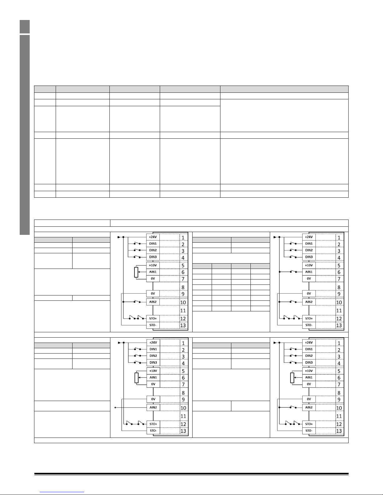
Optidrive P2 Advanced User Guide Rev 2.00
30
www.invertekdrives.com
Optidrive P2 Parameter Set Overview
1
1.7. Control Terminal Connections
For standard applications and operation, the basic control of the drive and functions of all drive input terminals can be configured using just
two parameters, P1-12 and P1-13. P1-12 is used to define the source of all control commands and the primary speed reference source. P1-13
then allows fast selection of Analog and Digital Input functions based on a selection table.
For applications which require a combination of control source and input functions which are not available using the standard approach,
control sources can be manually configured in Parameter Group 9. To enable this User Defined function, both P1-12 and P1-13 must be set to
0. Parameter Group 9 is described in section 1.4.
1.7.1. P1-12 Function
P1-12 is used to select the main control source of the drive and the main speed reference according to the following table
P1-12
Function
Control Source
Main Speed Reference
Notes
0
Terminal Control
Terminals
Analog Input 1
1
Keypad Control
Keypad / Terminals
Motorised Pot / Keypad
When keypad mode is selected, the default operation of
the drive requires the keypad Start & Stop buttons are
used to control the drive. This can be changed using P237 to allow the drive to be started from Digital Input 1
directly.
2
Keypad Control
Keypad / Terminals
Motorised Pot / Keypad
3
Terminal Control PID
Terminals
PID Controller
4
Fieldbus Control
Fieldbus Interface
Fieldbus refers to the on-board Modbus RTU connection
via the built in RJ45 connection or the optional Fieldbus
Plug in modules. If no module is fitted, the drive
responds to the Modbus RTU interface. If a fieldbus
Interface is fitted, Modbus RTU communication is
disabled, and the drive responds to control inputs from
the Fieldbus.
5
Slave Mode
From Master Drive
From Master Drive
6
CAN bus
CAN bus
CAN Bus
1.7.2. P1-13 Function
P1-13 is used to select a pre-assigned list of functions to the digital inputs. These factory set assignments are designed to cater for the majority
of standard applications.
P1-13 = 0
Input functions defined in Parameter Group 9. See section 1.4
P1-13 = 1
P1-13 = 2
Open
Closed
Open
Closed
Stop
Run
Stop
Run
Forward Rotation
Reverse Rotation
Forward Rotation
Reverse Rotation
Selected Speed
Reference
Preset Speed
Reference
Preset Speed Reference Selected as
follows:-
DIN3
AIN1
AIN2
Preset
Analog Input 1
OFF
OFF
OFF
P2-01
ON
OFF
OFF
P2-02
OFF
ON
OFF
P2-03
ON
ON
OFF
P2-04
OFF
OFF
ON
P2-05
Preset Speed 1
Preset Speed 2
ON
OFF
ON
P2-06
Safe Torque OFF inputs
Contacts must be closed to operate drive
OFF
ON
ON
P2-07
ON
ON
ON
P2-08
Safe Torque OFF inputs
Contacts must be closed to operate drive
P1-13 = 3
P1-13 = 4 Open
Closed
Open
Closed
Stop
Run
Stop
Run
Forward Rotation
Reverse Rotation
Forward Rotation
Reverse Rotation
Selected Speed
Reference
Preset Speed 1
Selected Speed
Reference
Preset Speed 1
Analog Input 1
Analog Input 1
Analog Input 2 (E.g. Torque Reference)
Decel ramp 1
(P1-04)
Decel Ramp 2
(P8-11)
Safe Torque OFF inputs
Contacts must be closed to operate drive
Safe Torque OFF inputs
Contacts must be closed to operate drive
Page 31
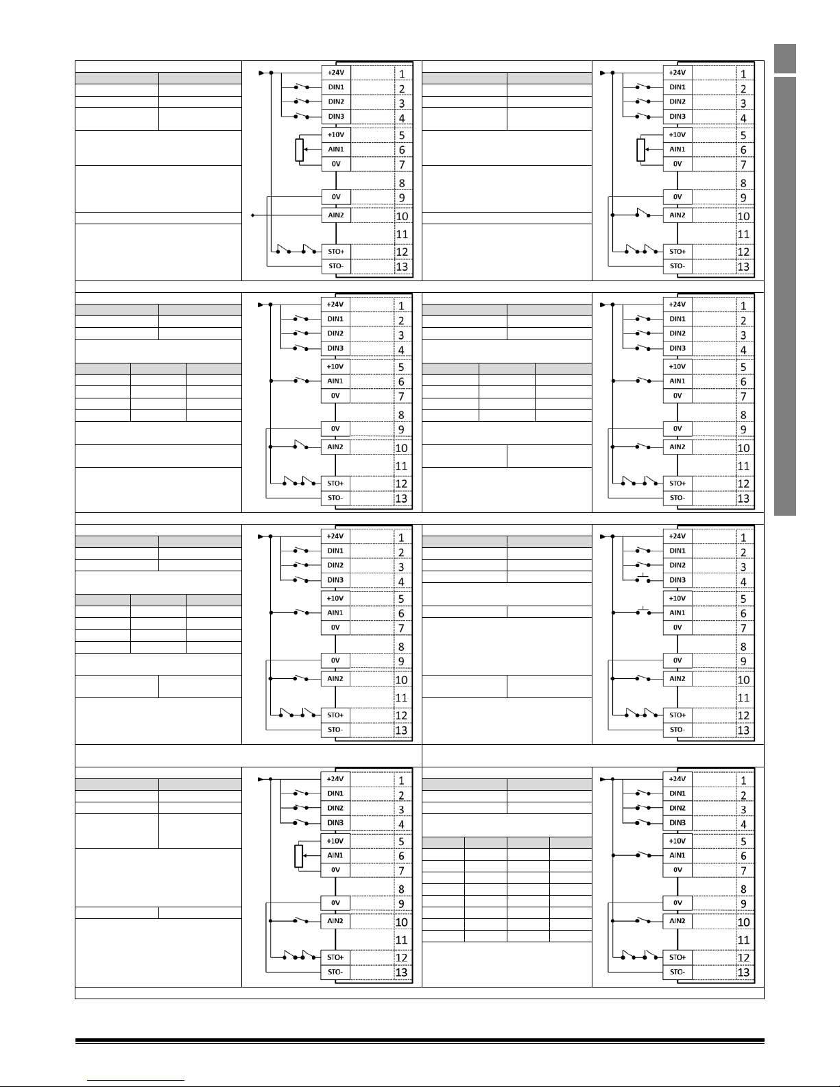
Optidrive P2 Advanced User Guide Rev 2.00
www.invertekdrives.com
31
Optidrive P2 Parameter Set Overview
1
P1-13 = 5
P1-13 = 6 Open
Closed
Open
Closed
Stop
Run
Stop
Run
Forward Rotation
Reverse Rotation
Forward Rotation
Reverse Rotation
Selected Speed
Reference
Analog Input 2
Speed Reference
Selected Speed
Reference
Preset Speed 1
Analog Input 1
Analog Input 1
Analog Input 2
External Trip
Safe Torque OFF inputs
Contacts must be closed to operate drive
Safe Torque OFF inputs
Contacts must be closed to operate drive
P1-13 = 7
P1-13 = 8
Open
Closed
Open
Closed
Stop
Run
Stop
Run
Forward Rotation
Reverse Rotation
Forward Rotation
Reverse Rotation
Preset Speed Reference Selected as
follows:-
Preset Speed Reference Selected as
follows:-
DIN3
AIN1
Preset
DIN3
AIN1
Preset
OFF
OFF
P2-01
OFF
OFF
P2-01
ON
OFF
P2-02
ON
OFF
P2-02
OFF
ON
P2-03
OFF
ON
P2-03
ON
ON
P2-04
ON
ON
P2-04
External Trip
Decel ramp 1
(P1-04)
Decel Ramp 2
(P2-25)
Safe Torque OFF inputs
Contacts must be closed to operate drive
Safe Torque OFF inputs
Contacts must be closed to operate drive
P1-13 = 9
P1-13 = 10
Open
Closed
Open
Closed
Stop
Run
Stop
Run
Forward Rotation
Reverse Rotation
Forward Rotation
Reverse Rotation
Preset Speed Reference Selected as
follows:-
Increase Speed1)
DIN3
AIN1
Preset
OFF
OFF
P2-01
Decrease Speed1)
ON
OFF
P2-02
OFF
ON
P2-03
ON
ON
P2-04
Selected Speed
Reference
Preset Speeds
Reference 1 - 4
Selected Speed
Reference
Preset Speed 1
Safe Torque OFF inputs
Contacts must be closed to operate drive
Safe Torque OFF inputs
Contacts must be closed to operate drive
1) Increase / Decrease speed function only works if the Selected Speed
reference is the Motorised Pot (P1-12 = 1 or 2)
P1-13 = 11
P1-13 = 12 Open
Closed
Open
Closed
Stop
Run Forward
Stop
Run Forward
Stop
Run Reverse
Stop
Run Reverse
Selected Speed
Reference
Preset Speed
Reference
Preset Speed Reference Selected as
follows:-
DIN3
AIN1
AIN2
Preset
Analog Input 1
OFF
OFF
OFF
P2-01
ON
OFF
OFF
P2-02
OFF
ON
OFF
P2-03
ON
ON
OFF
P2-04
OFF
OFF
ON
P2-05
Preset Speed 1
Preset Speed 2
ON
OFF
ON
P2-06
Safe Torque OFF inputs
Contacts must be closed to operate drive
OFF
ON
ON
P2-07
ON
ON
ON
P2-08
Safe Torque OFF inputs
Contacts must be closed to operate drive
Page 32
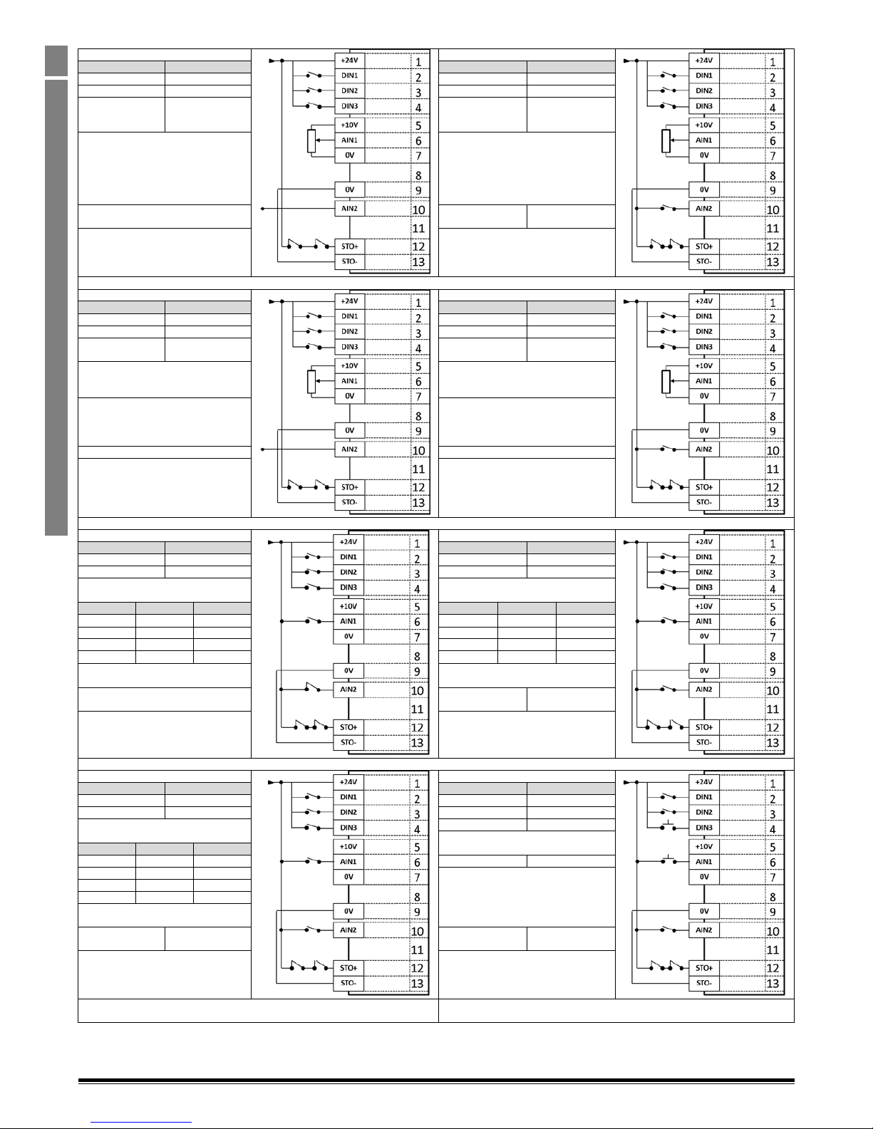
Optidrive P2 Advanced User Guide Rev 2.00
32
www.invertekdrives.com
Optidrive P2 Parameter Set Overview
1
P1-13 = 13
P1-13 = 14 Open
Closed
Open
Closed
Stop
Run Forward
Stop
Run Forward
Stop
Run Reverse
Stop
Run Reverse
Selected Speed
Reference
Preset Speed 1
Selected Speed
Reference
Preset Speed 1
Analog Input 1
Analog Input 1
Analog Input 2 (E.g. Torque Reference)
Decel ramp 1
(P1-04)
Decel Ramp 2
(P8-11)
Safe Torque OFF inputs
Contacts must be closed to operate drive
Safe Torque OFF inputs
Contacts must be closed to operate drive
P1-13 = 15
P1-13 = 16
Open
Closed
Open
Closed
Stop
Run Forward
Stop
Run Forward
Stop
Run Reverse
Stop
Run Reverse
Selected Speed
Reference
Analog Input 2
Speed Reference
Selected Speed
Reference
Preset Speed 1
Analog Input 1
Analog Input 1
Analog Input 2
External Trip
Safe Torque OFF inputs
Contacts must be closed to operate drive
Safe Torque OFF inputs
Contacts must be closed to operate drive
P1-13 = 17
P1-13 = 18 Open
Closed
Open
Closed
Stop
Run Forward
Stop
Run Forward
Stop
Run Reverse
Stop
Run Reverse
Preset Speed Reference Selected as
follows:-
Preset Speed Reference Selected as
follows:-
DIN3
AIN1
Preset
DIN3
AIN1
Preset
OFF
OFF
P2-01
OFF
OFF
P2-01
ON
OFF
P2-02
ON
OFF
P2-02
OFF
ON
P2-03
OFF
ON
P2-03
ON
ON
P2-04
ON
ON
P2-04
External Trip
Decel ramp 1
(P1-04)
Decel Ramp 2
(P2-25)
Safe Torque OFF inputs
Contacts must be closed to operate drive
Safe Torque OFF inputs
Contacts must be closed to operate drive
P1-13 = 19
P1-13 = 20 Open
Closed
Open
Closed
Stop
Run Forward
Stop
Run Forward
Stop
Run Reverse
Stop
Run Reverse
Preset Speed Reference Selected as
follows:-
Increase Speed1)
DIN3
AIN1
Preset
OFF
OFF
P2-01
Decrease Speed1)
ON
OFF
P2-02 OFF
ON
P2-03
ON
ON
P2-04
Selected Speed
Reference
Preset Speeds
Reference 1 - 4
Selected Speed
Reference
Preset Speed 1
Safe Torque OFF inputs
Contacts must be closed to operate drive
Safe Torque OFF inputs
Contacts must be closed to operate drive
1) Increase / Decrease speed function only works if the Selected Speed
reference is the Motorised Pot (P1-12 = 1 or 2)
Page 33
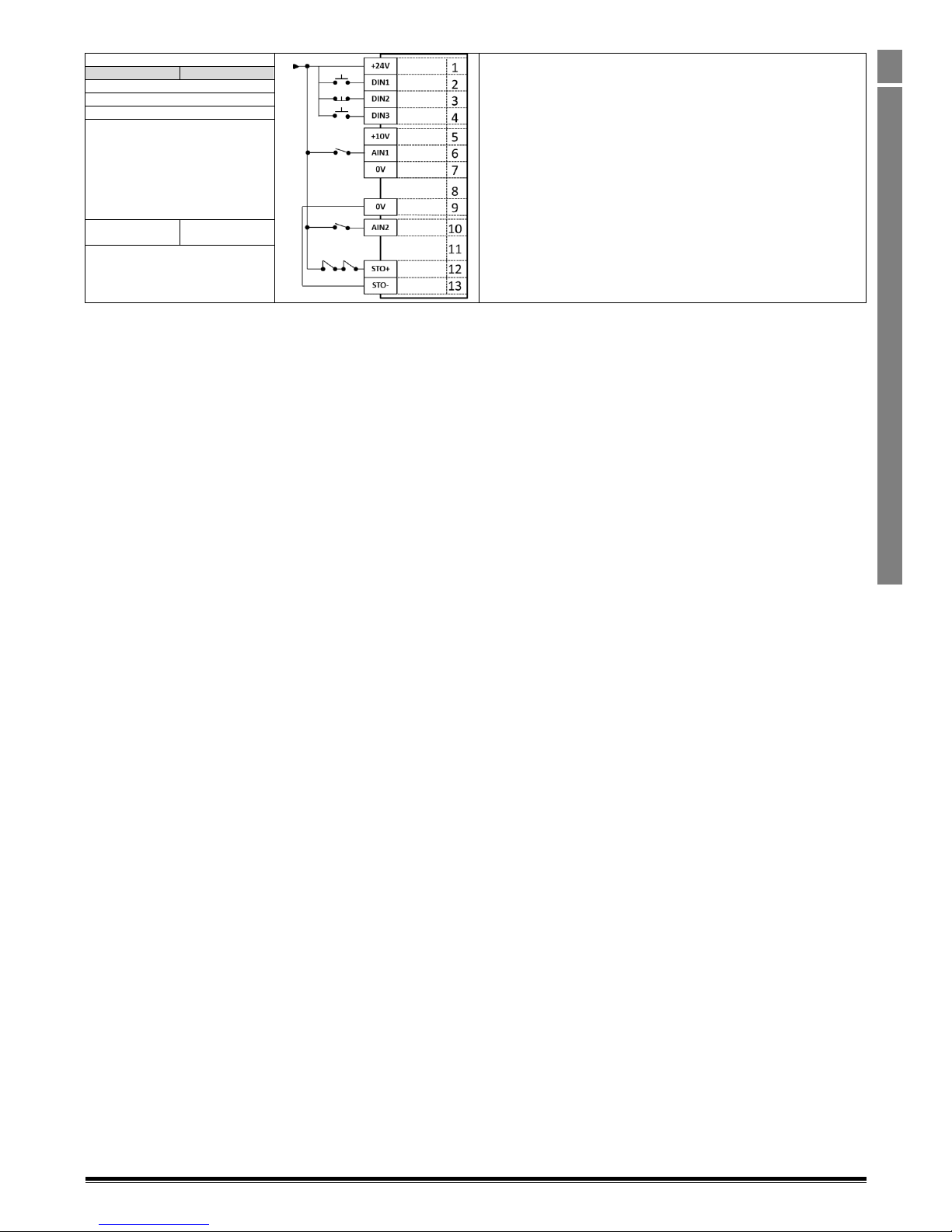
Optidrive P2 Advanced User Guide Rev 2.00
www.invertekdrives.com
33
0
P1-13 = 21
Open
Closed
N.O. Contact - Start Forward
N.C. Closed Contact – Stop
N.O. Contact – Start Reverse
Analog Input 1
Selected Speed
Reference
Preset Speed 1
Safe Torque OFF inputs
Contacts must be closed to operate drive
Page 34
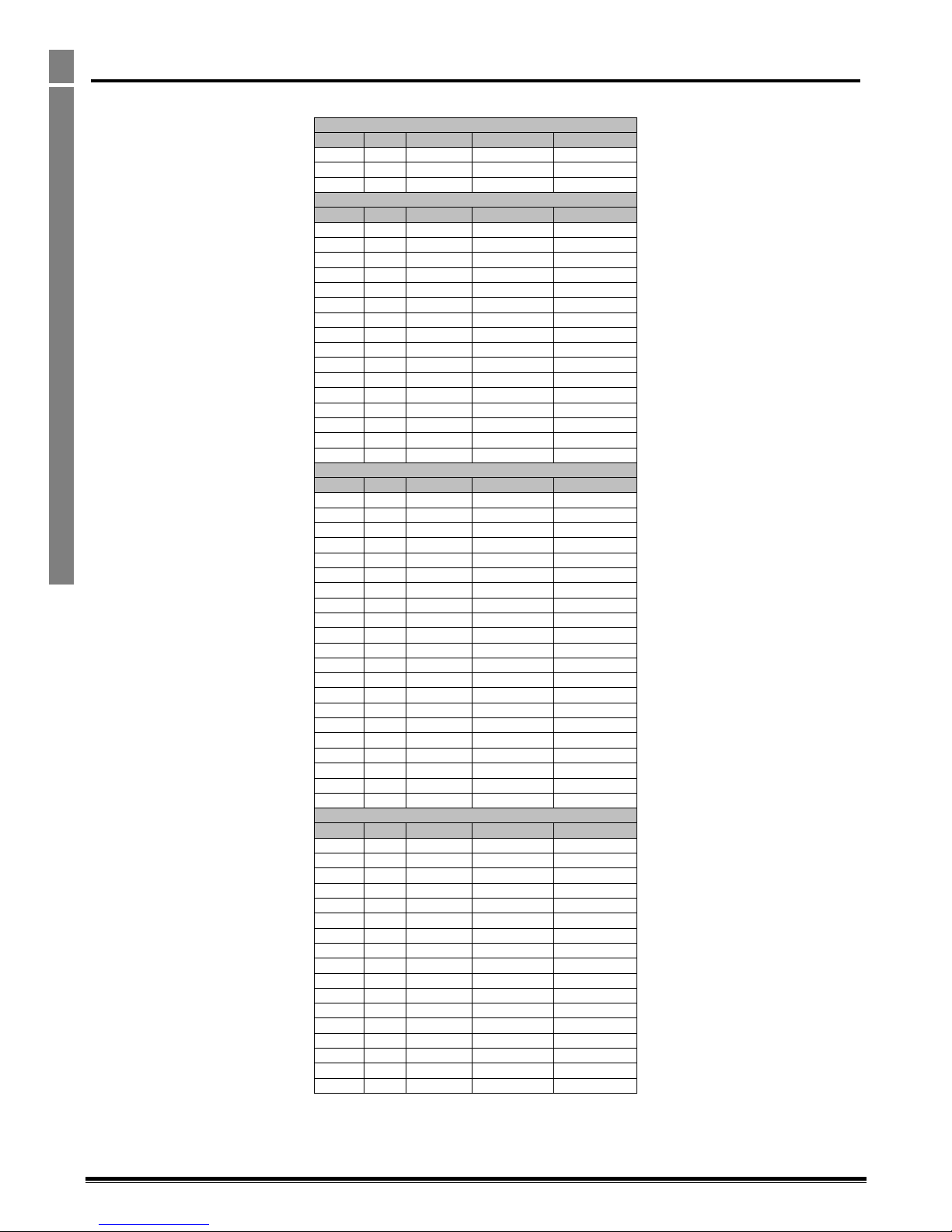
Optidrive P2 Advanced User Guide Rev 2.00
34
www.invertekdrives.com
Drive Model Specific Parameter Variations
2
2. Drive Model Specific Parameter Variations
2.1. Available Effective Switching Frequency Options
230 Volt, 1 Phase Models
kW
HP
Default
Minimum
Maximum
0.75 1 16 kHz
4 kHz
32 kHz
1.5 2 16 KHz
4 kHz
32 kHz
2.2 3 16 kHz
4 kHz
32 kHz
230 Volt, 3 Phase Models
kW
HP
Default
Minimum
Maximum
0.75 1 16 kHz
4 kHz
32 kHz
1.5 2 16 kHz
4 kHz
32 kHz
2.2 3 16 kHz
4 kHz
32 kHz
3 4 16 kHz
4 kHz
32 kHz
4 5 16 kHz
4 kHz
32 kHz
5.5
7.5
16 kHz
4 kHz
16 kHz
7.5
10
8 kHz
4 kHz
24 kHz
11
15
8 kHz
4 kHz
24 kHz
15
20
8 kHz
4 kHz
24 kHz
18.5
25
8 kHz
4 kHz
24 kHz
22
30
8 kHz
4 kHz
16 kHz
30
40
4 kHz
4 kHz
16 kHz
37
50
4 kHz
4 kHz
12 kHz
45
60
4 kHz
4 kHz
8 kHz
55
75
4 kHz
4 kHz
8 kHz
75
100
4 kHz
4 kHz
8 kHz
400 Volt, 3 Phase Models
kW
HP
Default
Minimum
Maximum
0.75 1 8 kHz
4 kHz
32 kHz
1.5 2 8 kHz
4 kHz
32 kHz
2.2 3 8 kHz
4 kHz
32 kHz
4 5 8 kHz
4 kHz
32 kHz
5.5
7.5
8 kHz
4 kHz
24 kHz
7.5
10
8 kHz
4 kHz
24 kHz
11
15
8 kHz
4 kHz
16 kHz
15
20
8 kHz
4 kHz
24 kHz
18.5
25
8 kHz
4 kHz
24 kHz
22
30
8 kHz
4 kHz
24 kHz
30
40
8 kHz
4 kHz
24 kHz
37
50
8 kHz
4 kHz
24 kHz
45
60
4 kHz
4 kHz
16 kHz
55
75
4 kHz
4 kHz
16 kHz
75
120
4 kHz
4 kHz
12 kHz
90
150
4 kHz
4 kHz
8 kHz
110
175
4 kHz
4 kHz
8 kHz
132
200
4 kHz
4 kHz
8 kHz
160
250
4 kHz
4 kHz
8 kHz
200
300
4 kHz
4 kHz
4 kHz
250
350
4 kHz
4 kHz
4 kHz
600 Volt, 3 Phase Models
kW
HP
Default
Minimum
Maximum
0.75 1 8 kHz
4 kHz
24 kHz
1.5 2 8 kHz
4 kHz
24 kHz
2.2 3 8 kHz
4 kHz
24 kHz
4 5 8 kHz
4 kHz
24 kHz
5.5
7.5
8 kHz
4 kHz
24 kHz
7.5
10
8 kHz
4 kHz
24 kHz
11
15
8 kHz
4 kHz
24 kHz
15
20
8 kHz
4 kHz
16 kHz
18.5
25
8 kHz
4 kHz
24 kHz
22
30
8 kHz
4 kHz
24 kHz
30
40
8 kHz
4 kHz
24 kHz
37
50
8 kHz
4 kHz
24 kHz
45
60
8 kHz
4 kHz
24 kHz
55
75
4 kHz
4 kHz
16 kHz
75
120
4 kHz
4 kHz
16 kHz
90
150
4 kHz
4 kHz
12 kHz
110
175
4 kHz
4 kHz
12 kHz
Page 35
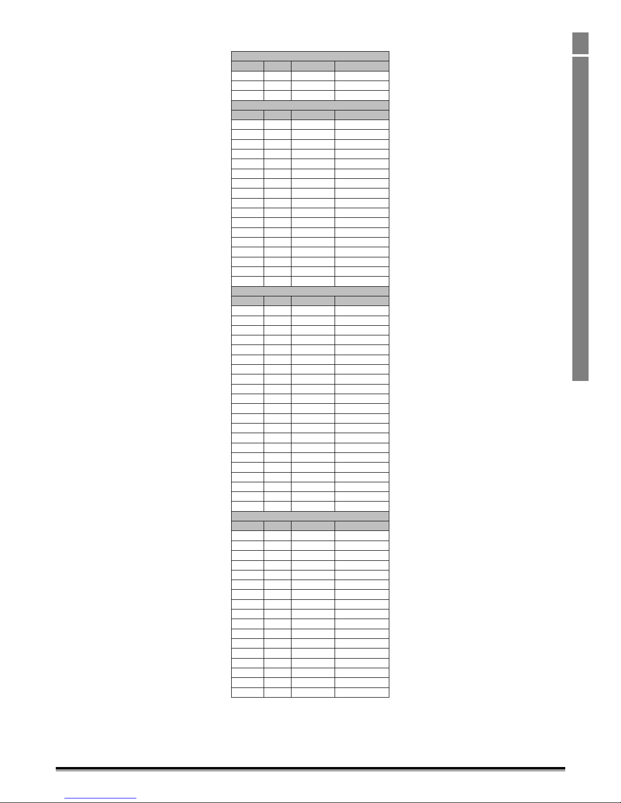
Optidrive P2 Advanced User Guide Rev 2.00
www.invertekdrives.com
35
Drive Model Specific Parameter Variations
2
2.2. V/F Mode Voltage Boost Setting Options
230 Volt, 1 Phase Input Models
kW
HP
Default
Maximum
0.75 1 2.5%
30.0%
1.5 2 2.5%
30.0%
2.2 3 2.5%
30.0%
230 Volt, 3 Phase Input Models
kW
HP
Default
Maximum
0.75 1 2.5%
30.0%
1.5 2 2.5%
30.0%
2.2 3 2.5%
30.0%
3 4 2.0%
20.0%
4 5 1.5%
20.0%
5.5
7.5
1.5%
20.0%
7.5
10
1.5%
20.0%
11
15
1.5%
20.0%
15
20
1.0%
20.0%
18.5
25
1.0%
20.0%
22
30
1.0%
15.0%
30
40
1.0%
15.0%
37
50
1.0%
15.0%
45
60
1.0%
15.0%
55
75
0.5%
15.0%
75
100
0.5%
15.0%
90
125
0.5%
15.0%
400 Volt 3 Phase Input Models
kW
HP
Default
Maximum
0.75 1 2.5%
30.0%
1.5 2 2.5%
30.0%
2.2 3 2.5%
30.0%
4 5 2.5%
30.0%
5.5
7.5
2.0%
20.0%
7.5
10
1.5%
20.0%
11
15
1.5%
20.0%
15
20
1.5%
20.0%
18.5
25
1.5%
20.0%
22
30
1.5%
20.0%
30
40
1.0%
20.0%
37
50
1.0%
20.0%
45
60
1.0%
15.0%
55
75
1.0%
15.0%
75
120
1.0%
15.0%
90
150
1.0%
15.0%
110
175
0.5%
15.0%
132
200
0.5%
15.0%
160
250
0.5%
15.0%
200
300
0.2%
10.0%
250
350
0.2%
10.0%
600 Volt 3 Phase Input Models
kW
HP
Default
Maximum
0.75 1 2.5%
30.0%
1.5 2 2.5%
30.0%
2.2 3 2.5%
30.0%
4 5 2.5%
30.0%
5.5
7.5
2.5%
20.0%
7.5
10
2.0%
20.0%
11
15
1.5%
20.0%
15
20
1.0%
20.0%
18.5
25
1.5%
20.0%
22
30
1.5%
20.0%
30
40
1.5%
20.0%
37
50
1.0%
20.0%
45
60
1.0%
20.0%
55
75
1.0%
15.0%
75
120
1.0%
15.0%
90
150
1.0%
15.0%
110
175
1.0%
15.0%
Page 36

Optidrive P2 Advanced User Guide Rev 2.00
36
www.invertekdrives.com
Embedded Firmware Functions
3
3. Embedded Firmware Functions
3.1. 24 Hour Time Clock
Optidrive P2 includes a 24 hour time clock, accessible through the Function Block Editor. This allows time based functions to be realised. The
accuracy of the clock varies between drives, and a function is included to allow fine tuning of the timer function. The internal time value may
be read from or written to within the function block editor.
Note that the value is not retained during power off.
3.1.1. 24 Hour Timer Trim Adjustment
The internal 24 volt timer includes a trim function, adjusted as follwos :-
With the drive in display showing “Stop” or “Inhibit”, press and hold the Up and Down keypad keys for >1s
The display will show the present timer value in hours and minutes as xxhxx, and can be adjusted if desired using the Up and Down keys.
Following setting of the desired time, press the Navigate button
The display will now show the timer trim value percentage, displayed as “t0.00”. This can be adjusted using the Up and Down keys to a
maximum of + / - 3.00%
Press the Navigate key to exit the trim adjustment
Press the Up and Down keys together to exit the timer adjustment, or alternatively, press the Stop key to exit without saving.
If the internal 24 hour timer operates faster than is correct, a positive trim value is required. The trim value can be checked by leaving the drive
powered over 24 hours and checking the timer value. The correct trim setting should be Error Minutes / Total Minutes, where Error Minutes is
the difference between the drive displayed minutes and the actual minuts that have elapsed.
Page 37
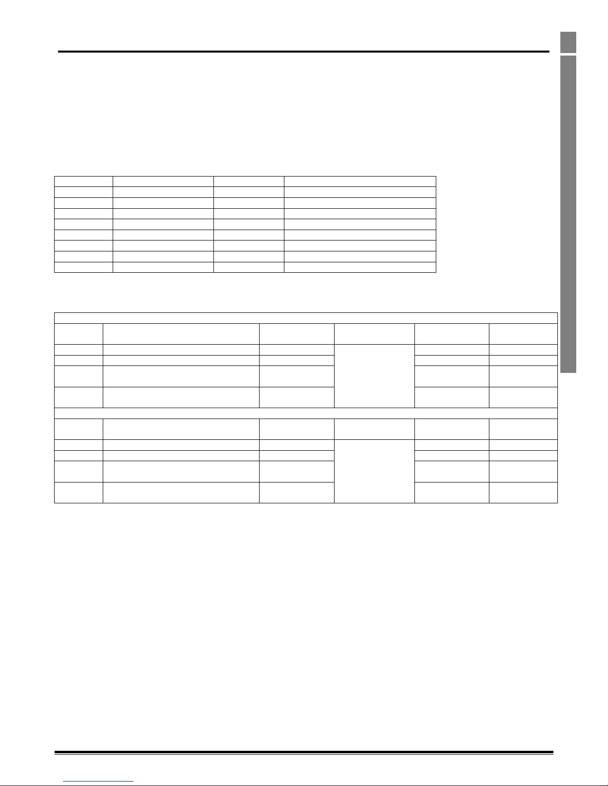
Optidrive P2 Advanced User Guide Rev 2.00
www.invertekdrives.com
37
Fieldbus Interface Support
4
4. Fieldbus Interface Support
4.1. Fieldbus Interface Options
Optidrive P2 supports a number of Fieldbus Interface Options, either directly on-board the drive (Modbus RTU, CAN Open) or using optional
plug in interfaces (e.g. Profibus DP). Where possible, these fieldbus interfaces also provide access to the drive parameters. This chapter details
the parameters that can be accessed, and any scaling used when reading or writing (where permissible) to the parameters.
Only one Fieldbus can be supported at a time. When a Fieldbus module is inserted into the drive (e.g. Profibus DP), the on-board fieldbus
interfaces such as Modbus RTU and CANbus are disabled. Also, only one internal bus can be supported, hence it is not possible to
simultaneously use CANbus and Modbus RTU.
4.2. Fieldbus Support Overview
Optidrive P2 provides support for the following fieldbus networks and functions
Fieldbus
Interface
Drive Control
Drive Parameter Access
Modbus RTU
On-board RJ45
Yes
Access to all Writable Parameters
Modbus TCP
Optional OPT-2-MODIP-IN
Yes
Access to all Writable Parameters
CAN bus
On-board RJ45
Yes
Access to all Writable Parameters
Profibus DP
Optional OPT-2-PROFB-IN
Yes
DPV-1 Access to all Writable Parameters
Profinet IO
Optional OPT-2-PFNET-IN
Yes
Access to all Writable Parameters
DeviceNet
Optional OPT-2-DEVNT-IN
Yes
Access to all Writable Parameters
Ethernet IP
Optional OPT-2-ETHNT-IN
Yes
Access to all Writable Parameters
Ethercat
Optional OPT-2-ETHCT-IN
Yes
-
4.3. Simple Drive Control
For the simplest implementation, all fieldbus systems allow control and monitoring of the drive using a 4 words input, 4 words output cyclic
process data exchange. The words are defined as follows :-
Master > Drive
Reference
Function
Scaling
Fieldbus Reference
Modbus RTU
Register
Modbus TCP
Register
Word 1
Drive control Word (Fixed)
N/A
PDI0*
1
1
Word 2
Frequency Setpoint (Fixed)
500 = 50.0Hz
2
2
Word 3
Torque Setpoint (or user selected value in
P5-14)
1000 = 100.0%
3
3
Word 4
Fieldbus Ramps (or user selected value in
P5-13)
3000 = 30.0
Seconds
4
4
Drive > Master
Reference
Function
Scaling
Fieldbus Reference
Modbus RTU
Register
Modbus TCP
Register
Word 1
Drive Status Word (Fixed)
N/A
PDO0*
6
256
Word 2
Output Frequency (Fixed)
500 = 50.0Hz
7
257
Word 3
Output Current (or user selected value in
P5-12)
100 = 10.0A
8
258
Word 4
Output Torque (or user selected value in
P5-08)
1000 = 100.0%
9
259
*These references apply to all other fieldbus systems
Page 38
Optidrive P2 Advanced User Guide Rev 2.00
38
www.invertekdrives.com
Fieldbus Interface Support
4
4.4. Drive Control Word Definition :-
Bit
Function
0
0 : Stop
1 : Run
1
0 : Normal Operation
1 : Fast Stop (P2-25)
2
0 : No Function
1 : Reset Fault
3
0 : Normal Operation
1 : Coast Stop
4.5. Drive Status Word Definition
Bit
Function
0
0 : Drive Stopped
1 : Drive Running
1
0 : Drive Healthy
1 : Drive Tripped
2
No Function
3
0 : Drive Ready
1 : Drive Inhibit
4
0 : Maintenance Time Not Elapsed
1 : Maintenance Time Elapsed
5
0 : Not In Standby
1 : In Standby
6
No Function
7
No Function
8
No Function
9
Fault Code as listed in section 5
10
11
12
13
14
15
4.6. Parameter Access Overview
The accessible parameter numbers and respective scaling are listed in the following tables. The method to access the parameters depends on
the fieldbus type in use as described in the following section.
The R/W column indicates whether the values are Writeable as well as readable (R/W) or Read Only (R)
The data types for the parameter are defined as follows :WORD Hexadecimal Word
U16 Unsigned 16 Bit Value
S16 Signed 16 Bit Value
4.6.1. Modbus RTU
The table shows the Modbus RTU register number corresponding to each parameter value. All values are holding registers.
All User Adjustable parameters (Groups 1 to 9) are accessible by Modbus, except those that would directly affect the Modbus
communications, e.g.
P5-01 Communication Protocol Select
P5-02 Drive Fieldbus Address
P5-03 Modbus RTU Baud Rate
P5-04 Modbus RTU Data Format
All parameter values can be read from the drive and written to, depending on the operating mode of the drive – some parameters cannot be
changed whilst the drive is enabled for example.
Parameter access via Modbus RTU is only possible when no other communication interface is installed in the drive, e.g. it cannot be used
simultaneously with a Profibus DP interface present.
When accessing a drive parameter via Modbus RTU, the Register number for the parameter is the same as the parameter number,
E.g. Parameter P1-01 = Modbus Register 101.
Modbus RTU supports sixteen bit integer values; hence parameter values are transferred as integers, ignoring the decimal point.
E.g. Read Value of P1-01 = 500, therefore this is 50.0Hz.
Scaling applied to other parameters is described in the tables.
In addition to the parameter specific register listed, Optidrive P2 also supports indirect Read and Write Access to all addressable parameters
using only two Registers.
Page 39

Optidrive P2 Advanced User Guide Rev 2.00
www.invertekdrives.com
39
Fieldbus Interface Support
4
Register 44 : Parameter Number
When a value is written to Register 44, the present value of that parameter will be transferred to Register 45. Reading Register 45 will allow
the user to read the present parameter value.
Register 45 : Parameter Value
This register is used for Read / Write Transfer of parameter data.
Operation : Parameter Read
In order to read the value of a parameter
- WRITE the parameter number to register 44, e.g. for P1-01, write “101” to register 44
- READ the value of Register 45
- The present value in internal format is returned
Operation : Parameter Write
In order to write the value of a parameter
- WRITE the parameter n umber to register 44, e.g. for P1-01, write “101” to register 44
- WRITE the new parameter data setting to register 45 in the correct internal format
READ the value of register 45 to confirm the change
4.6.2. CAN Open
The table shows the Index and Sub Index required to address each parameter. All User Adjustable parameters (Groups 1 to 9) are accessible by
CAN, except those that would directly affect the communications.
All parameter values can be read from the drive and written to, depending on the operating mode of the drive – some parameters cannot be
changed whilst the drive is enabled for example.
Parameter access via CAN is only possible when no other communication interface is installed in the drive, e.g. it cannot be used
simultaneously with a Profibus DP interface present.
4.6.3. Profibus DP
Access to drive parameters uses Profibus DPV-1 read / write services. All User Adjustable Parameters are accessible.
All parameter values can be read from the drive and written to, depending on the operating mode of the drive – some parameters cannot be
changed whilst the drive is enabled for example.
The table gives the slot number and index required to access each parameter.
4.6.4. DeviceNet
Access to drive parameters uses vendor specific CIP objects (Class A2h). All User Adjustable Parameters are accessible.
All parameter values can be read from the drive and written to, depending on the operating mode of the drive – some parameters cannot be
changed whilst the drive is enabled for example.
The table gives the Instance Attribute, Name and Value (X) for each parameter.
4.6.5. Ethernet IP
Access to drive parameters uses vendor specific CIP objects (Class A2h). All User Adjustable Parameters are accessible.
All parameter values can be read from the drive and written to, depending on the operating mode of the drive – some parameters cannot be
changed whilst the drive is enabled for example.
The table gives the Instance Attribute, Name and Value (X) for each parameter.
4.6.6. EtherCat
All parameter values can be read from the drive and written to, depending on the operating mode of the drive – some parameters cannot be
changed whilst the drive is enabled for example.
The table gives the Instance Attribute for each parameter.
4.6.7. Modbus TCP
The table shows the Modbus TCP register number corresponding to each parameter value. All values are holding registers.
All parameter values can be read from the drive and written to, depending on the operating mode of the drive – some parameters cannot be
changed whilst the drive is enabled for example.
4.6.8. Profinet IO
Access to drive parameters via Profinet uses the Record Data Read / Write service of API0. The table gives the API, Slot, Sub Slot, and Index for
each parameter.
All parameter values can be read from the drive and written to, depending on the operating mode of the drive – some parameters cannot be
changed whilst the drive is enabled for example.
Page 40
40
Parameter Access Tables
www.invertekdrives.com
Optidrive P2 Advanced User Guide Revision 2.00
4.7. Parameter Access Tables
4.7.1. Group 1 : Basic Parameter Set (Level 1)
Parameter
Number
R/W
Modbus
RTU
Register
Number
CAN
Open
Index
CAN
Open
Sub
Index
Profibus
DP
DeviceNet
EtherNet
IP
EtherCAT
Modbus
TCP
Profinet
IO
Parameter Name
Setting Range
Scaling
Type
P1-01
R/W
101
2065h
0h
0, 100
A2h, 101, X
A2h, 101, X
2065h
628
0, 0, 1, 0065h
Max Frequency Limit
0 to 30000
3000 = 50.0Hz
U16
P1-02
R/W
102
2066h
0h
0, 101
A2h, 102, X
A2h, 102, X
2066h
629
0, 0, 1, 0066h
Min Frequency Limit
0 to 30000 (Limited by P1-01 Setting)
3000 = 50.0Hz
U16
P1-03
R/W
103
2067h
0h
0, 102
A2h, 103, X
A2h, 103, X
2067h
630
0, 0, 1, 0067h
Acceleration Ramp Time
0 to 6000
300 = 30.0s
U16
P1-04
R/W
104
2068h
0h
0, 103
A2h, 104, X
A2h, 104, X
2068h
631
0, 0, 1, 0068h
Deceleration Ramp Time
0 to 6000
300 = 30.0s
U16
P1-05
R/W
105
2069h
0h
0, 104
A2h, 105, X
A2h, 105, X
2069h
632
0, 0, 1, 0069h
Stop mode
0: Ramp to Stop
1: Coast to Stop
2 = Ramp to Stop, Brake Transistor Enabled
3 = Coast to Stop, Brake Transistor Enabled
U16
P1-06
R/W
106
206Ah
0h
0, 105
A2h, 106, X
A2h, 106, X
206Ah
633
0, 0, 1, 006Ah
Energy optimiser
0: Disable
1: Enable
WORD
P1-07
R/W
107
206Bh
0h
0, 106
A2h, 107, X
A2h, 107, X
206Bh
634
0, 0, 1, 006Bh
Motor rated voltage
0V, 20V to 250V
0V, 20V to 500V
0V, 20V to 600V
230 = 230 V
U16
P1-08
R/W
108
206Ch
0h
0, 107
A2h, 108, X
A2h, 108, X
206Ch
635
0, 0, 1, 006Ch
Motor rated current
20% to 100% of drive rated current
1 = 0.1A
U16
P1-09
R/W
109
206Dh
0h
0, 108
A2h, 109, X
A2h, 109, X
206Dh
636
0, 0, 1, 006Dh
Motor rated frequency
25 to 500Hz
50 = 50Hz
U16
P1-10
R/W
110
206Eh
0h
0, 109
A2h, 110, X
A2h, 110, X
206Eh
637
0, 0, 1, 006Eh
Motor rated speed
0 to 30 000rpm
1500 = 1500rpm
U16
P1-11
R/W
111
206Fh
0h
0, 110
A2h, 111, X
A2h, 111, X
206Fh
638
0, 0, 1, 006Fh
V/F Voltage Boost
Auto, 0.1 to 20%
-1 = Auto
0 = Disabled
1 = 0.1%
S16
P1-12
R/W
112
2070h
0h
0, 111
A2h, 112, X
A2h, 112, X
2070h
639
0, 0, 1, 0070h
Control mode
0: Terminal mode
1: Keypad mode (Unipolar)
2: Keypad mode (Bipolar + direction toggle)
3: User PID mode
4: Fieldbus (Modbus, Profibus etc.)
5: Slave mode
U16
P1-13
R/W
113
2071h
0h
0, 112
A2h, 113, X
A2h, 113, X
2071h
640
0, 0, 1, 0071h
Digital inputs function select
0: User defined
1...20 see table
U16
P1-14
R/W
114
2072h
0h
0, 113
A2h, 114, X
A2h, 114, X
2072h
641
0, 0, 1, 0072h
Extended Menu Access code
0 to 30 000
U16
Page 41
41
Parameter Access Tables
www.invertekdrives.com
Optidrive P2 Advanced User Guide Revision 2.00
4.7.2. Group 2 : Extended parameter set (Level 2)
Parameter
Number
R/W
Modbus
RTU
Register
Number
CAN
Open
Index
CAN
Open
Sub
Index
Profibus
DP
DeviceNet
EtherNet
IP
EtherCAT
Modbus
TCP
Profinet
IO
Parameter Name
Setting Range
Scaling
Type
P2-01
R/W
201
20C9h
0h
0, 200
A2h, 201, X
A2h, 201, X
20C9h
728
0, 0, 1, 00C9h
Preset speed 1
0 to 30000 (Limited by P1-01 Setting)
3000 = 50.0Hz
U16
P2-02
R/W
202
20CAh
0h
0, 201
A2h, 202, X
A2h, 202, X
20CAh
729
0, 0, 1, 00CAh
Preset speed 2
0 to 30000 (Limited by P1-01 Setting)
3000 = 50.0Hz
U16
P2-03
R/W
203
20CBh
0h
0, 202
A2h, 203, X
A2h, 203, X
20CBh
730
0, 0, 1, 00CBh
Preset speed 3
0 to 30000 (Limited by P1-01 Setting)
3000 = 50.0Hz
U16
P2-04
R/W
204
20CCh
0h
0, 203
A2h, 204, X
A2h, 204, X
20CCh
731
0, 0, 1, 00CCh
Preset speed 4
0 to 30000 (Limited by P1-01 Setting)
3000 = 50.0Hz
U16
P2-05
R/W
205
20CDh
0h
0, 204
A2h, 205, X
A2h, 205, X
20CDh
732
0, 0, 1, 00CDh
Preset speed 5
0 to 30000 (Limited by P1-01 Setting)
3000 = 50.0Hz
U16
P2-06
R/W
206
20CEh
0h
0, 205
A2h, 206, X
A2h, 206, X
20CEh
733
0, 0, 1, 00CEh
Preset speed 6
0 to 30000 (Limited by P1-01 Setting)
3000 = 50.0Hz
U16
P2-07
R/W
207
20CFh
0h
0, 206
A2h, 207, X
A2h, 207, X
20CFh
734
0, 0, 1, 00CFh
Preset speed 7
0 to 30000 (Limited by P1-01 Setting)
3000 = 50.0Hz
U16
P2-08
R/W
208
20D0h
0h
0, 207
A2h, 208, X
A2h, 208, X
20D0h
735
0, 0, 1, 00D0h
Preset speed 8
0 to 30000 (Limited by P1-01 Setting)
3000 = 50.0Hz
U16
P2-09
R/W
209
20D1h
0h
0, 208
A2h, 209, X
A2h, 209, X
20D1h
736
0, 0, 1, 00D1h
Skip frequency centre point
0 to 30000 (Limited by P1-01 Setting)
3000 = 50.0Hz
U16
P2-10
R/W
210
20D2h
0h
0, 209
A2h, 210, X
A2h, 210, X
20D2h
737
0, 0, 1, 00D2h
Skip frequency band
0 to 30000 (Limited by P1-01 Setting)
3000 = 50.0Hz
U16
P2-11
R/W
211
20D3h
0h
0, 210
A2h, 211, X
A2h, 211, X
20D3h
738
0, 0, 1, 00D3h
Analog output 1 function select
Digital Mode (0V or 24V only)
0: Drive running
1: Drive healthy
2: Motor at target speed
3: Motor Speed > 0
4: Motor Speed > limit
5: Motor Current > limit
6: Motor Torque > limit
7: 2nd Analog input > limit
(Limit set by P2-18, P2-19)
Analog Mode
8: Speed
9: Current
10: Torque
11: Power
U16
P2-12
R/W
212
20D4h
0h
0, 211
A2h, 212, X
A2h, 212, X
20D4h
739
0, 0, 1, 00D4h
Analog output 1 format
0 = 0…10V
1 = 10…0V
2 = 0-20mA
3 = 20-0mA
4 = 4-20mA
5 = 20-4mA
U16
P2-13
R/W
213
20D5h
0h
0, 212
A2h, 213, X
A2h, 213, X
20D5h
740
0, 0, 1, 00D5h
Analog output 2 function select
Digital Mode (0V or 24V only)
0: Drive running
1: Drive healthy
2: Motor at target speed
3: Motor Speed > 0
4: Motor Speed > limit
5: Motor Current > limit
6: Motor Torque > limit
7: 2nd Analog input > limit
(Limit set by P2-18, P2-19)
Analog Mode
8: Speed
9: Current
10: Torque
11: Power
U16
P2-14
R/W
214
20D6h
0h
0, 213
A2h, 214, X
A2h, 214, X
20D6h
741
0, 0, 1, 00D6h
Analog output 2 format
0 = 0…10V
1 = 10…0V
2 = 0-20mA
3 = 20-0mA
4 = 4-20mA
5 = 20-4mA
U16
Page 42
42
Parameter Access Tables
www.invertekdrives.com
Optidrive P2 Advanced User Guide Revision 2.00
Parameter
Number
R/W
Modbus
RTU
Register
Number
CAN
Open
Index
CAN
Open
Sub
Index
Profibus
DP
DeviceNet
EtherNet
IP
EtherCAT
Modbus
TCP
Profinet
IO
Parameter Name
Setting Range
Scaling
Type
P2-15
R/W
215
20D7h
0h
0, 214
A2h, 215, X
A2h, 215, X
20D7h
742
0, 0, 1, 00D7h
User relay 1 output function select
0: Drive running
1: Drive healthy
2: Motor at target speed
3: Motor Speed > 0
4: Motor Speed > limit
5: Motor Current > limit
6: Motor Torque > limit
7: 2nd Analog input > limit
U16
P2-16
R/W
216
20D8h
0h
0, 215
A2h, 216, X
A2h, 216, X
20D8h
743
0, 0, 1, 00D8h
User relay 1 upper limit
P2-17 to 2000
1 = 0.1%
U16
P2-17
R/W
217
20D9h
0h
0, 216
A2h, 217, X
A2h, 217, X
20D9h
744
0, 0, 1, 00D9h
User relay 1 lower limit
0 to P2-16
1 = 0.1%
U16
P2-18
R/W
218
20DAh
0h
0, 217
A2h, 218, X
A2h, 218, X
20DAh
745
0, 0, 1, 00DAh
User relay 2 output function select
0: Drive running
1: Drive healthy
2: Motor at target speed
3: Motor Speed > 0
4: Motor Speed > limit
5: Motor Current > limit
6: Motor Torque > limit
7: 2nd Analog input > limit
U16
P2-19
R/W
219
20DBh
0h
0, 218
A2h, 219, X
A2h, 219, X
20DBh
746
0, 0, 1, 00DBh
User relay 2 upper limit
P2-20 to 2000
1 = 0.1%
U16
P2-20
R/W
220
20DCh
0h
0, 219
A2h, 220, X
A2h, 220, X
20DCh
747
0, 0, 1, 00DCh
User relay 2 lower limit
0 to P2-19
1 = 0.1%
U16
P2-21
R/W
221
20DDh
0h
0, 220
A2h, 221, X
A2h, 221, X
20DDh
748
0, 0, 1, 00DDh
Display scaling factor
0 to 30000
1 = 0.001
U16
P2-22
R/W
222
20DEh
0h
0, 221
A2h, 222, X
A2h, 222, X
20DEh
749
0, 0, 1, 00DEh
Display scaling source
0: Motor Speed
1: Motor Current
2: 2nd Analog input
U16
P2-23
R/W
223
20DFh
0h
0, 222
A2h, 223, X
A2h, 223, X
20DFh
750
0, 0, 1, 00DFh
Zero Speed holding time
0 to 600
1 = 0.1
U16
P2-24
R/W
224
20E0h
0h
0, 223
A2h, 224, X
A2h, 224, X
20E0h
751
0, 0, 1, 00E0h
Effective switching frequency
0 = 4kHz
1 = 8kHz
2 = 12kHz
3 = 16kHz
4 = 24kHz
5 = 32kHz
U16
P2-25
R/W
225
20E1h
0h
0, 224
A2h, 225, X
A2h, 225, X
20E1h
752
0, 0, 1, 00E1h
Fast deceleration ramp time
0 to 3000
S2…S3 1 = 0.01s
S4…S7 1 = 0.1s
U16
P2-26
R/W
226
20E2h
0h
0, 225
A2h, 226, X
A2h, 226, X
20E2h
753
0, 0, 1, 00E2h
Spin start enable
0 : Disabled
1 : Enabled
1
WORD
P2-27
R/W
227
20E3h
0h
0, 226
A2h, 227, X
A2h, 227, X
20E3h
754
0, 0, 1, 00E3h
Standby mode
0 to 25000
1 = 0.01
U16
P2-28
R/W
228
20E4h
0h
0, 227
A2h, 228, X
A2h, 228, X
20E4h
755
0, 0, 1, 00E4h
Slave speed scaling control
0: Disabled
1: Preset by slave speed scaling
2: P2-33 scaling + analog in1 offset
3: P2-33 scaling + analog in1 scaling
U16
P2-29
R/W
229
20E5h
0h
0, 228
A2h, 229, X
A2h, 229, X
20E5h
756
0, 0, 1, 00E5h
Slave Speed scaling factor
-5000 to 5000
1 = 0.1
S16
P2-30
R/W
230
20E6h
0h
0, 229
A2h, 230, X
A2h, 230, X
20E6h
757
0, 0, 1, 00E6h
Analog input 1 format
0 = 0-10V
1 = -10-10V
2 = 0-20mA
3 = t 4-20mA
4 = r 4-20mA
5 = t 20-4mA
6 = r 20-4mA
U16
P2-31
R/W
231
20E7h
0h
0, 230
A2h, 231, X
A2h, 231, X
20E7h
758
0, 0, 1, 00E7h
Analog input 1 scaling
0 to 5000
1 = 0.1
U16
P2-32
R/W
232
20E8h
0h
0, 231
A2h, 232, X
A2h, 232, X
20E8h
759
0, 0, 1, 00E8h
Analog input 1 offset
-5000 to 5000
1 = 0.1
S16
Page 43
43
Parameter Access Tables
www.invertekdrives.com
Optidrive P2 Advanced User Guide Revision 2.00
Parameter
Number
R/W
Modbus
RTU
Register
Number
CAN
Open
Index
CAN
Open
Sub
Index
Profibus
DP
DeviceNet
EtherNet
IP
EtherCAT
Modbus
TCP
Profinet
IO
Parameter Name
Setting Range
Scaling
Type
P2-33
R/W
233
20E9h
0h
0, 232
A2h, 233, X
A2h, 233, X
20E9h
760
0, 0, 1, 00E9h
Analog input 2 format
0 = 0-10V
1 = Ptc-th
2 = 0-20mA
3 = t 4-20mA
4 = r 4-20mA
5 = t 20-4mA
6 = r 20-4mA
U16
P2-34
R/W
234
20EAh
0h
0, 233
A2h, 234, X
A2h, 234, X
20EAh
761
0, 0, 1, 00EAh
Analog input 2 scaling
0 to 5000
1 = 0.1
U16
P2-35
R/W
235
20EBh
0h
0, 234
A2h, 235, X
A2h, 235, X
20EBh
762
0, 0, 1, 00EBh
Analog input 2 offset
-5000 to 5000
1 = 0.1
S16
P2-36
R/W
236
20ECh
0h
0, 235
A2h, 236, X
A2h, 236, X
20ECh
763
0, 0, 1, 00ECh
Start mode select
0 = Edge-r
1 = Auto-0
2 = Auto-1
3 = Auto-2
4 = Auto-3
5 = Auto-4
6 = Auto-5
U16
P2-37
R/W
237
20EDh
0h
0, 236
A2h, 237, X
A2h, 237, X
20EDh
764
0, 0, 1, 00EDh
Keypad restart speed
0: Minimum speed
1: Previous keypad speed
2: Current running Speed
3: Preset Speed 8
U16
P2-38
R/W
238
20EEh
0h
0, 237
A2h, 238, X
A2h, 238, X
20EEh
765
0, 0, 1, 00EEh
Mains loss stop control
0: Mains loss ride through
1: Coast to Stop
2: Fast ramp to stop
U16
P2-39
R/W
239
20EFh
0h
0, 238
A2h, 239, X
A2h, 239, X
20EFh
766
0, 0, 1, 00EFh
Parameter Lock
0: Unlocked
1: Locked
WORD
P2-40
R/W
240
20F0h
0h
0, 239
A2h, 240, X
A2h, 240, X
20F0h
767
0, 0, 1, 00F0h
Extended parameter access code
definition
0 ... 9 999 U16
Page 44
44
Parameter Access Tables
www.invertekdrives.com
Optidrive P2 Advanced User Guide Revision 2.00
4.7.3. Group 3 : User PID control (Level 2)
Parameter
Number
R/W
Modbus
RTU
Register
Number
CAN
Open
Index
CAN
Open
Sub
Index
Profibus
DP
DeviceNet
EtherNet
IP
EtherCAT
Modbus
TCP
Profinet
IO
Parameter Name
Setting Range
Scaling
Type
P3-01
R/W
301
212Dh
0h
1, 45
A2h, 301, X
A2h, 301, X
212Dh
828
0, 0, 1, 012Dh
User PID Proportional Gain
1 to 300
1 = 0.1
U16
P3-02
R/W
302
212Eh
0h
1, 46
A2h, 302, X
A2h, 302, X
212Eh
829
0, 0, 1, 012Eh
User PID Integral time constant
0 to 300
1 = 0.1
U16
P3-03
R/W
303
212Fh
0h
1, 47
A2h, 303, X
A2h, 303, X
212Fh
830
0, 0, 1, 012Fh
User PID Differential time constant
0 to 100
1 = 0.01
U16
P3-04
R/W
304
2130h
0h
1, 48
A2h, 304, X
A2h, 304, X
2130h
831
0, 0, 1, 0130h
User PID operating mode
0: Direct
1: Inverse
WORD
P3-05
R/W
305
2131h
0h
1, 49
A2h, 305, X
A2h, 305, X
2131h
832
0, 0, 1, 0131h
User PID reference select
0: Digital preset (P3-06)
1: 1st Analog input
2: 2nd Analog input
1 = 1
U16
P3-06
R/W
306
2132h
0h
1, 50
A2h, 306, X
A2h, 306, X
2132h
833
0, 0, 1, 0132h
User PID digital reference
0 to 1000
1 = 0.1%
U16
P3-07
R/W
307
2133h
0h
1, 51
A2h, 307, X
A2h, 307, X
2133h
834
0, 0, 1, 0133h
User PID controller output high limit
P3-08 to 1000
1 = 0.1%
U16
P3-08
R/W
308
2134h
0h
1, 52
A2h, 308, X
A2h, 308, X
2134h
835
0, 0, 1, 0134h
User PID controller output low limit
0 to P3-07
1 = 0.1%
U16
P3-09
R/W
309
2135h
0h
1, 53
A2h, 309, X
A2h, 309, X
2135h
836
0, 0, 1, 0135h
User PID output control
0: Digital output limits
1: 1st Analog variable upper limit
2: 1st Analog variable lower limit
3: PID output + 1st analog input
U16
P3-10
R/W
310
2136h
0h
1, 54
A2h, 310, X
A2h, 310, X
2136h
837
0, 0, 1, 0136h
User PID feedback select
0: 2nd Analog input
1: 1st Analog input
WORD
P3-11
R/W
311
2137h
0h
1, 55
A2h, 311, X
A2h, 311, X
2137h
838
0, 0, 1, 0137h
PID error to enable ramps
0 to 250
1 = 0.1%
U16
P3-12
R/W
312
2138h
0h
1, 56
A2h, 312, X
A2h, 312, X
2138h
839
0, 0, 1, 0138h
PID feedback value display scaling factor
0 to 50000
0: Disabled
1 = 0.001
U16
P3-13
R/W
313
2139h
0h
1, 57
A2h, 313, X
A2h, 313, X
2139h
840
0, 0, 1, 0139h
PID feedback wake-up level
0 to 1000
1 = 0.1%
U16
P3-18
R/W
318
213Eh
0h
1, 62
A2h, 318, X
A2h, 318, X
213Eh
845
0, 0, 1, 013Eh
PID Operation Control
0 to 1
0 : Continuous
Operation
1 : PID operates on
Drive Enable
U16
Page 45
45
Parameter Access Tables
www.invertekdrives.com
Optidrive P2 Advanced User Guide Revision 2.00
4.7.4. Group 4 : Motor control parameter set (Level 2)
Parameter
Number
R/W
Modbus
RTU
Register
Number
CAN
Open
Index
CAN
Open
Sub
Index
Profibus
DP
DeviceNet
EtherNet
IP
EtherCAT
Modbus
TCP
Profinet
IO
Parameter Name
Setting Range
Scaling
Type
P4-01
R/W
401
2191h
0h
1, 145
A2h, 401, X
A2h, 401, X
2191h
928
0, 0, 1, 0191h
Control mode
0 = Speed control (vector)
1 = Torque control (vector)
2 = Speed control (Enhanced V/F)
3 = PM motor speed control (P1-14 = 201)
4 = PM motor torque control (P1-14 = 201)
5 = BLDC motor speed control (P1-14=201)
U16
P4-02
R/W
402
2192h
0h
1, 146
A2h, 402, X
A2h, 402, X
2192h
929
0, 0, 1, 0192h
Motor parameter
Auto-tune
0 = Disable
1 = Enable
WORD
P4-03
R/W
403
2193h
0h
1, 147
A2h, 403, X
A2h, 403, X
2193h
930
0, 0, 1, 0193h
Vector Speed controller
Proportional Gain
1 to 4000
1 = 0.1%
U16
P4-04
R/W
404
2194h
0h
1, 148
A2h, 404, X
A2h, 404, X
2194h
931
0, 0, 1, 0194h
Vector Speed controller Integral
time constant
1 to 1000
1 = 0.001s
U16
P4-05
R/W
405
2195h
0h
1, 149
A2h, 405, X
A2h, 405, X
2195h
932
0, 0, 1, 0195h
Motor power factor
0.00, 50 to 99
99 = 0.99
U16
P4-06
R/W
406
2196h
0h
1, 150
A2h, 406, X
A2h, 406, X
2196h
933
0, 0, 1, 0196h
Torque Control reference
0 = Max Torque limit (P4-07)
1 = 1st analog input
2 = 2nd analog input
3 = Fieldbus / communications
4 = Master drive (Master / Slave)
5 = User PID output
U16
P4-07
R/W
407
2197h
0h
1, 151
A2h, 407, X
A2h, 407, X
2197h
934
0, 0, 1, 0197h
Max motoring torque limit
P4-08 to 2000
2000 = 200.0%
U16
P4-08
R/W
408
2198h
0h
1, 152
A2h, 408, X
A2h, 408, X
2198h
935
0, 0, 1, 0198h
Minimum torque limit
0 to P4-07
1 = 0.1%
U16
P4-09
R/W
409
2199h
0h
1, 153
A2h, 409, X
A2h, 409, X
2199h
936
0, 0, 1, 0199h
Generator mode maximum torque
limit
0.0 ... 200%
1 = 1%
U16
P4-10
R/W
410
219Ah
0h
1, 154
A2h, 410, X
A2h, 410, X
219Ah
937
0, 0, 1, 019Ah
V/F characteristic adjustment
frequency
0.0…100% of P1-07
1 = 0.1%
U16
P4-11
R/W
411
219Bh
0h
1, 155
A2h, 411, X
A2h, 411, X
219Bh
938
0, 0, 1, 019Bh
V/F characteristic adjustment
voltage
0.0…100% of P1-09
1 = 0.1%
U16
P4-12
R/W
412
219Ch
0h
1, 156
A2h, 412, X
A2h, 412, X
219Ch
939
0, 0, 1, 019Ch
Thermal Retention
0 : Disabled
1 : Enabled
U16
P4-13
R/W
412
219Dh
0h
1, 157
A2h, 413, X
A2h, 413, X
219Ch
940
0, 0, 1, 019Ch
Output Phase Sequence
0 : U, V, W
1 : U, W, V
U16
Page 46
46
Parameter Access Tables
www.invertekdrives.com
Optidrive P2 Advanced User Guide Revision 2.00
4.7.5. Group 5 : Fieldbus communications (Level 2)
Parameter
Number
R/W
Modbus
RTU
Register
Number
CAN
Open
Index
CAN
Open
Sub
Index
Profibus
DP
DeviceNet
EtherNet
IP
EtherCAT
Modbus
TCP
Profinet
IO
Parameter Name
Setting Range
Scaling
Type
P5-01
R/W
501
21F5h
0h
1, 245
A2h, 501, X
A2h, 501, X
21F5h
1028
0, 0, 1, 01F5h
Fieldbus drive address
0…63
1 = 1
U16
P5-02
R/W
502
21F6h
0h
1, 246
A2h, 502, X
A2h, 502, X
21F6h
1029
0, 0, 1, 01F6h
CANbus baud rate
125kbps
250kbps
500kbps
1Mbps
0 = 125kbps
1 = 250kbps
U16
P5-03
R/W
503
21F7h
0h
1, 247
A2h, 503, X
A2h, 503, X
21F7h
1030
0, 0, 1, 01F7h
Modbus baud rate
9.6kbps,
19.2kpbs,
38.4kpbs,
57.6kpbs,
115 kbps
0 = 9.6kbps
1 = 19.2kpbs
U16
P5-04
R/W
504
21F8h
0h
1, 248
A2h, 504, X
A2h, 504, X
21F8h
1031
0, 0, 1, 01F8h
Modbus data format
N-1 : None Parity 1 stop bit
N-2 : None parity 2 stop bits
O-1 : Odd parity 1 stop bit
E-1 : Even parity 1 stop bit
0 = N-1
1 = N-2
U16
P5-05
R/W
505
21F9h
0h
1, 249
A2h, 505, X
A2h, 505, X
21F9h
1032
0, 0, 1, 01F9h
Comms loss timeout
0...0.1... 5.0
1 = 0.1s
U16
P5-06
R/W
506
21FAh
0h
1, 250
A2h, 506, X
A2h, 506, X
21FAh
1033
0, 0, 1, 01FAh
Communications loss action
0: Trip
1: Ramp to Stop then trip
2: Ramp to stop (No trip)
3: Preset speed 8
1 = 1
U16
P5-07
R/W
507
21FBh
0h
1, 251
A2h, 507, X
A2h, 507, X
21FBh
1034
0, 0, 1, 01FBh
Fieldbus ramp control
0: Disable
1: Enable
1 = 1
U16
P5-08
R/W
508
21FCh
0h
1, 252
A2h, 508, X
A2h, 508, X
21FCh
1035
0, 0, 1, 01FCh
Anybus module output process data 4
0: Torque (%)
1: Power (x.xx kW)
2: Digital input status
3: 2nd analog input (%)
4. Power stage temperature
1=1
U16
P5-12
R/W
512
21FDh
0h
2, 1
A2h, 512, X
A2h, 512, X
2200h
1039
0, 0, 1, 0200h
Fieldbus PDO3 Select
0 : Output Current
1 : Output Power
2 : Digital Input Status
3 : Analog Input 2 Level
4 : Heatsink Temperature
5 : User Register 1
6 : User Register 2
7 : P0-80 Value
U16
P5-13
R/W
513
21Feh
0h
2, 2
A2h, 513, X
A2h, 513, X
2201h
1040
0, 0, 1, 0201h
Fieldbus PDI 4 Select
0 : Fieldbus Ramp Control
1 : User Register 4
U16
P5-14
R/W
514
21FFh
0h
2, 3
A2h, 514, X
A2h, 514, X
2202h
1041
0, 0, 1, 0202h
Fieldbus PDI 3 Select
0 : Torque Setpoint / Limit
1 : User PID Setpoint
2 : User Register 3
U16
P5-15
R/W
515
2200h
0h
2,4
A2h, 515, X
A2h, 515, X
2203h
1042
0, 0, 1, 0203h
Modbus Response Delay
0 .. 16
1 = 1 Byte
U16
Page 47
47
Parameter Access Tables
www.invertekdrives.com
Optidrive P2 Advanced User Guide Revision 2.00
4.7.6. Group 6 : Advanced Parameter set (Level 3)
Parameter
Number
R/W
Modbus
RTU
Register
Number
CAN
Open
Index
CAN
Open
Sub
Index
Profibus
DP
DeviceNet
EtherNet
IP
EtherCAT
Modbus
TCP
Profinet
IO
Parameter Name
Setting Range
Scaling
Type
P6-01
R/W
601
2259h
0h
2, 90
A2h, 601, X
A2h, 601, X
2259h
1128
0, 0, 1, 0259h
Firmware Upgrade enable
0: Disabled
1: Enable (IO and DSP)
2: Enable (IO only)
3: Enable (DSP only)
U16
P6-02
R/W
602
225Ah
0h
2, 91
A2h, 602, X
A2h, 602, X
225Ah
1129
0, 0, 1, 025Ah
Auto thermal management
0: Disable
1: Enable
WORD
P6-03
R/W
603
225Bh
0h
2, 92
A2h, 603, X
A2h, 603, X
225Bh
1130
0, 0, 1, 025Bh
Auto-reset delay time
1 to 60 U16
P6-04
R/W
604
225Ch
0h
2, 93
A2h, 604, X
A2h, 604, X
225Ch
1131
0, 0, 1, 025Ch
User relay hysteresis band
0 - 250
1 = 0.1%
U16
P6-05
R/W
605
225Dh
0h
2, 94
A2h, 605, X
A2h, 605, X
225Dh
1132
0, 0, 1, 025Dh
Encoder feedback enable
0: Disabled
1: Enable
WORD
P6-06
R/W
606
225Eh
0h
2, 95
A2h, 606, X
A2h, 606, X
225Eh
1133
0, 0, 1, 025Eh
Encoder PPR
0 to 65535 U16
P6-07
R/W
607
225Fh
0h
2, 96
A2h, 607, X
A2h, 607, X
225Fh
1134
0, 0, 1, 025Fh
Speed error trip level
0 to 500
1 = 0.1%
U16
P6-08
R/W
608
2260h
0h
2, 97
A2h, 608, X
A2h, 608, X
2260h
1135
0, 0, 1, 0260h
Max speed ref frequency
0, 5 to 20 U16
P6-09
R/W
609
2261h
0h
2, 98
A2h, 609, X
A2h, 609, X
2261h
1136
0, 0, 1, 0261h
Speed Droop Control
0 to 250
1 = 0.1%
U16
P6-10
R/W
610
2262h
0h
2, 99
A2h, 610, X
A2h, 610, X
2262h
1137
0, 0, 1, 0262h
Enable Function Block Program operation
0: Disable
1: Enable
WORD
P6-11
R/W
611
2263h
0h
2, 100
A2h, 611, X
A2h, 611, X
2263h
1138
0, 0, 1, 0263h
Speed hold time on enable
0 to 2500
1 = 0.1s
U16
P6-12
R/W
612
2264h
0h
2, 101
A2h, 612, X
A2h, 612, X
2264h
1139
0, 0, 1, 0264h
Speed hold time on disable
0 to 2500
1 = 0.1s
U16
P6-13
R/W
613
2265h
0h
2, 102
A2h, 613, X
A2h, 613, X
2265h
1140
0, 0, 1, 0265h
Hoist mode brake release delay
0 to 50
1 = 0.1s
U16
P6-14
R/W
614
2266h
0h
2, 103
A2h, 614, X
A2h, 614, X
2266h
1141
0, 0, 1, 0266h
Hoist mode brake apply delay
0 to 50
1 = 0.1s
U16
P6-15
R/W
615
2267h
0h
2, 104
A2h, 615, X
A2h, 615, X
2267h
1142
0, 0, 1, 0267h
Torque threshold for hoist brake release
0 to 2000
1 = 0.1%
U16
P6-16
R/W
616
2268h
0h
2, 105
A2h, 616, X
A2h, 616, X
2268h
1143
0, 0, 1, 0268h
Torque threshold timeout
0 to 250
1 = 0.1s
U16
P6-17
R/W
617
2269h
0h
2, 106
A2h, 617, X
A2h, 617, X
2269h
1144
0, 0, 1, 0269h
Max Torque limit timeout
0 to 250
1 = 0.1s
U16
P6-18
R/W
618
226Ah
0h
2, 107
A2h, 618, X
A2h, 618, X
226Ah
1145
0, 0, 1, 026Ah
DC injection braking voltage
0 : Auto
0 to 250
0 = Auto
1= 0.1%
U16
P6-19
R/W
619
226Bh
0h
2, 108
A2h, 619, X
A2h, 619, X
226Bh
1146
0, 0, 1, 026Bh
Brake resistor value
0, Min value to 200
1 = 1
U16
P6-20
R/W
620
226Ch
0h
2, 109
A2h, 620, X
A2h, 620, X
226Ch
1147
0, 0, 1, 026Ch
Brake resistor power
0 to 20000
1= 0.01kw
U16
P6-21
R/W
621
226Dh
0h
2, 110
A2h, 621, X
A2h, 621, X
226Dh
1148
0, 0, 1, 026Dh
Brake chopper UT duty cycle
0 to 200
1 = 0.1%
U16
P6-22
R/W
622
226Eh
0h
2, 111
A2h, 622, X
A2h, 622, X
226Eh
1149
0, 0, 1, 026Eh
Reset cooling fan run-time
0: Disable
1: Enable
WORD
P6-23
R/W
623
226Fh
0h
2, 112
A2h, 623, X
A2h, 623, X
226Fh
1150
0, 0, 1, 026Fh
Reset kWh meter
0: Disable
1: Enable
WORD
P6-24
R/W
624
2270h
0h
2, 113
A2h, 624, X
A2h, 624, X
2270h
1151
0, 0, 1, 0270h
Service time interval
0 … 60 000 h
(0 = disabled)
1=1
U16
P6-25
R/W
625
2271h
0h
2, 114
A2h, 625, X
A2h, 625, X
2271h
1152
0, 0, 1, 0271h
Reset service indicator
0: Disable
1: Reset
1=1
WORD
P6-26
R/W
626
2272h
0h
2, 115
A2h, 626, X
A2h, 626, X
2272h
1153
0, 0, 1, 0272h
Analog output 1 scaling
0 to 5000
1 = 0.1
U16
P6-27
R/W
627
2273h
0h
2, 116
A2h, 627, X
A2h, 627, X
2273h
1154
0, 0, 1, 0273h
Analog output 1 offset
-5000 to 5000
1 = 0.1%
S16
P6-28
R/W
628
2274h
0h
2, 117
A2h, 628, X
A2h, 628, X
2274h
1155
0, 0, 1, 0274h
P0-80 display value index
0 to 127 U16
P6-29
R/W
629
2275h
0h
2, 118
A2h, 629, X
A2h, 629, X
2275h
1156
0, 0, 1, 0275h
Save User Parameters as default
0: Disable
1: Enable
WORD
P6-30
R/W
630
2276h
0h
2, 119
A2h, 630, X
A2h, 630, X
2276h
1157
0, 0, 1, 0276h
Level 3 access code
0 to 9999 U16
Page 48
48
Parameter Access Tables
www.invertekdrives.com
Optidrive P2 Advanced User Guide Revision 2.00
4.7.7. Group 7 : Motor Control Parameter set (Level 3)
Parameter
Number
R/W
Modbus
RTU
Register
Number
CAN
Open
Index
CAN
Open
Sub
Index
Profibus
DP
DeviceNet
EtherNet
IP
EtherCAT
Modbus
TCP
Profinet
IO
Parameter Name
Setting Range
Scaling
Type
P7-01
R/W
701
22BDh
0h
2, 190
A2h, 701, X
A2h, 701, X
22BDh
1228
0, 0, 1, 02BDh
Motor Stator resistance
Drive dependent
1 = 0.001ohm
U16
P7-02
R/W
702
22BEh
0h
2, 191
A2h, 702, X
A2h, 702, X
22BEh
1229
0, 0, 1, 02BEh
Motor Rotor resistance
Drive dependent
1 = 0.001ohm
U16
P7-03
R/W
703
22BFh
0h
2, 192
A2h, 703, X
A2h, 703, X
22BFh
1230
0, 0, 1, 02BFh
Motor stator inductance
Drive dependent
1 = 0.0001H
U16
P7-04
R/W
704
22C0h
0h
2, 193
A2h, 704, X
A2h, 704, X
22C0h
1231
0, 0, 1, 02C0h
Motor Magnetising Current
Drive dependent
1 = 0.1A
U16
P7-05
R/W
705
22C1h
0h
2, 194
A2h, 705, X
A2h, 705, X
22C1h
1232
0, 0, 1, 02C1h
Motor Leakage Coefficient
0 to 250
1 = 0.001
U16
P7-06
R/W
706
22C2h
0h
2, 195
A2h, 706, X
A2h, 706, X
22C2h
1233
0, 0, 1, 02C2h
Motor Stator inductance (PM only)
Drive dependent
1 = 0.0001H
U16
P7-07
R/W
707
22C3h
0h
2, 196
A2h, 707, X
A2h, 707, X
22C3h
1234
0, 0, 1, 02C3h
Enhanced generator control
0: Disable
1: Enable
WORD
P7-08
R/W
708
22C4h
0h
2, 197
A2h, 708, X
A2h, 708, X
22C4h
1235
0, 0, 1, 02C4h
Parameter adaptation
0: Disable
1: Enable
WORD
P7-09
R/W
709
22C5h
0h
2, 198
A2h, 709, X
A2h, 709, X
22C5h
1236
0, 0, 1, 02C5h
Over voltage current limit
0.0 to 100% of motor rated current
1 =0.1%
U16
P7-10
R/W
710
22C6h
0h
2, 199
A2h, 710, X
A2h, 710, X
22C6h
1237
0, 0, 1, 02C6h
Load Inertia Factor
0 to 600
1=1
U16
P7-11
R/W
711
22C7h
0h
2, 200
A2h, 711, X
A2h, 711, X
22C7h
1238
0, 0, 1, 02C7h
Pulse width minimum limit
0 to 500 (Time = value *16.67ns)
1 =1
U16
P7-12
R/W
712
22C8h
0h
2, 201
A2h, 712, X
A2h, 712, X
22C8h
1239
0, 0, 1, 02C8h
V/F mode magnetising period
0 to 2000 U16
P7-13
R/W
713
22C9h
0h
2, 202
A2h, 713, X
A2h, 713, X
22C9h
1240
0, 0, 1, 02C9h
Vector Speed Controller D-Gain
0 to 4000
1 = 0.1%
U16
P7-14
R/W
714
22CAh
0h
2, 203
A2h, 714, X
A2h, 714, X
22CAh
1241
0, 0, 1, 02CAh
Low frequency torque boost
0 to 1000
1 =0.1%
U16
P7-15
R/W
715
22CBh
0h
2, 204
A2h, 715, X
A2h, 715, X
22CBh
1242
0, 0, 1, 02CBh
Torque boost frequency limit
0 to 500
1 =0.1%
U16
P7-16
R/W
716
22CCh
0h
2, 205
A2h, 716, X
A2h, 716, X
22CCh
1243
0, 0, 1, 02CCh
PM Motor Signal Injection
0 : Disabled
1 : Enabled
U16
P7-17
R/W
717
22CDh
0h
2, 206
A2h, 717, X
A2h, 717, X
22CDh
1244
0, 0, 1, 02CDh
Signal Injection Level
0 - 100 U16
P7-18
R/W
718
22CEh
0h
2, 207
A2h, 718, X
A2h, 718, X
22CEh
1245
0, 0, 1, 02CEh
Over Modulation
0 : Disabled
1 : Enabled
U16
Page 49
49
Parameter Access Tables
www.invertekdrives.com
Optidrive P2 Advanced User Guide Revision 2.00
4.7.8. Group 8 : Application Specific Parameters - Level 3
Parameter
Number
R/W
Modbus
RTU
Register
Number
CAN
Open
Index
CAN
Open
Sub
Index
Profibus
DP
DeviceNet
EtherNet
IP
EtherCAT
Modbus
TCP
Profinet
IO
Parameter Name
Setting Range
Scaling
Type
P8-01
R/W
801
2321h
0h
3, 35
A2h, 801, X
A2h, 801, X
2321h
1328
0, 0, 1, 0321h
Accel Ramp 2
0 to 60000
S2…S3 1 = 0.01s
S4…S7 1 = 0.1s
U16
P8-02
R/W
802
2322h
0h
3, 36
A2h, 802, X
A2h, 802, X
2322h
1329
0, 0, 1, 0322h
Speed boundary –
Accel ramp 1 2
0 to 30000 (Limited by P1-01 Setting)
3000 = 50.0Hz
U16
P8-03
R/W
803
2323h
0h
3, 37
A2h, 803, X
A2h, 803, X
2323h
1330
0, 0, 1, 0323h
Accel Ramp 3
0 to 60000
S2…S3 1 = 0.01s
S4…S7 1 = 0.1s
U16
P8-04
R/W
804
2324h
0h
3, 38
A2h, 804, X
A2h, 804, X
2324h
1331
0, 0, 1, 0324h
Speed boundary –
Accel ramp 2 3
0 to 30000 (Limited by P1-01 Setting)
3000 = 50.0Hz
U16
P8-05
R/W
805
2325h
0h
3, 39
A2h, 805, X
A2h, 805, X
2325h
1332
0, 0, 1, 0325h
Accel Ramp 4
0 to 60000
S2…S3 1 = 0.01s
S4…S7 1 = 0.1s
U16
P8-06
R/W
806
2326h
0h
3, 40
A2h, 806, X
A2h, 806, X
2326h
1333
0, 0, 1, 0326h
Speed boundary –
Accel ramp 3 4
0 to 30000 (Limited by P1-01 Setting)
3000 = 50.0Hz
U16
P8-07
R/W
807
2327h
0h
3, 41
A2h, 807, X
A2h, 807, X
2327h
1334
0, 0, 1, 0327h
Decel Ramp 4
0 to 60000
S2…S3 1 = 0.01s
S4…S7 1 = 0.1s
U16
P8-08
R/W
808
2328h
0h
3, 42
A2h, 808, X
A2h, 808, X
2328h
1335
0, 0, 1, 0328h
Speed boundary –
Accel ramp 4 3
0 to 30000 (Limited by P1-01 Setting)
3000 = 50.0Hz
U16
P8-09
R/W
809
2329h
0h
3, 43
A2h, 809, X
A2h, 809, X
2329h
1336
0, 0, 1, 0329h
Decel Ramp 3
0 to 60000
S2…S3 1 = 0.01s
S4…S7 1 = 0.1s
U16
P8-10
R/W
810
232Ah
0h
3, 44
A2h, 810, X
A2h, 810, X
232Ah
1337
0, 0, 1, 032Ah
Speed boundary –
Accel ramp 3 2
0 to 30000 (Limited by P1-01 Setting)
3000 = 50.0Hz
U16
P8-11
R/W
811
232Bh
0h
3, 45
A2h, 811, X
A2h, 811, X
232Bh
1338
0, 0, 1, 032Bh
Decel Ramp 2
0 to 60000
S2…S3 1 = 0.01s
S4…S7 1 = 0.1s
U16
P8-12
R/W
812
232Ch
0h
3, 46
A2h, 812, X
A2h, 812, X
232Ch
1339
0, 0, 1, 032Ch
Speed boundary –
Accel ramp 2 1
0 to 30000 (Limited by P1-01 Setting)
3000 = 50.0Hz
U16
P8-13
R/W
813
232Dh
0h
3, 47
A2h, 813, X
A2h, 813, X
232Dh
1340
0, 0, 1, 032Dh
Ramp select by Preset Speed
0: Disabled
1: Enable
WORD
Page 50
50
Parameter Access Tables
www.invertekdrives.com
Optidrive P2 Advanced User Guide Revision 2.00
4.7.9. Parameter Group 9 ADI’s
Parameter
Number
R/W
Modbus
RTU
Register
Number
CAN
Open
Index
CAN
Open
Sub
Index
Profibus
DP
DeviceNet
EtherNet
IP
EtherCAT
Modbus
TCP
Profinet
IO
Scaling
Type
P9-01
R/W
901
2385h
0h
3, 135
A2h, 901, X
A2h, 901, X
2385h
1428
0, 0, 1, 0385h
Enable Source
0 : Safety Input
1 : Digital Input 1
2 : Digital Input 2
3 : Digital Input 3
4 : Digital Input 4
5 : Digital Input 5
6 : Digital Input 6
7 : Digital Input 7
8 : Digital Input 8
U16
P9-02
R/W
902
2386h
0h
3, 136
A2h, 902, X
A2h, 902, X
2386h
1429
0, 0, 1, 0386h
Fast Stop Source
0 : Safety Input
1 : Digital Input 1
2 : Digital Input 2
3 : Digital Input 3
4 : Digital Input 4
5 : Digital Input 5
6 : Digital Input 6
7 : Digital Input 7
8 : Digital Input 8
9 : Analog Output 1
10 : Analog Output 2
11 : Digital Output 1
12 : Digital Output 2
13 : Digital Output 3
14 Digital Output 4
15 : Digital Output 5
16 : ON
17 : User Register 1
18 : User Register 2
19 : User Register 3
20 : User Register 4
21 : User Register 5
22 : User Register 6
23 : User Register 7
24 : User Register 8
25 : User Register 9
U16
P9-03
R/W
903
2387h
0h
3, 137
A2h, 903, X
A2h, 903, X
2387h
1430
0, 0, 1, 0387h
Run Forward Source
U16
P9-04
R/W
904
2388h
0h
3, 138
A2h, 904, X
A2h, 904, X
2388h
1431
0, 0, 1, 0388h
Run Reverse Source
U16
P9-05
R/W
905
2389h
0h
3, 139
A2h, 905, X
A2h, 905, X
2389h
1432
0, 0, 1, 0389h
Latch Enable
0 : Disabled
1 : Enabled
U16
P9-06
R/W
906
238Ah
0h
3, 140
A2h, 906, X
A2h, 906, X
238Ah
1433
0, 0, 1, 038Ah
Reverse Source
0 : Safety Input
1 : Digital Input 1
2 : Digital Input 2
U16
P9-07
R/W
907
238Bh
0h
3, 141
A2h, 907, X
A2h, 907, X
238Bh
1434
0, 0, 1, 038Bh
Reset Source
U16
P9-08
R/W
908
238Ch
0h
3, 142
A2h, 908, X
A2h, 908, X
238Ch
1435
0, 0, 1, 038Ch
External Trip Source
U16
Page 51
51
Parameter Access Tables
www.invertekdrives.com
Optidrive P2 Advanced User Guide Revision 2.00
Parameter
Number
R/W
Modbus
RTU
Register
Number
CAN
Open
Index
CAN
Open
Sub
Index
Profibus
DP
DeviceNet
EtherNet
IP
EtherCAT
Modbus
TCP
Profinet
IO
Scaling
Type
P9-09
R/W
909
238Dh
0h
3, 143
A2h, 909, X
A2h, 909, X
238Dh
1436
0, 0, 1, 038Dh
Terminal Control
Override Source
3 : Digital Input 3
4 : Digital Input 4
5 : Digital Input 5
6 : Digital Input 6
7 : Digital Input 7
8 : Digital Input 8
9 : Analog Output 1
10 : Analog Output 2
11 : Digital Output 1
12 : Digital Output 2
13 : Digital Output 3
14 Digital Output 4
15 : Digital Output 5
16 : ON
17 : User Register 1
18 : User Register 2
19 : User Register 3
20 : User Register 4
21 : User Register 5
22 : User Register 6
23 : User Register 7
24 : User Register 8
25 : User Register 9
U16
P9-10
R/W
910
238Eh
0h
3, 144
A2h, 910, X
A2h, 910, X
238Eh
1437
0, 0, 1, 038Eh
Speed Source 1
0 : Analog Input 1
1 : Analog Input 2
2 : Preset Speed
3 : Keypad Speed
4 : User PID Speed
5 : Master Speed
6 : Fieldbus Speed
7 : User Speed
8 : Frequency Input
9 : Preset Speed 1
10 : Preset Speed 2
11 : Preset Speed 3
12 : Preset Speed 4
13 : Preset Speed 5
14 : Preset Speed 6
15 : Preset Speed 7
16 : Preset Speed 8
U16
P9-11
R/W
911
238Fh
0h
3, 145
A2h, 911, X
A2h, 911, X
238Fh
1438
0, 0, 1, 038Fh
Speed Source 2
U16
P9-12
R/W
912
2390h
0h
3, 146
A2h, 912, X
A2h, 912, X
2390h
1439
0, 0, 1, 0390h
Speed Source 3
U16
P9-13
R/W
913
2391h
0h
3, 147
A2h, 913, X
A2h, 913, X
2391h
1440
0, 0, 1, 0391h
Speed Source 4
U16
P9-14
R/W
914
2392h
0h
3, 148
A2h, 914, X
A2h, 914, X
2392h
1441
0, 0, 1, 0392h
Speed Source 5
U16
P9-15
R/W
915
2393h
0h
3, 149
A2h, 915, X
A2h, 915, X
2393h
1442
0, 0, 1, 0393h
Speed Source 6
U16
P9-16
R/W
916
2394h
0h
3, 150
A2h, 916, X
A2h, 916, X
2394h
1443
0, 0, 1, 0394h
Speed Source 7
U16
P9-17
R/W
917
2395h
0h
3, 151
A2h, 917, X
A2h, 917, X
2395h
1444
0, 0, 1, 0395h
Speed Source 8
U16
P9-18
R/W
918
2396h
0h
3, 152
A2h, 918, X
A2h, 918, X
2396h
1445
0, 0, 1, 0396h
Speed Source Select
Input Bit 0
0 : Safety Input
1 : Digital Input 1
2 : Digital Input 2
3 : Digital Input 3
4 : Digital Input 4
5 : Digital Input 5
6 : Digital Input 6
7 : Digital Input 7
8 : Digital Input 8
9 : Analog Output 1
10 : Analog Output 2
11 : Digital Output 1
12 : Digital Output 2
13 : Digital Output 3
14 Digital Output 4
15 : Digital Output 5
U16
P9-19
R/W
919
2397h
0h
3, 153
A2h, 919, X
A2h, 919, X
2397h
1446
0, 0, 1, 0397h
Speed Source Select
Input Bit 1
U16
P9-20
R/W
920
2398h
0h
3, 154
A2h, 920, X
A2h, 920, X
2398h
1447
0, 0, 1, 0398h
Speed Source Select
Input Bit 2
U16
P9-21
R/W
921
2399h
0h
3, 155
A2h, 921, X
A2h, 921, X
2399h
1448
0, 0, 1, 0399h
Preset Speed Select
Bit 0
U16
P9-22
R/W
922
239Ah
0h
3, 156
A2h, 922, X
A2h, 922, X
239Ah
1449
0, 0, 1, 039Ah
Preset Speed Select
Bit 1
U16
P9-23
R/W
923
239Bh
0h
3, 157
A2h, 923, X
A2h, 923, X
239Bh
1450
0, 0, 1, 039Bh
Preset Speed Select
Bit 2
U16
P9-24
R/W
924
239Ch
0h
3, 158
A2h, 924, X
A2h, 924, X
239Ch
1451
0, 0, 1, 039Ch
Acceleration Ramp
Select Bit 0
U16
P9-25
R/W
925
239Dh
0h
3, 159
A2h, 925, X
A2h, 925, X
239Dh
1452
0, 0, 1, 039Dh
Acceleration Ramp
Select Bit 1
U16
Page 52
52
Parameter Access Tables
www.invertekdrives.com
Optidrive P2 Advanced User Guide Revision 2.00
Parameter
Number
R/W
Modbus
RTU
Register
Number
CAN
Open
Index
CAN
Open
Sub
Index
Profibus
DP
DeviceNet
EtherNet
IP
EtherCAT
Modbus
TCP
Profinet
IO
Scaling
Type
P9-26
R/W
926
239Eh
0h
3, 160
A2h, 926, X
A2h, 926, X
239Eh
1453
0, 0, 1, 039Eh
Deceleration Ramp
Select Bit 0
16 : ON
17 : User Register 1
18 : User Register 2
19 : User Register 3
20 : User Register 4
21 : User Register 5
22 : User Register 6
23 : User Register 7
24 : User Register 8
25 : User Register 9
U16
P9-27
R/W
927
239Fh
0h
3, 161
A2h, 927, X
A2h, 927, X
239Fh
1454
0, 0, 1, 039Fh
Deceleration Ramp
Select Bit 1
U16
P9-28
R/W
928
23A0h
0h
3, 162
A2h, 928, X
A2h, 928, X
23A0h
1455
0, 0, 1, 03A0h
Remote Up Button
Source
U16
P9-29
R/W
929
23A1h
0h
3, 163
A2h, 929, X
A2h, 929, X
23A1h
1456
0, 0, 1, 03A1h
Remote Down Button
Source
U16
P9-30
R/W
930
23A2h
0h
3, 164
A2h, 930, X
A2h, 930, X
23A2h
1457
0, 0, 1, 03A2h
Speed Limit FWD
Source
U16
P9-31
R/W
931
23A3h
0h
3, 165
A2h, 931, X
A2h, 931, X
23A3h
1458
0, 0, 1, 03A3h
Speed Limit Reverse
Source
U16
P9-33
R/W
933
23A5h
0h
3, 167
A2h, 933, X
A2h, 933, X
23A5h
1460
0, 0, 1, 03A5h
Analog Output 1
Control
0 : P2-11
1: User Defined Digital
2 : User Defined Analog
U16
P9-34
R/W
934
23A6h
0h
3, 168
A2h, 934, X
A2h, 934, X
23A6h
1461
0, 0, 1, 03A6h
Analog Output 2
Control
0 : P2-13
1: User Defined Digital
2 : User Defined Analog
U16
P9-35
R/W
935
23A7h
0h
3, 169
A2h, 935, X
A2h, 935, X
23A7h
1462
0, 0, 1, 03A7h
Relay 1 Control
0 : P2-15
1: User Defined Digital
U16
P9-36
R/W
936
23A8h
0h
3, 170
A2h, 936, X
A2h, 936, X
23A8h
1463
0, 0, 1, 03A8h
Relay 2 Control
0 : P2-18
1: User Defined Digital
U16
P9-37
R/W
937
23A9h
0h
3, 171
A2h, 937, X
A2h, 937, X
23A9h
1464
0, 0, 1, 03A9h
Scaling Source
Control
0 : P2-22
1: User Defined
U16
P9-38
R/W
938
23AAh
0h
3, 172
A2h, 938, X
A2h, 938, X
23AAh
1465
0, 0, 1, 03AAh
PID Setpoint Source
Control
0 : P3-05
1: User Defined
U16
P9-39
R/W
939
23ABh
0h
3, 173
A2h, 939, X
A2h, 939, X
23ABh
1466
0, 0, 1, 03ABh
PID Feedback Source
Control
0 : P3-10
1: User Defined
U16
P9-40
R/W
940
23ACh
0h
3, 174
A2h, 940, X
A2h, 940, X
23ACh
1467
0, 0, 1, 03ACh
Torque Reference
Source Control
0 : P4-06
1: User Defined
U16
P9-41
R/W
941
23ADh
0h
3, 175
A2h, 941, X
A2h, 941, X
23ADh
1468
0, 0, 1, 03ADh
Relay 3 – 5 Control
0 : Predefined
1 : User Defined
U16
Page 53
53
Parameter Access Tables
www.invertekdrives.com
Optidrive P2 Advanced User Guide Revision 2.00
4.7.10. Read Only Parameters & Group 0.
Note : Not All Group 0 parameters are accessible by Fieldbus
Parameter
Number
Parameter Name
R/W
Modbus
RTU
Register
Number
CAN
Open
Index
CAN
Open
Sub
Index
Profibus
DP
DeviceNet
EtherNet
IP
EtherCAT
Modbus
TCP
Profinet
IO
Scaling
Type
P0-01
Analog Input 1 Signal Level (%)
R
20
2013h
0h
4, 41
A2h, 1062, X
A2h, 1062, X
2426h
1589
0, 0, 1, 0426h
1000 = 100.0%
S16
Analog Input 1 Signal Level (Q12)
R 4, 40
A2h, 1061, X
A2h, 1061, X
2425h
1588
0, 0, 1, 0425h
4096 = 100.0%
U16
P0-02
Analog Input 2 Signal Level (%)
R
21
2014h
0h
4, 43
A2h, 1064, X
A2h, 1064, X
2428h
1591
0, 0, 1, 0428h
1000 = 100.0%
S16
Analog Input 2 Signal Level (Q12)
R 4, 42
A2h, 1063, X
A2h, 1063, X
2427h
1590
0, 0, 1, 0427h
P0-03
Digital Input Status
R
11
2012h
0h
4, 44
A2h, 1065, X
A2h, 1065, X
2429h
1592
0, 0, 1, 0429h
Bit 0 = Digital Input 1
Bit 1 = Digital Input 2
Etc...
WORD
Digital Input 1 R
3, 235
A2h, 1001, X
A2h, 1001, X
23E9h
1528
0, 0, 1, 03E9h WORD
Digital Input 2 R
3, 236
A2h, 1002, X
A2h, 1002, X
23EAh
1529
0, 0, 1, 03EAh WORD
Digital Input 3 R
3, 237
A2h, 1003, X
A2h, 1003, X
23EBh
1530
0, 0, 1, 03EBh WORD
Digital Input 4 R
3, 238
A2h, 1004, X
A2h, 1004, X
23ECh
1531
0, 0, 1, 03ECh WORD
Digital Input 5 R
3, 239
A2h, 1005, X
A2h, 1005, X
23EDh
1532
0, 0, 1, 03EDh WORD
Digital Input 6 R
3, 240
A2h, 1006, X
A2h, 1006, X
23EEh
1533
0, 0, 1, 03EEh WORD
Digital Input 7 R
3, 241
A2h, 1007, X
A2h, 1007, X
23EFh
1534
0, 0, 1, 03EFh WORD
Digital Input 8 R
3, 242
A2h, 1008, X
A2h, 1008, X
23F0h
1535
0, 0, 1, 03F0h WORD
P0-04
Pre Ramp Speed Reference (Hz)
R
22
2044h
0h
4, 45
A2h, 1066, X
A2h, 1066, X
242Ah
1593
0, 0, 1, 042Ah
P0-05
Torque reference value
R
41
2045h
0h
4, 52
A2h, 1073, X
A2h, 1073, X
2431h
1600
0, 0, 1, 0431h
1000 = 100.0%
U16
Torque Reference (Q12)
R 4, 51
A2h, 1072, X
A2h, 1072, X
2430h
1599
0, 0, 1, 0430h
4096 = 100.0%
U16
P0-06
Digital pot reference value
R
42
2046h
0h
4, 46
A2h, 1067, X
A2h, 1067, X
242Bh
1594
0, 0, 1, 042Bh
P0-07
Fieldbus Speed Reference
R 4, 47
A2h, 1068, X
A2h, 1068, X
242Ch
1595
0, 0, 1, 042Ch
P0-08
PID Setpoint R
4, 57
A2h, 1078, X
A2h, 1078, X
2436h
1605
0, 0, 1, 0436h
4096 = 100.0%
U16
P0-09
PID Feedback R
4, 58
A2h, 1079, X
A2h, 1079, X
2437h
1606
0, 0, 1, 0437h
4096 = 100.0%
U16
P0-10
PID Output R
4, 59
A2h, 1080, X
A2h, 1080, X
2438h
1607
0, 0, 1, 0438h
4096 = 100.0%
U16
P0-11
Applied Motor Voltage
R P0-12
Motor Torque
R 9 200Eh
0h
4, 70
A2h, 1091, X
A2h, 1091, X
2443h
1618
0, 0, 1, 0443h
1000 = 100.0%
1000 = 100.0%
P0-20
DC bus Voltage
R
23
2011h
0h
4, 65
A2h, 1086, X
A2h, 1086, X
243Eh
1613
0, 0, 1, 043Eh
600 = 600 Volts
600 = 600 Volts
P0-21
Drive Temperature
R
24
2010h
0h
4, 66
A2h, 1087, X
A2h, 1087, X
243Fh
1614
0, 0, 1, 043Fh
40 = 40°C
40 = 40°C
P0-26
kWh meter (User)
R
30
203Ah
0h
4, 109
A2h, 1130, X
A2h, 1130, X
246Ah
1657
0, 0, 1, 046Ah
100 = 10.0kWh
100 = 10.0kWh
P0-26
kWh Meter R 32
203Ch
0h
4, 110
A2h, 1131, X
A2h, 1131, X
246Bh
1658
0, 0, 1, 046Bh
P0-27
MWh meter (User)
R
31
203Bh
0h
4, 111
A2h, 1132, X
A2h, 1132, X
246Ch
1659
0, 0, 1, 046Ch
100 = 100MWh
100 = 100MWh
P0-27
MWh Meter R 33
203Dh
0h
4, 112
A2h, 1133, X
A2h, 1133, X
246Dh
1660
0, 0, 1, 046Dh
P0-28
IO Processor Software Version
R
15
0, 10
A2h, 11, X
A2h, 11, X
200Bh
538
0, 0, 1, 000Bh
100 = 1.00
100 = 1.00
IO Checksum R
0, 11
A2h, 12, X
A2h, 12, X
200Ch
539
0, 0, 1, 000Ch
Motor Control Processor Software Version
R
16
0, 12
A2h, 13, X
A2h, 13, X
200Dh
540
0, 0, 1, 000Dh
100 = 1.00
100 = 1.00
MC Checksum R
0, 13
A2h, 14, X
A2h, 14, X
200Eh
541
0, 0, 1, 000Eh
P0-29
Rating ID R 12
0, 8
A2h, 9, X
A2h, 9, X
2009h
536
0, 0, 1, 0009h
Power rating R 13
Voltage rating
R
14
Drive Type R 17
0, 9
A2h, 10, X
A2h, 10, X
200Ah
537
0, 0, 1, 000Ah
P0-30
Drive Serial Number 1
R
25
0, 14
A2h, 15, X
A2h, 15, X
200Fh
542
0, 0, 1, 000Fh
Drive Serial Number 2
R
26
0, 15
A2h, 16, X
A2h, 16, X
2010h
543
0, 0, 1, 0010h
Drive Serial Number 3
R
27
0, 16
A2h, 17, X
A2h, 17, X
2011h
544
0, 0, 1, 0011h
Drive Serial Number 4
R
28
0, 17
A2h, 18, X
A2h, 18, X
2012h
545
0, 0, 1, 0012h
P0-31
Running time – hour
R
34
203Eh
0h
4, 113
A2h, 1134, X
A2h, 1134, X
246Eh
1661
0, 0, 1, 046Eh
P0-31
Running time – min/sec
R
35
203Fh
0h
4, 114
A2h, 1135, X
A2h, 1135, X
246Fh
1662
0, 0, 1, 046Fh
P0-34
Running time since last enable – hour
R
36
2040h
0h
4, 115
A2h, 1136, X
A2h, 1136, X
2470h
1663
0, 0, 1, 0470h
Running time since last enable – min/sec
R
37
2040h
0h
4, 116
A2h, 1137, X
A2h, 1137, X
2471h
1664
0, 0, 1, 0471h
P0-70
Plug-In Module ID
R 4, 75
A2h, 1096, X
A2h, 1096, X
2448h
1623
0, 0, 1, 0448h
Page 54
54
Parameter Access Tables
www.invertekdrives.com
Optidrive P2 Advanced User Guide Revision 2.00
Parameter
Number
Parameter Name
R/W
Modbus
RTU
Register
Number
CAN
Open
Index
CAN
Open
Sub
Index
Profibus
DP
DeviceNet
EtherNet
IP
EtherCAT
Modbus
TCP
Profinet
IO
Scaling
Type
P0-71
Anybus Module ID
R 4, 76
A2h, 1097, X
A2h, 1097, X
2449h
1624
0, 0, 1, 0449h
P0-72
Room (Control PCB) temperature
R
39
4, 67
A2h, 1088, X
A2h, 1088, X
2440h
1615
0, 0, 1, 0440h
P0-73
24 Hour Timer R
4, 27
A2h, 1048, X
A2h, 1048, X
2418h
1575
0, 0, 1, 0418h
P0-80
P0-80 R 43
Page 55
55
Parameter Access Tables
www.invertekdrives.com
Optidrive P2 Advanced User Guide Revision 2.00
4.7.11. Additional Values
Parameter Name
R/W
Modbus
RTU
Register
Number
CAN
Open
Index
CAN
Open
Sub
Index
Profibus
DP
DeviceNet
EtherNet
IP
EtherCAT
Modbus
TCP
Profinet
IO
Scaling
Type
Notes
Analog Output 1 Signal Level
R 2015h
0h
3, 243
A2h, 1009, X
A2h, 1009, X
23F1h
1536
0, 0, 1, 03F1h Analog Output 2 Signal Level
R 2016h
0h
3, 244
A2h, 1010, X
A2h, 1010, X
23F2h
1537
0, 0, 1, 03F2h
User Relay Output 1 Status
R 2017h
0h
3, 245
A2h, 1011, X
A2h, 1011, X
23F3h
1538
0, 0, 1, 03F3h
User Relay Output 2 Status
R 2018h
0h
3, 246
A2h, 1012, X
A2h, 1012, X
23F4h
1539
0, 0, 1, 03F4h
User Relay Output 3 Status
R 2019h
0h
3, 247
A2h, 1013, X
A2h, 1013, X
23F5h
1540
0, 0, 1, 03F5h
User Relay Output 4 Status
R 201Ah
0h
3, 248
A2h, 1014, X
A2h, 1014, X
23F6h
1541
0, 0, 1, 03F6h
User Relay Output 5 Status
R 201Bh
0h
3, 249
A2h, 1015, X
A2h, 1015, X
23F7h
1542
0, 0, 1, 03F7h
Fieldbus/User Ramp Value
R 4, 24
A2h, 1045, X
A2h, 1045, X
2415h
1572
0, 0, 1, 0415h Scope Index 1/2
R 4, 25
A2h, 1046, X
A2h, 1046, X
2416h
1573
0, 0, 1, 0416h Scope Index 3/4
R 4, 26
A2h, 1047, X
A2h, 1047, X
2417h
1574
0, 0, 1, 0417h 24hour timer Value
R
Master Speed Reference
R 4, 48
A2h, 1069, X
A2h, 1069, X
242Dh
1596
0, 0, 1, 042Dh Slave Speed Reference
R 4, 49
A2h, 1070, X
A2h, 1070, X
242Eh
1597
0, 0, 1, 042Eh Frequency Input Speed Ref
R 4, 50
A2h, 1071, X
A2h, 1071, X
242Fh
1598
0, 0, 1, 042Fh Master Torque Reference (Q12)
R 4, 53
A2h, 1074, X
A2h, 1074, X
2432h
1601
0, 0, 1, 0432h
Fieldbus Torque Reference (Q12)
R 4, 54
A2h, 1075, X
A2h, 1075, X
2433h
1602
0, 0, 1, 0433h
Motor Speed R
4, 60
A2h, 1081, X
A2h, 1081, X
2439h
1608
0, 0, 1, 0439h
Motor Current R
4, 61
A2h, 1082, X
A2h, 1082, X
243Ah
1609
0, 0, 1, 043Ah
Motor Power R
4, 63
A2h, 1084, X
A2h, 1084, X
243Ch
1611
0, 0, 1, 043Ch PID controller Output Speed
R 4, 64
A2h, 1085, X
A2h, 1085, X
243Dh
1612
0, 0, 1, 043Dh Drive Scaling Value 1
R
75
4, 68
A2h, 1089, X
A2h, 1089, X
2441h
1616
0, 0, 1, 0441h Drive Scaling Value 2
R
76
4, 69
A2h, 1090, X
A2h, 1090, X
2442h
1617
0, 0, 1, 0442h Extension IO Input Status
R 4, 72
A2h, 1093, X
A2h, 1093, X
2445h
1620
0, 0, 1, 0445h Scope Channel 1 Data
R 4, 80
A2h, 1101, X
A2h, 1101, X
244Dh
1628
0, 0, 1, 044Dh Scope Channel 2 Data
R 4, 81
A2h, 1102, X
A2h, 1102, X
244Eh
1629
0, 0, 1, 044Eh Scope Channel 3 Data
R 4, 82
A2h, 1103, X
A2h, 1103, X
244Fh
1630
0, 0, 1, 044Fh Scope Channel 4 Data
R 4, 83
A2h, 1104, X
A2h, 1104, X
2450h
1631
0, 0, 1, 0450h OLED Language Index
R 4, 84
A2h, 1105, X
A2h, 1105, X
2451h
1632
0, 0, 1, 0451h
OLED version R
4, 85
A2h, 1106, X
A2h, 1106, X
2452h
1633
0, 0, 1, 0452h
Power Unit R
4, 86
A2h, 1107, X
A2h, 1107, X
2453h
1634
0, 0, 1, 0453h
Service Timer R
4, 107
A2h, 1128, X
A2h, 1128, X
2468h
1655
0, 0, 1, 0468h
Stir Fan Speed R
4, 108
A2h, 1129, X
A2h, 1129, X
2469h
1656
0, 0, 1, 0469h
Page 56
56
Parameter Access Tables
www.invertekdrives.com
Optidrive P2 Advanced User Guide Revision 2.00
4.7.12. Function Block Program Variables
Parameter Name
R/W
Modbus
RTU
Register
Number
CAN
Open
Index
CAN
Open
Sub
Index
Profibus
DP
DeviceNet
EtherNet
IP
EtherCAT
Modbus
TCP
Profinet
IO
Scaling
Type
User Analog Output 1
R/W
66
202Fh
0h
4, 11
A2h, 1032, X
A2h, 1032, X
2408h
1559
0, 0, 1, 0408h
U16
Write only possible when P9-33 = 1 and the Output is not controlle d by the Function Block Program
User Analog Output 2
R/W
67
2030h
0h
4, 12
A2h, 1033, X
A2h, 1033, X
2409h
1560
0, 0, 1, 0409h
U16
Write only possible when P9-34 = 1 and the Output is not controlle d by the Function Block Program
User Relay Output 1
R/W
70
2033h
0h
4, 15
A2h, 1036, X
A2h, 1036, X
240Ch
1563
0, 0, 1, 040Ch
U16
Write only possible when P9-35 = 1 and the Output is not controlle d by the Function Block Program
User Relay Output 2
R/W
71
2034h
0h
4, 16
A2h, 1037, X
A2h, 1037, X
240Dh
1564
0, 0, 1, 040Dh
U16
Write only possible when P9-36 = 1 and the Output is not controlle d by the Function Block Program
User Relay Output 3
R/W
72
2035h
0h
4, 17
A2h, 1038, X
A2h, 1038, X
240Eh
1565
0, 0, 1, 040Eh
U16
Write only possible when P9-41 = 1 and the Output is not co ntrolled by the Function Block Program
User Relay Output 4
R/W
73
2036h
0h
4, 18
A2h, 1039, X
A2h, 1039, X
240Fh
1566
0, 0, 1, 040Fh
U16
Write only possible when P9-41 = 1 and the Output is not controlle d by the Function Block Program
User Relay Output 5
R/W
74
2037h
0h
4, 19
A2h, 1040, X
A2h, 1040, X
2410h
1567
0, 0, 1, 0410h
U16
Write only possible when P9-41 = 1 and the Output is not controlle d by the Function Block Program
User Scaling Value
R/W
75
4, 20
A2h, 1041, X
A2h, 1041, X
2411h
1568
0, 0, 1, 0411h
User Scaling Decimal
R/W
76
4, 21
A2h, 1042, X
A2h, 1042, X
2412h
1569
0, 0, 1, 0412h
User Speed Reference
R/W
77
4, 22
A2h, 1043, X
A2h, 1043, X
2413h
1570
0, 0, 1, 0413h
User Torque Reference
R/W
78
4, 23
A2h, 1044, X
A2h, 1044, X
2414h
1571
0, 0, 1, 0414h
User Display Ctrl
R/W 4, 28
A2h, 1049, X
A2h, 1049, X
2419h
1576
0, 0, 1, 0419h
User Display Value
R/W 4, 29
A2h, 1050, X
A2h, 1050, X
241Ah
1577
0, 0, 1, 041Ah
PID User Reference (Q12)
R 4, 55
A2h, 1076, X
A2h, 1076, X
2434h
1603
0, 0, 1, 0434h
PID User Feedback (Q12)
R 4, 56
A2h, 1077, X
A2h, 1077, X
2435h
1604
0, 0, 1, 0435h
User Register 1
R/W
51
2020h
0h
3, 251
A2h, 1017, X
A2h, 1017, X
23F9h
1544
0, 0, 1, 03F9h
User Register 2
R/W
52
2021h
0h
3, 252
A2h, 1018, X
A2h, 1018, X
23FAh
1545
0, 0, 1, 03FAh
User Register 3
R/W
53
2022h
0h
3, 253
A2h, 1019, X
A2h, 1019, X
23FBh
1546
0, 0, 1, 03FBh
User Register 4
R/W
54
2023h
0h
3, 254
A2h, 1020, X
A2h, 1020, X
23FCh
1547
0, 0, 1, 03FCh
User Register 5
R/W
55
2024h
0h
4, 0
A2h, 1021, X
A2h, 1021, X
23FDh
1548
0, 0, 1, 03FDh
User Register 6
R/W
56
2025h
0h
4, 1
A2h, 1022, X
A2h, 1022, X
23FEh
1549
0, 0, 1, 03FEh
User Register 7
R/W
57
2026h
0h
4, 2
A2h, 1023, X
A2h, 1023, X
23FFh
1550
0, 0, 1, 03FFh
User Register 8
R/W
58
2027h
0h
4, 3
A2h, 1024, X
A2h, 1024, X
2400h
1551
0, 0, 1, 0400h
User Register 9
R/W
59
2028h
0h
4, 4
A2h, 1025, X
A2h, 1025, X
2401h
1552
0, 0, 1, 0401h
User Register 10
R/W
60
2029h
0h
4, 5
A2h, 1026, X
A2h, 1026, X
2402h
1553
0, 0, 1, 0402h
User Register 11
R/W
61
202Ah
0h
4, 6
A2h, 1027, X
A2h, 1027, X
2403h
1554
0, 0, 1, 0403h
User Register 12
R/W
62
202Bh
0h
4, 7
A2h, 1028, X
A2h, 1028, X
2404h
1555
0, 0, 1, 0404h
User Register 13
R/W
63
202Ch
0h
4, 8
A2h, 1029, X
A2h, 1029, X
2405h
1556
0, 0, 1, 0405h
User Register 14
R/W
64
202Dh
0h
4, 9
A2h, 1030, X
A2h, 1030, X
2406h
1557
0, 0, 1, 0406h
User Register 15
R/W
65
202Eh
0h
4, 10
A2h, 1031, X
A2h, 1031, X
2407h
1558
0, 0, 1, 0407h
User Register 16
R/W
81
User Register 17
R/W
82 User Register 18
R/W
83 User Register 19
R/W
84 User Register 20
R/W
85 User Register 21
R/W
86 User Register 22
R/W
87
User Register 23
R/W
88 User Register 24
R/W
89
User register 25
R/W
90
User Register 26
R/W
91
User Register 27
R/W
92
User Register 28
R/W
93
User Register 29
R/W
94
User Register 30
R/W
95 User Register 31
R/W
96
Page 57

57
Parameter Access Tables
www.invertekdrives.com
Optidrive P2 Advanced User Guide Revision 2.00
4.7.13. Process Data Address
ADI
No.
Length
R/W
Profibus
DP
DeviceNet
EtherNet
IP
EtherCAT
Modbus
TCP
Profinet
IO 1 Process Input Data
8 W PDI 0
PDI 0
PDI 0
PDI 0
0 ~ 3
PDI 0
2
Process Output Data
8 R PDO 0
PDO 0
PDO 0
PDO 0
256~259
PDO 0
Page 58
Optidrive P2 Advanced User Guide Revision 2.00
58
www.invertekdrives.com
Diagnostic and Fault Messages
5
5. Diagnostic and Fault Messages
Fault
Code
No.
Description
Fault
Code
No.
Description
no-Flt
00
No Fault
AtF-01
40
Measured motor stator resistance varies between phases.
OI-b
01
Brake channel over current
AtF-02
41
Measured motor stator resistance is too large.
OL-br
02
Brake resistor overload
AtF-03
42
Measured motor inductance is too low.
O-I
03
Instantaneous over current
AtF-04
43
Measured motor inductance is too large.
I.t-trp
04
Motor Thermal Overload (I2t)
Out-Ph
44
Output (motor) phase missing
SAFE-1
05
Safety input circuit error (Processor output)
Ph-Seq
45
Supply Phase SequenceIncorrect (FS8 Only)
O-Volt
06
Over voltage on DC bus
AtF-07
46
Reserved
U-Volt
07
Under voltage on DC bus
AtF-08
47
Reserved
O-t
08
Heatsink over temperature
AtF-09
48
Reserved
U-t
09
Under temperature
Out-Ph
49
Output (Motor) phase loss
P-dEF
10
Factory Default parameters have been loaded
SC-F01
50
Modbus comms loss fault
E-trip
11
External trip
SC-F02
51
CANopen comms loss trip
SC-ObS
12
Optibus comms loss
SC-F03
52
Anybus module comms loss trip
FLt-dc
13
DC bus ripple too high
SC-F04
53
IO card comms loss trip
P-LOSS
14
Input phase loss trip
SC-F05
54
Reserved
h O-I
15
Instantaneous over current on drive output.
SC-F06
55
Reserved
th-Flt
16
Faulty thermistor on heatsink.
SC-F07
56
Reserved
dAtA-F
17
Internal memory fault. (IO)
SC-F08
57
Reserved
4-20 F
18
4-20mA Signal Lost
SC-F09
58
Reserved
dAtA-E
19
Internal memory fault. (DSP)
SC-F10
59
Reserved
U-dEF
20
User Default Parameters Loaded
OF-01
60
Internal link to option module loss
F-Ptc
21
Motor PTC thermistor trip
OF-02
61
Option module in exceptional condition
FAN-F
22
Cooling Fan Fault
OF-03
62
Reserved
O-hEAt
23
Environmental temperature too high
OF-04
63
Reserved
O-torq
24
Reserved
OF-05
64
Reserved
U-torq
25
Output torque too low (hoist mode)
OF-06
65
Reserved
Out-F
26
Drive output fault
OF-07
66
Reserved
Err-01
27
Reserved
OF-08
67
Reserved
Err-02
28
Reserved
OF-09
68
Reserved
SAFE-2
29
Safety input circuit error (Buffer output)
OF-10
69
Reserved
Enc-01
30
Encoder comms/data loss
PLC-01
70
Unsupported Function Block Program block
SP-Err
31
Speed error
PLC-02
71
Function Block Program over size
Enc-03
32
Incorrect Encoder PPR count set in parameters
PLC-03
72
Divide by 0
Enc-04
33
Encoder Channel A Fault
PLC-04
73
Lower limit larger than higher limit
Enc-05
34
Encoder Channel B Fault
PLC-05
74
Table function block index overflow
Enc-06
35
Encoder Channels A & B Fault
PLC-06
75
Reserved
Enc-07
36
Reserved
PLC-07
76
Reserved
Enc-08
37
Reserved
PLC-08
77
Reserved
Enc-09
38
Reserved
PLC-09
78
Reserved
Enc-10
39
Reserved
PLC-10
79
Reserved
Page 59
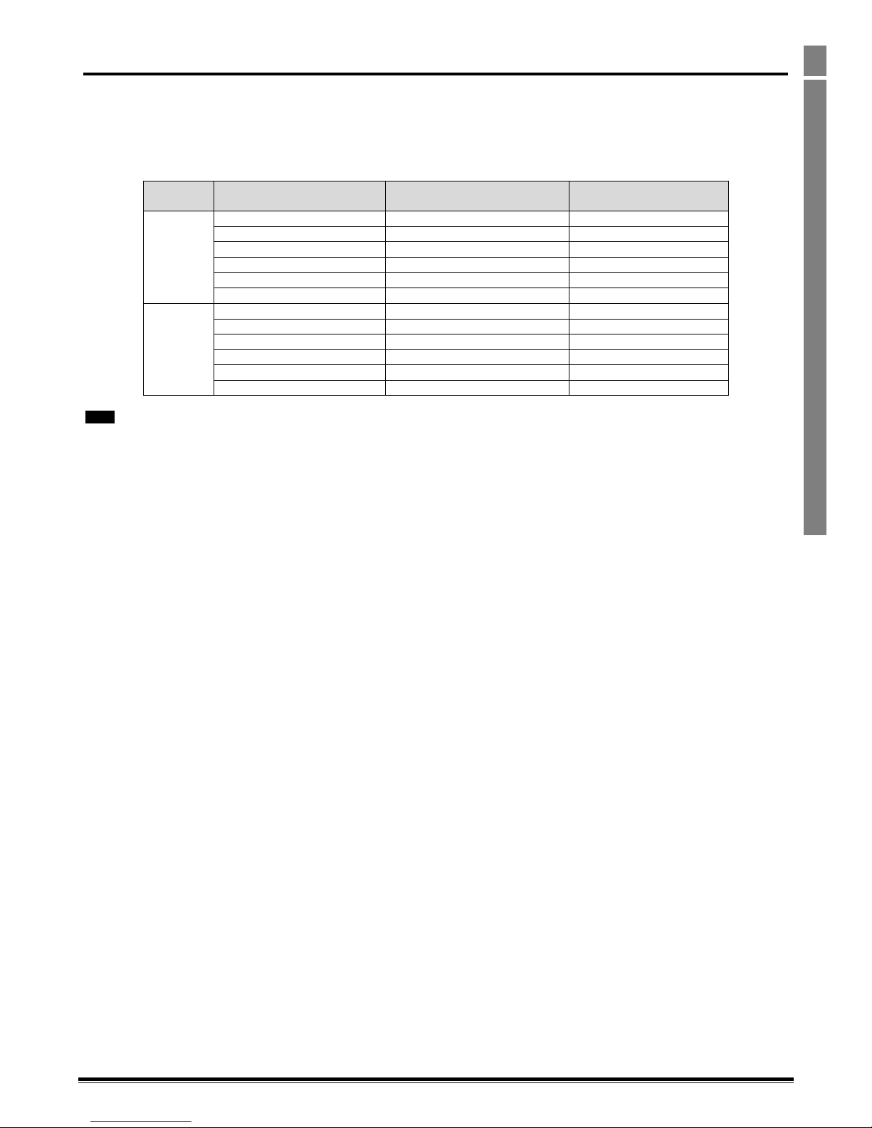
Optidrive P2 Advanced User Guide Revision 2.00
www.invertekdrives.com
59
Rated Temperatures and De-rating curves
6
6. Rated Temperatures and De-rating curves
6.1. Thermal Management
The Optidrive P2 product range has an integrated Thermal Management function. This function allows the drive to automatically reduce the
effective switching frequency when operating at higher heatsink temperatures to avoid the risk of an over temperature trip. The value set in
the Thermal Management parameter (P6-02) determines the lowest switching frequency the drive is permitted to automatically reduce to.
Table 1 below shows the heatsink temperature threshold points at which thermal management occurs.
Supply
Voltage
Effective Switching Frequency
(Where Supported)
Temperature Limit for Switching
Frequency Redcution
Temperature Limit for Over
Temperature Trip
230 & 400
32kHz
70ᵒC
80ᵒC
24kHz
75ᵒC
83ᵒC
16kHz
80ᵒC
86ᵒC
12kHz
85ᵒC
89ᵒC
8kHz
90ᵒC
92ᵒC
4kHz
N/A
95ᵒC
600
32kHz
70ᵒC
75ᵒC
24kHz
75ᵒC
79ᵒC
16kHz
80ᵒC
83ᵒC
12kHz
85ᵒC
87ᵒC
8kHz
90ᵒC
91ᵒC
4kHz
N/A
95ᵒC
NOTE
The available range of switching frequencies is subject to the drive frame size, power rating and voltage rating.
6.2. De-rating Curves Explained
The following de-rating curves each show the maximum continuous output current against drive heatsink temperature. In each graph the
curves represent the performance of the largest rated drive for that frame size and rated voltage for each available switching frequency.
Where lower power rating variants are available their limits are shown as dotted lines to intersect the curves.
Page 60
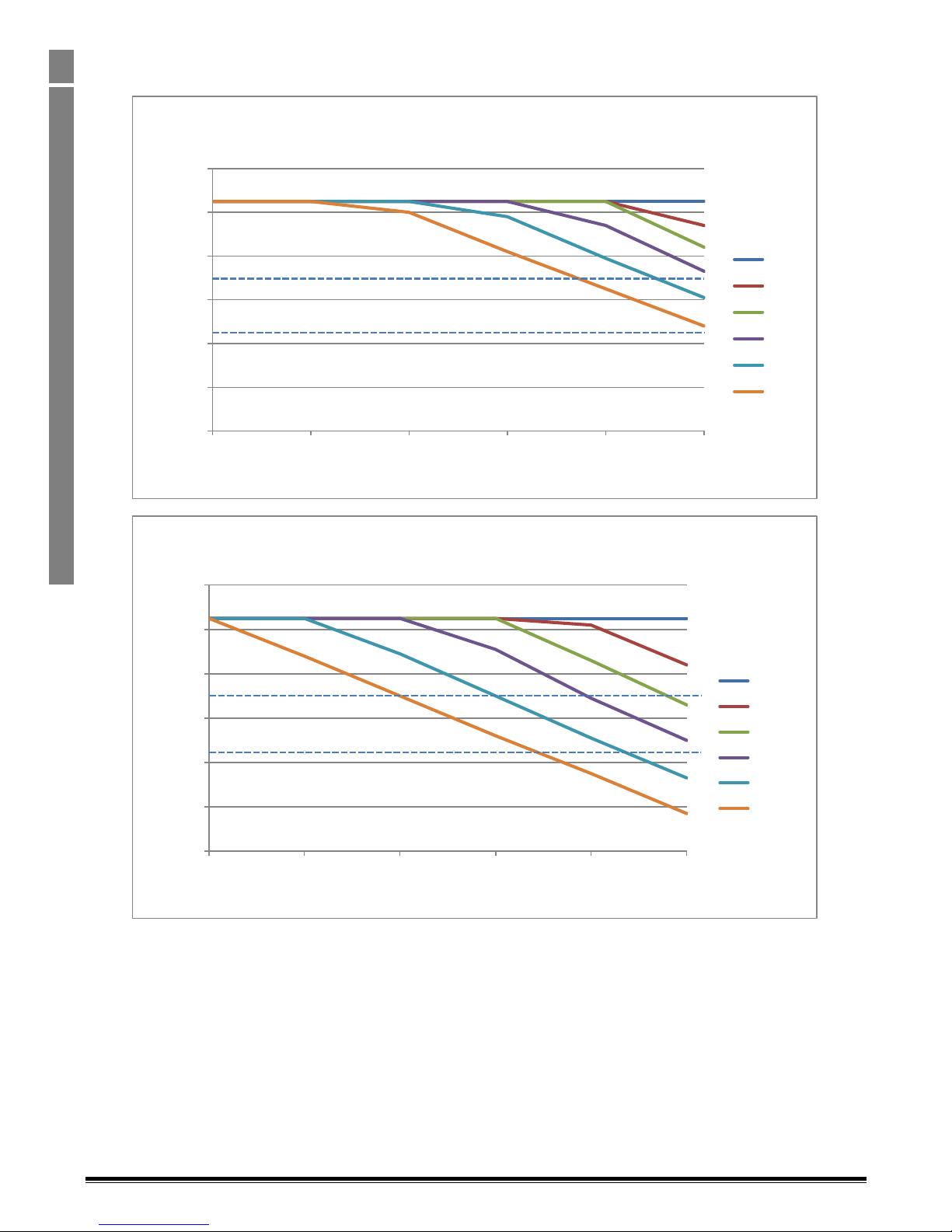
Optidrive P2 Advanced User Guide Revision 2.00
60
www.invertekdrives.com
Rated Temperatures and De-rating curves
6
6.3. Size 2, 200-240V
6.3.1. 4.3A, 7A & 10.5A Output, IP20
0.0
2.0
4.0
6.0
8.0
10.0
12.0
0 10 20 30 40 50
Output Curremt (A)
Ambient Temperature (°C)
ODP-2, Size 2, 220V, 2.2kW, IP20 Drive
De-rating - Without Thermal Managment
4kHz
8kHz
12kHz
16kHz
24kHz
32kHz
0.0
2.0
4.0
6.0
8.0
10.0
12.0
0 10 20 30 40 50
Output Curremt (A)
Ambient Temperature (°C)
ODP-2, Size 2, 220V, 2.2kW, IP20 Drive
De-rating - With Thermal Managment
4kHz
8kHz
12kHz
16kHz
24kHz
32kHz
Page 61
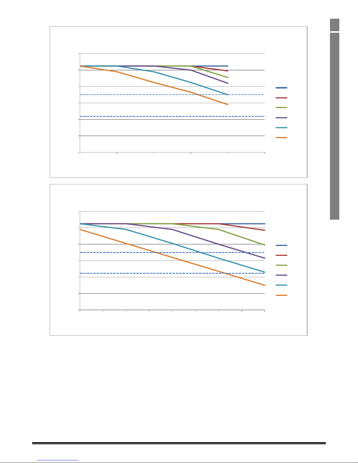
Optidrive P2 Advanced User Guide Revision 2.00
www.invertekdrives.com
61
Rated Temperatures and De-rating curves
6
6.3.2. 4.3A, 7A & 10.5A Output, IP66
0.0
2.0
4.0
6.0
8.0
10.0
12.0
0 10 20 30 40 50
Output Curremt (A)
Ambient Temperature (°C)
ODP-2, Size 2, 220V, 2.2kW, IP66 Drive
De-rating - Without Thermal Managment
4kHz
8kHz
12kHz
16kHz
24kHz
32kHz
0.0
2.0
4.0
6.0
8.0
10.0
12.0
0 5 10 15 20 25 30 35 40
Output Curremt (A)
Ambient Temperature (°C)
ODP-2, Size 2, 220V, 2.2kW, IP66 Drive
De-rating - With Thermal Managment
4kHz
8kHz
12kHz
16kHz
24kHz
32kHz
Page 62
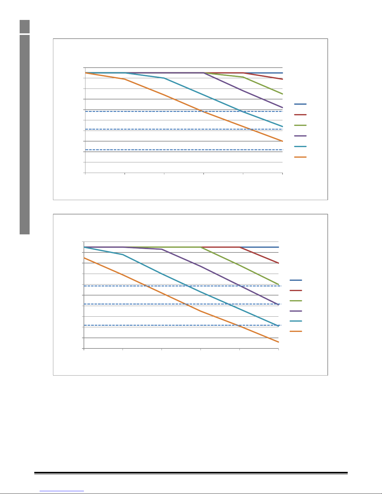
Optidrive P2 Advanced User Guide Revision 2.00
62
www.invertekdrives.com
Rated Temperatures and De-rating curves
6
6.4. Size 2, 380-480V
6.4.1. 2.2A, 4.1A, 5.8A, 9.5A Output, IP20
0.0
1.0
2.0
3.0
4.0
5.0
6.0
7.0
8.0
9.0
10.0
0 10 20 30 40 50
Output Curremt (A)
Ambient Temperature (°C)
ODP-2, Size 2, 400V, 4kW , IP20 Drive
De-rating - Without Thermal Managment
4kHz
8kHz
12kHz
16kHz
24kHz
32kHz
0.0
1.0
2.0
3.0
4.0
5.0
6.0
7.0
8.0
9.0
10.0
0 10 20 30 40 50
Output Curremt (A)
Ambient Temperature (°C)
ODP-2, Size 2, 400V, 4kW, IP20 Drive
De-rating - With Thermal Managment
4kHz
8kHz
12kHz
16kHz
24kHz
32kHz
Page 63
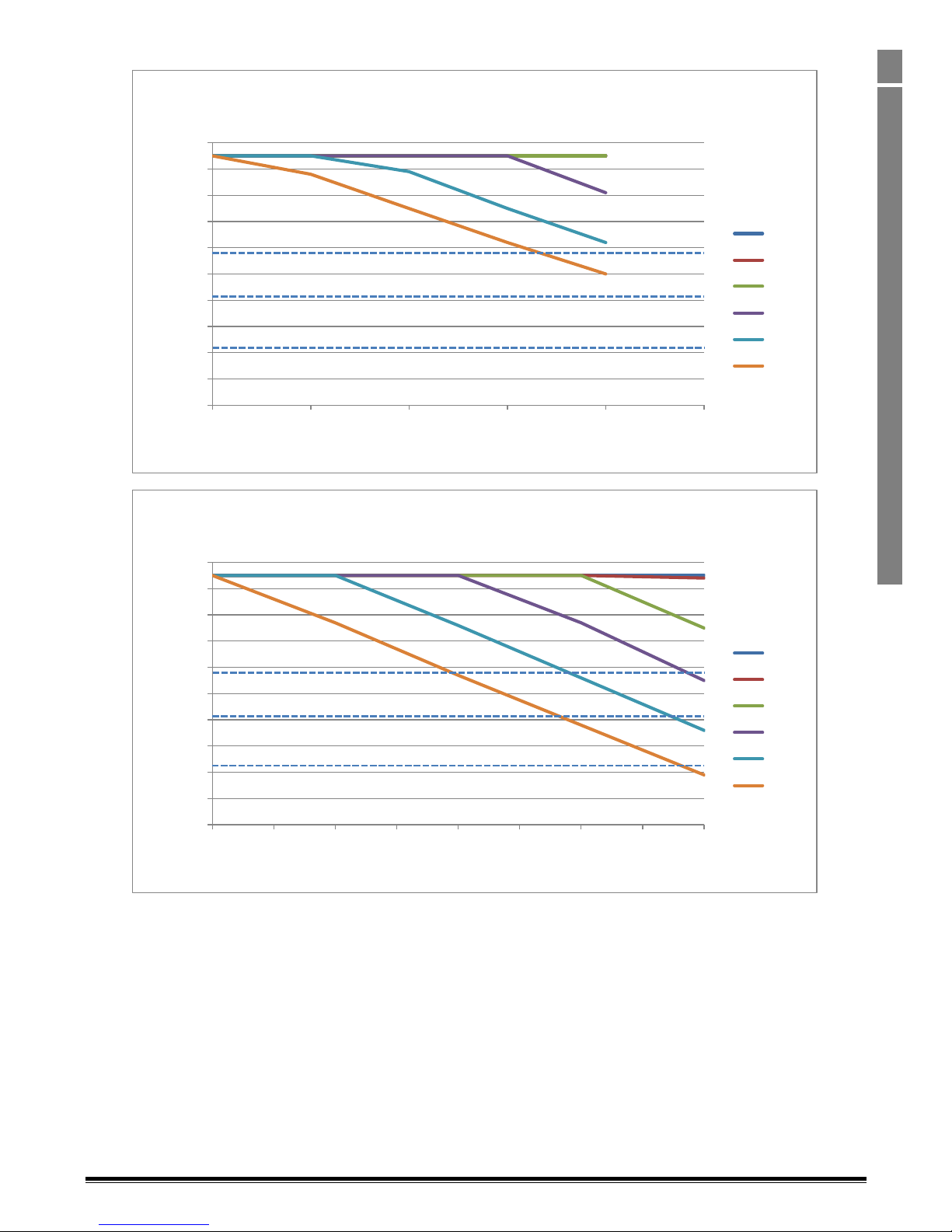
Optidrive P2 Advanced User Guide Revision 2.00
www.invertekdrives.com
63
Rated Temperatures and De-rating curves
6
6.4.2. 2.2A, 4.1A, 5.8A, 9.5A Output, IP66
0.0
1.0
2.0
3.0
4.0
5.0
6.0
7.0
8.0
9.0
10.0
0 10 20 30 40 50
Output Curremt (A)
Ambient Temperature (°C)
ODP-2, Size 2, 400V, 4kW, IP66 Drive
De-rating - Without Thermal Managment
4kHz
8kHz
12kHz
16kHz
24kHz
32kHz
0.0
1.0
2.0
3.0
4.0
5.0
6.0
7.0
8.0
9.0
10.0
0 5 10 15 20 25 30 35 40
Output Curremt (A)
Ambient Temperature (°C)
ODP-2, Size 2, 400V, 4kW, IP66 Drive
De-rating - With Thermal Managment
4kHz
8kHz
12kHz
16kHz
24kHz
32kHz
Page 64
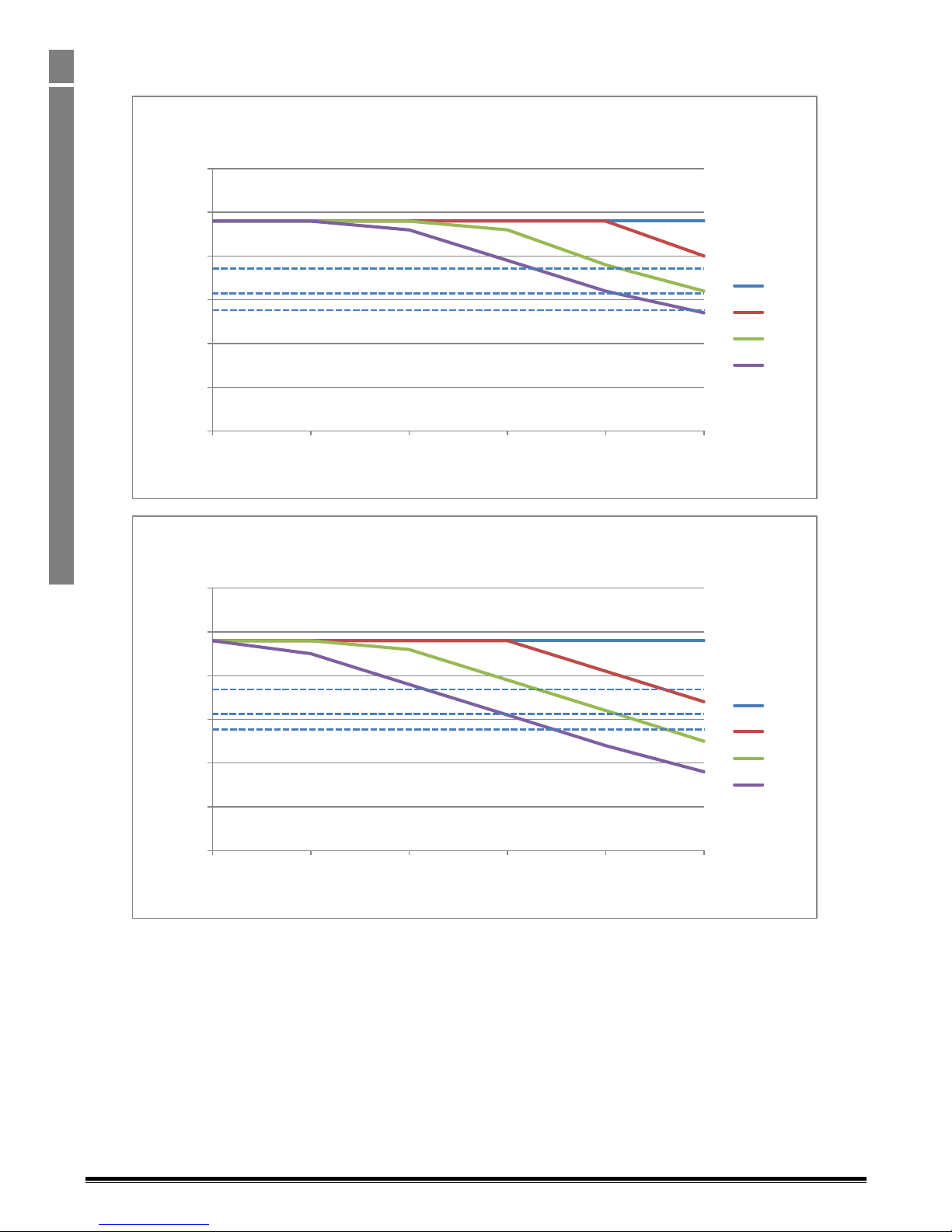
Optidrive P2 Advanced User Guide Revision 2.00
64
www.invertekdrives.com
Rated Temperatures and De-rating curves
6
6.5. Size 3, 200-240V & 380 – 480V
6.5.1. 14A, 15.3A, 18A & 24A Output , IP20
0.0
5.0
10.0
15.0
20.0
25.0
30.0
0 10 20 30 40 50
Output Curremt (A)
Ambient Temperature (°C)
ODP-2, Size 3, 400V, 11kW Drive
De-rating - Without Thermal Managment
4kHz
8kHz
12kHz
16kHz
0.0
5.0
10.0
15.0
20.0
25.0
30.0
0 10 20 30 40 50
Output Curremt (A)
Ambient Temperature (°C)
ODP-2, Size 3, 400V, 11kW Drive
De-rating - With Thermal Managment
4kHz
8kHz
12kHz
16kHz
Page 65
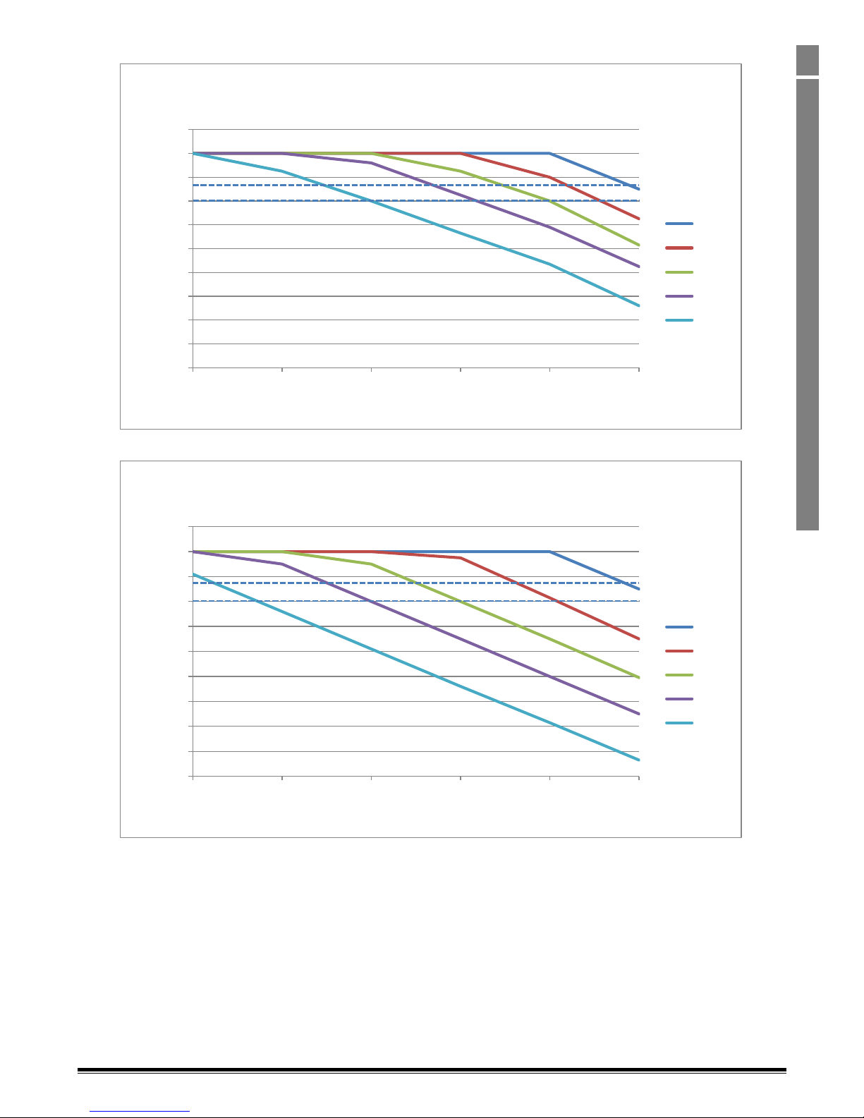
Optidrive P2 Advanced User Guide Revision 2.00
www.invertekdrives.com
65
Rated Temperatures and De-rating curves
6
6.5.2. 14A, 15.3A, & 18A Output , IP66
0.0
2.0
4.0
6.0
8.0
10.0
12.0
14.0
16.0
18.0
20.0
0 10 20 30 40 50
Output Curremt (A)
Ambient Temperature (°C)
ODP-2, Size 3, 400V, 7.5kW Drive
De-rating - Without Thermal Managment
4kHz
8kHz
12kHz
16kHz
24kHz
0.0
2.0
4.0
6.0
8.0
10.0
12.0
14.0
16.0
18.0
20.0
0 10 20 30 40 50
Output Curremt (A)
Ambient Temperature (°C)
ODP-2, Size 3, 400V, 4kW Drive
De-rating - With Thermal Managment
4kHz
8kHz
12kHz
16kHz
24kHz
Page 66
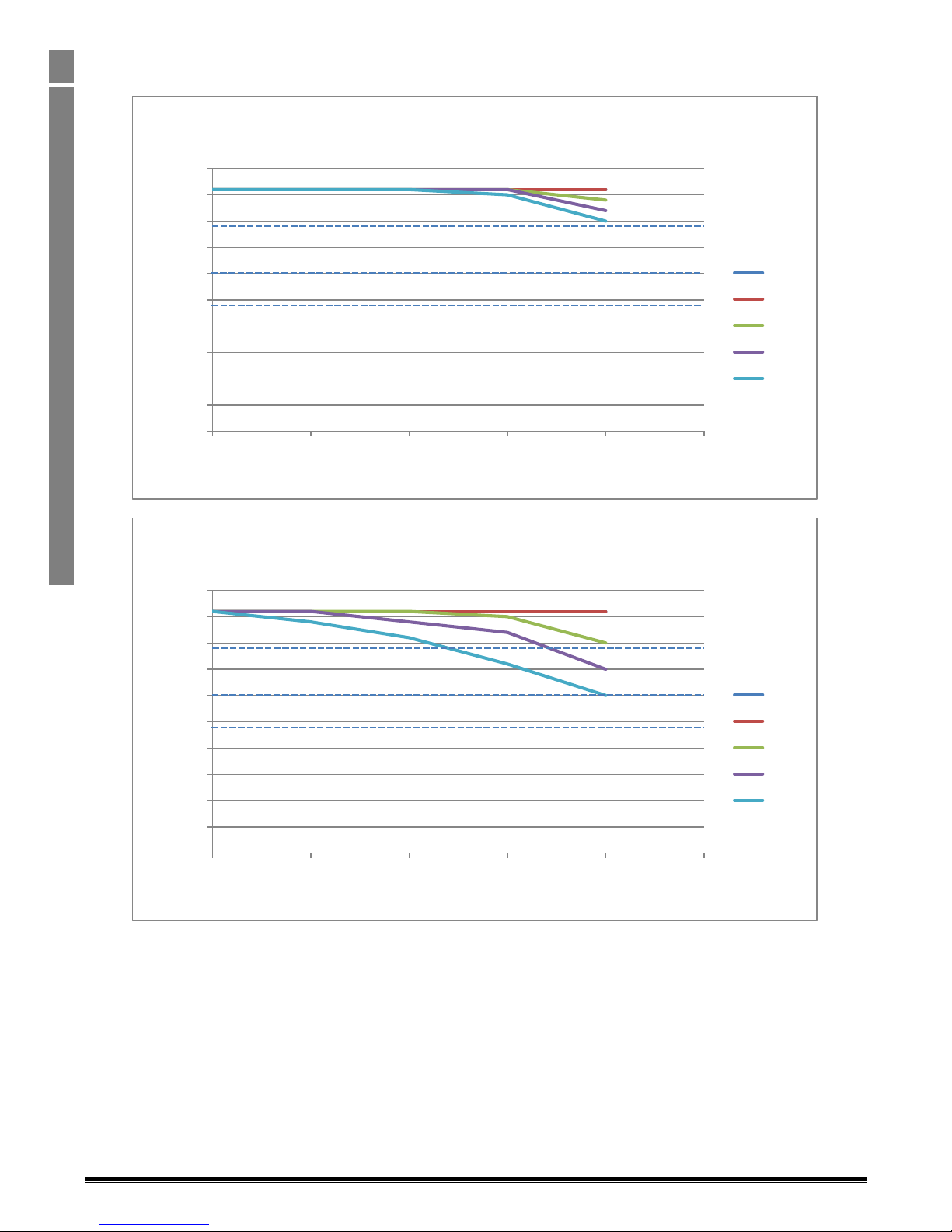
Optidrive P2 Advanced User Guide Revision 2.00
66
www.invertekdrives.com
Rated Temperatures and De-rating curves
6
6.6. Size 4, 200 – 240V & 380-480V,
6.6.1. 24A, 30A, 39A & 46A, IP55
0.0
5.0
10.0
15.0
20.0
25.0
30.0
35.0
40.0
45.0
50.0
0 10 20 30 40 50
Output Curremt (A)
Ambient Temperature (°C)
ODP-2, Size 4, 400V, 22kW Drive
De-rating - Without Thermal Managment
4kHz
8kHz
12kHz
16kHz
24kHz
0.0
5.0
10.0
15.0
20.0
25.0
30.0
35.0
40.0
45.0
50.0
0 10 20 30 40 50
Output Curremt (A)
Ambient Temperature (°C)
ODP-2, Size 4, 400V, 22kW Drive
De-rating - With Thermal Managment
4kHz
8kHz
12kHz
16kHz
24kHz
Page 67
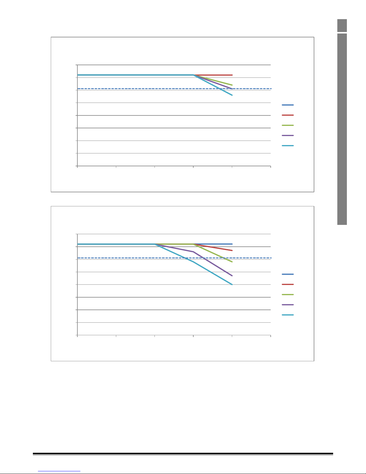
Optidrive P2 Advanced User Guide Revision 2.00
www.invertekdrives.com
67
Rated Temperatures and De-rating curves
6
6.7. Size 5, 200 – 240V & 380-480V,
6.7.1. 61A & 72A Output, IP55
0
10
20
30
40
50
60
70
80
0 10 20 30 40 50
Output Curremt (A)
Ambient Temperature (°C)
ODP-2, Size 5, 400V, 37kW, IP55 Drive
De-rating - Without Thermal Managment
4kHz
8kHz
12kHz
16kHz
24kHz
0
10
20
30
40
50
60
70
80
0 10 20 30 40 50
Output Curremt (A)
Ambient Temperature (°C)
ODP-2, Size 5, 400V, 37kW, IP55 Drive
De-rating - With Thermal Managment
4kHz
8kHz
12kHz
16kHz
24kHz
Page 68
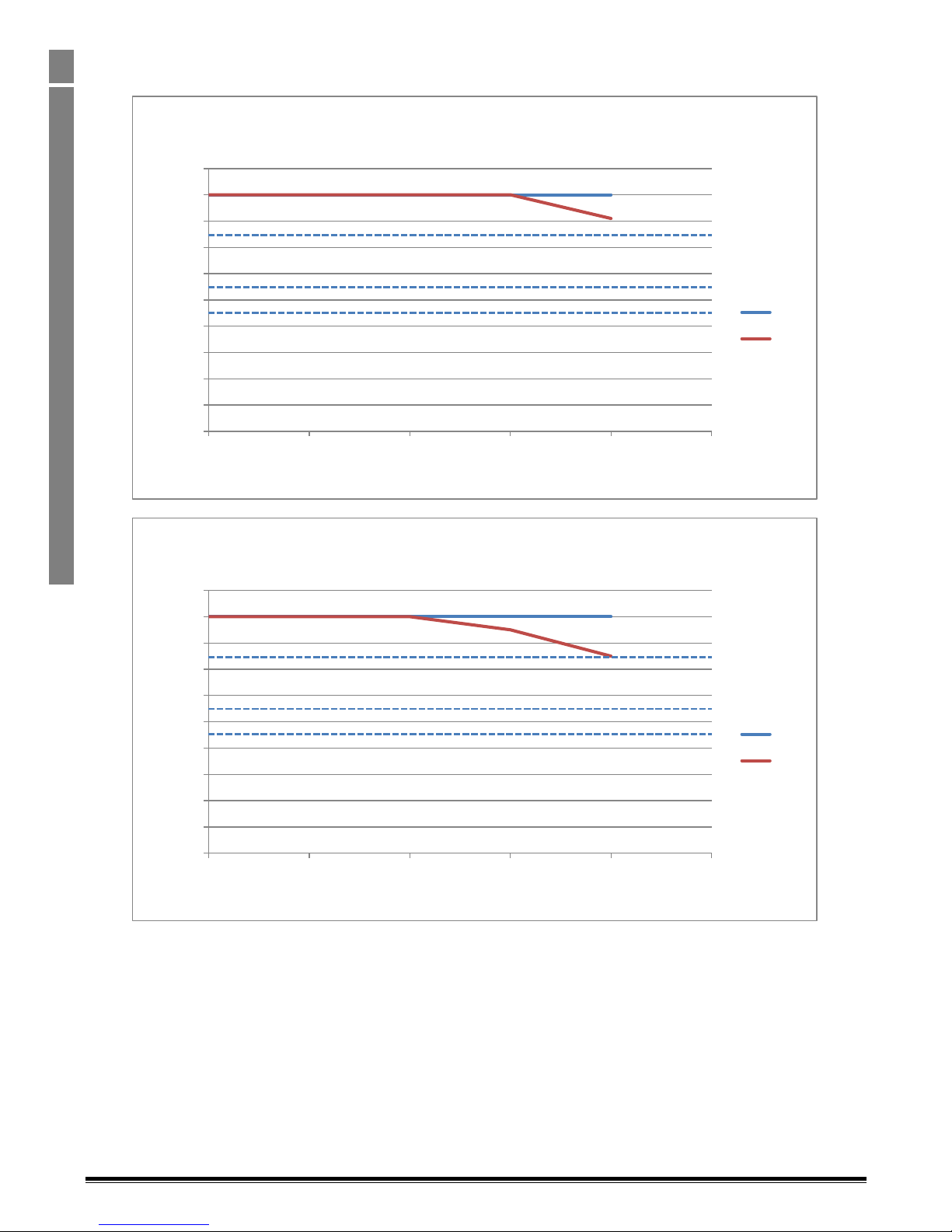
Optidrive P2 Advanced User Guide Revision 2.00
68
www.invertekdrives.com
Rated Temperatures and De-rating curves
6
6.8. Size 6, 200 – 240V & 380-480V,
6.8.1. 90A, 110A, 150A & 180A Output, IP55
0
20
40
60
80
100
120
140
160
180
200
0 10 20 30 40 50
Output Curremt (A)
Ambient Temperature (°C)
ODP-2, Size 6, 400V, 90kW Drive, IP55
De-rating - Without Thermal Managment
4kHz
8kHz
0
20
40
60
80
100
120
140
160
180
200
0 10 20 30 40 50
Output Curremt (A)
Ambient Temperature (°C)
ODP-2, Size 6, 400V, 90kW Drive, IP55
De-rating - With Thermal Managment
4kHz
8kHz
Page 69
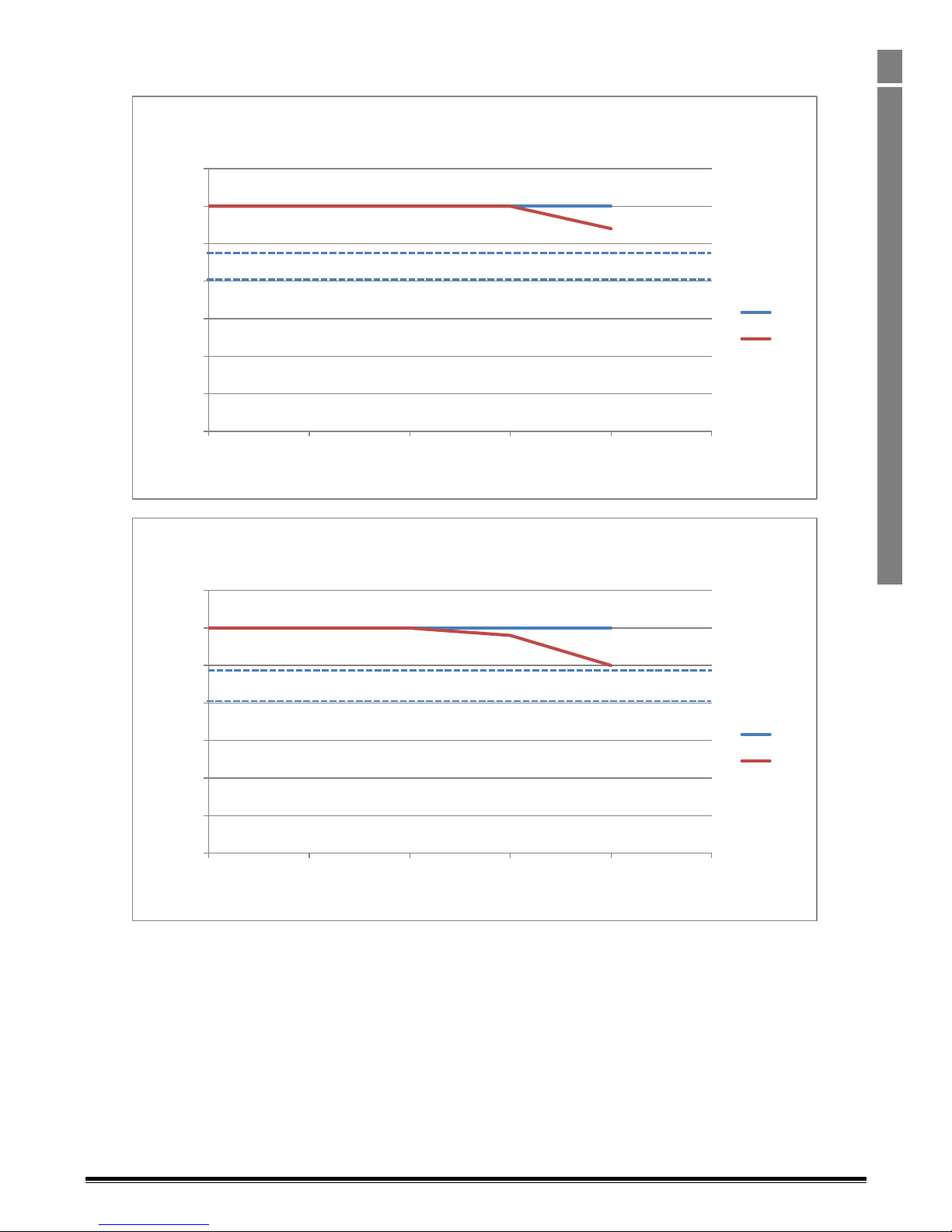
Optidrive P2 Advanced User Guide Revision 2.00
www.invertekdrives.com
69
Rated Temperatures and De-rating curves
6
6.9. Size 7, 200 – 240V & 380-480V,
6.9.1. 202A, 240A, 302A Output, IP55
0
50
100
150
200
250
300
350
0 10 20 30 40 50
Output Curremt (A)
Ambient Temperature (°C)
ODP-2, Size 7, 400V, 160kW Drive, IP55
De-rating - Without Thermal Managment
4kHz
8kHz
0
50
100
150
200
250
300
350
0 10 20 30 40 50
Output Curremt (A)
Ambient Temperature (°C)
ODP-2, Size 7, 400V, 160kW Drive, IP55
De-rating - With Thermal Managment
4kHz
8kHz
Page 70
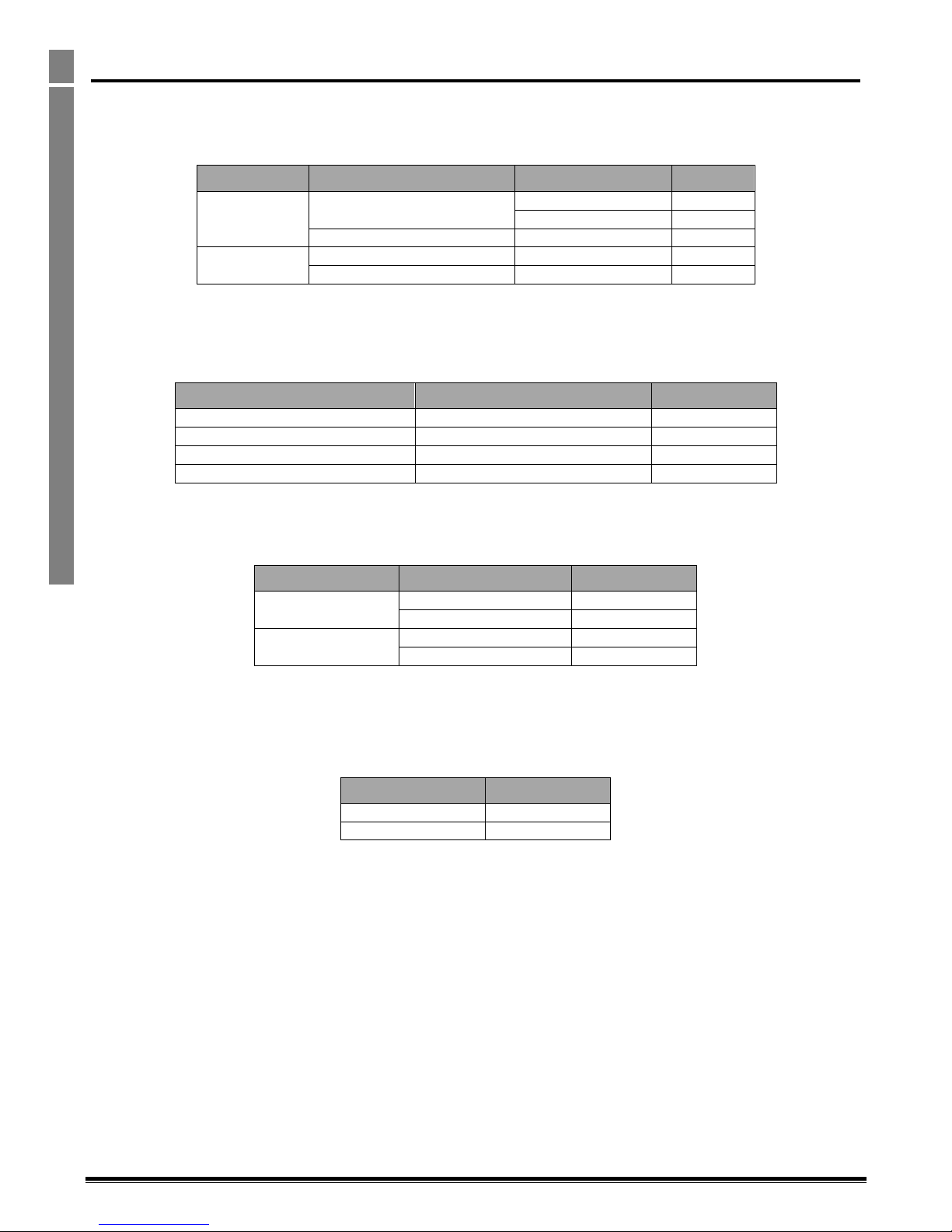
Optidrive P2 Advanced User Guide Revision 2.00
70
www.invertekdrives.com
Immunity Tests
7
7. Immunity Tests
7.1. Electrostatic Discharge (ESD)
The Optidrive P2 and HVAC (ODP-2 and ODV-2) product range have been designed and tested to comply with the limits defined in EN 618003:2004+A1-2012. The test techniques used are as defined in EN 61000-4-2:2009.
Application
Test points
Test Method
Level
Direct
Control Terminals
Contact Discharge
±4kV
Air Discharge
±8kV
Power Terminals
Air Discharge
±8kV
Indirect
Vertical coupling plane
Contact Discharge
±4kV
Horizontal coupling plane
Contact Discharge
±4kV
7.2. Electrical Fast Transient Burst (EFT/B)
The Optidrive P2 and HVAC (ODP-2 and ODV-2) product range have been designed and tested to comply with the limits defined in EN 61800-3:
2004+A1-2012. The test techniques used are as defined in EN 61000-4-4:2004.
Test points
Test Method
Level
Control Terminals
Capacitive clamp
±1kV at 5kHz
Motor Power Terminals
Capacitive clamp
±2kV at 5kHz
1-PH Supply Power Terminals
Coupling Decoupling Network
±2kV at 5kHz
3-PH Supply Power Terminals
Capacitive clamp
±4kV at 5kHz
7.3. Surge
The Optidrive P2 and HVAC (ODP-2 and ODV-2) product range have been designed and tested to comply with the limits defined in EN 61800-3:
2004+A1-2012. The test techniques used are as defined in EN 61000-4-5:2006.
Drive Type
Test Method
Level
200-240V
Line to Line/Neutral
±1kV
Line/Neutral to Earth
±2kV
380-480V
Line to Line
±2kV
Line to Earth
±4kV
7.4. Dielectric strength (Flash)
The Optidrive P2 and HVAC (ODP-2 and ODV-2) product range have been designed and tested to comply with the limits defined in EN 61800-51: 2007. The test techniques used are as defined in EN 61800-5-1: 2007.
Drive Type
Level
200-240V
1.5kV
380-480V
2.5kV
Page 71
Optidrive P2 Advanced User Guide Revision 2.00
www.invertekdrives.com
71
General Technical and Performance Data
8
8. General Technical and Performance Data
8.1. Electrical Data
8.1.1. Mains Supply Details
Supply Voltage Range
230 Volt Units – 200 – 240 Volt +10% / -10%
400 Volt Units – 380 – 480 Volt +10% / -10%
600 Volt Units – 500 – 600 Volt +10% / -10%
Supply Frequency
48 – 62Hz
Inrush Current
< rated input current
Power Up Cycles
>120x /hr, evenly spaced
Single Phase Operation
Three phase drives can be operated from a single phase supply with 50% derating of the maximum output
current
8.1.2. Motor Control
Output Frequency Range
0 to 500Hz in 0.1 Hz steps
High Frequency Option Available, up to 2000Hz depending on model rating. Max Output Frequency = Max
Switching Frequency / 16.
Output Voltage Range
0 to Supply Voltage
Speed Regulation
Open Loop < 2% motor rated speed
Torque Control
0 – 200% of rated torque, + / -5% accuracy, Response time <10ms
Effective Switching Frequency
Refer to section 2.1
Acceleration Time
Four independent acceleration ramps
0 – 600 seconds, 0.01s resolution (Frame 2 & 3)
0 – 6000 seconds, 0.1s resolution (Frame 4 & above)
Deceleration Time
Four individual deceleration ramps
0 – 600 seconds, 0.01s resolution (Frame 2 & 3)
0 – 6000 seconds, 0.1s resolution (Frame 4 & above)
8.1.3. Overload Capacity
Overload Capacity
150% of rated current for 60 seconds, repeat cycle every 10 minutes.
200% / 4 seconds
8.2. Input Output Current Ratings
8.2.1. 230V Input
Frame
Size
Supply
Voltage
Power
Rating
(kW)
Input
Current
(A)
iTHD
(%)
AC
Line
Choke
Input
Current
(A)
iTHD
(%)
Output
Current
(A)
2
230V, 1ph
0.75
8.6
125
OPT-2-L1016-20
4.9 4.3
1.5
12.9
105.8
OPT-2-L1016-20
13.5 7.0
2.2
19.2
97
OPT-2-L1025-20
17.3 10.5
230V, 3ph
0.75
5.7
177.8
OPT-2-L3006-20
4.0
53.6
4.3
1.5
10.5
155.0
OPT-2-L3006-20
6.2
39.4
7.0
2.2
13.2
147.2
OPT-2-L3010-20
9.2
33.1
10.5
3
230V, 3ph
4.0
20.9
115.5
OPT-2-L3036-20
16.0
37.0
18
5.5
26.4
102.7
OPT-2-L3036-20
21.4
33.1
24
4
230V, 3ph
5.5
26.9
117
OPT-2-L3036-20
21.5
33.1
24
7.5
33.3
108
OPT-2-L3036-20
26.9
35.2
30
11
50.1
99.1
OPT-2-L3050-20
40.3
27.6
46
5
230V, 3ph
15
63.9
88
OPT-2-L3090-20
54.2
32.4
61
18.5
74.0
84.8
OPT-2-L3090-20
64
32.4
72
6
230V, 3ph
22
99.1
93.7
OPT-2-L3090-20
86.3
53.6
90
30
121.0
88.8
OPT-2-L3200-00
102.9
47.3
110
37
159.7
77.2
OPT-2-L3200-00
138.3
43.6
150
45
187.5
72.6
OPT-2-L3200-00
164.2
37
180
7
230V, 3ph
55
206.5
57.5
OPT-2-L3200-00
188.6
43.6
202
75
246.3
50.5
OPT-2-L3300-00
230.8
39.4
248
The data above is provided to show typical values. Results measured at the point of installation may vary according to the installation site and
load conditions Test results are measured under the following conditions :-
230 Volt RMS AC Supply Voltage
Operating IE2 motor with matching power rating according to the drive
Operated at full rated output current capacity
Page 72
Optidrive P2 Advanced User Guide Revision 2.00
72
www.invertekdrives.com
General Technical and Performance Data
8
8.2.2. 400 / 460 Volt Input
Frame
Size
Supply
Voltage
Power
Rating
(kW)
Input
Current
(A)
iTHD
(%)
AC
Line
Choke
Input
Current
(A)
iTHD
(%)
Output
Current
(A)
2
400V, 3ph
0.75
3.5
177.8
OPT-2-L3006-20
2.7
92.5
2.2
1.5
5.6
155.0
OPT-2-L3006-20
4.5
64.5
4.1
2.2
7.5
147.2
OPT-2-L3006-20
5.5
64.5
5.8
4.0
11.5
124.3
OPT-2-L3010-20
8.9
47.3
9.5
3
400V, 3ph
5.5
17.2
126.3
OPT-2-L3036-20
14.5
53.6
14
7.5
21.8
115.5
OPT-2-L3036-20
17.7
47.3
18
11
27.5
102.7
OPT-2-L3036-20
21.9
43.6
24
4
400V, 3ph
11
28.0
117.0
OPT-2-L3036-20
21.9
43.6
24
15
34.2
108.0
OPT-2-L3036-20
28.1
47.3
30
18.5
44.1
104.0
OPT-2-L3050-20
35.4
39.4
39
22
51.9
99.1
OPT-2-L3050-20
41.5
37
46
5
400V, 3ph
30
66.1
84.8
OPT-2-L3090-20
56.3
43.6
61
37
77.3
88.8
OPT-2-L3090-20
65.4
39.4
72
6
400V, 3ph
45
102.7
93.8
OPT-2-L3090-20
91.6
64.5
90
55
126.4
88.8
OPT-2-L3200-00
112
64.5
110
75
164.7
77.2
OPT-2-L3200-00
147.4
53.6
150
90
192.1
72.6
OPT-2-L3200-00
172.4
47.3
180
7
400V, 3ph
110
210.8
57.5
OPT-2-L3200-00
208.1
64.5
202
132
241.0
50.5
OPT-2-L3300-00
238.6
53.6
240
160
299.0
44.8
OPT-2-L3300-00
296.2
47.3
302
8
400V, 3ph
200
377.2
56.3
OPT-2-L3500-00
376.6
42.1
370
250
458.7
56.3
OPT-2-L34500-00
429.4
42.1
450
The data above is provided to show typical values. Results measured at the point of installation may vary according to the installation site and
load conditions Test results are measured under the following conditions :-
400 Volt RMS AC Supply Voltage
Operating IE2 motor with matching power rating according to the drive
Operated at full rated output current capacity
Page 73
Optidrive P2 Advanced User Guide Revision 2.00
www.invertekdrives.com
73
General Technical and Performance Data
8
8.2.3. 525 Volt Input
Frame
Size
Supply
Voltage
Power
Rating
(kW)
Input
Current
(A)
iTHD
(%)
AC
Line
Choke
Input
Current
(A)
iTHD
(%)
Output
Current
(A)
7
525V, 3ph
132
191.9
57.5
N/A
N/A
N/A
185
160
214.9
50.5
N/A
N/A
N/A
205
185
261.7
44.8
N/A
N/A
N/A
255
200
275.3
43.2
N/A
N/A
N/A
275
The data above is provided to show typical values. Results measured at the point of installation may vary according to the installation site and
load conditions Test results are measured under the following conditions :-
525 Volt RMS AC Supply Voltage
Operating IE2 motor with matching power rating according to the drive
Operated at full rated output current capacity
8.2.4. 575 Volt Input
Frame
Size
Supply
Voltage
Power
Rating
(kW)
Input
Current
(A)
iTHD
(%)
AC
Line
Choke
Input
Current
(A)
iTHD
(%)
Output
Current
(A)
2
575V, 3ph
0.75
3.4
N/A
N/A
N/A
N/A
2.1
1.5
4.2
N/A
N/A
N/A
N/A
3.1
2.2
4.9
N/A
N/A
N/A
N/A
4.1
4.0
8.6
N/A
N/A
N/A
N/A
6.5
5.5
12.2
N/A
N/A
N/A
N/A
9
3
575V, 3ph
7.5
15.1
N/A
N/A
N/A
N/A
12
11
20.9
N/A
N/A
N/A
N/A
17
15
25.5
N/A
N/A
N/A
N/A
22
4
575V, 3ph
15
26.0
N/A
N/A
N/A
N/A
22
18.5
32.2
N/A
N/A
N/A
N/A
28
22
39.1
N/A
N/A
N/A
N/A
34
30
48.9
N/A
N/A
N/A
N/A
43
5
575V, 3ph
37
59.5
N/A
N/A
N/A
N/A
54
45
70.4
N/A
N/A
N/A
N/A
65
6
575V, 3ph
55
90.6
N/A
N/A
N/A
N/A
78
75
121.1
N/A
N/A
N/A
N/A
105
90
143.2
N/A
N/A
N/A
N/A
130
110
158.4
N/A
N/A
N/A
N/A
150
The data above is provided to show typical values. Results measured at the point of installation may vary according to the installation site and
load conditions Test results are measured under the following conditions :-
575 Volt RMS AC Supply
Operating IE2 motor with matching power rating according to the drive
Operated at full rated output current capacity
Page 74
Optidrive P2 Advanced User Guide Revision 2.00
74
www.invertekdrives.com
General Technical and Performance Data
8
8.3. Standby Power Consumption
The following table shows the power consumption of the drive under the following conditions.
Minimum – Value measured when the drive is powered from the nominal rated mains supply voltage (e.g. 230 or 400 Volt), output disabled,
cooling fan off, and no external power drawn from the control terminals
Maximum – Maximum value with cooling fan operating, 24V, 100mA load on the control terminals
Frame Size
Voltage
Minimum
Maximum
2
230 8
400
10
40
600
3
230 8
400
11
50
600 4 230
11
400
16.7
60
600 5 230
400
19.8
70
600
6
230
400
31.1
96
600 7 230
400
38.5
105 8 400
8.4. DC Bus Discharge Time
DC Bus discharge times are based on maximum rated DC bus, i.e. 480Vac +10% AC supply equates to a DC Bus voltage of 746Vdc within the
drive.
In compliance with EN 61800-5-1:2007, all drives have a caution on the rating labels stating “Power down for 5 minutes before removing
cover”
Frame
Size
Supply
Voltage
DC Bus Voltage
Time to
reach 50V
Max
after 5s
after 60s
2
240Vac +10%
375
324
53
75 sec
480Vac +10%
746
621
64
86 sec
3
240Vac +10%
375
326
40
30 sec
480Vac +10%
746
625
73
120 sec
4
480Vac +10%
746
685
98
182 sec
5
480Vac +10%
746
671
99
179 sec
6
480Vac +10%
746
703
246
181 sec
7
480Vac +10%
746
701
343
190 sec
Page 75
Optidrive P2 Advanced User Guide Revision 2.00
www.invertekdrives.com
75
General Technical and Performance Data
8
8.5. Earth Leakage Current (Touch Current)
The Optidrive P2 and HVAC (ODP-2 and ODV-2) product range have been designed and tested to comply with the limits defined in EN 61800-51: 2007. The test techniques used are as defined in EN 60990:2000.
As stated in the standard 61800-5-1:2007, 5.2.3.5 the motor does not have to be loaded, however, the motor type, cable type and length can
have a significant impact on the results. For the purpose of testing and test repeatability Invertek use the following motor:-
Manufacture:
SEW
Model:
DT90L4/ES1T
Type:
Induction motor
Pole:
4
Cable:
1.5m, 2.5mm2, Type - YY
Frame
Size
Typical Supply Conditions
Maximum Supply Conditions
Supply Voltage
I
Touch
(mA)
Supply Voltage
I
Touch
(mA)
2
1ph 230V 50Hz
2.49
1ph 240V +10% 60Hz
3.28
3ph 230V 50Hz
1.73
3ph 240V +10% 60Hz
2.73
3ph 400V 50Hz
4.65
3ph 480V +10% 60Hz
7.37
3
3ph 230V 50Hz
0.93
3ph 240V +10% 60Hz
1.34
3ph 400V 50Hz
1.55
3ph 480V +10% 60Hz
2.45
4
3ph 230Vac 50Hz
1.42
3ph 240V +10% 60Hz
2.24
3ph 400Vac 50Hz
2.47
3ph 480V +10% 60Hz
3.90
5
3ph 230Vac 50Hz
0.28
3ph 240V +10% 60Hz
0.44
3ph 400Vac 50Hz
0.49
3ph 480V +10% 60Hz
0.77
6
3ph 230Vac 50Hz
1.54
3ph 240V +10% 60Hz
2.43
3ph 400Vac 50Hz
2.68
3ph 480V +10% 60Hz
4.23
7
3ph 230Vac 50Hz
2.74
3ph 240V +10% 60Hz
4.33
3ph 400Vac 50Hz
4.75
3ph 480V +10% 60Hz
7.51
NOTE
The Touch Current value is based on:-
Normal operating conditions, i.e. all phases balanced and connected correctly with the motor running
Drive fitted with integrated EMC filter
Page 76

Optidrive P2 Advanced User Guide Revision 2.00
76
www.invertekdrives.com
General Technical and Performance Data
8
8.6. Digital & Analog I/O
8.6.1. Digital Inputs Specification
Voltage Range 8 – 30 V dc, Internal or External supply, NPN (positive logic)
Response Time < 8ms
8.6.2. Inhibit (Safe) Input
Voltage Range Inhibit input 18 – 30V dc
Response Time Inhibit input < 100us for shutdown
8.6.3. Analog Inputs Specification
Range Current : 0-20mA, 4-20mA. 20mA max input current
Voltage: -10-10V (Analog Input 1 Only), 0-10V, 0-5V, 0/24V, 30V max input
Resolution Analog Input 1: 12-bit + sign, <16ms response time (bipolar)
Analog Input 2: 12-bit, <16ms response time (Uni-Polar)
Accuracy better than 1% of full scale
Scaling & Offset Parameter adjustable
8.6.4. Analog Outputs Specification
Range Current : 0..20mA, 4..20mA, 20mA max
Analog : 0..10V, 0 / 24V (digital), 20mA max
Resolution 10-bit
Accuracy better than 1% of full scale
8.6.5. Relay Outputs (1x N.O, 1x C.O)
Maximum Switching Voltage : 250VAC, 30 VDC
Maximum Switching Current : 5A at 30 Volt DC, 6A at 250 Volt AC
Page 77
Optidrive P2 Advanced User Guide Revision 2.00
www.invertekdrives.com
77
General Technical and Performance Data
8
8.7. Environmental Data
8.7.1. Temperature Range
Ambient Temperature Range : Operation
IP20 Drives : -10 - +50°C (14 - 122°F) without derating
IP55 & IP66 Drives : -10 - + 40°C (14 - 104°F) without derating
Note : No frost or condensation permissible
Ambient Temperature Range : Storage
-40 … 60 ºC. No Frost or Condensation
8.7.2. Altitude
Maximum Altitude (No derating)
1000m Derate above 1000m by 1% per 100m
Maximum Altitude (UL Approved)
2000m
Maximum Altitude
4000m
8.7.3. Relative Humidity
Relative Humidity Limit
95% Maximum, non-condensing
8.7.4. Contamination Levels
Standard
IEC 721-3-3, Non-conductive dust allowed
Transportation
Class 1C2 (chemical gases),
Class 1S2 (solid particles)
Storage
Class 2C2 (chemical gases),
Class 2S2 (solid particles)
Operation
Class 3C2 (chemical gases),
Class 3S2 (solid particles
8.7.5. Vibration Levels
Bump Test
Testing in each of three mutually perpendicular axes in turn.
Reference standard: IEC 60068-2-29
Severity: 18g, 6ms, half sine
No of bumps: 600 (100 per axis)
Random Vibration Test
Testing in each of three mutually perpendicular axes in turn.
Reference standard: IEC 60068-2-64
Severity: 1.0m2/s3 (0.01 g2/Hz) ASD from 5-20Hz -3dB/octave from 20 to 200Hz
Duration: 30 minutes in each of 3 mutually perpendicular axes.
Sinusoidal vibration test
Testing in each of three mutually perpendicular axes in turn.
Reference standard: IEC 60068-2-6
Frequency range: 2-500Hz
Severity: 3.5mm peak displacement from 2 to 9Hz
10 m/s2 peak acceleration from 9 to 200Hz
15 m/s2 peak acceleration from 200 to 500Hz
Sweep rate: 1 octave/minute
Duration: 15 minutes in each of 3 mutually perpendicular axes.
8.8. Response Times
Command Source
Response Time
STO Input
<25ms
Digital Input
<8ms
Analog Input
<16ms
Modbus RTU Interface
<8ms From receipt of valid command
CAN Open Interface
<8ms From receipt of valid command
Extended I/O Option
<8ms
Plug In Fieldbus Option
<20ms + Fieldbus Cycle Time From receipt of valid command
Master / Slave Function
<8ms, response, 60ms cycle
Power Stage
<10ms to enable output
8.9. Motor Control Performance
8.9.1. Enhanced V/F Mode
Speed Regulation : + / - 20% of motor slip with slip compensation enabled
8.9.2. 3GV Vector Mode without Encoder Feedback
Static Speed Regulation : + / - 0.033%
Speed Regulation 0 – 200% Load Range : + / - 0.5%
Torque Response : 1- 8ms
Torque Linearity (10 – 90% of motor rated speed, 20 – 100% load torque range) : + / - ???%
8.9.1. 3GV Vector Mode with Encoder Feedback
Static Speed Regulation : + / - 0.033%
Speed Regulation 0 – 200% Load Range : + / - 0.033%
Torque Response : 1- 8ms
Torque Linearity (10 – 90% of motor rated speed, 20 – 100% load torque range) : <+ / - 1%
Page 78
Optidrive P2 Advanced User Guide Revision 2.00
78
www.invertekdrives.com
General Technical and Performance Data
8
8.10. Output Current Limit
8.10.1. Overload Operation
Optidrive P2 provides the following
150% Output current / 60 Seconds Maximum
200% Output current / 3.75 Seconds Maximum
At low output frequency levels, overload accumulation is faster, to account for the reduced motor cooling effect of the fan.
8.10.2. Overview
Optidrive P2 features both hardware and software protection of the output stage to prevent damage. In addition, an Ixt system is used to
monitor motor overload condition and prevent damage to the motor due to operation for prolonged periods at high load.
I x t protection is software based, using the value for motor rated current programmed in P1-08. An internal accumulator register is used to
estimate the point at which damage may occur to the motor, and operates as follows
Motor Current < P1-08
The accumulator value reduces towards zero. The time required depends on the actual load current as explained further below.
Motor Current = 100% P1-08
The accumulator value remains static.
Motor Current > 100% P1-08 < 150% P1-08
The accumulator value increases at a rate proportional to the overload level, e.g. (Motor Current / Rated current) – 100%. If the overload limit
is reached, the drive will trip, displaying it.trp. to protect the motor.
Motor Current > 150% P1-08
For high current levels, the accumulator operates 16 times faster than for current levels below 150% of P1-08.
Peak over current trip levels are shown in the table below.
8.10.3. Example Operation
Maximum overload operation is 150% of motor rated current for 60 seconds. As this represents an overload of 50%, the accumulator trip level
is 3000. This means that if the drive operates with 125% load current, the time can be calculated as 3000 / (125 – 100) = 120 Seconds.
Above 150% load, accumulation is 16 times faster, hence for 160% load current, the time is 3000 / 16 / (160 – 150) = 18.75 seconds
8.10.4. Overload Curve
100
110
120
130
140
150
160
170
180
190
200
0 500 1000 1500 2000 2500 3000
Time
Time
Load (%)
Page 79
Optidrive P2 Advanced User Guide Revision 2.00
www.invertekdrives.com
79
General Technical and Performance Data
8
8.10.5. Over Current Trip Level
The following table shows the peak over current trip levels applicable to each model.
Frame Size
Voltage
kW
O-I Trip Level (Default P1-08)
H O-I Trip Level
2
230
0.75
14A
34.3A
1.5
20A
34.3A
2.2
30A
34.3A
400
0.75
7A
34.3A
1.5
12A
34.3A
2.2
17A
34.3A 4 27A
34.3A
600
0.75
7A
34.3A
1.5
10A
34.3A
2.2
14A
34.3A 4 17A
34.3A
5.5
26A
34.3A
3
230
4
55A
64A
5.5
70A
70A
400
5.5
45A
64A
7.5
55A
64A
11
70A
70A
600
7.5
45A
70A
11
55A
70A
15
70A
70A
4
230
5.5
70A
148A
7.5
85A
148A
11
120A
148A
400
11
70A
148A
15
90A
148A
18.5
110A
148A
22
120A
148A
600
15
90A
148A
18.5
100A
148A
22
110A
148A
30
120A
148A
5
230
15
180A
258A
18.5
180A
258A
400
30
180A
258A
37
180A
258A
600
37
180A
258A
45
180A
258A
6
230
22
225A
258A
30
320A
381A
37
425A
516A
45
450A
516A
400
45
225A
258A
55
320A
381A
75
425A
516A
90
450A
516A
600
55
225A
258A
75
320A
381A
90
425A
516A
110
450A
516A
7
230
55
570A
767A
75
650A
767A
90
700A
767A
400
110
570A
767A
132
650A
767A
160
700A
767A
8
400
200
1000A
1500A
250
1000A
1500A
8.11. Under / Over Voltage Trip Levels
The following levels are not user adjustable, and define the operating voltage levels of the drive and brake chopper circuit.
Drive Rated Supply
Voltage
DC Bus Voltage Level (Volts DC)
Brake Chopper On
Brake Chopper Off
Under Voltage Trip
Minimum Operating
Over Voltage Trip
200 – 240 Volts AC
390
378
160
239
418
380 – 480 Volts AC
780
756
320
474
835
480 – 525 Volts AC
890
862
360
540
930
500 – 600 Volts AC
975
945
400
598
1020
Page 80

Optidrive P2 Advanced User Guide Revision 1.20
80
www.invertekdrives.com
General Technical and Performance Data
8
 Loading...