

INVERTEC V205, V270, V405 Operator's Manual

W83CE285
01/2006
Rev. 4
INVERTEC£ V205, V270 & V405
OPERATOR’S MANUAL
MANUALE OPERATIVO
BEDIENUNGSANLEITUNG
MANUAL DE INSTRUCCIONES
MANUEL D'UTILISATION
BRUKSANVISNING OG DELELISTE
GEBRUIKSAANWIJZING
BRUKSANVISNING
INSTRUKCJA OBSàUGI
KÄYTTÖOHJE
LINCOLN ELECTRIC ITALIA S.r.l
Via Fratelli Canepa 8, 16010 Serrà Riccò (GE), Italia
www.lincolnelectriceurope.com

II
Declaration of conformity
Dichiarazione di conformità
Konformitätserklärung
Declaración de conformidad
Déclaration de conformité
Samsvars erklæring
Verklaring van overeenstemming
Försäkran om överensstämmelse
Deklaracja zgodnoĞci
Vakuutus yhteensopivuudesta
LINCOLN ELECTRIC ITALIA S.r.l.
Declares that the welding machine:
Dichiara che Il generatore per saldatura tipo:
Erklärt, daß die Bauart der Maschine:
Declara que el equipo de soldadura:
Déclare que le poste de soudage:
Bekrefter at denne sveisemaskin:
Verklaart dat de volgende lasmachine:
Försäkrar att svetsomriktaren:
Deklaruje, Īe spawalnicze Ĩródáo energii:
Vakuuttaa, että hitsauskone:
INVERTEC£ V205
conforms to the following directives:
è conforme alle seguenti direttive:
den folgenden Bestimmungen entspricht:
es conforme con las siguientes directivas:
est conforme aux directives suivantes:
er i samsvar med følgende direktiver:
overeenkomt conform de volgende richtlijnen:
överensstämmer med följande direktiv:
speánia nastĊpujące wytyczne:
täyttää seuraavat direktiivit:
73/23/CEE, 89/336/CEE
and has been designed in compliance with the following
standards:
ed è stato progettato in conformità alle seguenti norme:
und in Übereinstimmung mit den nachstehenden normen
hergestellt wurde:
y ha sido diseñado de acuerdo con las siguientes
normas:
et qu'il a été conçu en conformité avec les normes:
og er produsert og testet iht. følgende standarder:
en is ontworpen conform de volgende normen:
och att den konstruerats i överensstämmelse med
följande standarder:
i Īe zostaáo zaprojektowane zgodnie z wymaganiami
nastĊpujących norm:
ja on suunniteltu seuraavien standardien mukaan:
EN 60974-1, EN 60974-10
(2005)
Dario Gatti
European Engineering Director Machines
LINCOLN ELECTRIC ITALIA S.r.l., Via Fratelli Canepa 8, 16010 Serra Riccò (GE), Italia
12/05

III
Declaration of conformity
Dichiarazione di conformità
Konformitätserklärung
Declaración de conformidad
Déclaration de conformité
Samsvars erklæring
Verklaring van overeenstemming
Försäkran om överensstämmelse
Deklaracja zgodnoĞci
Vakuutus yhteensopivuudesta
LINCOLN ELECTRIC ITALIA S.r.l.
Declares that the welding machine:
Dichiara che Il generatore per saldatura tipo:
Erklärt, daß die Bauart der Maschine:
Declara que el equipo de soldadura:
Déclare que le poste de soudage:
Bekrefter at denne sveisemaskin:
Verklaart dat de volgende lasmachine:
Försäkrar att svetsomriktaren:
Deklaruje, Īe spawalnicze Ĩródáo energii:
Vakuuttaa, että hitsauskone:
INVERTEC£ V270
conforms to the following directives:
è conforme alle seguenti direttive:
den folgenden Bestimmungen entspricht:
es conforme con las siguientes directivas:
est conforme aux directives suivantes:
er i samsvar med følgende direktiver:
overeenkomt conform de volgende richtlijnen:
överensstämmer med följande direktiv:
speánia nastĊpujące wytyczne:
täyttää seuraavat direktiivit:
73/23/CEE, 89/336/CEE
and has been designed in compliance with the following
standards:
ed è stato progettato in conformità alle seguenti norme:
und in Übereinstimmung mit den nachstehenden normen
hergestellt wurde:
y ha sido diseñado de acuerdo con las siguientes
normas:
et qu'il a été conçu en conformité avec les normes:
og er produsert og testet iht. følgende standarder:
en is ontworpen conform de volgende normen:
och att den konstruerats i överensstämmelse med
följande standarder:
i Īe zostaáo zaprojektowane zgodnie z wymaganiami
nastĊpujących norm:
ja on suunniteltu seuraavien standardien mukaan:
EN 60974-1, EN 60974-10
(2002)
Dario Gatti
European Engineering Director Machines
LINCOLN ELECTRIC ITALIA S.r.l., Via Fratelli Canepa 8, 16010 Serra Riccò (GE), Italia
12/05

IV
Declaration of conformity
Dichiarazione di conformità
Konformitätserklärung
Declaración de conformidad
Déclaration de conformité
Samsvars erklæring
Verklaring van overeenstemming
Försäkran om överensstämmelse
Deklaracja zgodnoĞci
Vakuutus yhteensopivuudesta
LINCOLN ELECTRIC ITALIA S.r.l.
Declares that the welding machine:
Dichiara che Il generatore per saldatura tipo:
Erklärt, daß die Bauart der Maschine:
Declara que el equipo de soldadura:
Déclare que le poste de soudage:
Bekrefter at denne sveisemaskin:
Verklaart dat de volgende lasmachine:
Försäkrar att svetsomriktaren:
Deklaruje, Īe spawalnicze Ĩródáo energii:
Vakuuttaa, että hitsauskone:
INVERTEC£ V405
conforms to the following directives:
è conforme alle seguenti direttive:
den folgenden Bestimmungen entspricht:
es conforme con las siguientes directivas:
est conforme aux directives suivantes:
er i samsvar med følgende direktiver:
overeenkomt conform de volgende richtlijnen:
överensstämmer med följande direktiv:
speánia nastĊpujące wytyczne:
täyttää seuraavat direktiivit:
73/23/CEE, 89/336/CEE
and has been designed in compliance with the following
standards:
ed è stato progettato in conformità alle seguenti norme:
und in Übereinstimmung mit den nachstehenden normen
hergestellt wurde:
y ha sido diseñado de acuerdo con las siguientes
normas:
et qu'il a été conçu en conformité avec les normes:
og er produsert og testet iht. følgende standarder:
en is ontworpen conform de volgende normen:
och att den konstruerats i överensstämmelse med
följande standarder:
i Īe zostaáo zaprojektowane zgodnie z wymaganiami
nastĊpujących norm:
ja on suunniteltu seuraavien standardien mukaan:
EN 60974-1, EN 60974-10
(2003)
Dario Gatti
European Engineering Director Machines
LINCOLN ELECTRIC ITALIA S.r.l., Via Fratelli Canepa 8, 16010 Serra Riccò (GE), Italia
12/05

V
12/05
THANKS! For having choosen the QUALITY of the Lincoln Electric products.
x Please Examine Package and Equipment for Damage. Claims for material damaged in shipment must be notified
immediately to the dealer.
x For future reference record in the table below your equipment identification information. Model Name, Code & Serial
Number can be found on the machine rating plate.
GRAZIE! Per aver scelto la QUALITÀ dei prodotti Lincoln Electric.
x Esamini Imballo ed Equipaggiamento per rilevare eventuali danneggiamenti. Le richieste per materiali danneggiati dal
trasporto devono essere immediatamente notificate al rivenditore.
x Per ogni futuro riferimento, compilare la tabella sottostante con le informazioni di identificazione equipaggiamento.
Modello, Codice (Code) e Matricola (Serial Number) sono reperibili sulla targa dati della macchina.
VIELEN DANK! Dass Sie sich für ein QUALITÄTSPRODUKT von Lincoln Electric entschieden haben.
x Bitte überprüfen Sie die Verpackung und den Inhalt auf Beschädigungen. Transportschäden müssen sofort dem Händler
gemeldet werden.
x Damit Sie Ihre Gerätedaten im Bedarfsfall schnell zur Hand haben, tragen Sie diese in die untenstehende Tabelle ein.
Typenbezeichnung, Code- und Seriennummer finden Sie auf dem Typenschild Ihres Gerätes.
GRACIAS! Por haber escogido los productos de CALIDAD Lincoln Electric.
x Por favor, examine que el embalaje y el equipo no tengan daños. La reclamación del material dañado en el transporte
debe ser notificada inmediatamente al proveedor.
x Para un futuro, a continuación encontrará la información que identifica a su equipo. Modelo, Code y Número de Serie los
cuales pueden ser localizados en la placa de características de su equipo.
MERCI! Pour avoir choisi la QUALITÉ Lincoln Electric.
x Vérifiez que ni l’équipement ni son emballage ne sont endommagés. Toute réclamation pour matériel endommagé doit
être immédiatement notifiée à votre revendeur.
x Notez ci-dessous toutes les informations nécessaires à l’identification de votre équipement. Le nom du Modèle ainsi que
les numéros de Code et Série figurent sur la plaque signalétique de la machine.
TAKK! For at du har valgt et KVALITETSPRODUKT fra Lincoln Electric.
x Kontroller emballsjen og produktet for feil eller skader. Eventuelle feil eller transportskader må umiddelbart rapporteres
dit du har kjøpt din maskin.
x For fremtidig referanse og for garantier og service, fyll ut den tekniske informasjonen nedenfor i dette avsnittet. Modell
navn, Kode & Serie nummer finner du på den tekniske platen på maskinen.
BEDANKT! Dat u gekozen heeft voor de KWALITEITSPRODUCTEN van Lincoln Electric.
x Controleert u de verpakking en apparatuur op beschadiging. Claims over transportschade moeten direct aan de dealer of
aan Lincoln electric gemeld worden.
x Voor referentie in de toekomst is het verstandig hieronder u machinegegevens over te nemen. Model Naam, Code &
Serienummer staan op het typeplaatje van de machine.
TACK! För att ni har valt en KVALITETSPRODUKT från Lincoln Electric.
x Vänligen kontrollera förpackning och utrustning m.a.p. skador. Transportskador måste omedelbart anmälas till
återförsäljaren eller transportören.
x Notera informationen om er utrustnings identitet i tabellen nedan. Modellbeteckning, code- och serienummer hittar ni på
maskinens märkplåt.
DZIĉKUJEMY! Za docenienie JASKOĝCI produktów Lincoln Electric.
x ProszĊ sprawdziü czy opakownie i sprzĊt nie są uszkodzone. Reklamacje uszkodzeĔ powstaáych podczas transportu
muszą byü natychmiast zgáoszone do dostawcy (dystrybutora).
x Dla uáatwienia prosimy o zapisanie na tej stronie danych identyfikacyjnych wyrobów. Nazwa modelu, Kod i Numer
Seryjny, które moĪecie PaĔstwo znaleĨü na tabliczce znamionowej wyrobu.
KIITOS! Kiitos, että olet valinnut Lincoln Electric LAATU tuotteita.
x Tarkista pakkaus ja tuotteet vaurioiden varalta. Vaateet mahdollisista kuljetusvaurioista on ilmoitettava välittömästi
jälleenmyyjälle.
x Tulevaisuutta varten täytä alla oleva lomake laitteen tunnistusta varten. Mallin, Koodin ja Sarjanumeron voit löytää
konekilvestä.
Model Name, Modello, Typenbezeichnung, Modelo, Nom du modèle, Modell navn, Model Naam, Modellbeteckning, Nazwa
modelu, Mallinimi:
………………...…………………………….…………………………………………………………………………………………..
Code & Serial number, Code (codice) e Matricola, Code- und Seriennummer, Code y Número de Serie, Numéros de Code et
Série, Kode & Serie nummer, Code en Serienummer, Code- och Serienummer, Kod i numer Seryjny, Koodi ja Sarjanumero:
………………….……………………………………………….. …………………………………………………….……………..
Date & Where Purchased, Data e Luogo d’acquisto, Kaufdatum und Händler, Fecha y Nombre del Proveedor, Lieu et Date
d’acquisition, Kjøps dato og Sted, Datum en Plaats eerste aankoop, Inköpsdatum och Inköpsställe, Data i Miejsce zakupu,
Päiväys ja Ostopaikka:
…………………………………………………………………... ……………………….…………………………………………..

VI
ENGLISH INDEX
Safety.................................................................................................................................................................................................... A-1
Installation and Operator Instructions ................................................................................................................................................... A-2
Electromagnetic Compatibility (EMC) ................................................................................................................................................... A-7
Technical Specifications ....................................................................................................................................................................... A-7
INDICE ITALIANO
Sicurezza .............................................................................................................................................................................................. B-1
Installazione e Istruzioni Operative.......................................................................................................................................................B-2
Compatibilità Elettromagnetica (EMC).................................................................................................................................................. B-8
Specifiche Tecniche.............................................................................................................................................................................. B-8
INHALTSVERZEICHNIS DEUTSCH
Sicherheitsmaßnahmen / Unfallschutz ................................................................................................................................................. C-1
Installation und Bedienungshinweise.................................................................................................................................................... C-2
Elektromagnetische Verträglichkeit (EMC) ........................................................................................................................................... C-8
Technische Daten................................................................................................................................................................................. C-8
INDICE ESPAÑOL
Seguridad..............................................................................................................................................................................................D-1
Instalación e Instrucciones de Funcionamiento.................................................................................................................................... D-2
Compatibilidad Electromagnética (EMC)..............................................................................................................................................D-7
Especificaciones Técnicas.................................................................................................................................................................... D-8
INDEX FRANÇAIS
Sécurité................................................................................................................................................................................................. E-1
Installation et Instructions d'Utilisation.................................................................................................................................................. E-2
Compatibilité Electromagnétique (CEM)............................................................................................................................................... E-7
Caractéristiques Techniques ................................................................................................................................................................ E-8
NORSK INNHOLDSFORTEGNELSE
Sikkerhetsregler.....................................................................................................................................................................................F-1
Installasjon og Brukerinstruksjon ...........................................................................................................................................................F-2
Elektromagnetisk Kompatibilitet (EMC) .................................................................................................................................................F-7
Tekniske Spesifikasjoner .......................................................................................................................................................................F-7
NEDERLANDSE INDEX
Veiligheid ..............................................................................................................................................................................................G-1
Installatie en Bediening.........................................................................................................................................................................G-2
Elektromagnetische Compatibiliteit (EMC) ...........................................................................................................................................G-7
Technische Specificaties ......................................................................................................................................................................G-7
SVENSK INNEHÅLLSFÖRTECKNING
Säkerhetsanvisningar ........................................................................................................................................................................... H-1
Instruktioner för Installation och Handhavande ....................................................................................................................................H-2
Elektromagnetisk Kompatibilitet (EMC) ................................................................................................................................................ H-7
Tekniska Specifikationer....................................................................................................................................................................... H-7
SKOROWIDZ POLSKI
BezpieczeĔstwo UĪytkowania ................................................................................................................................................................I-1
Instrukcja Instalacji i Eksploatacji ...........................................................................................................................................................I-2
KompatybilnoĞü Elektromagnetyczna (EMC) .........................................................................................................................................I-8
Dane Techniczne....................................................................................................................................................................................I-8
SISÄLLYSLUETTELO
Turvallisuus............................................................................................................................................................................................J-1
Asennus ja Käyttöohjeet ........................................................................................................................................................................J-2
Elektromagneettinen Yhteensopivuus (EMC)........................................................................................................................................ J-7
Tekniset Tiedot ......................................................................................................................................................................................J-7
Spare Parts, Parti di Ricambio, Ersatzteile, Lista de Piezas de Recambio, Pièces de Rechange, Deleliste, Reserve Onderdelen,
Reservdelar, Wykaz CzĊĞci Zamiennych, Varaosaluettelo ......................................................................................................................1
Electrical Schematic, Schema Elettrico, Elektrische Schaltpläne, Esquema Eléctrico, Schéma Electrique, Elektrisk Skjema, Elektrisch
Schema, Elektriskt Kopplingsschema, Schemat Elektryczny, Sähkökaavio ............................................................................................8
Accessories, Accessori, Zubehör, Accesorios, Accessoires, Tilleggsutstyr, Accessores, Tillbehör, Akcesoria, Varusteet ...................13
A
-1
Safety
11/04
WARNING
This equipment must be used by qualified personnel. Be sure that all installation, operation, maintenance and repair
procedures are performed only by qualified person. Read and understand this manual before operating this equipment.
Failure to follow the instructions in this manual could cause serious personal injury, loss of life, or damage to this
equipment. Read and understand the following explanations of the warning symbols. Lincoln Electric is not responsible
for damages caused by improper installation, improper care or abnormal operation.
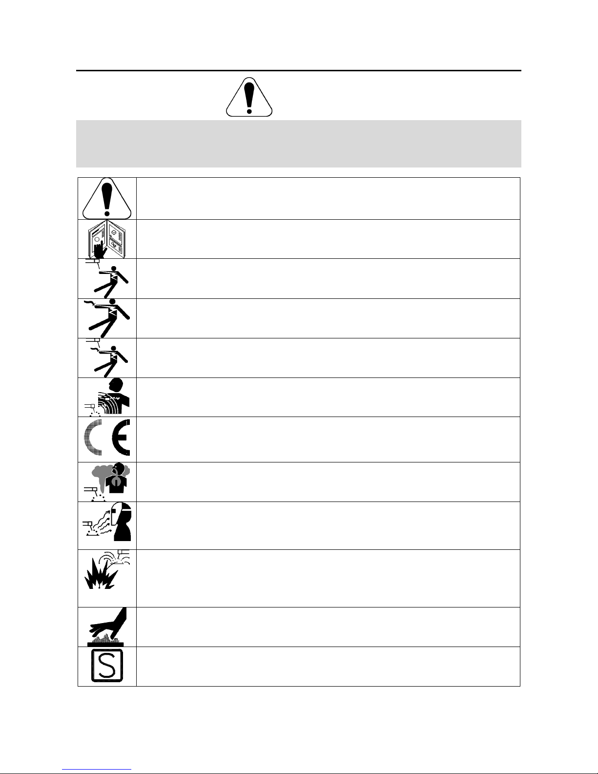
WARNING: This symbol indicates that instructions must be followed to avoid serious personal injury,
loss of life, or damage to this equipment. Protect yourself and others from possible serious injury or
death.
READ AND UNDERSTAND INSTRUCTIONS: Read and understand this manual before operating
this equipment. Arc welding can be hazardous. Failure to follow the instructions in this manual could
cause serious personal injury, loss of life, or damage to this equipment.
ELECTRIC SHOCK CAN KILL: Welding equipment generates high voltages. Do not touch the
electrode, work clamp, or connected work pieces when this equipment is on. Insulate yourself from
the electrode, work clamp, and connected work pieces.
ELECTRICALLY POWERED EQUIPMENT: Turn off input power using the disconnect switch at the
fuse box before working on this equipment. Ground this equipment in accordance with local electrical
regulations.
ELECTRICALLY POWERED EQUIPMENT: Regularly inspect the input, electrode, and work clamp
cables. If any insulation damage exists replace the cable immediately. Do not place the electrode
holder directly on the welding table or any other surface in contact with the work clamp to avoid the
risk of accidental arc ignition.
ELECTRIC AND MAGNETIC FIELDS MAY BE DANGEROUS: Electric current flowing through any
conductor creates electric and magnetic fields (EMF). EMF fields may interfere with some
pacemakers, and welders having a pacemaker shall consult their physician before operating this
equipment.
CE COMPLIANCE: This equipment complies with the European Community Directives.
FUMES AND GASES CAN BE DANGEROUS: Welding may produce fumes and gases hazardous to
health. Avoid breathing these fumes and gases. To avoid these dangers the operator must use
enough ventilation or exhaust to keep fumes and gases away from the breathing zone.
ARC RAYS CAN BURN: Use a shield with the proper filter and cover plates to protect your eyes from
sparks and the rays of the arc when welding or observing. Use suitable clothing made from durable
flame-resistant material to protect you skin and that of your helpers. Protect other nearby personnel
with suitable, non-flammable screening and warn them not to watch the arc nor expose themselves to
the arc.
WELDING SPARKS CAN CAUSE FIRE OR EXPLOSION: Remove fire hazards from the welding
area and have a fire extinguisher readily available. Welding sparks and hot materials from the welding
process can easily go through small cracks and openings to adjacent areas. Do not weld on any
tanks, drums, containers, or material until the proper steps have been taken to insure that no
flammable or toxic vapors will be present. Never operate this equipment when flammable gases,
vapors or liquid combustibles are present.
WELDED MATERIALS CAN BURN: Welding generates a large amount of heat. Hot surfaces and
materials in work area can cause serious burns. Use gloves and pliers when touching or moving
materials in the work area.
SAFETY MARK: This equipment is suitable for supplying power for welding operations carried out in
an environment with increased hazard of electric shock.
A
-2
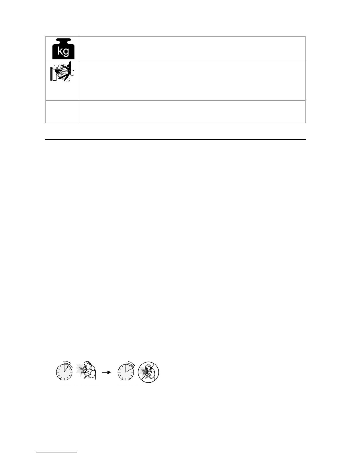
EQUIPMENT WEIGHT OVER 30kg: Move this equipment with care and with the help of another
person. Lifting may be dangerous for your physical health.
CYLINDER MAY EXPLODE IF DAMAGED: Use only compressed gas cylinders containing the
correct shielding gas for the process used and properly operating regulators designed for the gas and
pressure used. Always keep cylinders in an upright position securely chained to a fixed support. Do
not move or transport gas cylinders with the protection cap removed. Do not allow the electrode,
electrode holder, work clamp or any other electrically live part to touch a gas cylinder. Gas cylinders
must be located away from areas where they may be subjected to physical damage or the welding
process including sparks and heat sources.
HF
CAUTION: The high frequency used for contact-free ignition with TIG (GTAW) welding, can interfere
with the operation of insufficiently shielded computer equipment, EDP centers and industrial robots,
even causing complete system breakdown. TIG (GTAW) welding may interfere with electronic
telephone networks and with radio and TV reception.
Installation and Operator Instructions
Read this entire section before installation or operation
of the machine.
Location and Environment
This machine will operate in harsh environments.
However, it is important that simple preventative
measures are followed to assure long life and reliable
operation.
x Do not place or operate this machine on a surface
with an incline greater than 15° from horizontal.
x Do not use this machine for pipe thawing.
x This machine must be located where there is free
circulation of clean air without restrictions for air
movement to and from the air vents. Do not cover
the machine with paper, cloth or rags when
switched on.
x Dirt and dust that can be drawn into the machine
should be kept to a minimum.
x This machine has a protection rating of IP23S.
Keep it dry when possible and do not place it on wet
ground or in puddles.
x Locate the machine away from radio controlled
machinery. Normal operation may adversely affect
the operation of nearby radio controlled machinery,
which may result in injury or equipment damage.
Read the section on electromagnetic compatibility in
this manual.
x Do not operate in areas with an ambient
temperature greater than 40°C.
Duty cycle
The duty cycle of a welding machine is the percentage of
time in a 10 minute cycle at which the welder can
operate the machine at rated welding current.
Example: 35% duty cycle:
Welding for 3.5 minutes. Break for 6.5 minutes.
Refer to the Technical Specification section for more
information about the machine rated duty cycles.
Input Supply Connection
Check the input voltage, phase, and frequency supplied
to this machine before turning it on. The allowable input
voltage is indicated in the technical specification section
of this manual and on the rating plate of the machine.
Be sure that the machine is grounded.
Make sure the amount of power available from the input
connection is adequate for normal operation of the
machine. The fuse rating and cable sizes are both
indicated in the "Technical Specification" section of this
manual.
The machines:
x V205 2V: (230 / 400Vac, single phase)
x V270: (400Vac, three phase)
x V270 2V: (230 / 400Vac, three phase)
x V405: (400Vac, three phase)
are designed to operate on engine driven generators as
long as the auxiliary can supply adequate voltage,
frequency and power as indicated in the "Technical
Specification" section of this manual. The auxiliary
supply of the generator must also meet the following
conditions:
x Vac peak voltage: below 410V (for 230Vac input) or
720V (for 400Vac input).
x Vac frequency: in the range of 50 and 60 Hertz.
x RMS voltage of the AC waveform:
V270, V405: 400Vac ± 15%
V205 2V, V270 2V: 230Vac or 400Vac ± 10%
It is important to check these conditions because many
engine driven generators produce high voltage spikes.
Operation of this machine on engine driven generators
not conforming to these conditions is not recommended
and may damage the machine.

A
-3
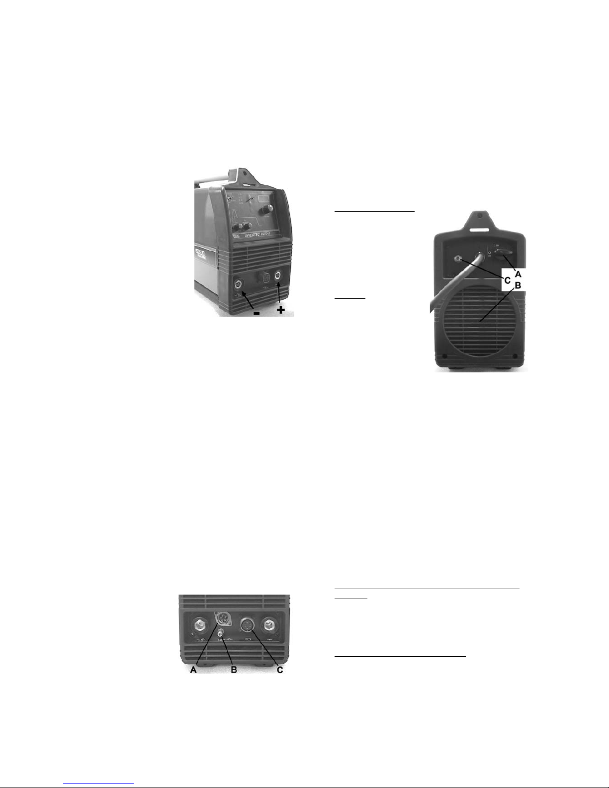
Output Connections
A quick disconnect system
using Twist-Mate cable
plugs is used for the
welding cable connections.
Refer to the following
sections for more
information on connecting
the machine for operation of
stick welding (MMA) or TIG
welding (GTAW).
Stick Welding (MMA)
First determine the proper
electrode polarity for the
electrode to be used.
Consult the electrode data
for this information. Then connect the output cables to
the output terminals of the machine for the selected
polarity. For example, if DC(+) welding will be used then
connect the electrode cable to the (+) terminal of the
machine and the work clamp to the (-) terminal. Insert
the connector with the key lining up with the keyway and
rotate approximately ¼ turn clockwise. Do not over
tighten.
For DC(-) welding switch the cable connections at the
machine so that the electrode cable is connected to (-)
and the work clamp is connected to (+).
TIG Welding (GTAW)
This machine does not include a TIG torch necessary for
TIG welding, but one may be purchased separately.
Refer to the accessories section for more information.
Most TIG welding is done with DC(-) polarity; connect
the torch cable to the (-) terminal of the machine and the
work clamp to the (+) terminal. Insert the connector with
the key lining up with the keyway and rotate
approximately ¼ turn clockwise. Do not over tighten.
For V205-S / V270-S / V405-S machine, connect the gas
hose from the TIG torch to a gas regulator on the
cylinder of gas to be used.
For V205-T / V270-T /
V405-T machine,
connect the gas hose
from the TIG torch to the
gas connector (B) on the
front of the machine. If
necessary, an extra gas
connector for the fitting
on the front of the
machine is included in the package. Next, connect the
fitting on the back of the machine to a gas regulator on
the cylinder of gas to be used. An input gas line and the
required fittings are also included in the package.
Connect the TIG torch trigger to the trigger connector (A)
on the front of the machine.
Remote Control Connection
Refer to the accessories section for a list of remote
controls. If a remote control is used, it will be connected
to the remote connector (C) on the front of the machine.
The machine will automatically detect the remote control,
turn on the REMOTE LED, and switch to remote control
mode. More information on this mode of operation will
be given in the next section.
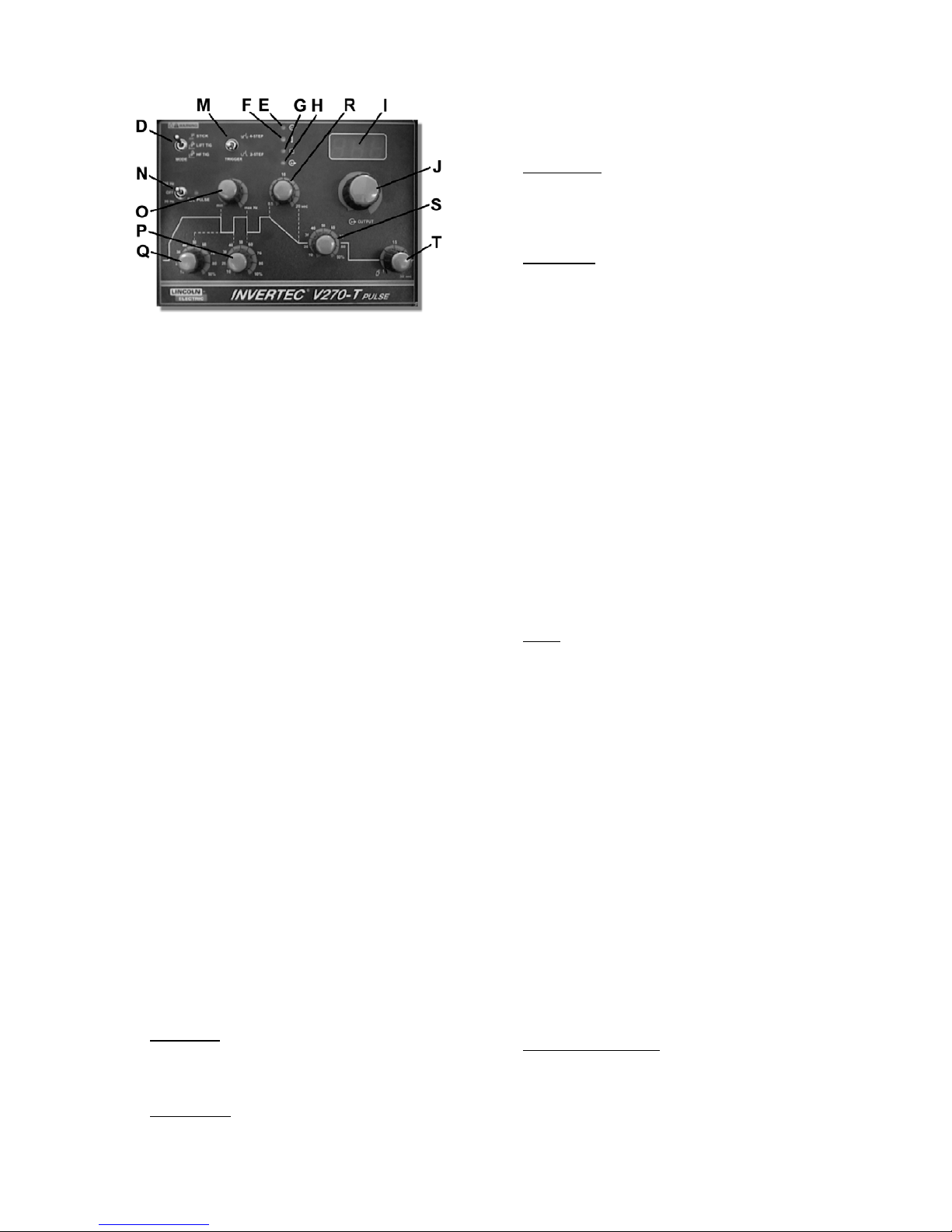
Controls and Operational Features
A. Power Switch: Controls
the input power to the
machine. Make sure the
machine is properly
connected to the input
supply before turning the
machine on.
B. Fan: The cooling fan
will turn ON when the
machine is turned ON
and it will continue to run
whenever the output of
the machine is ON. If
the output of the
machine is OFF for
more than five minutes,
the fan will turn OFF.
This reduces the amount of dirt that is deposited
inside the machine and reduces power
consumption. Refer to the Output LED section
below for more information about conditions when
the output of the machine is ON.
If a Coolarc 20 is connected to a V205-T / V270-T, it
will be turned ON and OFF with the operation of the
fan. When Stick welding mode is used the Coolarc
20 will be OFF.
If a Coolarc 30 is connected to a V405-T, it will be
turned ON and OFF with the operation of the fan.
When Stick welding mode is used the Coolarc 30
will be OFF.
C. Gas Inlet (V205-T / V270-T / V405-T only):
Connector for the TIG shielding gas. Use the
supplied gas line and connector to connect the
machine to the gas source. The gas source must
have a pressure regulator and flow gage installed.
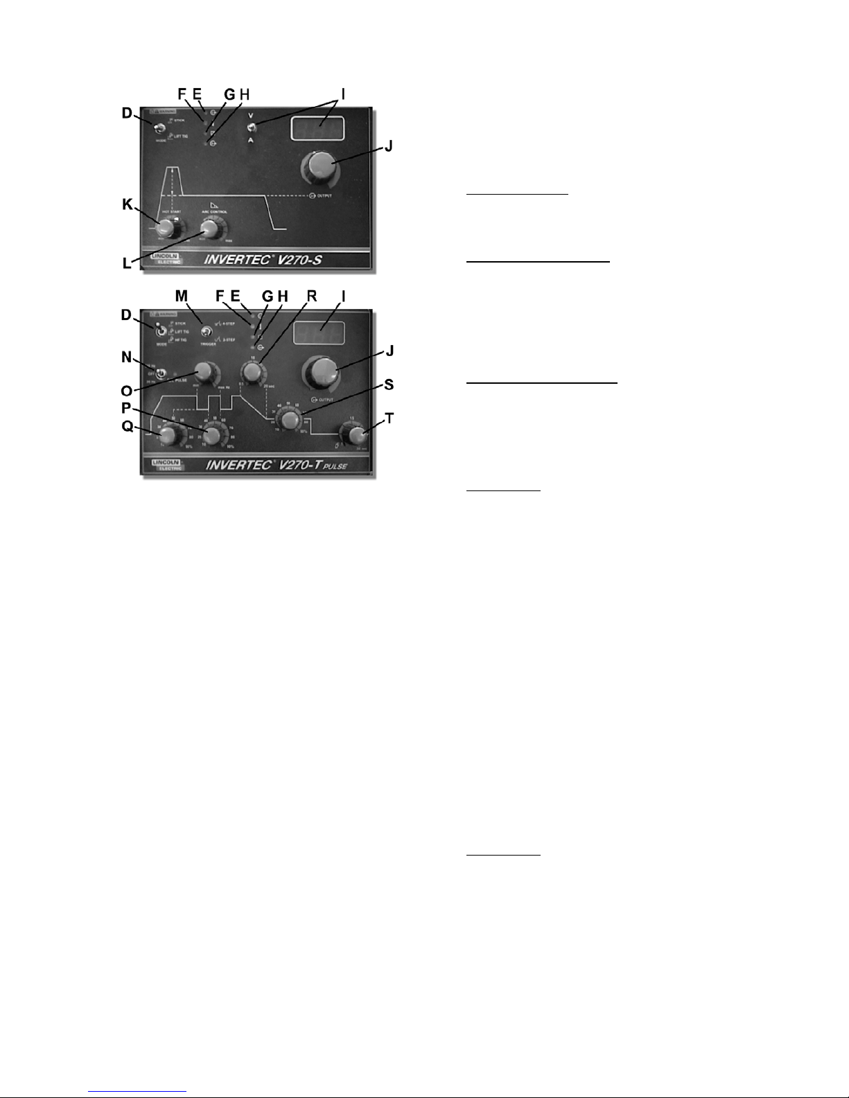
D. Mode Switch: This switch changes the welding
modes of the machine. The V205-S / V270-S /
V405-S have two welding modes: Stick (SMAW)
and Lift TIG (GTAW). The V205-T / V270-T / V405T machines have three welding modes: Stick
(SMAW), Lift TIG (GTAW) and HF TIG (GTAW).
A
-4
When the mode switch is in the Stick position, the
following welding features are enabled:
x Hot Start: This is a temporary increase in the
output current during the start of the stick
welding process. This helps ignite the arc
quickly and reliably. The amount of hot start
can be adjusted on the V205-S / V270-S /
V405-S, refer to Hot Start, described below.
x Arc Force: This is a temporary increase in the
output current during normal stick welding.
This temporary increase in output current is
used to clear intermittent connections between
the electrode and the weld puddle that occur
during normal stick welding. The amount of arc
force can be adjusted on the V205-S / V270-S /
V405-S, refer to Arc Force, described below.
x Anti-Sticking: This is a function which
decreases the output current of the machine to
a low level when the operator makes an error
and sticks the electrode to the work piece. This
decrease in current allows the operator to
remove the electrode from the electrode holder
without creating large sparks which can
damage the electrode holder.
When the mode switch is in the Lift TIG position, the
stick welding functions are disabled and the
machine is ready for Lift TIG welding. Lift TIG is a
method of starting a TIG weld by first pressing the
TIG torch electrode on the work piece in order to
create a low current short circuit. Then, the
electrode is lifted from the work piece to start the
TIG arc.
The last mode switch position, HF TIG, is only
available on the V205-T / V270-T / V405-T. When
the mode switch is in this position, the stick welding
functions are disabled and the machine is ready for
HF TIG welding. During the HF TIG mode, the TIG
arc is started by HF without pressing the electrode
on the work piece. The HF used for starting the TIG
arc will remain on for 6.5 seconds; if the arc is not
started in this time limit, the trigger sequence must
be restarted.
E. Power LED: This indicator will flash on and off
when the machine is first turned on. After
approximately 2 seconds it will stop flashing and
remain on to signal that the machine is ready.
F. Thermal LED: This indicator will turn on when the
machine is overheated and the output has been
disabled. This normally occurs when the duty cycle
of the machine has been exceeded. Leave the
machine on to allow the internal components to
cool. When the indicator turns off, normal operation
is again possible.
G. Remote LED: This indicator will turn on when a
remote control is connected to the machine via the
remote control connector. Using a remote control
will change the function of the output current control,
refer to the output current control section.
H. Output LED: This indicator turns on when the
output of the machine is on. Both the type of
machine and the position of the mode switch
determine when the output of the machine is turned
on.
V205-S / V270-S / V405-S: In the stick welding
mode, the output of the machine is automatically
turned ON. However, in the Lift TIG welding mode,
the connection of a remote control determines if the
output is ON or OFF. If a remote control is not
connected (the Remote LED is OFF) then the output
of the machine is automatically turned ON. If a
remote control is connected (the Remote LED is
ON) then the output of the machine is turned ON
and OFF by the remote connector on the front of the
machine.
V205-T / V270-T / V405-T: In stick welding mode,
the output of the machine is automatically turned
ON. However, in both of the TIG welding modes,
the output of the machine is turned ON and OFF by
the TIG torch connected to the trigger connector on
the front of the machine.
I. Meter: This meter displays the preset welding
current before welding and the actual welding
current during welding. Like the output current
control, the function of the meter is changed if a
remote control is connected. If the Remote LED is
ON, this indicates that a remote control is connected
and the meter will display the following information
before welding (during welding, the meter always
displays the actual welding current):
Stick Welding Mode: The meter displays the
preset welding current but this is adjusted from the
remote control as explained in the Output Current
Control section.
TIG Welding Modes: The meter displays the
maximum output current which is set by the output
current control knob. The preset welding current is
then adjusted by the remote control, but it is not
displayed on the meter.
V205-S / V270-S / V405-S: The machine have a
Voltage / Current switch to change the displayed
value on the meter. If this switch is set to voltage,
the meter will always display the output voltage of
the machine.
J. Output Current Control: This controls the output, or
welding, current of the machine.
The function of this control knob is changed if a
remote control is connected. If the Remote LED is
ON, this indicates that a remote control is connected
and the function of the output current control will be:
A
-5
Stick Welding Mode: The remote control will
adjust the output current of the machine:
x V205: from 5 to 200A
x V270: from 5 to 270A
x V405: from 5 to 400A
The output current control knob on the display panel
is not used.
TIG Welding Modes: The maximum output current
of the machine is set by the output current control
knob. Then the remote control adjusts the output
current from the minimum output (5A) to the value
set by the output current control knob. For example,
if the output current control knob on the machine is
set to 100A then the remote control will adjust the
output current from a minimum of 5A to a maximum
of 100A.
K. Hot Start (V205-S / V270-S / V405-S only): In stick
welding mode, this controls the amount of current
used during the start of the arc to help ignite the arc
quickly and reliably. In TIG welding mode, this is
not used.
L. Arc Force (V205-S / V270-S / V405-S only): In stick
welding mode, this controls the amount of current
used during any intermittent short circuiting of the
electrode during welding. In TIG welding mode, this
is not used.
M. Trigger Mode Switch (V205-T / V270-T / V405-T
only): This switch changes between 2-step and 4step trigger sequences. For an explanation of these
trigger sequences refer to the trigger sequences
explained below.
N. Pulsing Mode Switch (V205-T / V270-T / V405-T
only): In the TIG welding modes, this switch turns
the pulsing function ON and controls the pulsing
frequency range (20Hz or 300Hz). In Stick welding
mode, this is not used.
The Pulsing LED next to the Pulsing Mode Switch
shows the pulsing frequency when pulsing is turned
ON. With this indication, the operator can adjust the
frequency to the desired value before welding.
(Note: At higher frequencies the LED flashes very
fast and seems to be continuously ON however it is
pulsing.)
O. Pulsing Frequency Control (V205-T / V270-T /
V405-T only): When the pulsing function is ON, this
control knob will adjust the pulsing frequency. The
pulsing frequency adjustment range is 0.2-20Hz or
3-300Hz depending on the Pulsing Mode Switch
position.
P. Pulsing On-time Control (V205-T / V270-T / V405-T
only): When the pulsing function is ON, this control
knob will adjust the pulsing on-time. The on-time
can be adjusted from 10% to 90% of the pulsing
period.
Q. Pulsing Background Current Control (V205-T /
V270-T / V405-T only): When the pulsing function is
ON, this control knob will adjust the pulsing
background current. This is the current during the
low portion of the pulse waveform; it can be
adjusted from 10% to 90% of the welding current.
R. Downslope Control (V205-T / V270-T / V405-T
only): In the TIG welding modes, this control knob
will adjust the downslope time from 0.5 to 20
seconds. (The upslope time is always 0.5 seconds.)
Refer to the trigger sequence section below to
understand how downslope is activated. In Stick
welding mode, this is not used.
S. Start/Crater Current Control (V205-T / V270-T /
V405-T only): This control knob will adjust the
Start/Crater current from 10% to 90% of the welding
current. For an explanation of the start/crater
operation, refer to the trigger sequences explained
below.
T. Postflow Control (V205-T / V270-T / V405-T only):
In the TIG welding modes, this control knob will
adjust the shielding gas postflow time from 0.5 to 30
seconds. (The preflow time is always 0.5 seconds.)
In Stick welding mode, this is not used.
TIG Trigger Sequences
TIG welding can be done in either the 2-step or 4-step
mode. The specific sequences of operation for these
two trigger modes are explained below.
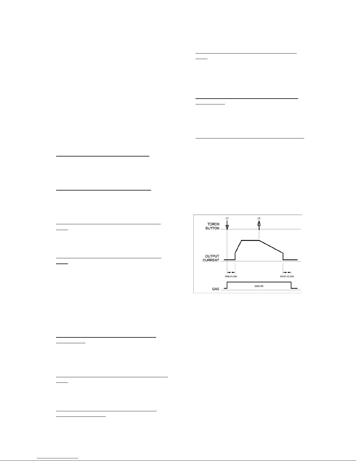
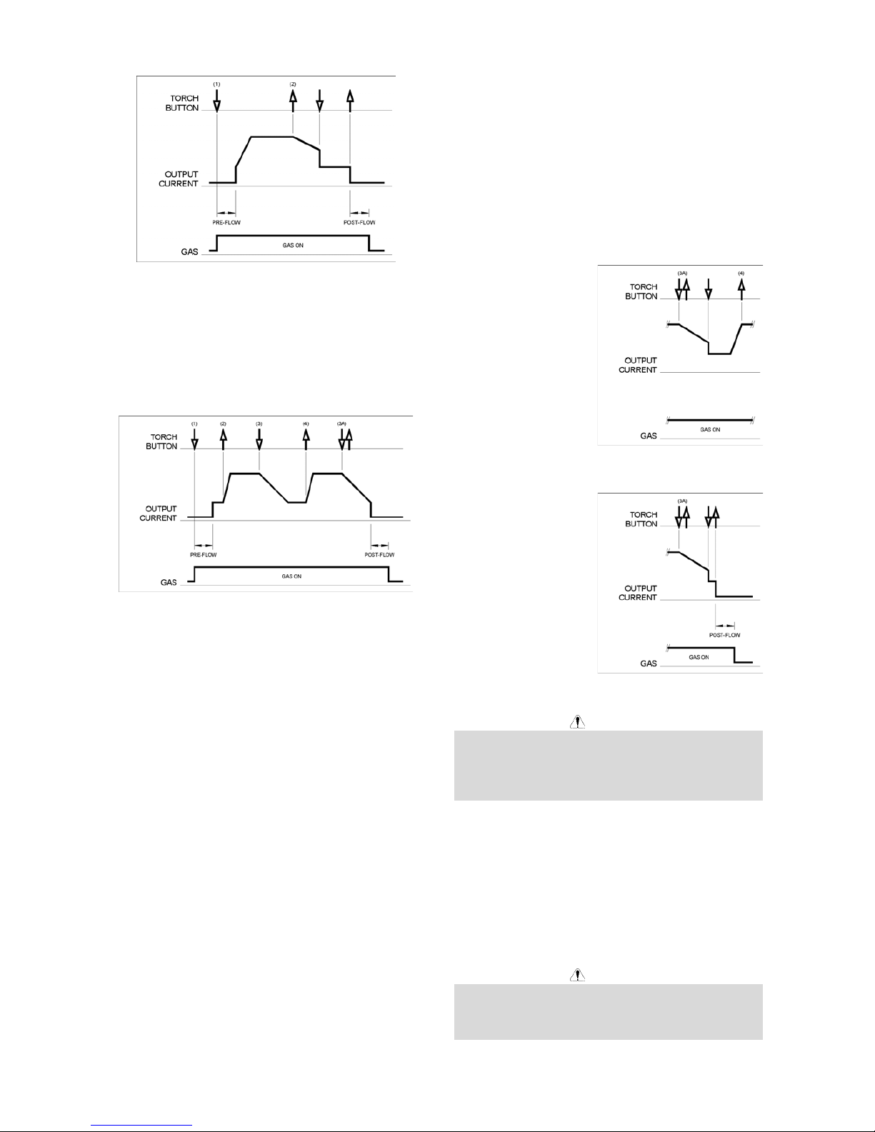
2-Step TIG Sequence
With the 2-step trigger mode and a TIG welding mode
selected, the following welding sequence will occur.
1. Press and hold the TIG torch trigger to start the
sequence. The machine will open the gas valve to
start the flow of the shielding gas. After the preflow
time, to purge air from the torch hose, the output of
the machine is turned ON. At this time the arc is
started according to the selected welding mode.
After the arc is started the output current will be
increased at a controlled rate, or upslope time, until
the Welding current is reached.
2. Release the TIG torch trigger to stop welding. The
machine will now decrease the output current at a
controlled rate, or downslope time, until the Crater
current is reached and the output of the machine is
turned OFF.
After the arc is turned OFF, the gas valve will
remain open to continue the flow of the shielding
gas to the hot electrode and work piece.
A
-6
As shown above, it is possible to press and hold the TIG
torch trigger a second time during downslope to end the
downslope function and maintain the output current at
the Crater current. When the TIG torch trigger is
released the output will turn OFF and the postflow time
will start. This operation, 2-step restart disabled, is the
default setting from the factory.
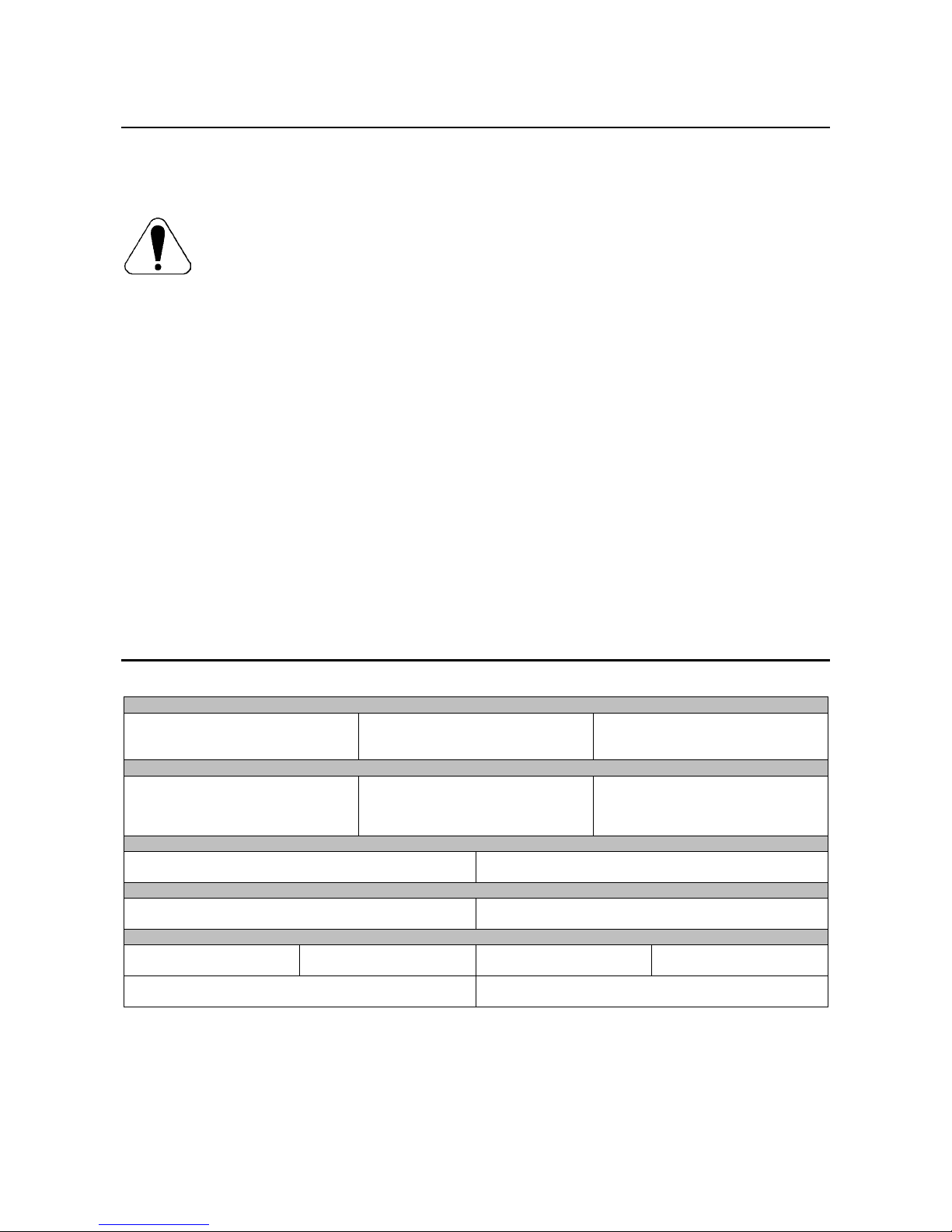
4-Step Sequence
With the 4-step trigger mode and a TIG welding mode
selected, the following welding sequence will occur.
1. Press and hold the TIG torch trigger to start the
sequence. The machine will open the gas valve to
start the flow of the shielding gas. After the preflow
time, to purge air from the torch hose, the output of
the machine is turned ON. At this time the arc is
started according to the selected welding mode.
After the arc is started the output current will be at
the Start current. This condition can be maintained
as long or as short as necessary.
If the Start current is not necessary, do not hold the
TIG torch trigger as described at the beginning of
this step. In this condition, the machine will pass
from Step 1 to Step 2 when the arc is started.
2. Releasing the TIG torch trigger starts the upslope
function. The output current will be increased at a
controlled rate, or upslope time, until the Welding
current is reached.
3. Press and hold the TIG torch trigger when the main
part of the weld is complete. The machine will now
decrease the output current at a controlled rate, or
downslope time, until the Crater current is reached.
This Crater current can be maintained as long or as
short as necessary.
This sequence has an automatic restart so welding
will continue after this step. This operation, 4-step
restart enabled, is the default setting from the
factory. If the weld is completely finished, use the
following sequence instead of step 3 described
above.
3A. Quickly press and release the TIG torch
trigger. The machine will now decrease the
output current at a controlled rate, or downslope
time, until the Crater current is reached and the
output of the machine is turned OFF. After the
arc is turned OFF the postflow time will start.
4. Release the TIG torch trigger. The output current
will again increase to the Welding current, like in
step 2, to continue welding. When the main part of
the weld is complete go to step 3.
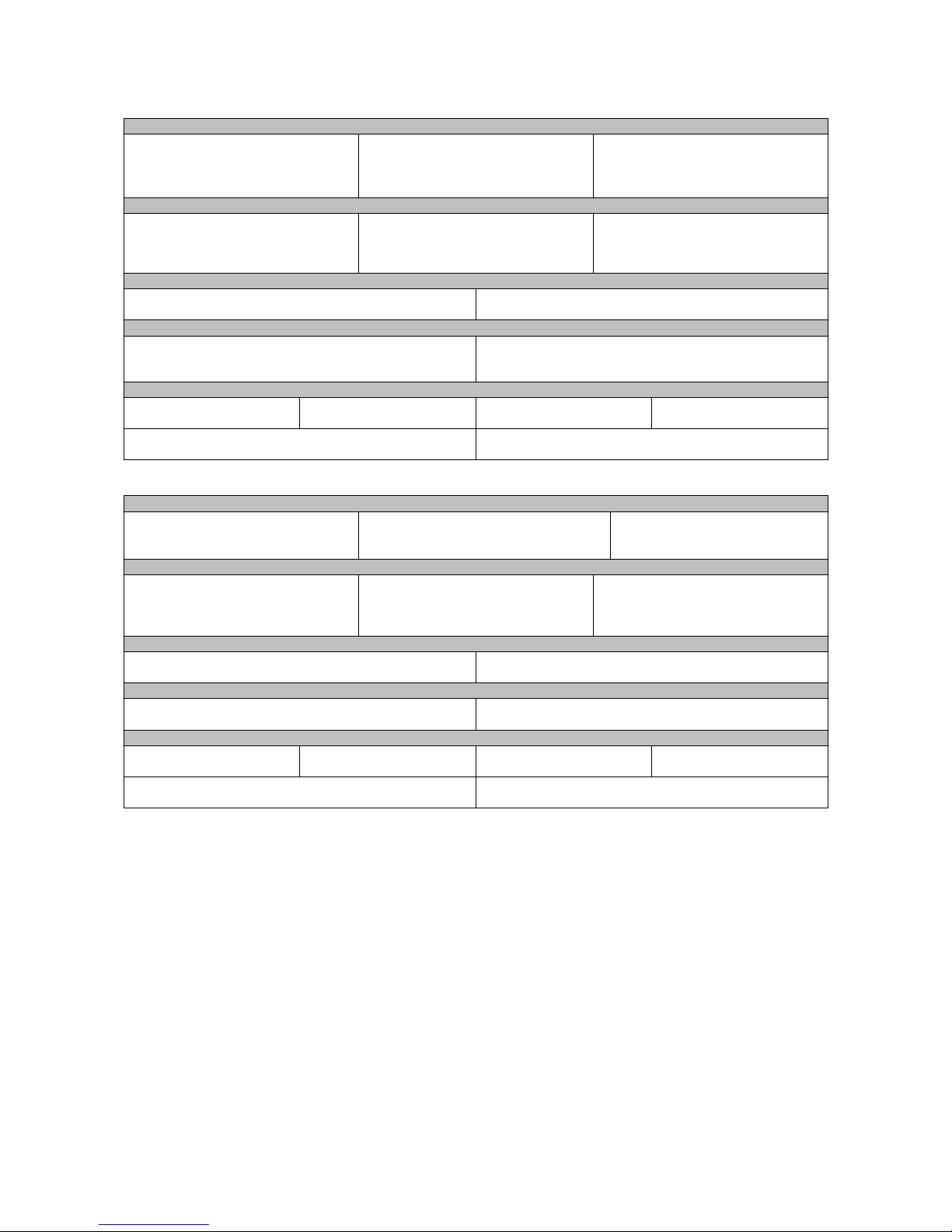
As shown here, after the
TIG torch trigger is
quickly pressed and
released from step 3A, it
is possible to press and
hold the TIG torch
trigger another time to
end the downslope time
and maintain the output
current at the Crater
current. When the TIG
torch trigger is released
the output will again
increase to the Welding
current, like in step 4, to continue welding. When the
main part of the weld is complete go to step 3.
As shown here, again
after the TIG torch
trigger is quickly pressed
and released from step
3A, it is possible to
quickly press and
release the TIG torch
trigger a second time to
end the downslope time
and stop welding.
04/03
Maintenance
WARNING
For any maintenance or repair operations it is
recommended to contact the nearest technical service
center or Lincoln Electric. Maintenance or repairs
performed by unauthorized service centers or personnel
will null and void the manufacturers warranty.
The frequency of the maintenance operations may vary
in accordance with the working environment. Any
noticeable damage should be reported immediately.
x Check cables and connections integrity. Replace, if
necessary.
x Keep clean the machine. Use a soft dry cloth to
clean the external case, especially the airflow inlet /
outlet louvers.
WARNING
Do not open this machine and do not introduce anything
into its openings. Power supply must be disconnected
from the machine before each maintenance and service.
After each repair, perform proper tests to ensure safety.
A
-7
Electromagnetic Compatibility (EMC)
11/04
This machine has been designed in accordance with all relevant directives and standards. However, it may still generate
electromagnetic disturbances that can affect other systems like telecommunications (telephone, radio, and television) or
other safety systems. These disturbances can cause safety problems in the affected systems. Read and understand
this section to eliminate or reduce the amount of electromagnetic disturbance generated by this machine.
This machine has been designed to operate in an industrial area. To operate in a domestic area it is
necessary to observe particular precautions to eliminate possible electromagnetic disturbances. The
operator must install and operate this equipment as described in this manual. If any electromagnetic
disturbances are detected the operator must put in place corrective actions to eliminate these disturbances
with, if necessary, assistance from Lincoln Electric.
Before installing the machine, the operator must check the work area for any devices that may malfunction because of
electromagnetic disturbances. Consider the following.
x Input and output cables, control cables, and telephone cables that are in or adjacent to the work area and the
machine.
x Radio and/or television transmitters and receivers. Computers or computer controlled equipment.
x Safety and control equipment for industrial processes. Equipment for calibration and measurement.
x Personal medical devices like pacemakers and hearing aids.
x Check the electromagnetic immunity for equipment operating in or near the work area. The operator must be sure
that all equipment in the area is compatible. This may require additional protection measures.
x The dimensions of the work area to consider will depend on the construction of the area and other activities that are
taking place.
Consider the following guidelines to reduce electromagnetic emissions from the machine.
x Connect the machine to the input supply according to this manual. If disturbances occur if may be necessary to take
additional precautions such as filtering the input supply.
x The output cables should be kept as short as possible and should be positioned together. If possible connect the
work piece to ground in order to reduce the electromagnetic emissions. The operator must check that connecting
the work piece to ground does not cause problems or unsafe operating conditions for personnel and equipment.
x Shielding of cables in the work area can reduce electromagnetic emissions. This may be necessary for special
applications.
Technical Specifications
V205 2V:
INPUT
Input Voltage
230 / 400V r 10%
Single Phase
Input Power at Rated Output
5.5kW @ 100% Duty Cycle
6.5kW @ 35% Duty Cycle
Frequency
50/60 Hz
RATED OUTPUT AT 40°C
Duty Cycle
(Based on a 10 min. period)
100%
35%
Output Current
170A
200A
Output Voltage
26.8 Vdc
28.0 Vdc
OUTPUT RANGE
Welding Current Range
5 - 200 A
Maximum Open Circuit Voltage
48 Vdc
RECOMMENDED INPUT CABLE AND FUSE SIZES
Fuse or Circuit Breaker Size
32A Superlag (230 / 400V input)
Input Power Cable
3 Conductor, 4mm
2
PHYSICAL DIMENSIONS
Height
385 mm
Width
215 mm
Length
480 mm
Weight
14.1 - 15.1 Kg
Operating Temperature
–10°C to +40°C
Storage Temperature
-25°C to +55°C
A
-8
V270 & V270 2V:
INPUT
Input Voltage
400V r 15% (V270)
230 / 400V r 10% (V270 2V)
Three Phase
Input Power at Rated Output
6.5kW @ 100% Duty Cycle
9.9kW @ 35% Duty Cycle
Frequency
50/60 Hz
RATED OUTPUT AT 40°C
Duty Cycle
(Based on a 10 min. period)
100%
35%
Output Current
200A
270A
Output Voltage
28.0 Vdc
30.8 Vdc
OUTPUT RANGE
Welding Current Range
5 - 270 A
Maximum Open Circuit Voltage
48 Vdc
RECOMMENDED INPUT CABLE AND FUSE SIZES
Fuse or Circuit Breaker Size
20A Superlag (400V input)
35A Superlag (230V input)
Input Power Cable
4 Conductor, 2.5mm
2
(V270)
4 Conductor, 4mm
2
(V270 2V)
PHYSICAL DIMENSIONS
Height
385 mm
Width
215 mm
Length
480 mm
Weight
13.5 - 14.5 Kg
Operating Temperature
–10°C to +40°C
Storage Temperature
-25°C to +55°C
V405:
INPUT
Input Voltage
400V r 15%
Three Phase
Input Power at Rated Output
11.3 kW @ 100% Duty Cycle
17.2 kW @ 35% Duty Cycle
Frequency
50/60 Hz
RATED OUTPUT AT 40°C
Duty Cycle
(Based on a 10 min. period)
100%
35%
Output Current
300A
400A
Output Voltage
32.0 Vdc
36.0 Vdc
OUTPUT RANGE
Welding Current Range
5 - 400 A
Maximum Open Circuit Voltage
48 Vdc
RECOMMENDED INPUT CABLE AND FUSE SIZES
Fuse or Circuit Breaker Size
30A Superlag
Input Power Cable
4 Conductor, 4mm
2
PHYSICAL DIMENSIONS
Height
500 mm
Width
275 mm
Length
610 mm
Weight
31 - 33 kg
Operating Temperature
-10°C to +40°C
Storage Temperature
-25°C to +55°C
B-1
Sicurezza
11/04
AVVERTENZA
Questa macchina deve essere impiegata solo da personale qualificato. Assicuratevi che tutte le procedure di
installazione, impiego, manutenzione e riparazione vengano eseguite solamente da persone qualificate. Leggere e
comprendere questo manuale prima di mettere in funzione la macchina. La mancata osservanza delle istruzioni di
questo manuale può provocare seri infortuni, anche mortali, alle persone, o danni alla macchina. Leggere e
comprendere le spiegazioni seguenti sui simboli di avvertenza. La Lincoln Electric non si assume alcuna responsabilità
per danni conseguenti a installazione non corretta, incuria o impiego in modo anormale.
AVVERTENZA: Questo simbolo indica che occorre seguire le istruzioni per evitare seri infortuni,
anche mortali, alle persone o danni a questa macchina. Proteggete voi stessi e gli altri dalla
possibilità di seri infortuni anche mortali.
LEGGERE E COMPRENDERE LE ISTRUZIONI: Leggere e comprendere questo manuale prima di
far funzionare la macchina. La saldatura ad arco può presentare dei rischi. La mancata osservanza
delle istruzioni di questo manuale può provocare seri infortuni, anche mortali, alle persone o danni alla
macchina.
LA FOLGORAZIONE ELETTRICA E’ MORTALE: Le macchine per saldatura generano tensioni
elevate. Non toccate l’elettrodo, il morsetto di massa o pezzi da saldare collegati alla macchina
quando la macchina è accesa. Mantenetevi isolati elettricamente da elettrodo, morsetto e pezzi
collegati a questo.
MACCHINA CON ALIMENTAZIONE ELETTRICA: Togliere l’alimentazione con l’interruttore ai fusibili
prima di svolgere operazioni su questa macchina. Mettere la macchina a terra secondo le normative
vigenti.
MACCHINA CON ALIMENTAZIONE ELETTRICA: Ispezionare periodicamente i cavi di
alimentazione, all’elettrodo e al pezzo. Se si riscontrano danni all’isolamento sostituire
immediatamente il cavo. Non posare la pinza portaelettrodo direttamente sul banco di saldatura o
qualsiasi altra superficie in contatto con il morsetto di massa per evitare un innesco involontario
dell’arco.
I CAMPI ELETTRICI E MAGNETICI POSSONO ESSERE PERICOLOSI: Il passaggio di corrente
elettrica in un conduttore produce campi elettromagnetici. Questi campi possono interferire con alcuni
cardiostimolatori (“pacemaker”) e i saldatori con un cardiostimolatore devono consultare il loro medico
su possibili rischi prima di impiegare questa macchina.
CONFORMITÀ CE: Questa macchina è conforme alle Direttive Europee.
FUMI E GAS POSSONO ESSERE PERICOLOSI: La saldatura può produrre fumi e gas dannosi alla
salute. Evitate di respirare questi fumi e gas. Per evitare il pericolo l’operatore deve disporre di una
ventilazione o di un'estrazione di fumi e gas che li allontanino dalla zona in cui respira.
I RAGGI EMESSI DALL’ARCO BRUCIANO: Usate una maschera con schermatura adatta a
proteggervi gli occhi da spruzzi e raggi emessi dall’arco mentre saldate o osservate la saldatura.
Indossare indumenti adatti in materiale resistente alla fiamma per proteggere il corpo, sia vostro che
dei vostri aiutanti. Le persone che si trovano nelle vicinanze devono essere protette da schermature
adatte, non infiammabili, e devono essere avvertite di non guardare l’arco e di non esporvisi.
GLI SPRUZZI DI SALDATURA POSSONO PROVOCARE INCENDI O ESPLOSIONI: Allontanare
dall'area di saldatura quanto può prendere fuoco e tenere a portata di mano un estintore. Gli spruzzi
o altri materiali ad alta temperatura prodotti dalla saldatura attraversano con facilità eventuali piccole
aperture raggiungendo le zone vicine. Non saldare su serbatoi, bidoni, contenitori o altri materiali fino
a che non si sia fatto tutto il necessario per assicurarsi dell'assenza di vapori infiammabili o nocivi.
Non impiegare mai questa macchina se vi è presenza di gas e/o vapori infiammabili o combustibili
liquidi.
I MATERIALI SALDATI BRUCIANO: Il processo di saldatura produce moltissimo calore. Ci si può
bruciare in modo grave con le superfici e materiali caldi della zona di saldatura. Impiegare guanti e
pinze per toccare o muovere materiali nella zona di saldatura.
B-2
MARCHIO DI SICUREZZA: Questa macchina è adatta a fornire energia per operazioni di saldatura
svolte in ambienti con alto rischio di folgorazione elettrica.
LA MACCHINA PESA OLTRE 30kg. Spostare questa macchina con cura e con l’aiuto di un’altra
persona. Il sollevamento può essere pericoloso per la vostra salute.
LE BOMBOLE POSSONO ESPLODERE SE SONO DANNEGGIATE: Impiegate solo bombole
contenenti il gas compresso adatto al processo di saldatura utilizzato e regolatori di flusso, funzionanti
regolarmente, progettati per il tipo di gas e la pressione in uso. Le bombole vanno tenute sempre in
posizione verticale e assicurate con catena ad un sostegno fisso. Non spostate le bombole senza il
loro cappello di protezione. Evitate qualsiasi contatto dell’elettrodo, della sua pinza, del morsetto di
massa o di ogni altra parte in tensione con la bombola del gas. Le bombole gas vanno collocate
lontane dalle zone dove possano restare danneggiate dal processo di saldatura con relativi spruzzi e
da fonti di calore.
HF
ATTENZIONE: L’Alta Frequenza, utilizzata per l’innesco senza contatto nella saldatura TIG (GTAW),
può interferire con l’operazione di computer non sufficientemente schermati, centri EDP e robot
industriali, provocando anche il blocco dell’intero sistema. La saldatura TIG (GTAW) può interferire
con le linee telefoniche e con la ricezione radio e TV.
Installazione e Istruzioni Operative
Leggere tutta questa sezione prima di installare e
impiegare la macchina.
Collocazione e ambiente
Questa macchina è in grado di funzionare in ambienti
difficili. E’ comunque importante seguire delle semplici
misure di prevenzione per garantirne una lunga durata e
un funzionamento affidabile.
x Non collocare o impiegare la macchina su superfici
inclinate più di 15° rispetto all’orizzontale.
x Non usare questa macchina per sgelare tubi.
x La macchina va collocata ove vi sia una circolazione
di aria pulita senza impedimenti al suo movimento in
entrata e uscita dalle feritoie. Non coprire la
macchina con fogli di carta, panni o stracci quando
è accesa.
x Tenere al minimo polvere e sporco che possano
entrare nella macchina.
x Questa macchina ha una protezione di grado
IP23S. Tenetela più asciutta possibile e non
posatela su suolo bagnato o dentro pozzanghere.
x Disponete la macchina lontana da macchinari
controllati via radio. Il suo funzionamento normale
può interferire negativamente sul funzionamento di
macchine controllate via radio poste nelle vicinanze,
con conseguenze di infortuni o danni materiali.
Leggete la sezione sulla compatibilità
elettromagnetica di questo manuale.
x Non impiegate la macchina in zone ove la
temperatura ambiente supera i 40°C.
Fattore d’intermittenza
Il fattore d’intermittenza di una macchina per saldatura è
la percentuale di tempo su un periodo di 10 minuti
durante la quale la macchina può esser fatta funzionare
alla corrente nominale.
Esempio: fattore di intermittenza del 35%
3.5 minuti di saldatura. 6.5 minuti di interruzione.
Ulteriori informazioni sui fattori di intermittenza nominali
della macchina si trovano nella sezione Specifiche
Tecniche.
Collegamento all’alimentazione
Prima di accendere la macchina controllate tensione,
fase e frequenza di alimentazione. La tensione di
alimentazione ammissibile è indicata nella sezione
“Specifiche tecniche” di questo manuale e sulla targa
della macchina. Verificate il collegamento a terra della
macchina.
Assicuratevi che l’alimentazione fornisca una potenza
sufficiente per il funzionamento normale della macchina.
Nella sezione “Specifiche tecniche” di questo manuale
sono indicati i dimensionamenti per fusibili e cavi.
Le macchine:
x V205 2V: (230 / 400Vac, monofase)
x V270: (400Vac, trifase)
x V270 2V: (230 / 400Vac, trifase)
x V405: (400Vac, trifase)
sono progettate per funzionare alimentate da gruppi
elettrogeni purché la presa ausiliaria di questi possa
fornire una tensione, frequenza e potenza adeguata
come indicato nella sezione “Specifiche tecniche” di
questo manuale. Inoltre la presa ausiliaria del gruppo
elettrogeno deve soddisfare le seguenti condizioni:
x Tensione AC di picco: inferiore a 410Vac (per
alimentazione 230Vac) o 720Vac (per alimentazione
400Vac).
x Frequenza dell’onda in AC: compresa tra 50 e 60
Hz.
B-3
x Tensione RMS dell’onda in AC:
V270, V405: 400Vac ± 15%
V205 2V, V270 2V: 230 Vac o 400 Vac ± 10%
E’ importante verificare che queste condizioni siano
rispettate perché molti gruppi elettrogeni producono
picchi di alta tensione. Non è consigliato impiegare
questa macchina con gruppi elettrogeni che non
rispettino queste condizioni perché si può danneggiare.
Collegamenti in uscita
Il collegamento dei cavi di
saldatura avviene con un
sistema rapido che impiega
connettori Twist-Mate.
Consultate le sezioni seguenti
per ulteriori informazioni sui
collegamenti da effettuare per
saldare con elettrodo (MMA)
o in TIG (GTAW).
Saldatura con elettrodo
manuale (MMA)
Per prima cosa stabilite quale
è la polarità giusta per
l’elettrodo da impiegare. Per
questo consultate i dati
dell’elettrodo. Poi collegate i cavi in uscita ai terminali di
uscita sulla macchina, secondo la polarità selezionata.
Per esempio se si salda in c.c. polo positivo (+),
collegare al terminale (+) sulla macchina il cavo
dell’elettrodo e al terminale (-) il cavo massa. Inserite il
connettore allineando la chiavetta con la scanalatura e
stringete ruotando di circa ¼ di giro in senso orario. Non
stringete troppo.
Per saldare in c.c. polo negativo invertire i collegamenti
sulla macchina in modo da avere il cavo dell’elettrodo
collegato a (-) e il cavo massa al (+).
Saldatura TIG
La macchina non comprende la torcia TIG necessaria
per saldare in TIG, che può essere acquistata a parte.
Consultate la sezione “Accessori” per ulteriori
informazioni. Per lo più le saldature TIG vengono fatte
in c.c. (-) polo negativo; collegare al terminale (-) della
macchina il cavo alla torcia e al terminale (+) il cavo al
pezzo. Inserite il connettore allineando la chiavetta con
la scanalatura e stringete ruotando di circa ¼ di giro in
senso orario. Non stringete troppo.
Per il modello V205-S / V270-S / V405-S, collegate il
tubo gas proveniente dalla torcia TIG al regolatore di
flusso sulla bombola gas in uso.
Per il modello V205-T /
V270-T / V405-T,
collegate il tubo gas
proveniente dalla torcia
TIG all’attacco gas (B)
sul davanti della
macchina. Nella
fornitura è compreso un
ulteriore attacco gas
adatto al collegamento sul davanti della macchina, se
necessario. Collegare poi l’attacco sul retro della
macchina al regolatore di flusso sulla bombola gas da
usare. Nell’imballo sono pure compresi un tubo per il
gas in arrivo con i relativi attacchi. Collegare il pulsante
della torcia TIG al connettore pulsante (A) sul davanti
della macchina.
Collegamento del comando a distanza
Far riferimento all’elenco delle parti accessorie per i
comandi a distanza. Se si impiega un comando a
distanza, va collegato al connettore apposito (C) sul
davanti della macchina. La macchina rileva
automaticamente la presenza del sistema di comando a
distanza, accende il LED comando a distanza, e si
commuta sul modo di comando a distanza. La sezione
seguente fornisce maggiori informazioni su questo modo
operativo.
Comandi e possibilità operative
A. Interruttore Generale:
Comanda l’accensione
della macchina.
Verificate che la
macchina sia collegata
correttamente alla sua
alimentazione prima di
accenderla.
B. Ventola: La ventola si
aziona quando la
macchina viene accesa
e continua a funzionare
per tutto il tempo in cui
la macchina dà potenza
in uscita. Se l’uscita
della macchina resta
inattiva per più di cinque
minuti la ventola si ferma. Si riducono così sia lo
sporco che si accumula dentro la macchina sia il
consumo di energia. Far riferimento alla sezione
LED di uscita, descritta in seguito, per maggiori
informazioni sulle situazioni in cui l’uscita della
macchina è attiva.
Unità di raffreddamento Coolarc 20 collegata a una
macchina V205-T / V270-T: l'accensione /
spegnimento dell'unità Coolarc 20 segue il
funzionamento della ventola della saldatrice. Se è
selezionata la saldatura con elettrodo manuale
(MMA) l'unità Coolarc 20 rimane spenta.
Unità di raffreddamento Coolarc 30 collegata a una
macchina V405-T: l'accensione / spegnimento
dell'unità Coolarc 30 segue il funzionamento della
ventola della saldatrice. Se è selezionata la
saldatura con elettrodo manuale (MMA) l'unità
Coolarc 30 rimane spenta.
C. Entrata gas (solo per il modello V205-T / V270-T /
V405-T): Collegamento per il gas di protezione per
TIG. Collegare la macchina alla fonte di gas
usando il tubo gas e gli attacchi forniti. Sulla fonte
di gas devono essere installati un regolatore di
pressione e un misuratore di flusso.
D. Commutatore di modo di saldatura: Comanda il
modo di saldatura della macchina. I modelli V205-S
/ V270-S / V405-S dispongono di due modi: con
elettrodo in manuale (SMAW) e Lift TIG (GTAW). I
modelli V205-T / V270-T / V405-T di tre modi:
Elettrodo (SMAW), Lift TIG (GTAW) e TIG Alta
frequenza HF TIG (GTAW).
B-4
In posizione elettrodo manuale (MMA) vengono
attivate le funzioni seguenti:
x Hot start: E’ un aumento temporaneo della
corrente in uscita all’innesco saldatura con
elettrodo (MMA) che aiuta a ottenere un
innesco d’arco rapido e affidabile. L'intensità di
Hot Start può essere regolata sui modelli V205S / V270-S / V405-S, far riferimento a Hot Start,
descritto in seguito.
x Forza d’Arco: E’ una funzione attivata durante
la saldatura con elettrodo (MMA) che permette
un aumento temporaneo della corrente in uscita
per superare i cortocircuiti da contatto
intermittente fra l’elettrodo e il bagno di
saldatura che avvengono nella normale
saldatura con elettrodo. Il valore della forza
d’arco può venire regolato sui modelli V205-S /
V270-S / V405-S, come descritto in seguito
sotto Controllo d’arco.
x Antincollamento: E’ una funzione che riduce a
un valore molto basso la corrente in uscita se
l’operatore sbaglia e incolla l’elettrodo al pezzo.
La corrente, così ridotta, permette di togliere
l’elettrodo dalla pinza senza causare forti
scariche che possono danneggiare la pinza.
Quando il commutatore di modo è nella posizione
“Lift TIG” vengono disattivate le funzioni proprie
della saldatura con elettrodo e la macchina è pronta
a saldare in Lift TIG. Il Lift TIG è un metodo di
innesco di saldatura TIG. Prima si appoggia la
torcia TIG sul pezzo e si provoca un cortocircuito a
bassa intensità di corrente, poi si solleva la torcia
per innescare un arco TIG e si può cominciare a
saldare.
L’ultima posizione del commutatore di modo, HF
TIG, è disponibile solo sui modelli V205-S / V270-S
/ V405-S. Con il commutatore in questa posizione,
l’arco TIG viene acceso dall’alta frequenza (HF)
senza dover toccare il pezzo con il tungsteno. L’alta
frequenza che accende l’arco resta in funzione per
6,5 secondi; se l’arco non si è acceso entro questo
limite di tempo, occorre ricominciare la sequenza
col pulsante.
E. LED di Accensione: Lampeggia a intermittenza non
appena si avvia la macchina. Dopo circa 2 secondi
smette di lampeggiare e resta costantemente
acceso per indicare che la macchina è in funzione.
F. LED di Protezione Termica: Si accende quando la
macchina è surriscaldata e l’uscita è stata interrotta.
Questo avviene normalmente se il fattore di
intermittenza della macchina è stato superato.
Lasciare accesa la macchina per far raffreddare i
componenti interni, quando il LED si spegne si
possono riprendere le normali operazioni di
saldatura.
G. LED di Comando a Distanza: Questa spia si
accende quando viene applicato alla macchina un
comando a distanza inserendolo nell’apposito
connettore. L’impiego di un comando a distanza
modifica la funzione del Controllo corrente in uscita,
far riferimento alla sezione sul Controllo corrente in
uscita descritta in seguito.
H. LED di Uscita: Questa spia si accende quando
l’uscita della macchina è in tensione. Questa
attivazione dell’uscita dipende sia dal tipo di
macchina sia dalla posizione del commutatore di
modo.
V205-S / V270-S / V405-S: Con saldatura elettrodo
manuale selezionata, l’uscita della macchina è
automaticamente attivata. Tuttavia, se è
selezionata la saldatura Lift TIG, l'utilizzo del
comando a distanza determina se l'uscita è in
tensione o spenta. Se il comando a distanza non è
collegato (il LED Comando a distanza è spento)
l'uscita della macchina è attivata automaticamente.
Se il comando a distanza è collegato (il LED
Comando a distanza è acceso) l'uscita della
macchina viene attivata / spenta tramite il
connettore comando a distanza posto sul frontale
della macchina.
V205-T / V270-T / V405-T: L’uscita delle macchine
viene attivata automaticamente nel modo di
saldatura con elettrodo. In entrambi i modi di
saldatura TIG l’uscita viene attivata e disattivata dal
pulsante sulla torcia TIG collegato al connettore
pulsante sul davanti della macchina.
I. Amperometro: Lo strumento indica, prima di iniziare
a saldare, la corrente di saldatura impostata, e,
durante la saldatura, la corrente in uscita effettiva.
Come per il controllo della corrente in uscita, anche
la funzione di questo strumento si modifica se si
applica un comando a distanza. L’accensione del
LED Comando a distanza indica la presenza di un
comando a distanza e l’amperometro darà, prima di
iniziare la saldatura, le seguenti indicazioni (durante
la saldatura viene comunque sempre indicata la
corrente di saldatura effettiva):

B-5
Modo Saldatura con Elettrodo: Viene indicata la
corrente impostata, che è però regolata dal
comando a distanza come visto nella precedente
Sezione Controllo corrente in uscita.
Modi di Saldatura TIG: Viene indicato il valore
massimo della corrente in uscita fissato dalla
manopola controllo uscita. La corrente di saldatura
impostata viene poi regolata dal comando a
distanza, ma lo strumento non la indica.
V205-S / V270-S / V405-S: Questi modelli hanno
sul frontale un commutatore Tensione (V) / Corrente
(A). Se impostato su "V" lo strumento visualizza
costantemente la tensione d'uscita della macchina.
J. Controllo Corrente in Uscita: Controlla la corrente in
uscita (di saldatura) dalla macchina.
La funzione di questa manopola di comando viene
modificata nelle macchine alle quali cui sia applicato
un comando a distanza. L’accensione del LED
Comando a distanza indica che è presente un
comando a distanza, e la funzione del Controllo
corrente in uscita diviene:
Modo Saldatura con Elettrodo: Il comando a
distanza regola la corrente in uscita dalla macchina:
x V205: da 5 a 200A
x V270: da 5 a 270A
x V405: da 5 a 400A
La manopola di comando sul quadro di controllo
non viene usata.
Modi di Saldatura TIG: La manopola di comando
del controllo corrente in uscita posta sul quadro
serve a fissare il valore massimo per la corrente. La
regolazione dal valore minimo (5 A) a quello
massimo fissato con la manopola avviene tramite il
comando a distanza. Ad es. ponendo su 100 A la
manopola del controllo corrente in uscita sul quadro,
il comando a distanza regolerà la corrente in uscita
fra un minimo di 5 A e un massimo di 100 A.
K. Hot Start (solo per i modelli V205-S / V270-S /
V405-S): Nel modo saldatura con elettrodo (MMA)
questo comando consente di variare il valore della
corrente erogata alla partenza della saldatura per
aiutare l'arco ad accendersi rapidamente e
affidabilmente. In modo saldatura TIG non viene
usato.
L. Controllo d’Arco (solo per i modelli V205-S / V270-S
/ V405-S): Nel modo saldatura con elettrodo,
questo comando regola il valore della corrente che
viene erogata quando l'elettrodo è per breve tempo
in cortocircuito durante la saldatura. In modo
saldatura TIG non viene usato.
M. Commutatore del Modo Pulsante (solo per i modelli
V205-T / V270-T / V405-T): Commuta fra sequenza
a 2 tempi e sequenza a 4 tempi. Vedere di seguito
la spiegazione di queste sequenze pulsante.
N. Commutatore di Modo Pulsato (solo per i modelli
V205-T / V270-T / V405-T): Nei modi di saldatura
TIG il commutatore inserisce (ON) la funzione pulse
e stabilisce la gamma di frequenza di pulsazione
(20 Hz o 300 Hz). Nel modo elettrodo non si usa.
Il LED di pulsazione (a destra del Commutatore di
Modo Pulsato) indica la frequenza di pulsazione
quando viene inserita la funzione pulse. L’operatore
può così regolare la frequenza sul valore desiderato
prima di iniziare a saldare. (Nota: Alle frequenza
più alte il LED lampeggia velocissimo e sembra
sempre acceso, anche se è realmente pulsante).
O. Controllo della Frequenza di Pulsazione (solo per i
modelli V205-T / V270-T / V405-T): Con la funzione
pulsante inserita, questa manopola regola la
frequenza di pulsazione fra 0,2 e 20 Hz o fra 3 e
300 Hz a seconda della posizione del Commutatore
di Modo Pulse.
P. Controllo del Tempo di ON nelle Pulsazioni (solo
per i modelli V205-T / V270-T / V405-T): Con la
funzione pulsante inserita, questa manopola regola
il tempo attivo in un ciclo nel pulsato. Si può
regolare il Tempo di ON fra il 10% e il 90% della
frequenza del pulsato.
Q. Controllo della Corrente di Base nelle Pulsazioni
(solo per i modelli V205-T / V270-T / V405-T): Con
la funzione pulsante inserita, questa manopola
regola il valore di base della corrente pulsante. Il
valore di base è quello raggiunto dalla corrente nella
parte bassa dell’onda di corrente pulsante; lo si può
regolare fra il 10% e il 90% della corrente di
saldatura.
R. Controllo Tempo di Discesa (solo per i modelli
V205-T / V270-T / V405-T): Nei modi di saldatura
TIG questo comando permette di regolare il tempo
di discesa fra 0,5 e 20 secondi (il tempo di salita è
sempre 0,5 secondi). Far riferimento alla sezione
delle sequenze pulsante più avanti per vedere come
viene attivato il tempo di discesa. Nel modo di
saldatura con elettrodo non si usa questa funzione.
S. Controllo della Corrente di Avvio / Riempimento
Cratere (solo per i modelli V205-T / V270-T / V405T): Questo comando permette di regolare la
Corrente di Avvio / Riempimento Cratere fra il 10%
e il 90% della corrente di saldatura. Far riferimento
alla sezione delle sequenze pulsante più avanti per
vedere come agisce questo controllo.
T. Controllo del Postgas (solo per i modelli V205-T /
V270-T / V405-T): Nei modi di saldatura TIG questa
manopola regola il tempo di postgas da 0,5 a 30
secondi (il tempo di pregas è sempre 0,5 secondi).
Nel modo di saldatura con elettrodo non si usa
questa funzione.
Sequenze pulsante in TIG
Si può saldare sia nel modo pulsante a 2 tempi sia nel
modo a 4 tempi. Di seguito vengono spiegate le
sequenze di funzionamento per i due diversi modi di
lavoro.
Sequenza TIG 2 Tempi
Messo il Commutatore di Modo Pulsante nella posizione
2 tempi, e selezionato uno dei modi di saldatura TIG, si
avrà la sequenza di saldatura qui riportata.

B-6
1. Premere e tenere premuto il pulsante della torcia
TIG per iniziare la sequenza. La macchina apre la
valvola del gas per avviare il flusso del gas
protettivo. Dopo il tempo di pregas, che elimina
l’aria dal tubo torcia, si attiva l’uscita macchina. A
questo punto scocca l’arco nel modo di saldatura
selezionato. Una volta scoccato l’arco la corrente in
uscita viene aumentata con una rampa o tempo di
salita controllato fino a quando il valore della
corrente di saldatura è raggiunto.
2. Rilasciare il pulsante della torcia TIG per arrestare
la saldatura. Adesso la macchina inizia a diminuire
la corrente in uscita con una rampa controllata,
ossia per il tempo di discesa, fino al raggiungimento
del valore di corrente di Cratere ed allo
spegnimento dell’uscita macchina.
Una volta spento l’arco, la valvola del gas rimane
aperta proseguendo a inviare il gas di protezione
sull’elettrodo caldo e sul pezzo.
Come mostrato qui sopra, durante il tempo di discesa è
possibile premere di nuovo il pulsante e tenerlo premuto
per interrompere la funzione di rampa di discesa e
mantenere la corrente in uscita al valore di Cratere. Al
momento in cui si rilascia il pulsante l’uscita viene
spenta e parte il tempo di postgas. L’operazione, 2
tempi con riavvio disabilitato, è l’impostazione di default.
Sequenza TIG 4 Tempi
Con il commutatore di modo pulsante nella posizione 4
tempi, e selezionato uno dei modi di saldatura TIG, si
avrà la sequenza di saldatura qui riportata.
1. Premere e tenere premuto il pulsante della torcia
TIG per iniziare la sequenza. La macchina apre la
valvola del gas per avviare il flusso del gas
protettivo. Dopo il tempo di pregas, che elimina
l’aria dal tubo torcia, si attiva l’uscita macchina. A
questo punto scocca l’arco nel modo di saldatura
selezionato. Una volta scoccato l’arco la corrente in
uscita verrà portata al valore della corrente di Avvio.
Questa condizione può venire mantenuta per
quanto tempo si desidera, molto o poco che sia.
Se non è necessario disporre della corrente di
Avvio, il pulsante torcia non va tenuto premuto
come descritto all’inizio di questa sequenza. In
questo caso la macchina passa automaticamente
dal Tempo 1 al Tempo 2 quando l’arco si innesca.
2. Rilasciare il pulsante torcia TIG per iniziare la
funzione di salita. La corrente in uscita viene
aumentata con una rampa o tempo di salita
controllato fino a quando il valore della corrente di
saldatura è raggiunto.
3. Premere il pulsante torcia TIG e tenerlo premuto
quando l’operazione di saldatura vera e propria è
terminata. Adesso la macchina inizia a diminuire la
corrente in uscita con una rampa controllata, ossia
per il tempo di discesa, fino al raggiungimento del
valore di corrente di Cratere. La corrente di Cratere
può venire mantenuta per tutto il tempo desiderato,
lungo o corto che sia.
Questa sequenza dispone di riavvio automatico in
modo che la saldatura continuerà dopo questo
Tempo 3. L’operazione, 4 tempi con riavvio
abilitato, è l’impostazione di default. Se si è
completata del tutto l’operazione di saldatura,
invece del Tempo 3 descritto impiegare la sequenza
che segue.
3A. Premere il pulsante torcia TIG e rilasciarlo
rapidamente. Adesso la macchina inizia a
diminuire la corrente in uscita con una rampa
controllata, ossia per il tempo di discesa, fino al
raggiungimento della corrente di Cratere e
infine sarà spenta l’uscita della macchina. Una
volta spento l’arco inizia il tempo di postgas.
4. Rilasciare il pulsante torcia TIG. La corrente in
uscita aumenta di nuovo fino alla corrente di
saldatura, come nel Tempo 2, per continuare a
saldare. Quando l’operazione di saldatura vera e
propria è terminata, passare al Tempo 3.
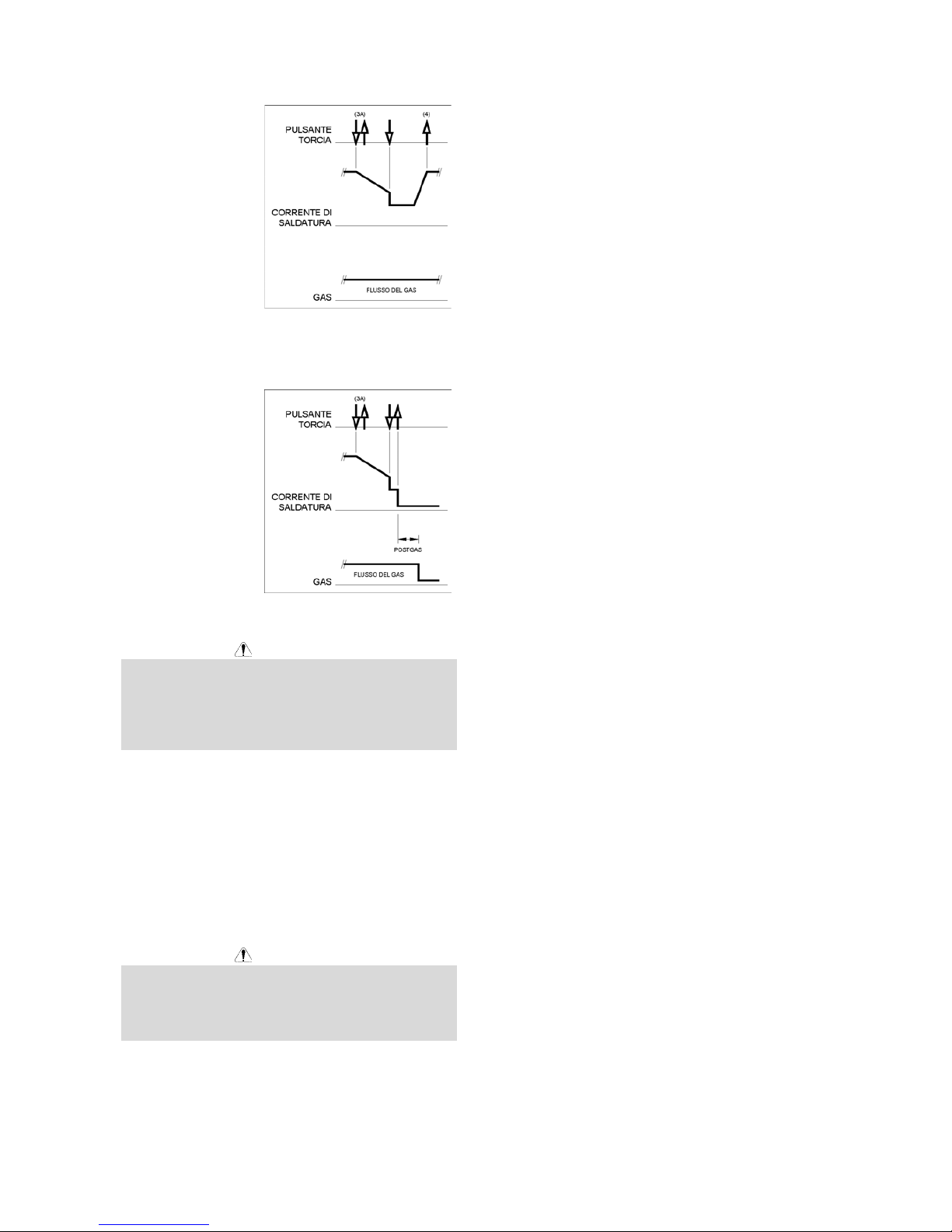
B-7
Come indicato qui,
una volta che si sia
premuto e rilasciato
rapidamente il
pulsante torcia TIG
come visto al Tempo
3A, si può di nuovo
premerlo e tenerlo
premuto per terminare
il tempo di discesa e
mantenere la corrente
in uscita al valore
della corrente di
Cratere. Rilasciando il
pulsante torcia TIG, l’uscita viene di nuovo aumentata
fino alla corrente di saldatura, come nel Tempo 4, per
continuare a saldare. Quando l’operazione di saldatura
vera e propria è terminata, passare al Tempo 3.
Come indicato qui,
quando si sia premuto
e rilasciato
rapidamente il
pulsante torcia TIG
come visto al Tempo
3A, si può, una
seconda volta,
premerlo e rilasciarlo
rapidamente per
terminare il tempo di
discesa e arrestare la
saldatura.
04/03
Manutenzione
AVVERTENZA
Per ogni operazione di manutenzione o riparazione si
raccomanda di rivolgersi al più vicino centro di
assistenza tecnica della Lincoln Electric. Manutenzioni o
riparazioni effettuate da personale o centri di servizio
non autorizzati fanno decadere la garanzia del
fabbricante.
La frequenza delle operazioni di manutenzione può
variare dipendentemente dall'ambiente di lavoro.
Evidenti danneggiamenti all'apparecchiatura devono
essere immediatamente notificati.
x Verificare l'integrità dei cavi e delle loro connessioni.
Sostituire le parti, se necessario.
x Tenere pulita la macchina. Usare un panno
morbido e asciutto; pulire in particolare le feritoie
per l'entrata / uscita dell'aria.
AVVERTENZA
Non smontare questa macchina e non introdurre nulla
nelle sue aperture. Scollegare la macchina
dall'alimentazione prima di ogni operazione di
manutenzione a assistenza. Dopo ogni riparazione,
eseguire gli appropriati test di sicurezza.
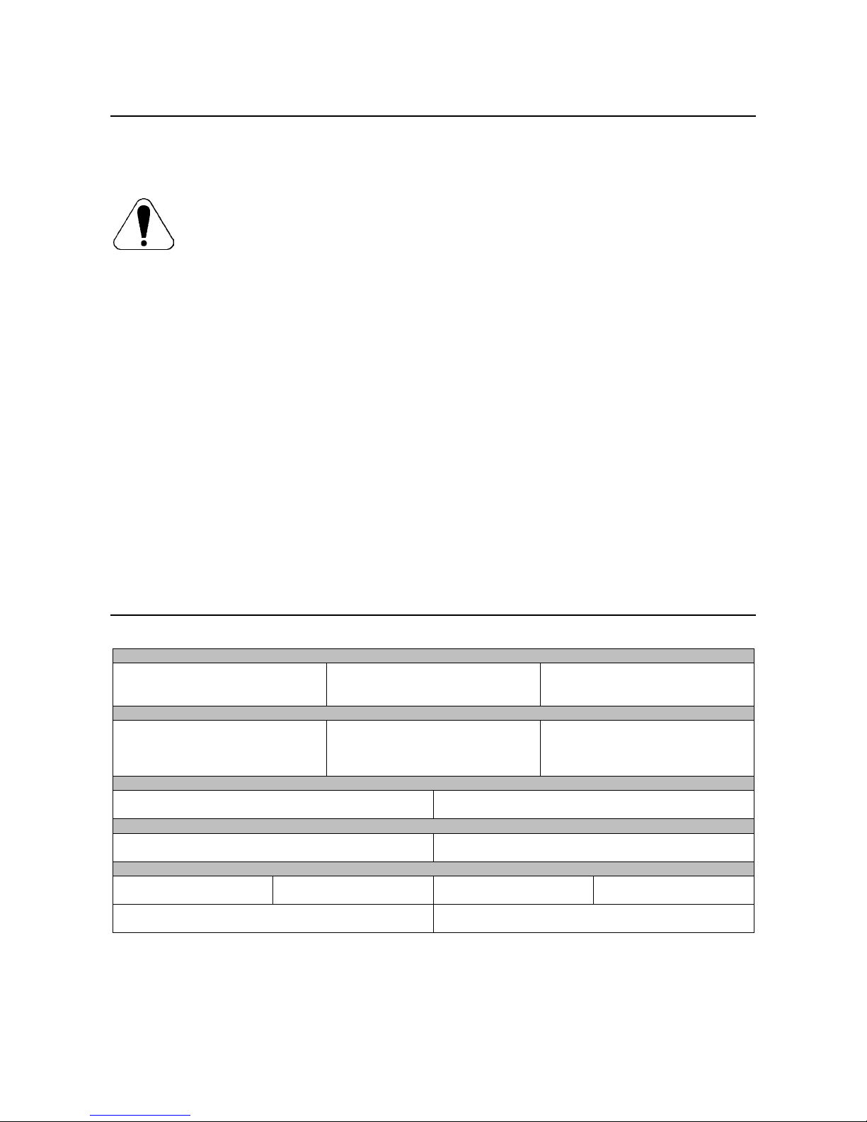
B-8
Compatibilità Elettromagnetica (EMC)
11/04
Questa macchina è stata progettata nel rispetto di tutte le direttive e normative in materia. Tuttavia può generare dei
disturbi elettromagnetici che possono interferire con altri sistemi come le telecomunicazioni (telefono, radio o televisione)
o altri sistemi di sicurezza. I disturbi possono provocare problemi nella sicurezza dei sistemi interessati. Leggete e
comprendete questa sezione per eliminare o ridurre il livello dei disturbi elettromagnetici generati da questa macchina.
La macchina è stata progettata per funzionare in ambienti di tipo industriale. Il suo impiego in ambienti
domestici richiede particolari precauzioni per l’eliminazione dei possibili disturbi elettromagnetici.
L’operatore deve installare e impiegare la macchina come precisato in questo manuale. Se si riscontrano
disturbi elettromagnetici l’operatore deve porre in atto azioni correttive per eliminarli, avvalendosi, se
necessario, dell’assistenza della Lincoln Electric.
Prima di installare la macchina, controllate se nell’area di lavoro vi sono dispositivi il cui funzionamento potrebbe risultare
difettoso a causa di disturbi elettromagnetici. Prendete in considerazione i seguenti:
x Cavi di entrata o di uscita, cavi di controllo e cavi telefonici collocati nell’area di lavoro, presso la macchina o nelle
adiacenze di questa.
x Trasmettitori e/o ricevitori radio o televisivi. Computers o attrezzature controllate da computer.
x Impianti di sicurezza e controllo per processi industriali. Attrezzature di taratura e misurazione.
x Dispositivi medici individuali come cardiostimolatori (pacemakers) o apparecchi acustici.
x Verificare che macchine e attrezzature funzionanti nell’area di lavoro o nelle vicinanze siano immuni da possibili
disturbi elettromagnetici. L’operatore deve accertare che tutte le attrezzature e dispositivi nell’area siano compatibili.
A questo scopo può essere necessario disporre misure di protezione aggiuntive.
x L’ampiezza dell’area di lavoro da prendere in considerazione dipende dalla struttura dell’area e dalle altre attività
che vi si svolgono.
Per ridurre le emissioni elettromagnetiche della macchina tenete presenti le seguenti linee guida.
x Collegare la macchina alla fonte di alimentazione come indicato da questo manuale. Se vi sono disturbi, può essere
necessario prendere altre precauzioni, come un filtro sull’alimentazione.
x I cavi in uscita vanno tenuti più corti possibile e l’uno accanto all’altro. Se possibile mettere a terra il pezzo per
ridurre le emissioni elettromagnetiche. L’operatore deve controllare che questa messa a terra non provochi
problemi o pericoli alla sicurezza del personale e della macchina e attrezzature.
x Si possono ridurre le emissioni elettromagnetiche schermando i cavi nell’area di lavoro. Per impieghi particolari
questo può diventare necessario.
Specifiche Tecniche
V205 2V:
ALIMENTAZIONE
Tensione di alimentazione
230 / 400V r 10%
Monofase
Potenza assorbita per uscita nominale
5.5kW per fattore di intermittenza 100 %
6.5kW per fattore di intermittenza 35%
Frequenza
50/60 Hz
USCITA NOMINALE a 40°C
Fattore di intermittenza
(su periodo di 10 minuti)
100%
35%
Corrente in uscita
170A
200A
Tensione nominale in uscita
26.8 Vdc
28.0 Vdc
USCITA
Gamma corrente di saldatura
5 - 200 A
Massima tensione a vuoto
48 Vdc
DIMENSIONI RACCOMANDATE PER CAVI E FUSIBILI
Fusibile o Magnetotermico
32A ritardato (alimentazione 230 / 400V)
Cavo di alimentazione
3 conduttori da 4mm
2
DATI FISICI - DIMENSIONI
Altezza
385 mm
Larghezza
215 mm
Lunghezza
480 mm
Peso
14.1 - 15.1 kg
Temperatura di impiego
-10°C a +40°C
Temperatura di immagazzinamento
-25°C a + 55°C
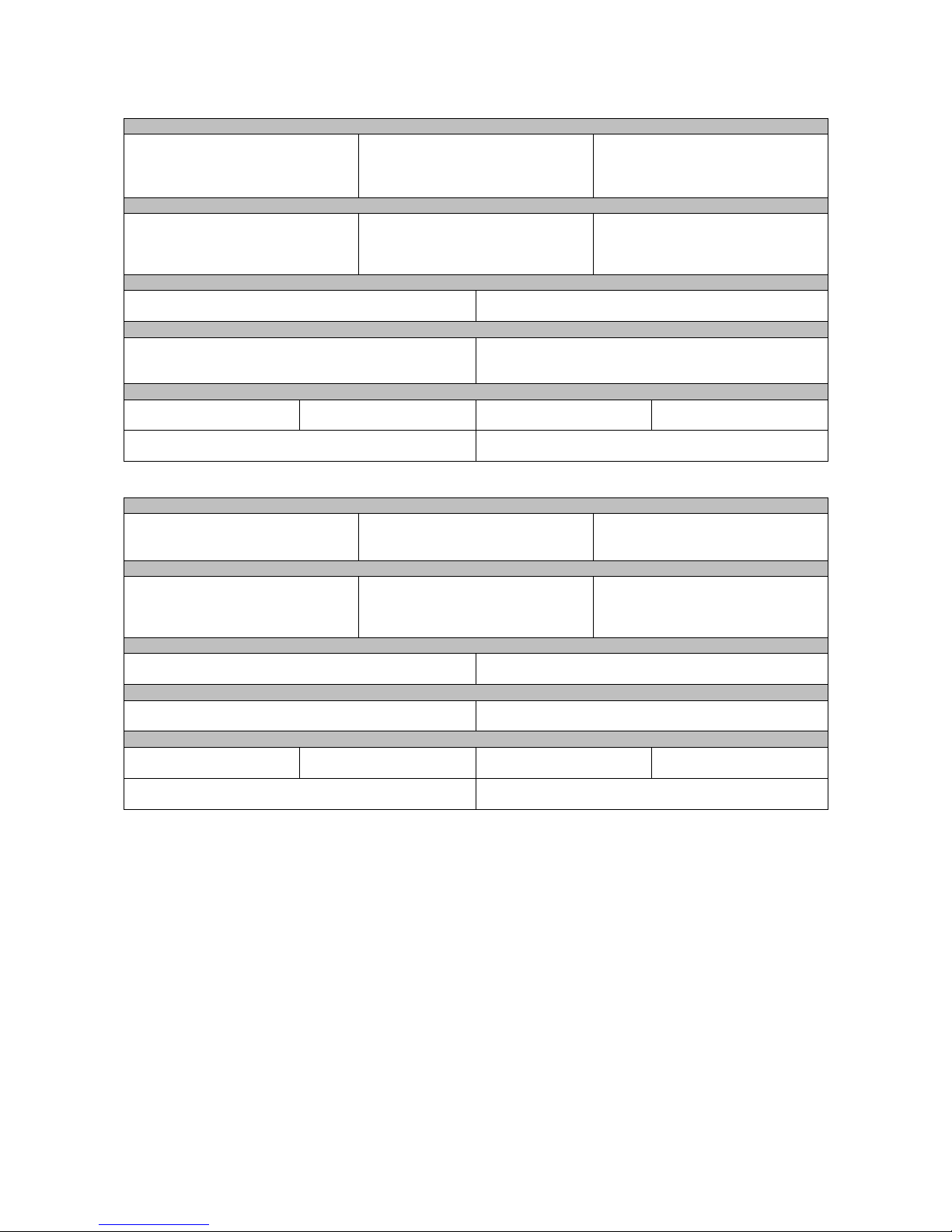
B-9
V270 e V270 2V:
ALIMENTAZIONE
Tensione di alimentazione
400V r 15% (V270)
230 / 400V r 10% (V270 2V)
Trifase
Potenza assorbita per uscita nominale
6,5 kW per fattore di intermittenza 100 %
9,9 kW per fattore di intermittenza 35%
Frequenza
50/60 Hz
USCITA NOMINALE a 40°C
Fattore di intermittenza
(su periodo di 10 minuti)
100%
35%
Corrente in uscita
200A
270A
Tensione nominale in uscita
28.0 Vdc
30.8 Vdc
USCITA
Gamma corrente di saldatura
5 - 270 A
Massima tensione a vuoto
48 Vdc
DIMENSIONI RACCOMANDATE PER CAVI E FUSIBILI
Fusibile o Magnetotermico
20A ritardato (alimentazione 400V)
35A ritardato (alimentazione 230V)
Cavo di alimentazione
4 conduttori da 2,5 mm
2
(V270)
4 conduttori da 4mm
2
(V270 2V)
DATI FISICI - DIMENSIONI
Altezza
385 mm
Larghezza
215 mm
Lunghezza
480 mm
Peso
13,5 - 14,5 kg
Temperatura di impiego
-10°C a +40°C
Temperatura di immagazzinamento
-25°C a + 55°C
V405:
ALIMENTAZIONE
Tensione di alimentazione
400V r 15%
Trifase
Potenza assorbita per uscita nominale
11,3 kW per fattore di intermittenza 100 %
17,2 kW per fattore di intermittenza 35%
Frequenza
50/60 Hz
USCITA NOMINALE a 40°C
Fattore di intermittenza
(su periodo di 10 minuti)
100%
35%
Corrente in uscita
300A
400A
Tensione nominale in uscita
32.0 Vdc
36.0 Vdc
USCITA
Gamma corrente di saldatura
5 - 400 A
Massima tensione a vuoto
48 Vdc
DIMENSIONI RACCOMANDATE PER CAVI E FUSIBILI
Fusibile o Magnetotermico
30A Ritardato
Cavo di alimentazione
4 conduttori da 4 mm
2
DATI FISICI – DIMENSIONI
Altezza
500 mm
Larghezza
275 mm
Lunghezza
610 mm
Peso
31 - 33 kg
Temperatura di impiego
-10°C a +40°C
Temperatura di immagazzinamento
-25°C a + 55°C

C-1
Sicherheitsmaßnahmen / Unfallschutz
02/05
ACHTUNG
Diese Anlage darf nur von ausgebildetem Fachpersonal genutzt, gewartet und repariert werden. Schließen Sie dieses
Gerät nicht an, arbeiten Sie nicht damit oder reparieren Sie es nicht, bevor Sie diese Betriebsanleitung gelesen und
verstanden haben. Bei Nichtbeachtung der Hinweise kann es zu gefährlichen Verletzungen bis hin zum Tod oder zu
Beschädigungen am Gerät kommen. Beachten Sie auch die folgenden Beschreibungen der Warnhinweise. Lincoln
Electric ist nicht verantwortlich für Fehler, die durch inkorrekte Installation, mangelnde Sorgfalt oder Fehlbenutzung des
Gerätes entstehen.
ACHTUNG: Dieses Symbol gibt an, dass die folgenden Hinweise beachtet werden müssen, um
gefährliche Verletzungen bis hin zum Tode oder Beschädigungen am Gerät zu verhindern. Schützen
Sie sich und andere vor gefährlichen Verletzungen oder dem Tode.
BEACHTEN SIE DIE ANLEITUNG: Lesen Sie diese Anleitung sorgfältig, bevor Sie das Gerät in
Betrieb nehmen. Bei Nichtbeachtung der Hinweise kann es zu gefährlichen Verletzungen bis hin zum
Tod oder zu Beschädigungen am Gerät kommen.
STROMSCHLÄGE KÖNNEN TÖDLICH SEIN: Schweißgeräte erzeugen hohe Stromstärken.
Berühren Sie keine stromführenden Teile oder die Elektrode mit der Haut oder nasser Kleidung.
Schützen Sie beim Schweißen Ihren Körper durch geeignete isolierende Kleidung und Handschuhe.
ELEKTRISCHE GERÄTE: Schalten Sie die Netzspannung am Sicherungskasten aus oder ziehen Sie
den Netzstecker, bevor Arbeiten an der Maschine ausgeführt werden. Erden Sie die Maschine
gemäß den geltenden elektrischen Bestimmungen.
ELEKTRISCHE GERÄTE: Achten Sie regelmäßig darauf, dass Netz-, Werkstück- und
Elektrodenkabel in einwandfreiem Zustand sind und tauschen Sie diese bei Beschädigung aus.
Legen Sie den Elektrodenhalter niemals auf den Schweißarbeitsplatz, damit es zu keinem
ungewollten Lichtbogen kommt.
ELEKTRISCHE UND MAGNETISCHE FELDER BERGEN GEFAHREN: Elektrischer Strom, der
durch ein Kabel fließt, erzeugt ein elektrisches und magnetisches Feld (EMF). EMF Felder können
Herzschrittmacher beeinflussen. Bitte fragen Sie Ihren Arzt, wenn Sie einen Herzschrittmacher
haben, bevor Sie dieses Gerät benutzen.
CE Konformität: Dieses Gerät erfüllt die CE-Normen.
RAUCH UND GASE KÖNNEN GEFÄHRLICH SEIN: Schweißen erzeugt Rauch und Gase, die
gesundheitsschädlich sein können. Vermeiden Sie das Einatmen dieser Metalldämpfe. Benutzen Sie
eine Schweißrauchabsaugung, um die Dämpfe abzusaugen.
LICHTBÖGEN KÖNNEN VERBRENNUNGEN HERVORRUFEN: Tragen Sie geeignete
Schutzkleidung und Schutzmasken für Augen, Ohren und Körper, um sich vor Spritzern und
Strahlungen zu schützen. Warnen Sie auch in der Umgebung befindliche Personen vor den Gefahren
des Lichtbogens. Lassen Sie niemanden ungeschützt den Lichtbogen beobachten.
SCHWEISSPRITZER KÖNNEN FEUER ODER EXPLOSIONEN VERURSACHEN: Entfernen Sie
feuergefährliche Gegenstände vom Schweißplatz und halten Sie einen Feuerlöscher bereit.
Schweißen Sie keine Behälter, die brennbare oder giftige Stoffe enthalten, bis diese vollständig
geleert und gesäubert sind. Schweißen Sie niemals an Orten, an denen brennbare Gase, Stoffe oder
Flüssigkeiten vorhanden sind.
GESCHWEISSTE MATERIALIEN KÖNNEN VERBRENNUNGEN VERURSACHEN: Schweißen
verursacht hohe Temperaturen. Heiße Materialien können somit ernsthafte Verbrennungen
verursachen. Benutzen Sie Handschuhe und Zangen, wenn Sie geschweißte Materialien berühren
oder bewegen.
S-ZEICHEN: Dieses Gerät darf Schweißstrom in Umgebungen mit erhöhter elektrischer Gefährdung
liefern.
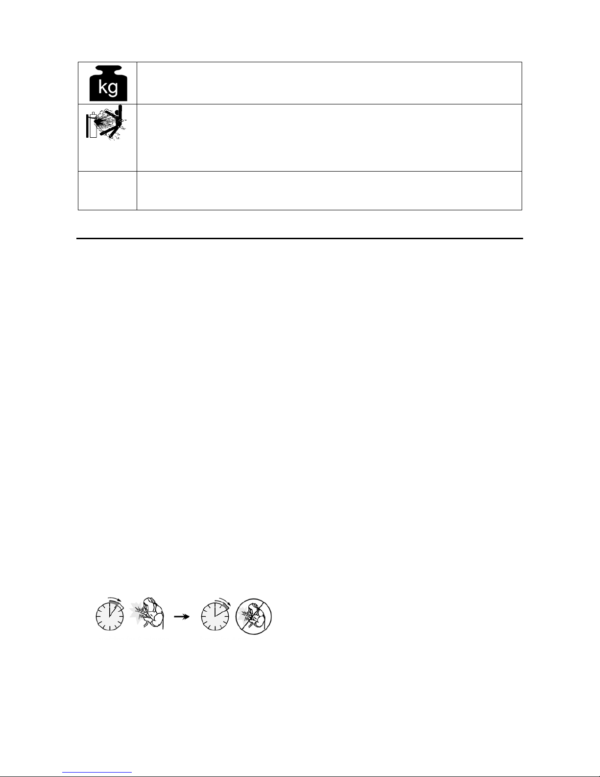
C-2
Gerätegewicht über 30kg: Bitte bewegen oder heben Sie das Gerät mit äußerster Sorgfalt und mit
Unterstützung einer weiteren Person. Das Heben des Gerätes kann Ihre körperliche Gesundheit
gefährden.
DEFEKTE GASFLASCHEN KÖNNEN EXPLODIEREN: Benutzen Sie nur Gasflaschen mit dem für
den Schweißprozess geeigneten Gas und ordnungsgemäßen Druckreglern, die für dieses Gas
ausgelegt sind. Lagern Sie Gasflaschen aufrecht und gegen Umfallen gesichert. Bewegen Sie keine
Gasflasche ohne Ihre Sicherheitskappe. Berühren Sie niemals eine Gasflasche mit der Elektrode,
Elektrodenhalter, Massekabel oder einem anderen stromführenden Teil. Gasflaschen dürfen nicht an
Plätzen aufgestellt werden, an denen sie beschädigt werden können, inklusive Schweißspritzern und
Wärmequellen.
HF
ACHTUNG: Die Hochfrequenzspannung, die zum berührungslosen Zünden beim WIG-Schweißen
eingesetzt wird, kann den Betrieb von unzureichend abgeschirmten Computern, EDV-Zentren und
Industrierobotern bis zum Totalausfall beeinflussen. WIG-Schweißen kann außerdem Telefonnetze
sowie den Radio- und Fernsehempfang stören.
Installation und Bedienungshinweise
Lesen Sie diesen Abschnitt, bevor Sie das Gerät
installieren oder benutzen.
Standort und Umgebung
Diese Maschine ist für den Einsatz in rauer Umgebung
ausgelegt. Dennoch sollten die folgenden Punkte für
eine lange Lebensdauer beachtet werden:
x Stellen Sie das Gerät nicht auf Ebenen mit mehr als
15° horizontaler Neigung.
x Die Maschine darf nicht zum Auftauen von Rohren
verwendet werden.
x Die Maschine muss an einem Ort installiert werden,
an dem eine freie und saubere Luftzirkulation
gewährleistet ist. Bedecken Sie die Maschine nicht
mit Papier, Stoff oder Plane, wenn sie eingeschaltet
ist.
x Staub, der in die Maschine gelangen kann, sollte
auf ein Minimum reduziert werden.
x Diese Maschine ist nach IP23S geschützt. Halten
Sie die Maschine trocken, und stellen Sie diese
nicht auf nassen Untergrund oder in Wasserpfützen.
x Halten Sie die Maschine von elektronischen
Anlagen fern. Normaler Betrieb kann zu Störungen
dieser Anlagen führen. Lesen Sie hierzu auch das
Kapitel "Elektromagnetische Verträglichkeit".
x Betreiben Sie die Maschine nicht bei Temperaturen
über 40°C.
Einschaltdauer
Die Einschaltdauer ist die Zeit in Prozent von 10 Min.,bei
der mit der eingestellten Stromstärke ununter-brochen
geschweißt werden kann.
Beispiel: 35% Einschaltdauer:
3.5 Minuten Schweißen. 6.5 Minuten Unterbrechung.
Für weitere Informationen bezüglich der Einschaltdauer
lesen Sie bitte die Bedienungsanleitung.
Netzeingangskabel
Überprüfen Sie Netzeingangsspannung, Phase und
Frequenz der Netzversorgung, bevor Sie die Maschine
in Betrieb nehmen. Die zugelassene Netzeingangsspannung finden Sie in dieser Bedienungsanleitung
unter Technische Daten und auf dem Typenschild der
Maschine. Prüfen Sie die Erdverbindung der Maschine
zum Netzeingang.
Vergewissern Sie sich, ob der Stromanschluss für den
normalen Betrieb der Maschine geeignet ist. Die
Bemessung der Sicherung und die Kabelgrößen sind im
Kapitel "Technische Daten" dieser Anleitung angegeben.
Das Schweißgerät:
x V205 2V: (230 / 400V Wechselstrom, einphasig)
x V270: (400V Wechselstrom, dreiphasig)
x V270 2V: (230 / 400V Wechselstrom, dreiphasig)
x V405: (400V Wechselstrom, dreiphasig)
kann an Dieselschweißaggregate angeschlossen
werden. Soweit dieses Aggregat die entsprechenden
Anschlusswerte (Spannung, Frequenz und Leistung)
gemäß der Maschinenspezifikation liefert. Das Aggregat
muß folgendes ermöglichen:
x Wechselstrom Scheitelspannung unter 410V (für
230V Wechselstrom Eingangswert) oder 720V (für
400V Wechselspannung Eingangswert
x Frequenz Wechselstrom: im Bereich 50 bis 60
Hertz.
x Nennanschlußspannung AC Kurvenform:
V270, V405: 400Vac ± 15%
V205 2V, V270 2V: 230Vac oder 400Vac ± 10%
Es ist wichtig, diese Rahmenbedingungen zu
überprüfen, da viele alte Generatoren sehr hohe
Spitzenspannungen abgeben. Generatoren die diesen
Rahmen nicht einhalten, können die Maschine
beschädigen und sind nicht erlaubt.
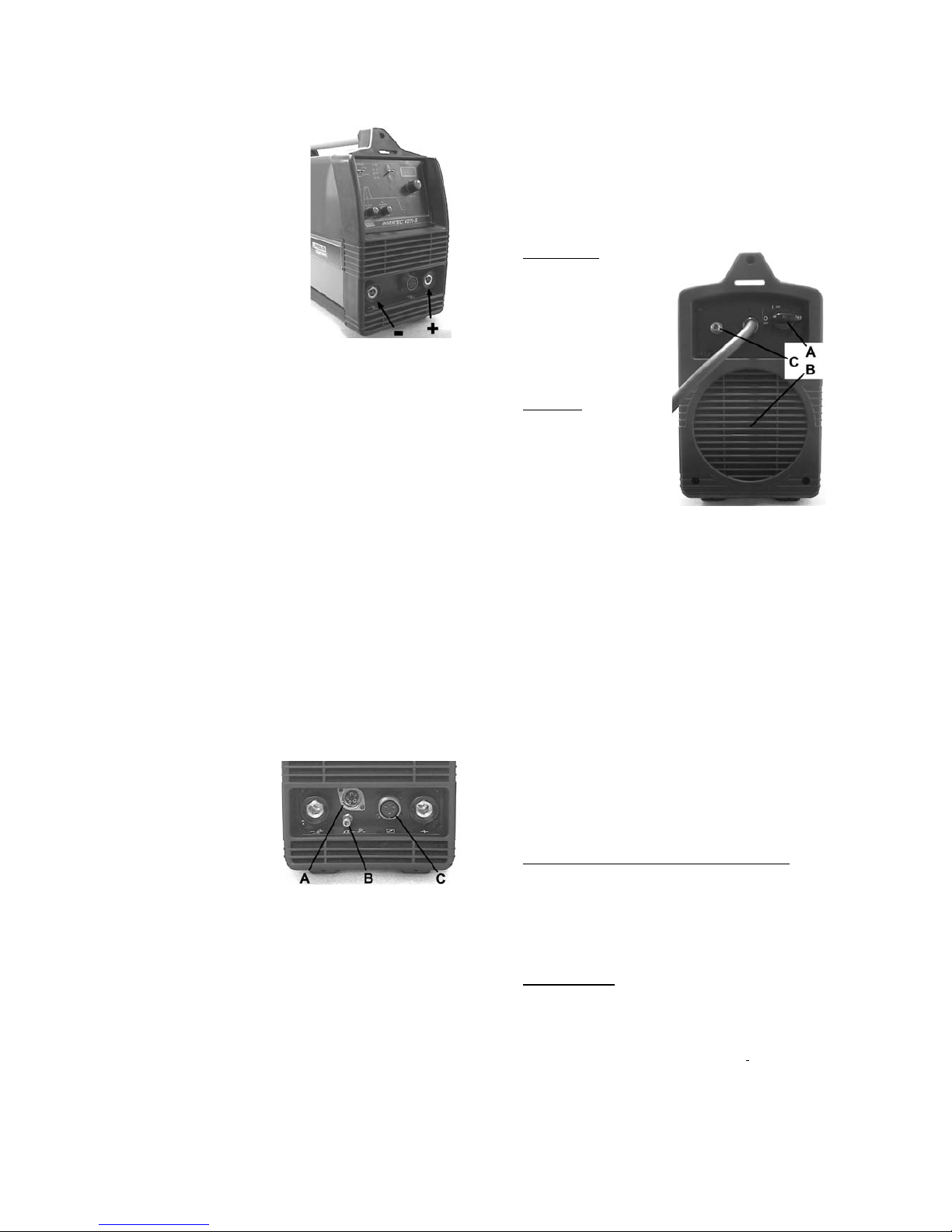
C-3
Ausgangsbuchsen
Zum Anschluss der
Schweißkabel werden TwistMate Kabelbuchsen
verwendet. Genauere
Beschreibungen zum
Anschluss eines WIG-Brenners
und der Schweißkabel zum EHandschweißen folgen in
dieser Bedienungsanleitung.
Stabelektodenschweißen
(MMA)
Sehen Sie zuerst auf der
Verpackung der zu
verschweißenden Elektrode
nach der benötigten Polarität. Dann verbinden Sie das
Schweißkabel und das Massekabel gemäß der
benötigten Polarität mit den Ausgangsbuchsen. Wenn
z.B. DC+ zum Schweißen benötigt wird, schließen Sie
das Elektrodenkabel an den (+) Anschluss der Maschine
an und das Massekabel am (-) Anschluss. Stecken Sie
den Stecker in die Gerätebuchse (Nut und Feder
deckungsgleich), und drehen Sie diesen um etwa ¼
Umdrehung in Uhrzeigerrichtung. Ziehen Sie den
Stecker aber nicht zu fest an.
Beim DC(-) Schweißen verfahren Sie anders herum, so
dass das Elektrodenkabel an (-) und das Massekabel an
(+) angeschlossen ist.
WIG Schweißen
Die Maschine wird ohne WIG Brenner ausgeliefert, der
aber separat zugekauft werden kann (siehe Zubehör).
Die meisten WIG-Schweißungen werden mit DC(-)
geschweißt. Verbinden Sie das Brennerkabel mit dem () Anschluss der Maschine und das Massekabel mit dem
(+) Anschluss. Stecken Sie den Stecker in die
Gerätebuchse (Nut und Feder Deckungsgleich), und
drehen Sie diesen um etwa ¼ Umdrehung in
Uhrzeigerrichung. Ziehen Sie diesen aber nicht zu fest
an.
Für V205-S / V270-S /
V405-S Geräte:
Verbinden Sie den
Gasschlauch vom WIGBrenner mit dem
Druckminderer des
Gaszylinders.
Für V205-T / V270-T /
V405-T Geräte: Verbinden Sie den Gasschlauch vom
Brenner mit der Gasverbindung (B) an der Vorderseite
des Gerätes. Eine zusätzliche Gasverbindung zur
Anpassung an der Vorderseite des Gerätes ist
mitgeliefert worden. Verbinden Sie jetzt die Kupplung an
der Rückseite des Gerätes mit einem Druckminderer am
Gaszylinder. Eine Gaseinführung und benötigte
Verbindungen sind ebenfalls mitgeliefert worden.
Verbinden Sie den Drücker des WIG-Brenners mit der
Drückerverbindung (A) an der Vorderseite des Gerätes.
Gasschlauch vom WIG-Brenner mit dem Druckminderer
des Gaszylinders.
Anschließen von Fernreglern
Eine entsprechende Aufstellung geeigneter Fernregler
ist dem Kapitel "Zubehör" entnehmbar. Zur Verwendung
eines Fernreglers wird dieser am Fernregleranschluss
(C) auf der Frontseite der Maschine angeschlossen. Die
Maschine wird den Fernregler automatisch erkennen,
die Fernregler-Kontrollleuchte einschalten und auf
Fernreglerbetrieb umschalten. Weitere Details zum
Fernreglerbetrieb werden im nachfolgenden Kapitel
genauer beschrieben.
Bedienungselemente und
Kontrollanzeigen
A. Netzschalter: Schaltet
die Eingangsspannung
zur Maschine.
Versichern Sie sich,
dass die Maschine
sorgfältig an das
Stromnetz
angeschlossen ist, bevor
Sie sie einschalten.
B. Ventilator: Der
Ventilator schaltet sich
mit dem Einschalten der
Maschine an und läuft
so lange, wie die
Maschine zur
Leistungsabgabe bereit
ist. Wenn an den
Ausgangsbuchsen der Maschine für mehr als 5
Minuten keine entnehmbare Schweißspannung
anliegt, schaltet der Ventilator automatisch ab. Dies
reduziert im Betrieb die innere Verunreinigung der
Maschine und spart Energie. Weitere Details über
den Zustand der Bereitschaft zur Leistungsabgabe
der Maschine lesen Sie bitte im Kapitel "Output
LED".
Falls an das Modell V205-T / V270-T ein
Wasserkühlgerät Coolarc 20 angeschlossen wurde,
wird dies parallel mit dem Ventilator ein- und
ausgeschaltet. Wenn die Anlage im
Stabelektroden-Modus betrieben wird, bleibt der
Wasserkühler automatisch abgeschaltet.
Ist am V405-T ein Wasserkühlgerät Coolarc 30
angeschlossen, wird dies parallel mit dem Ventilator
ein- und ausgeschaltet. Wenn die Anlage im
Stabelektroden-Modus betrieben wird, bleibt der
Wasserkühler automatisch abgeschaltet.
C. Gas-Eingang (nur V205-T / V270-T / V405-T):
Anschluss für das Schutzgas zum WIG-Schweißen.
Benutzen Sie den mitgelieferten Gasschlauch mit
seinen Anschlüssen, um die Maschine mit der
Gasversorgung zu verbinden. Die Gasversorgung
(z.B. Flasche) muß mit einem Druckminderer und
Durchflussregler ausgerüstet sein.
D. Modus-Schalter: Dieser Schalter ändert den
Schweiß-Modus des Gerätes. Die V205-S / V270-S
/ V405-S haben zwei Schweiß-Modi:
Stabelektroden-Modus (SMAW) und Lift TIG
(GTAW). Die V205-T / V270-T / V405-T haben drei
Schweiß-Modi: Stabelektroden-Modus (SMAW), Lift
TIG (GTAW) und HF TIG (GTAW).
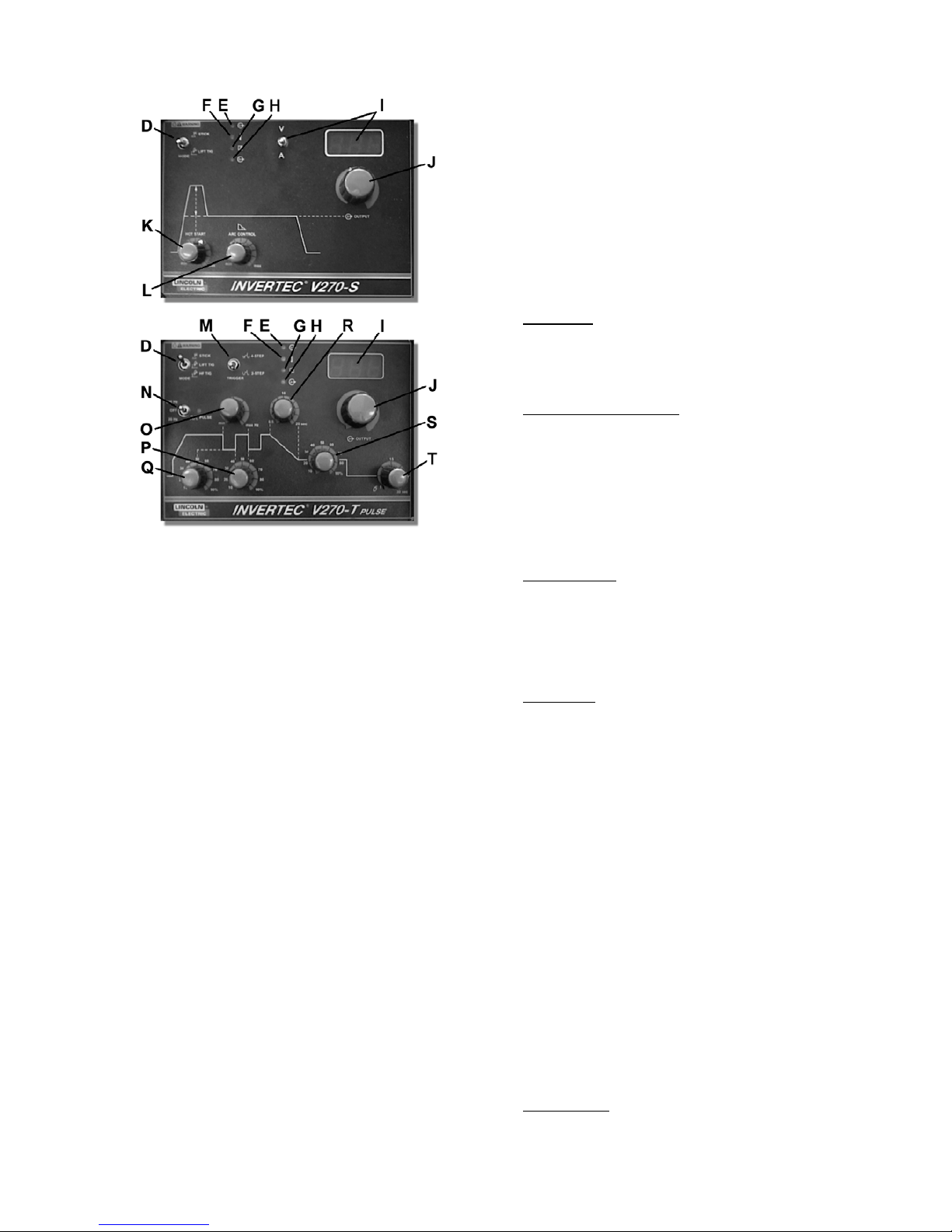
C-4
Wenn der Betriebsartumschalter auf der Position EHand (Stabelektroden) steht, sind die folgenden
Besonderheiten des Schweißprozesses aktiviert:
x Hot Start: Eine zeitlich begrenzte Steigerung
den Ausgangsstroms während des Starts des
Elektroden-Schweißens. So zündet der
Lichtbogen schnell und zuverlässig. Der Hot
Start an der V205-S / V270-S / V405-S ist
einstellbar. Wie unten beschrieben.
x Arc Force: Eine zeitlich begrenzte Steigerung
des Ausgangsstromes während des
Elektroden-Schweißens. Diese zeitlich
begrenzte Steigerung des Ausgangsstromes
benötigt man zum Ausgleich wechselnder
Verbindungen zwischen Elektrode und
Schmeldzbad. Arc Force an der V205-S /
V270-S / V405-S ist einstellbar. Wie unten
beschrieben.
x Anti-Sticking: Dies ist eine Funktion, die den
Ausgangsstrom der Maschine auf ein geringes
Niveau reduziert, wenn der Schweißer einen
Fehler macht, und die Elektrode am Werkstück
festklebt. Diese Verminderung des Stroms
ermöglicht dem Schweißer, die Elektrode aus
dem Halter zu entfernen, ohne dass dabei
durch zu starke Funkenbildung der
Elektrodenhalter beschädigt wird.
Wenn der Betriebsartschalter auf WIG-Schweißen
mit Berührungszünden (Lift-Arc) steht, sind alle
Funktionen zum Stabelektrodenschweißen
deaktiviert, und die Maschine ist bereit zum WIGSchweißen mit Berührungszündung (Lift-Arc). Beim
Lift-Arc zur Zündung des Lichtbogens wird zunächst
die Wolfram-Nadel auf das Werkstück aufgesetzt,
um einen geringen Kurzschlussstrom zu erzeugen.
Danach, wenn die Wolfram-Nadel vom Werkstück
abgehoben wird, zündet der eigentliche
Schweißlichtbogen.
Die letzte Modus-Schalter-Position, HF TiG, steht
nur bei der V205-T / V270-T / V405-T zur
Verfügung. Wenn der Modus-Schalter in die HFTIG-Position geschaltet ist, sind die ElektrodenSchweiß-Funktionen ausgeschaltet. Das Gerät ist
fertig zum HF WIG-Schweißen. In diesem Modus
startet der WIG Lichtbogen, ohne daß die Elektrode
das Werkstück berührt. Die HF, die zum Starten
des WIG-Lichtbogens benutzt wird, hält für 6,5
Sekunden an. Ist der Lichtbogen nicht innerhalb
dieser Zeit gestartet, muß der Start-Ablauf
wiederholt werden.
E. Power LED: Diese Kontrollleuchte blinkt zunächst,
wenn die Maschine eingeschaltet wird. Nach etwa
2 Sekunden wird sie nicht mehr blinken, sondern
dauerhaft leuchten, um die Betriebsbereitschaft der
Maschine anzuzeigen.
F. Überlastungsanzeige LED: Diese Kontrollleuchte
schaltet sich ein, wenn die Maschine überhitzt
wurde, und der Stromausgang dadurch automatisch
abgeschaltet wurde. Dies passiert in der Regel
dann, wenn die Einschaltdauer der Maschine
überschritten wurde. Lassen Sie in diesem Fall die
Maschine eingeschaltet, damit die inneren Bauteile
weiter gekühlt werden können. Wenn anschließend
dann diese Leuchte erlischt, kann die Maschine
wieder den normalen Betrieb aufnehmen.
G. Fernregler LED: Diese Kontrollleuchte schaltet sich
ein, wenn ein Fernregler über den
Fernregleranschluss mit der Maschine verbunden
wird. Der Anschluss eines Fernreglers verändert
die Funktion zur Einstellung der
Schweißstromstärke. (Siehe Abschnitt "Einstellung
der Schweißstromstärke")
H. Output LED: Diese Kontrollleuchte schaltet sich ein,
wenn an den Ausgangsbuchsen der Maschine
Schweißspannung anliegt. Sowohl der Typ der
Maschine, als auch die Position des
Betriebsartschalters legen fest, wann die
Ausgangsbuchsen unter Spannung stehen:
V205-S / V270-S / V405-S: Im E-Hand-Modus liegt
automatisch Schweißspannung an den
Ausgangsbuchsen an. Im WIG-Modus mit Lift-ArcZündung bestimmt der Anschluss eines Fernreglers,
ob Schweißspannung an den Ausgangsbuchsen
anliegt oder nicht. Wenn kein Fernregler
angeschlossen ist (Fernregler LED leuchtet nicht),
wird die Schweißspannung automatisch dauerhaft
eingeschaltet. Ist jedoch ein Fernregler
angeschlossen (Fernregler LED leuchtet), wird die
Schweißspannung über den Fernregleranschluss an
der Front der Maschine ein- oder ausgeschaltet.
V205-T / V270-T / V405-T: Im E-Hand-Modus liegt
automatisch Schweißspannung an den
Ausgangsbuchsen an. In beiden WIG-Betriebsarten
wird der Stromausgang über den an der Front der
Maschine angeschlossenen Brenner ein- und
ausgeschaltet.
I. Digitalanzeige: Dieses Anzeigeinstrument zeigt die
eingestellte Stromstärke vor dem Schweißen und
den tatsächlichen Strom während des Schweißens.

C-5
Wie die Einstellung des Ausgangsstroms, wird die
Funktion dieser Anzeige verändert, wenn ein
Fernregler angeschlossen wird. Wenn die
Fernregler-LED leuchtet und somit anzeigt, dass ein
Fernregler angeschlossen ist, wird das
Anzeigeinstrument die folgenden Informationen vor
dem Schweißen anzeigen: (Während des
Schweißens zeigt das Instrument immer den
tatsächlichen Schweißstrom an.)
Stabelektrodenbetrieb: Die Anzeige zeigt die
eingestellte Stromstärke, wie sie über den
Fernregler eingestellt wurde und im Abschnitt
"Regelung der Ausgangsstromstärke" näher
beschrieben wird.
WIG-Betrieb: Die Anzeige zeigt den maximalen
Ausgangsstrom an, der am Drehknopf der Maschine
eingestellt wurde. Die dann über den Fernregler
voreingestellte Ausgangsstromstärke wird nicht auf
der Anzeige sichtbar.
V205-S / V270-S / V405-S: Diese Maschinen
haben einen Spannungs-/Stromschalter, der den
angezeigten Wert auf dem Anzeiger ändert. Ist
dieser Schalter auf Spannung geschaltet, zeigt er
immer die Ausgangsspannung der Maschine an.
J. Einstellung der Schweißstromstärke: Dies regelt die
Ausgangsstromstärke der Maschine.
Die Funktion dieses Drehknopfes wird durch den
Anschluss eines Fernreglers verändert. Wenn die
Fernregler LED leuchtet, zeigt dies, dass ein
Fernregler angeschlossen ist. Die Funktionsweise
der Ausgangsstromregelung ist dann wie folgt:
Stabelektroden Modus: Der Fernregler regelt den
Ausgangsstrom der Maschine:
x V205: von 5 bis 200 A
x V270: von 5 bis 270 A
x V405: von 5 bis 400 A
Der Ausgangsstrom-Schalter an der Anzeigeplatte
wird nicht benötigt.
WIG-Schweiß-Betrieb: Der maximale
Ausgangsstrom wird durch den Drehknopf
(Schweißstromstärke) am Bedienfeld der Maschine
eingestellt. Der Fernregler regelt dann den
Ausgangsstrom vom Minimalwert (5A) bis zu dem
vorher am Gerät eingestellten Maximalwert. Wird
also beispielsweise der Ausgansstrom am
Drehknopf der Maschine auf 100A eingestellt, kann
mit dem Fernregler der Ausgangsstrom im Bereich
von 5-100A eingestellt werden.
K. Hot Start (nur V205-S / V270-S / V405-S): Im E-
Hand-Modus kann über diesen Drehknopf die
Intensität der kurzzeitigen Anhebung des
Startstroms verändert werden, durch die ein
schnelleres und zuverlässigeres Zünden der
Elektrode erreicht wird.
L. Arc Force (nur V205-S / V270-S / V405-S): Im E-
Hand-Betrieb steuert dies die Stärke des bei
drohendem Festkleben kurz ansteigenden Stroms
und somit die Intensität der Funktion Arc Force. Im
WIG-Schweiß-Betrieb ist diese Funktion deaktiviert.
M. 2-Takt-/4-Takt-Umschalter (nur V205-T / V270-T /
V405-T): Dieser Schalter wählt zwischen dem 2Takt- und 4-Takt-Betrieb des Brennertasters. Zur
weiteren Erklärung dieser Schaltfunktionen lesen
Sie bitte im Kapitel "WIG-Brennertaster
Schaltfunktionen" weiter unten.
N. Pulsfunktionsschalter (nur V205-T / V270-T / V405-
T): Im WIG-Betrieb aktiviert dieser Schalter die
Pulsfunktion und wählt den Bereich der
Pulsfrequenz (20Hz oder 300Hz). Im
Stabelektrodenbetrieb ist diese Funktion außer
Betrieb.
Die Kontrollleuchte neben dem
Pulsfunktionsschalter blinkt entsprechend der
Pulsfrequenz, wenn die Pulsfunktion aktiv ist. Mit
Hilfe dieser Anzeige kann der Schweißer die
Pulsfrequenz vor dem Schweißen auf den
gewünschten Wert einstellen. (Hinweis: Bei sehr
hohen Frequenzen blinkt die LED so schnell, dass
sie als dauerhaft leuchtend erscheint.).
O. Einstellung der Pulsfrequenz (nur V205-T / V270-T /
V405-T): Wenn die Pulsfunktion eingeschaltet ist,
lässt sich über diesen Drehknopf die Pulsfrequenz
einstellen. Die Pulsfrequenz kann je nach dem
vorab gewählten Pulsbereich zwischen 0,2-20 Hz
oder zwischen 3-300 Hz eingestellt werden.
P. Einstellung der Breite des Impulsintervalls (nur
V205-T / V270-T / V405-T): Wenn die Pulsfunktion
aktiviert ist, kann über diesen Drehknopf das
Verhältnis der Dauer jedes einzelnen Impulses zur
Dauer des Impulsgrundstromintervalls eingestellt
werden. Der Einstellbereich liegt hierbei zwischen
10% und 90% einer vollständigen Impulsperiode.
Q. Einstellung der Impuls-Grundstromstärke (nur V205-
T / V270-T / V405-T): Wenn die Pulsfunktion in
Betrieb ist, wird mit diesem Drehknopf die Stärke
des Puls-Grundstroms eingestellt. Die Stärke des
Pulsgrundstroms entspricht dem untersten Wert, auf
den der Strom bei jedem Durchlauf der periodisch
wiederholten Pulswellen kurzzeitig abgesenkt wird.
Diese Grundstromstärke kann auf Werte zwischen
10% und 90% der Schweißstromstärke eingestellt
werden.
R. Einstellung der Stromabsenkphase (nur V205-T /
V270-T / V405-T): Im WIG-Betrieb stellt dieser
Drehknopf die Dauer der Stromabsenkphase am
Ende der Schweißung im Bereich von 0,5 bis 20
Sekunden ein. (Die Stromanstiegszeit beträgt
immer 0,5 Sek.) Lesen Sie im unten stehenden
Abschnitt "WIG-Brennertaster Schaltfunktionen"
genauer, wie die Stromabsenkung aktiviert wird. Im
Stabelektrodenbetrieb wird diese Funktion nicht
verwendet.
S. Einstellung des Start-/Endkraterfüllstroms (nur
V205-T / V270-T / V405-T): Mit diesem Drehknopf
kann die Stärke des Start-/ und Endkraterfüllstroms
im Bereich von 10% bis 90% der
Schweißstromstärke eingestellt werden. Weitere
Details zu den Themen Start- und Endkraterstrom
entnehmen Sie bitte dem nachfolgenden Kapitel
"WIG-Brennertaster Schaltfunktionen".
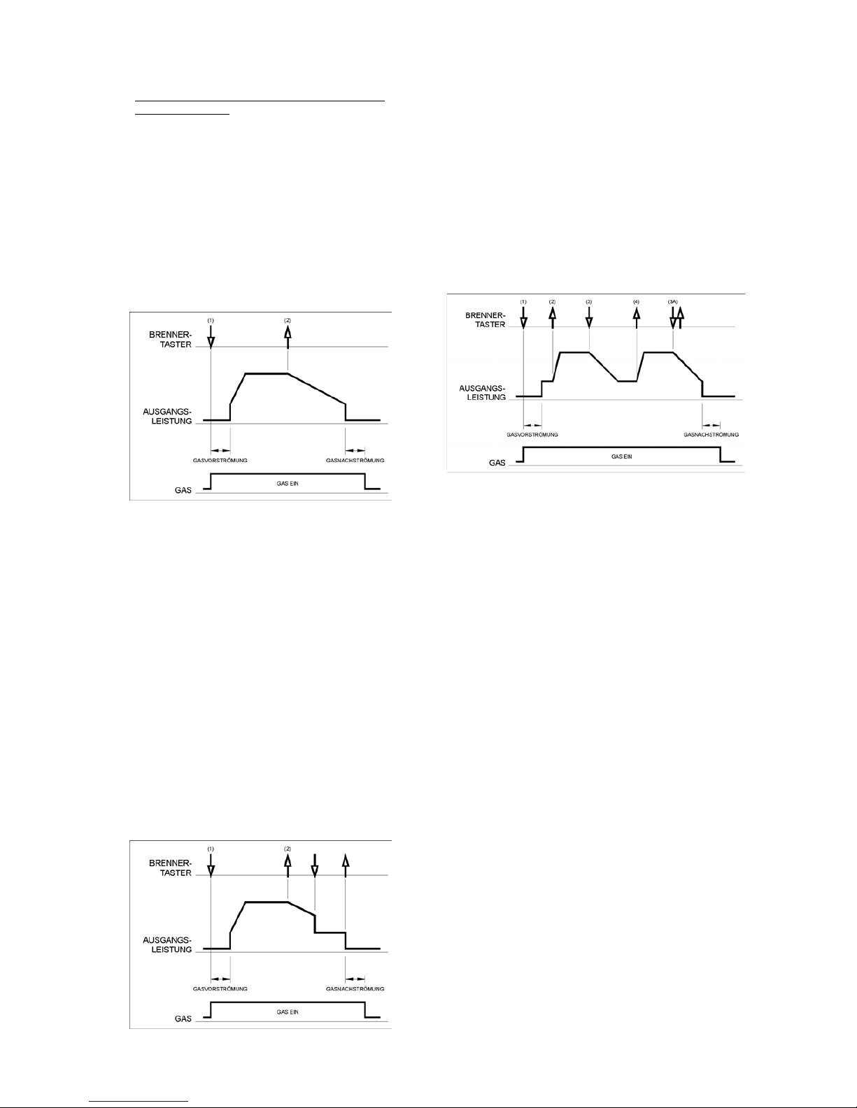
C-6
T. Einstellung der Gasnachströmzeit (nur V205-T /
V270-T / V405-T): Im WIG-Betrieb regelt dieser
Drehknopf die Nachströmzeit des Schutzgases von
0,5 bis 30 Sekunden. Die Gasvorströmzeit beträgt
immer 0,5 Sekunden. Im Stabelektrodenbetrieb
wird diese Funktion nicht verwendet.
WIG-Brennertaster Schaltfunktionen
Das WIG-Schweißen kann entweder im 2-Takt- oder 4Takt-Betrieb erfolgen. Weitere Details dieser Vorgänge
werden in den nachfolgenden Abschnitten beschrieben.
2-Takt-Betrieb (WIG)
Bei Auswahl der Funktionen WIG-Schweißen und 2Takt-Betrieb, ergeben sich die nachfolgend
beschriebenen Funktionsabläufe.
1. Drücken und halten Sie den Taster am WIGBrenner, um den folgenden Ablauf zu starten: Die
Maschine wird das Gasmagnetventil öffnen, um das
Ausströmen von Schutzgas zu starten. Nach Ablauf
der Gasvorströmzeit, durch welche die noch im
Gasschlauch verbliebene Luft herausgespült wird,
schaltet sich der Anfangsstrom der Maschine ein.
Der Lichtbogen startet nun je nach vorab gewählter
Betriebsart (Lift-Arc oder HF). Unmittelbar nach
dem Zünden des Lichtbogens steigt der Strom
innerhalb eines bestimmten Zeitabschnitts
(Stromanstiegzeit) linear auf den Schweißstrom an.
2. Lösen Sie den Brennertaster, um den
Schweißvorgang zu beenden. Die Maschine wird
nun den Ausgangsstrom entsprechend der vorab
eingestellten Stromabsenkzeit herunterregeln, bis
der Endkrater-Strom erreicht ist, und die Maschine
schließlich ganz abschaltet.
Nachdem der Lichtbogen erloschen ist, bleibt das
Gasventil noch geöffnet, um weiter Schutzgas zur
heißen Elektrode und zum Werkstück strömen zu
lassen.
Wie im Bild oben dargestellt, ist es außerdem möglich,
den Brennertaster während der Stromabsenkphase ein
zweites Mal zu drücken und zu halten, um die
Absenkphase zu beenden, und den Ausgangsstrom auf
dem Wert des Endkraterfüllstroms zu halten. Wird dann
der Brennertaster gelöst, schaltet die Maschine den
Ausgangsstrom ab, und die eingestellte
Gasnachstromzeit beginnt. Dieser Funktionsablauf mit
deaktivierter Durchstartfunktion im 2-Taktbetrieb
entspricht den Werkseinstellungen der Anlage bei
Auslieferung.
4-Takt-Betrieb (WIG)
Bei Auswahl der Funktionen WIG-Schweißen und 4Takt-Betrieb, ergeben sich die nachfolgend
beschriebenen Funktionsabläufe.
1. Drücken und halten Sie den Taster am WIGBrenner, um den folgenden Ablauf zu starten: Die
Maschine wird das Gasmagnetventil öffnen, um das
Ausströmen von Schutzgas zu starten. Nach Ablauf
der Gasvorströmzeit, durch welche die noch im
Gasschlauch verbliebene Luft herausgespült wird,
schaltet sich der Anfangsstrom der Maschine ein.
Der Lichtbogen startet nun je nach vorab gewählter
Betriebsart (Lift-Arc oder HF). Nachdem der
Lichtbogen gezündet wurde, verbleibt zunächst die
Stromstärke auf dem Wert des Start-Stroms. Dieser
Zustand kann so lange oder oder so kurz wie nötig
beibehalten werden.
Falls kein Start-Strom benötigt wird, halten Sie nicht
wie zu Anfang dieses Abschnitts beschrieben den
Brennertaster dauerhaft gedrückt. In diesem Falle
wird dann die Maschine automatisch von Schritt 1.
auf Schritt 2. übergehen, nachdem der Lichtbogen
gezündet wurde.
2. Beim Lösen des Brennertasters beginnt die Phase
des Stromanstiegs. Unmittelbar nach dem Zünden
des Lichtbogens steigt der Strom innerhalb eines
bestimmten Zeitabschnitts (Stromanstiegszeit)
linear auf den Schweißstrom an.
3. Drücken und halten Sie den Brennertaster, wenn
der eigentliche Schweißvorgang beendet werden
soll. Die Maschine wird nun den Ausgangsstrom
entsprechend der vorab eingestellten
Stromabsenkzeit herunterregeln bis der EndkraterStrom erreicht ist. Dieser Endkrater-Strom kann so
lange oder so kurz wie nötig gehalten werden.
In dieser Phase verfügt die Maschine über eine
automatische Durchstartfunktion, so dass der
Schweißvorgang anschließend fortgesetzt wird,
sobald der Taster wieder gelöst wird. Dieser
Funktionsablauf mit aktivierter Durchstartfunktion im
4-Takt-Betrieb entspricht den Werkseinstellungen
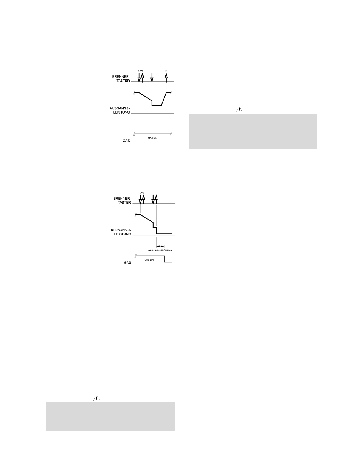
C-7
der Anlage bei Auslieferung. Wenn der
Schweißvorgang vollständig abgeschlossen ist,
gehen Sie abweichend von den Beschreibungen in
Abschnitt 3. wie folgt vor:
3A. Drücken Sie kurz den Brennertaster und
lösen Sie ihn
sofort wieder.
Die Maschine
wird nun den
Ausgangsstro
m
entsprechend
der vorab
eingestellten
Stromabsenkz
eit
herunterregeln
, bis der
EndkraterStrom erreicht ist, und die Maschine schließlich
ganz abschaltet. Nachdem der Lichtbogen
erloschen ist, startet die vorab eingestellte
Gasnachströmzeit.
4. Lösen Sie den Brennertaster. Der Ausgangsstrom
wird erneut auf den Wert des Schweißstroms
ansteigen (wie in
Schritt 2.), um den
Schweißvorgang
fortzusetzen. Wenn
der eigentliche
Schweißvorgang
beendet ist, gehen
Sie zu Schritt 3.
Wie auf diesem Bild
dargestellt, ist es
möglich, nachdem der
Brennertaster wie bei
Schritt 3A schnell
gedrückt und sofort wieder gelöst wird, den
Brennertaster ein zweites Mal zu drücken und zu halten,
um die Stromabsenkphase zu beenden und den
Ausgangsstrom auf dem Wert des Endkraterfüllstroms
zu halten. Wird nun der Brennertaster wieder gelöst,
steigt die Stromstärke wieder auf den Wert des
Schweißstroms an, wie bei Schritt 4, um den
Schweißvorgang fortzusetzen. Wenn der eigentliche
Schweißvorgang abgeschlossen ist, fahren Sie wie bei
Schritt 3. fort.
Wie auf diesem Bild dargestellt, ist es außerdem
möglich, nachdem der Brennertaster kurz gedrückt und
sofort wieder gelöst wurde (wie bei Schritt 3A
beschrieben), den Brennertaster ein zweites Mal kurz zu
drücken und sofort wieder zu lösen, um die
Stromabsenkphase abzubrechen und den
Schweißprozess zu beenden.
04/03
Wartung
WARNUNG
Für Wartung und Reparatur des Gerätes konsultieren
Sie bitte Ihren Fachhändler oder die Lincoln Electric.
Eine unsachgemäß durchgeführte Wartung oder
Reparatur durch eine nicht qualifizierte Person führt zum
Erlöschen der Garantie.
Die Häufigkeit der Wartungen hängt unter anderem auch
von der Arbeitsumgebung der Maschine ab. Eventuelle
Schäden müssen sofort gemeldet werden.
x Prüfen Sie Kabel und Stecker auf Beschädigungen.
Tauschen Sie diese aus, wenn notwendig.
x Halten Sie die Maschine sauber. Verschmutzungen
am Gehäuse insbesondere an den Luftein- und
Auslässen beseitigen Sie mit einem weichen
trockenen Tuch.
WARNUNG
Maschine nicht öffnen und nichts in die Öffnungen
stecken. Die Maschine muß während der Durchführung
der Wartungsarbeiten von der Energieversorgung
getrennt sein. Nach jeder Reparatur sind geeignete
Tests durchzuführen, um die Betriebssicherheit zu
überprüfen.
 Loading...