

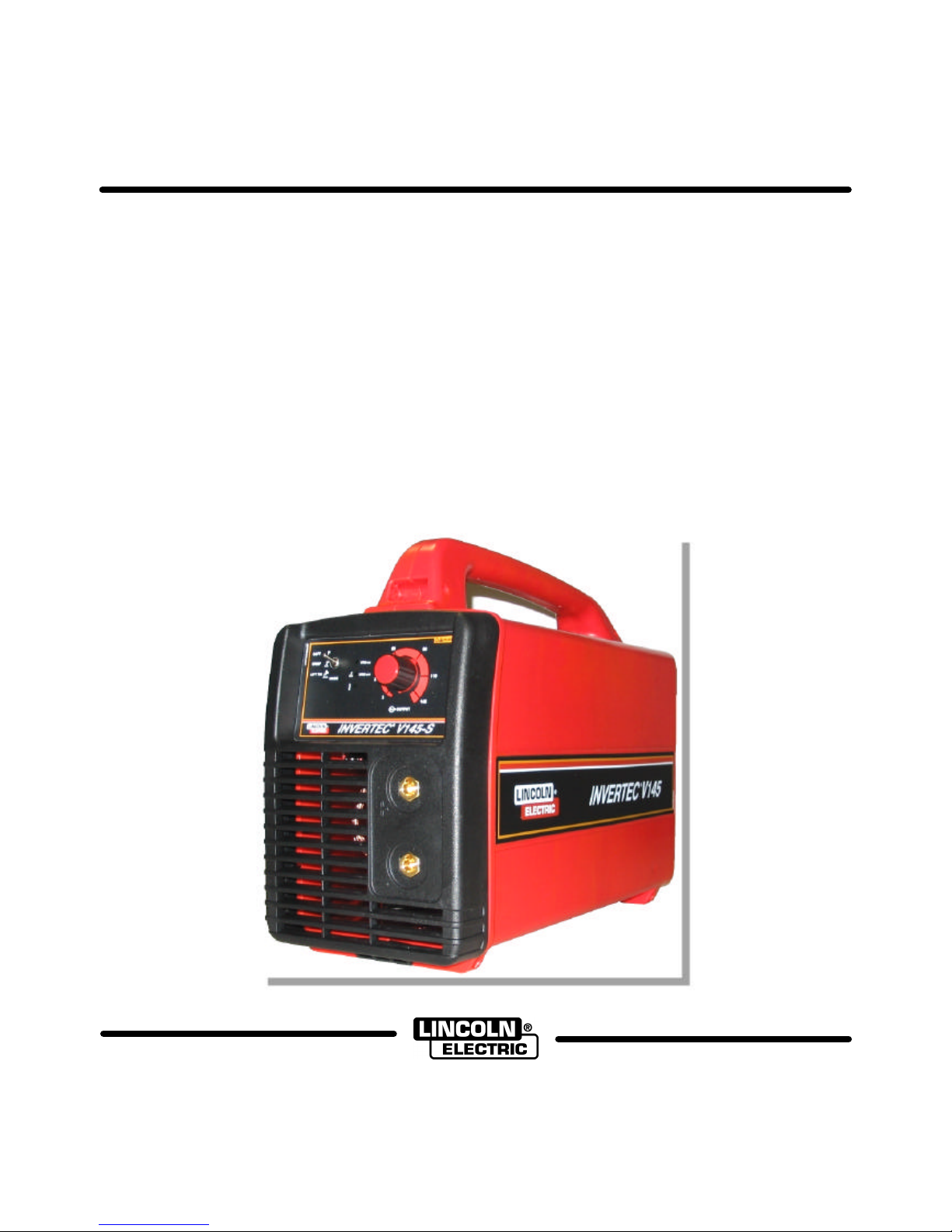
INVERTEC V145-S Operator's Manual
IM2001
03/2005
Rev. 2
INVERTEC V145-S
OPERATOR’S MANUAL
MANUALE OPERATIVO
BEDIENUNGSANLEITUNG
MANUAL DE INSTRUCCIONES
MANUEL D'UTILISATION
BRUKSANVISNING OG DELELISTE
GEBRUIKSAANWIJZING
BRUKSANVISNING
INSTRUKCJA OBSLUGI
LINCOLN ELECTRIC ITALIA S.r.l
Via Fratelli Canepa 8, 16010 Serrà Riccò (GE), Italia
www.lincolnelectriceurope.com
II
Declaration of conformity
Dichiarazione di conformità
Konformitätserklärung
Declaración de conformidad
Déclaration de conformité
Samsvars erklæring
Verklaring van overeenstemming
Försäkran om överensstämmelse
Deklaracja zgodnosci
LINCOLN ELECTRIC ITALIA S.r.l.
Declares that the welding machine:
Dichiara che Il generatore per saldatura tipo:
Erklärt, daß die Bauart der Maschine:
Declara que el equipo de soldadura:
Déclare que le poste de soudage:
Bekrefter at denne sveisemaskin:
Verklaart dat de volgende lasmachine:
Försäkrar att svetsomriktaren:
Deklaruje, ze spawalnicze zródlo energii:
INVERTEC V145-S
conforms to the following directives:
è conforme alle seguenti direttive:
den folgenden Bestimmungen entspricht:
es conforme con las siguientes directivas:
est conforme aux directives suivantes:
er i samsvar med følgende direktiver:
overeenkomt conform de volgende richtlijnen:
överensstämmer med följande direktiv:
spelnia nastepujace wytyczne:
73/23/CEE, 89/336/CEE
and has been designed in compliance with the following
standards:
ed è stato progettato in conformità alle seguenti norme:
und in Übereinstimmung mit den nachstehenden normen
hergestellt wurde:
y ha sido diseñado de acuerdo con las siguientes
normas:
et qu'il a été conçu en conformité avec les normes:
og er produsert og testet iht. følgende standarder:
en is ontworpen conform de volgende normen:
och att den konstruerats i överensstämmelse med
följande standarder:
i ze zostalo zaprojektowane zgodnie z wymaganiami
nastepujacych norm:
EN 60974-1, EN 60974-10
Dario Gatti
European Engineering Director Machines
LINCOLN ELECTRIC ITALIA S.r.l., Via Fratelli Canepa 8, 16010 Serra Riccò (GE), Italia
11/04
III
02/05
THANKS! For having choosen the QUALITY of the Lincoln Electric products.
• Please Examine Package and Equipment for Damage. Claims for material damaged in shipment must be notified
immediately to the dealer.
• For future reference record in the table below your equipment identification information. Model Name, Code &
Serial Number can be found on the machine rating plate.
GRAZIE! Per aver scelto la QUALITÀ dei prodotti Lincoln Electric.
• Esamini Imballo ed Equipaggiamento per rilevare eventuali danneggiamenti. Le richieste per materiali danneggiati
dal trasporto devono essere immediatamente notificate al rivenditore.
• Per ogni futuro riferimento, compilare la tabella sottostante con le informazioni di identificazione equipaggiamento.
Modello, Codice (Code) e Matricola (Serial Number) sono reperibili sulla targa dati della macchina.
VIELEN DANK! Dass Sie sich für ein QUALITÄTSPRODUKT von Lincoln Electric entschieden haben.
• Bitte überprüfen Sie die Verpackung und den Inhalt auf Beschädigungen. Transportschäden müssen sofort dem
Händler gemeldet werden.
• Damit Sie Ihre Gerätedaten im Bedarfsfall schnell zur Hand haben, tragen Sie diese in die untenstehende Tabelle
ein. Typenbezeichnung, Code- und Seriennummer finden Sie auf dem Typenschild Ihres Gerätes.
GRACIAS! Por haber escogido los productos de CALIDAD Lincoln Electric.
• Por favor, examine que el embalaje y el equipo no tengan daños. La reclamación del material dañado en el
transporte debe ser notificada inmediatamente al proveedor.
• Para un futuro, a continuación encontrará la información que identifica a su equipo. Modelo, Code y Número de
Serie los cuales pueden ser localizados en la placa de características de su equipo.
MERCI! Pour avoir choisi la QUALITÉ Lincoln Electric.
• Vérifiez que ni l’équipement ni son emballage ne sont endommagés. Toute réclamation pour matériel
endommagé doit être immédiatement notifiée à votre revendeur.
• Notez ci-dessous toutes les informations nécessaires à l’identification de votre équipement. Le nom du Modèle
ainsi que les numéros de Code et Série figurent sur la plaque signalétique de la machine.
TAKK! For at du har valgt et KVALITETSPRODUKT fra Lincoln Electric.
• Kontroller emballsjen og produktet for feil eller skader. Eventuelle feil eller transportskader må umiddelbart
rapporteres dit du har kjøpt din maskin.
• For fremtidig referanse og for garantier og service, fyll ut den tekniske informasjonen nedenfor i dette avsnittet.
Modell navn, Kode & Serie nummer finner du på den tekniske platen på maskinen.
BEDANKT! Dat u gekozen heeft voor de KWALITEITSPRODUCTEN van Lincoln Electric.
• Controleert u de verpakking en apparatuur op beschadiging. Claims over transportschade moeten direct aan de
dealer of aan Lincoln electric gemeld worden.
• Voor referentie in de toekomst is het verstandig hieronder u machinegegevens over te nemen. Model Naam,
Code & Serienummer staan op het typeplaatje van de machine.
TACK! För att ni har valt en KVALITETSPRODUKT från Lincoln Electric.
• Vänligen kontrollera förpackning och utrustning m.a.p. skador. Transportskador måste omedelbart anmälas till
återförsäljaren eller transportören.
• Notera informationen om er utrustnings identitet i tabellen nedan. Modellbeteckning, code- och serienummer hittar
ni på maskinens märkplåt.
DZIEKUJEMY! Za docenienie JASKOSCI produktów Lincoln Electric.
• Prosze sprawdzic czy opakownie i sprzet nie sa uszkodzone. Reklamacje uszkodzen powstalych podczas
transportu musza byc natychmiast zgloszone do dostawcy (dystrybutora).
• Dla ulatwienia prosimy o zapisanie na tej stronie danych identyfikacyjnych wyrobów. Nazwa modelu, Kod i Numer
Seryjny, które mozecie Panstwo znalezc na tabliczce znamionowej wyrobu.
Model Name, Modello, Typenbezeichnung, Modelo, Nom du modèle, Modell navn, Model Naam, Modellbeteckning,
Nazwa modelu:
………………...…………………………….…………………………………………………………………………………………..
Code & Serial number, Code (codice) e Matricola, Code- und Seriennummer, Code y Número de Serie, Numéros de
Code et Série, Kode & Serie nummer, Code en Serienummer, Code- och Serienummer, Kod i numer Seryjny:
………………….………………………………………………..
…………………………………………………….……………..
Date & Where Purchased, Data e Luogo d’acquisto, Kaufdatum und Händler, Fecha y Nombre del Proveedor, Lieu et
Date d’acquisition, Kjøps dato og Sted, Datum en Plaats eerste aankoop, Inköpsdatum och Inköpsställe, Data i Miejsce
zakupu:
…………………………………………………………………...
……………………….…………………………………………..

IV
ENGLISH INDEX
Safety .......................................................................................................................................................................... A-1
Installation and Operator Instructions..........................................................................................................................A-2
Electromagnetic Compatibility (EMC) .......................................................................................................................... A-4
Technical Specifications.............................................................................................................................................. A-5
INDICE ITALIANO
Sicurezza.....................................................................................................................................................................B-1
Installazione e Istruzioni Operative..............................................................................................................................B-2
Compatibilità Elettromagnetica (EMC).........................................................................................................................B-4
Specifiche Tecniche..................................................................................................................................................... B-5
INHALTSVERZEICHNIS DEUTSCH
Sicherheitsmaßnahmen / Unfallschutz ........................................................................................................................ C-1
Installation und Bedienungshinweise...........................................................................................................................C-2
Elektromagnetische Verträglichkeit (EMC) .................................................................................................................. C-4
Technische Daten........................................................................................................................................................ C-5
INDICE ESPAÑOL
Seguridad .................................................................................................................................................................... D-1
Instalación e Instrucciones de Funcionamiento........................................................................................................... D-2
Compatibilidad Electromagnética (EMC).....................................................................................................................D-4
Especificaciones Técnicas........................................................................................................................................... D-5
INDEX FRANÇAIS
Sécurité ....................................................................................................................................................................... E-1
Installation et Instructions d'Utilisation......................................................................................................................... E-2
Compatibilité Electromagnétique (CEM)...................................................................................................................... E-4
Caractéristiques Techniques ....................................................................................................................................... E-5
NORSK INNHOLDSFORTEGNELSE
Sikkerhetsregler............................................................................................................................................................F-1
Installasjon og Brukerinstruksjon..................................................................................................................................F-2
Elektromagnetisk Kompatibilitet (EMC).........................................................................................................................F-4
Tekniske Spesifikasjoner..............................................................................................................................................F-5
NEDERLANDSE INDEX
Veiligheid.....................................................................................................................................................................G-1
Installatie en Bediening................................................................................................................................................G-2
Elektromagnetische Compatibiliteit (EMC)...................................................................................................................G-4
Technische Specificaties .............................................................................................................................................G-5
SVENSK INNEHÅLLSFÖRTECKNING
Säkerhetsanvisningar..................................................................................................................................................H-1
Instruktioner för Installation och Handhavande............................................................................................................ H-2
Elektromagnetisk Kompatibilitet (EMC)........................................................................................................................H-4
Tekniska Specifikationer..............................................................................................................................................H-5
SKOROWIDZ POLSKI
Bezpieczenstwo Uzytkowania........................................................................................................................................I-1
Instrukcja Instalacji i Eksploatacji................................................................................................................................... I-2
Kompatybilnosc Elektromagnetyczna (EMC).................................................................................................................I-5
Dane Techniczne...........................................................................................................................................................I-6
Spare Parts, Parti di Ricambio, Ersatzteile, Lista de Piezas de Recambio, Pièces de Rechange, Deleliste, Reserve
Onderdelen, Reservdelar, Wykaz Czesci Zamiennych....................................................................................................1
Electrical Schematic, Schema Elettrico, Elektrische Schaltpläne, Esquema Eléctrico, Schéma Electrique, Elektrisk
Skjema, Elektrisch Schema, Elektriskt Kopplingsschema, Schemat Elektryczny............................................................4
Accessories, Accessori, Zubehör, Accesorios, Accessoires, Tilleggsutstyr, Accessores, Tillbehör, Akcesoria...............5
A-1
Safety
11/04
WARNING
This equipment must be used by qualified personnel. Be sure that all installation, operation, maintenance and repair
procedures are performed only by qualified person. Read and understand this manual before operating this equipment.
Failure to follow the instructions in this manual could cause serious personal injury, loss of life, or damage to this
equipment. Read and understand the following explanations of the warning symbols. Lincoln Electric is not responsible
for damages caused by improper installation, improper care or abnormal operation.
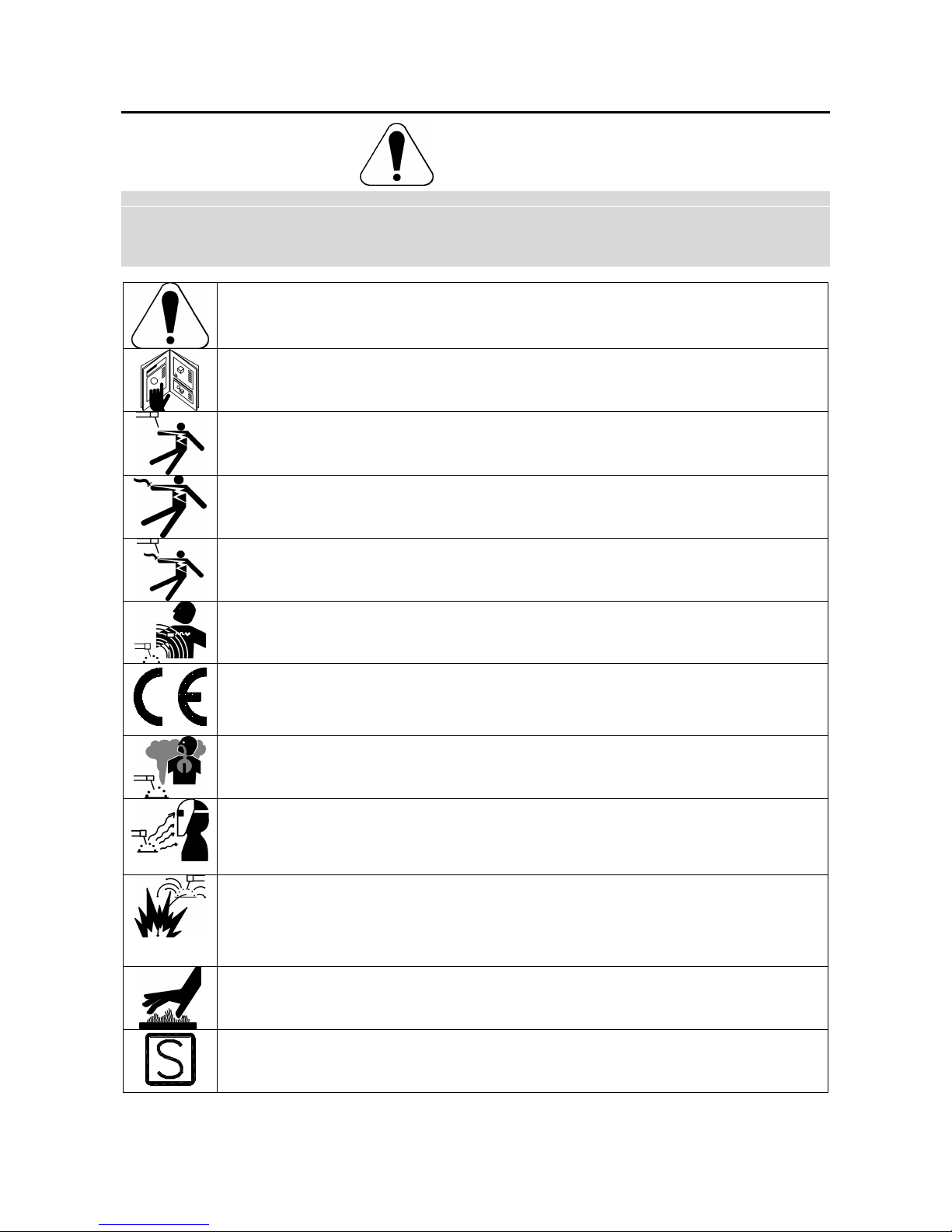
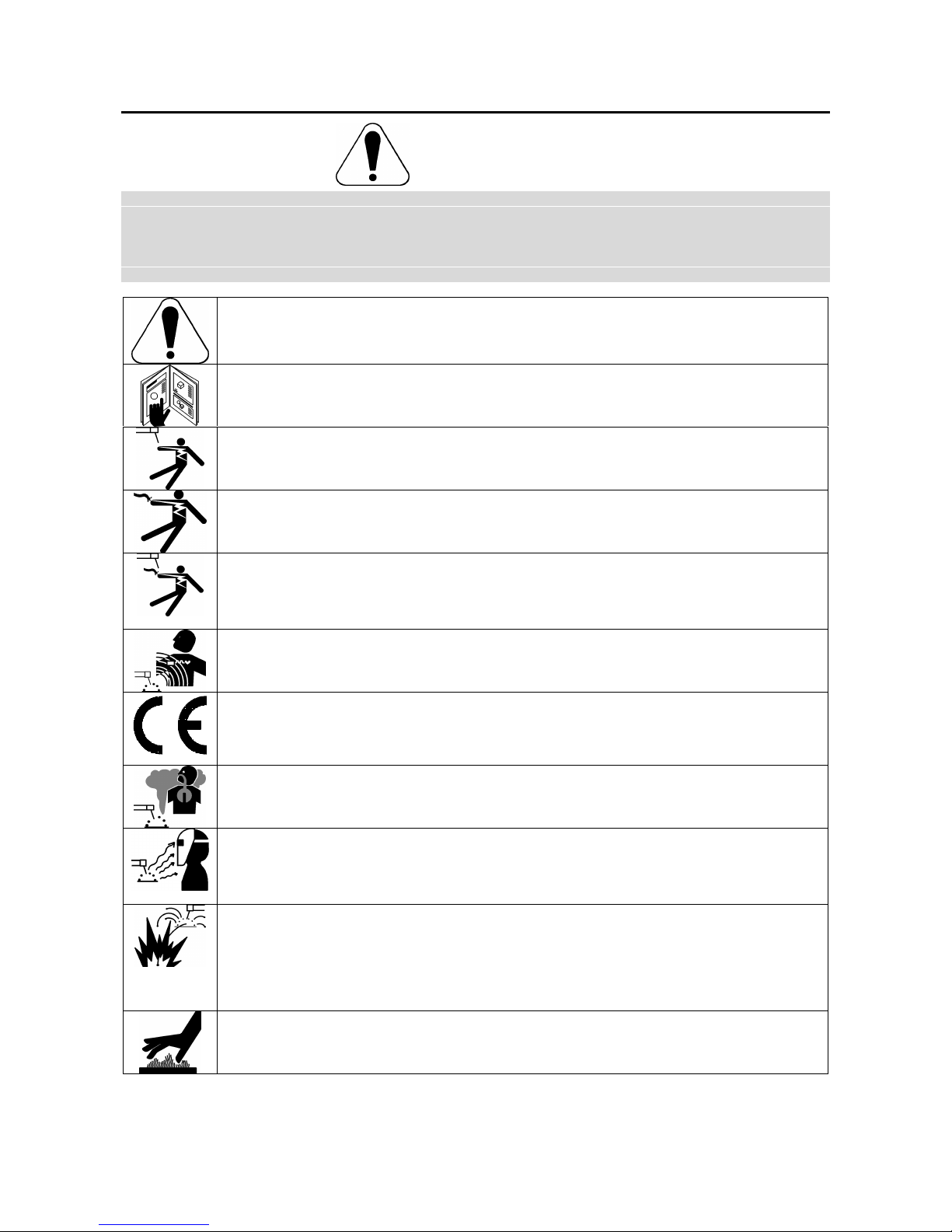
WARNING: This symbol indicates that instructions must be followed to avoid serious personal injury,
loss of life, or damage to this equipment. Protect yourself and others from possible serious injury or
death.
READ AND UNDERSTAND INSTRUCTIONS: Read and understand this manual before operating
this equipment. Arc welding can be hazardous. Failure to follow the instructions in this manual could
cause serious personal injury, loss of life, or damage to this equipment.
ELECTRIC SHOCK CAN KILL: Welding equipment generates high voltages. Do not touch the
electrode, work clamp, or connected work pieces when this equipment is on. Insulate yourself from
the electrode, work clamp, and connected work pieces.
ELECTRICALLY POWERED EQUIPMENT: Turn off input power using the disconnect switch at the
fuse box before working on this equipment. Ground this equipment in accordance with local electrical
regulations.
ELECTRICALLY POWERED EQUIPMENT: Regularly inspect the input, electrode, and work clamp
cables. If any insulation damage exists replace the cable immediately. Do not place the electrode
holder directly on the welding table or any other surface in contact with the work clamp to avoid the
risk of accidental arc ignition.
ELECTRIC AND MAGNETIC FIELDS MAY BE DANGEROUS: Electric current flowing through any
conductor creates electric and magnetic fields (EMF). EMF fields may interfere with some
pacemakers, and welders having a pacemaker shall consult their physician before operating this
equipment.
CE COMPLIANCE: This equipment complies with the European Community Directives.
FUMES AND GASES CAN BE DANGEROUS: Welding may produce fumes and gases hazardous to
health. Avoid breathing these fumes and gases. To avoid these dangers the operator must use
enough ventilation or exhaust to keep fumes and gases away from the breathing zone.
ARC RAYS CAN BURN: Use a shield with the proper filter and cover plates to protect your eyes from
sparks and the rays of the arc when welding or observing. Use suitable clothing made from durable
flame-resistant material to protect you skin and that of your helpers. Protect other nearby personnel
with suitable, non-flammable screening and warn them not to watch the arc nor expose themselves to
the arc.
WELDING SPARKS CAN CAUSE FIRE OR EXPLOSION: Remove fire hazards from the welding
area and have a fire extinguisher readily available. Welding sparks and hot materials from the welding
process can easily go through small cracks and openings to adjacent areas. Do not weld on any
tanks, drums, containers, or material until the proper steps have been taken to insure that no
flammable or toxic vapors will be present. Never operate this equipment when flammable gases,
vapors or liquid combustibles are present.
WELDED MATERIALS CAN BURN: Welding generates a large amount of heat. Hot surfaces and
materials in work area can cause serious burns. Use gloves and pliers when touching or moving
materials in the work area.
SAFETY MARK: This equipment is suitable for supplying power for welding operations carried out in
an environment with increased hazard of electric shock.
A-2
CYLINDER MAY EXPLODE IF DAMAGED: Use only compressed gas cylinders containing the
correct shielding gas for the process used and properly operating regulators designed for the gas and
pressure used. Always keep cylinders in an upright position securely chained to a fixed support. Do
not move or transport gas cylinders with the protection cap removed. Do not allow the electrode,
electrode holder, work clamp or any other electrically live part to touch a gas cylinder. Gas cylinders
must be located away from areas where they may be subjected to physical damage or the welding
process including sparks and heat sources.
Installation and Operator Instructions
Read this entire section before installation or operation
of the machine.
Location and Environment
This machine can operate in harsh environments.
However, it is important that simple preventative
measures are followed to assure long life and reliable
operation:
• Do not place or operate this machine on a surface
with an incline greater than 15° from horizontal.
• Do not use this machine for pipe thawing.
• This machine must be located where there is free
circulation of clean air without restrictions for air
movement to and from the air vents. Do not cover
the machine with paper, cloth or rags when
switched on.
• Dirt and dust that can be drawn into the machine
should be kept to a minimum.
• This machine has a protection rating of IP23. Keep
it dry when possible and do not place it on wet
ground or in puddles.
• Locate the machine away from radio controlled
machinery. Normal operation may adversely affect
the operation of nearby radio controlled machinery,
which may result in injury or equipment damage.
Read the section on electromagnetic compatibility in
this manual.
• Do not operate in areas with an ambient
temperature greater than 40°C.
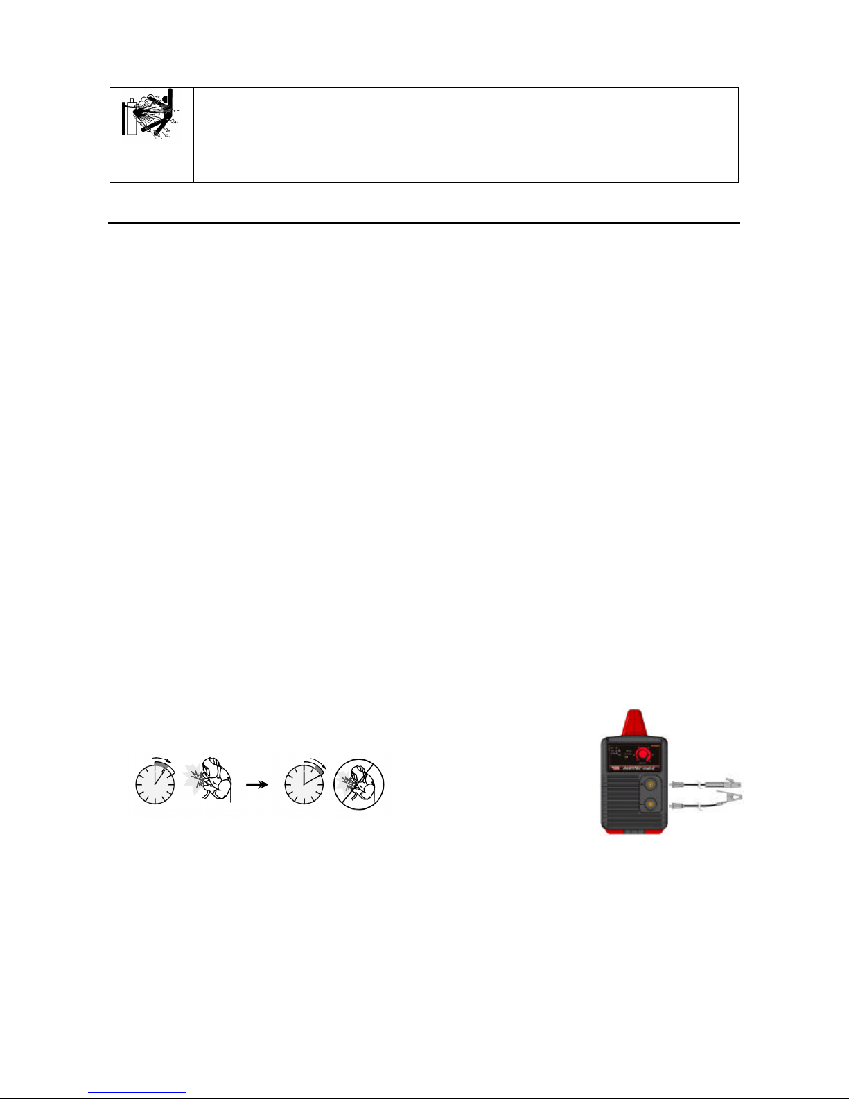
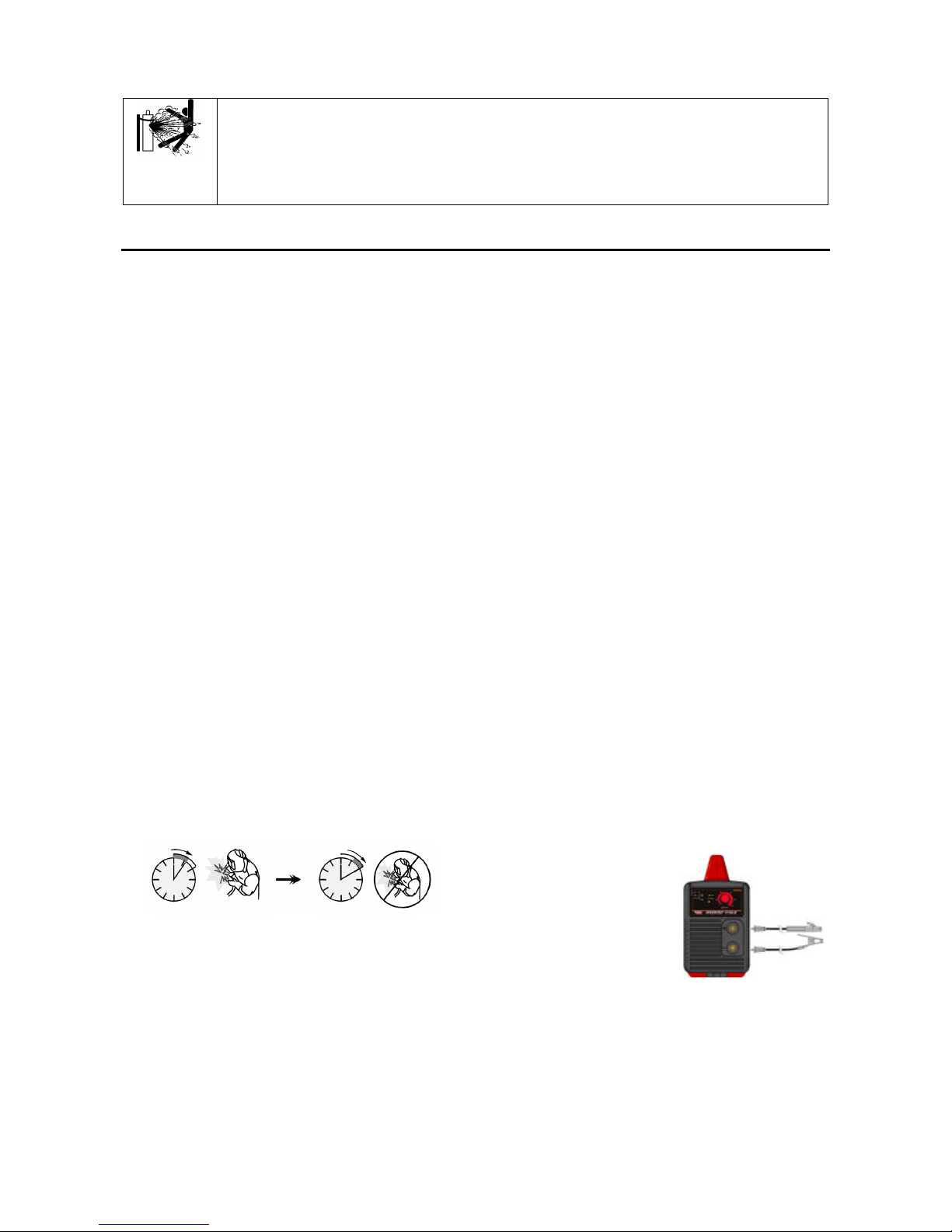
Duty Cycle
The duty cycle of a welding machine is the percentage of
time in a 10 minute cycle at which the welder can
operate the machine at rated welding current.
Example: 35% duty cycle:
Welding for 3.5 minutes. Break for 6.5 minutes.
Refer to the Technical Specification section for more
information about the machine rated duty cycles.
Input Supply Connection
Check the input voltage, phase, and frequency supplied
to this machine before turning it on. The allowable input
voltage is indicated in the technical specification section
of this manual and on the rating plate of the machine.
Be sure that the machine is grounded.
Make sure the amount of power available from the input
connection is adequate for normal operation of the
machine. The fuse rating and cable sizes are both
indicated in the technical specification section of this
manual.
This machine is designed to operate on engine driven
generators as long as the 230Vac auxiliary can supply
adequate power as indicated in the technical
specification section of this manual. The auxiliary supply
of the generator must also meet the following conditions:
• Vac peak voltage: below 410V.
• Vac frequency: in the range of 50 and 60 Hertz.
• RMS voltage of the AC waveform: 230Vac ± 15%.
It is important to check these conditions because many
engine driven generators produce high voltage spikes.
Operation of this machine with engine driven generators
not conforming to these conditions is not recommended
and may damage the machine.
Output Connections
A quick disconnect system using Twist-MateTM cable
plugs is used for the welding cable connections. Refer
to the following sections for more information on
connecting the machine for operation of stick welding
(MMA) or TIG welding.
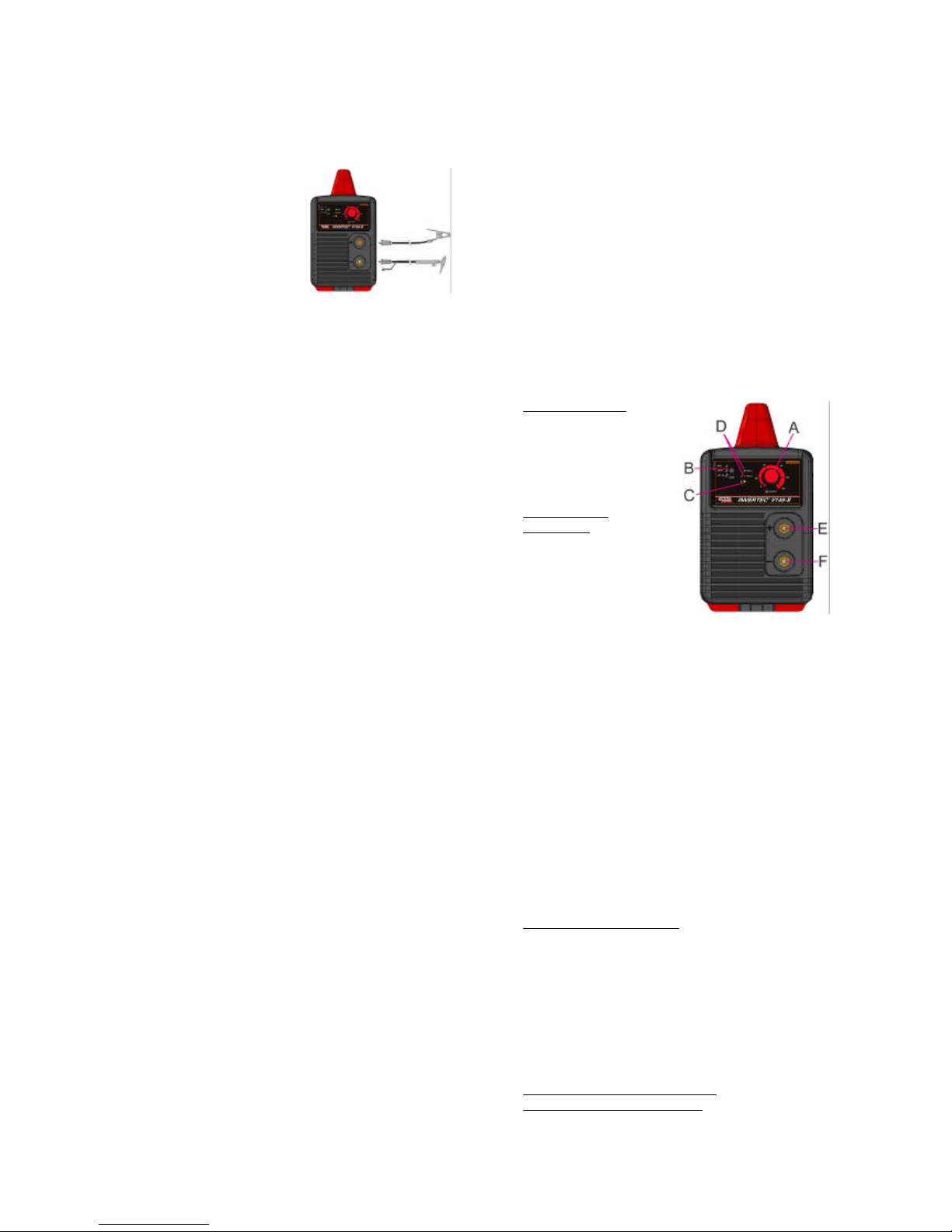
Stick Welding (MMA)
First determine the proper electrode polarity for the
electrode to be used. Consult the electrode data for this
information. Then connect the output cables to the
output terminals of the machine for the selected polarity.
Shown here is the connection method for DC(+) welding.
Connect the electrode
cable to the (+) terminal
and the work clamp to the
(-) terminal. Insert the
connector with the key
lining up with the keyway
and rotate approximately ¼
turn clockwise. Do not over
tighten.
For DC(-) welding, switch the cable connections at the
machine so that the electrode cable is connected to (-)
and the work clamp is connected to (+).
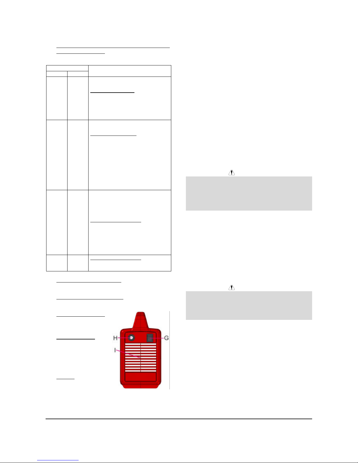
TIG Welding
This machine does not include a TIG torch necessary for
TIG welding, but one may be purchased separately.
Refer to the accessories section for more information.
Most TIG welding is done with DC(-) polarity shown
here. If DC(+) polarity is necessary switch the cable
connections at the machine.

A-3
Connect the torch cable to
the (-) terminal of the
machine and the work
clamp to the (+) terminal.
Insert the connector with
the key lining up with the
keyway and rotate
approximately ¼ turn
clockwise. Do not over
tighten. Finally, connect
the gas hose to the gas regulator on the cylinder of gas
to be used.
VRD: Voltage Reduction Device
This machine is provided by an internal VRD (Voltage
Reduction Device) circuitry: this device reduces the
voltage at the output leads. The VRD is automatically
enabled / disabled by the machine. The factory default
voltage is:
V145-S CE: 75 Vdc
V145-S CE (12V): 12 Vdc
V145-S AUSTRALIA: 12 Vdc
Refer to the section below for more details.
Auto Adaptive Arc Force (with MMA
welding)
During MMA welding is activated the function Auto
Adaptive Arc Force that increases temporary the output
current, used to clear intermittent connections between
the electrode and the weld puddle that occur during stick
welding.
This is an active control feature that guarantees the best
arrangement between the arc stability and spatter
presence. The feature "Auto Adaptive Arc Force" has
instead of a fixed or manual regulation, an automatic and
multilevel setting: its intensity depends by the output
voltage and it is calculated in real time by the
microprocessor where are also mapped the Arc Force
levels. The control measure in each instant the output
voltage, compare with the mapped levels and it
determines the amount of the peak of current to apply;
that value is enough to breaks the metal drop that is
being transferred from the electrode to the workpiece as
to guarantee the arc stability, but not too high to avoid
spatters around the welding puddle. That means:
• Electrode / workpiece sticking prevention, also with
low current values.
• Spatters reduction.
The welding operations are simplified and the welded
joins looks better, also if not brushed after the welding.
This feature is available in the Soft Stick and Crisp
Stick operating modes and can be selected by the
operator and it allows to weld with the characteristics
more suitable at the electrode type and welding
conditions. The Crisp Stick feature also increases the
Hot Start action, facilitating the arc striking.
With the MMA welding are also enabled the following
features:
• Hot Start: This is a temporary increase in the initial
welding current. This helps ignite the arc quickly
and reliably.
• Anti-Sticking: This is a function that decreases the
output current of the machine to a low level when
the operator makes an error and sticks the electrode
to the work piece. This decrease in current allows
the operator to remove the electrode from the
electrode holder without creating large sparks that
can damage the electrode holder.
Refer to the section below for more details.
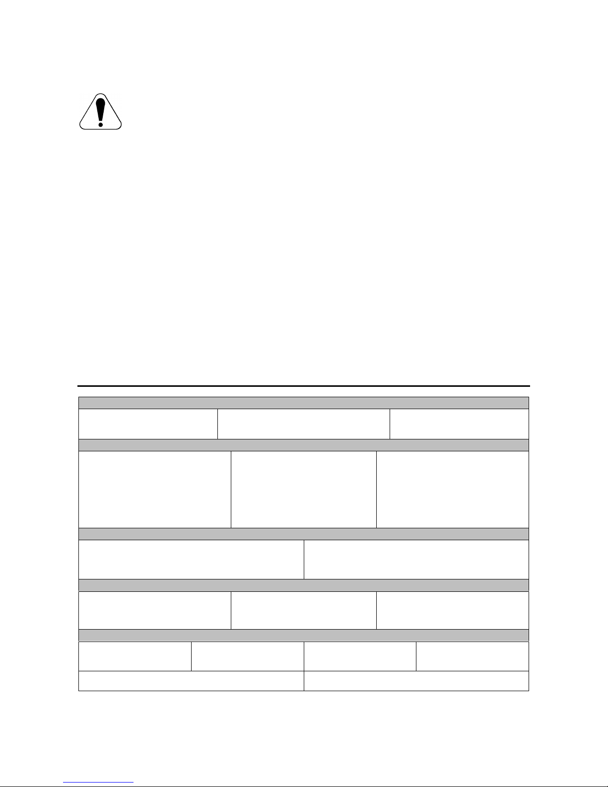
Controls and Operational Features
A. Output Current
Knob:
Potentiometer used
to set the output
current used during
welding, from 5A to
145A.
B. Welding Mode
Switch: With three
positions, controls
the welding mode of
the machine: two for
Stick welding (Soft
and Crisp) and one
for Lift TIG welding.
• Soft Stick: For a welding with a low spatter
presence.
• Crisp Stick: For an aggressive welding, with an
increased Arc stability.
• Lift TIG: When the mode switch is in the Lift
TIG position, the stick welding functions are
disabled and the machine is ready for Lift TIG
welding. Lift TIG is a method of starting a TIG
weld by first pressing the TIG torch electrode
on the work piece in order to create a low
current short circuit. Then, the electrode is
lifted from the work piece to start the TIG arc.
C. Thermal LED: This indicator will turn on when the
machine is overheated and the output has been
disabled. This normally occurs when the duty cycle
of the machine has been exceeded. Leave the
machine on to allow the internal components to
cool. When the indicator turns off, normal operation
is again possible.
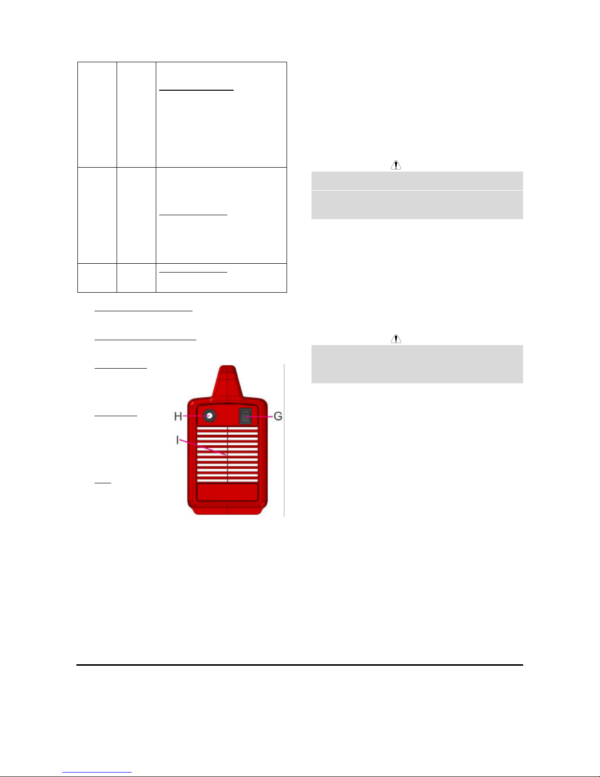
D. Power On/Off & VRD (Voltage Reduction Device)
LEDs: These LEDs (one green and one red)
operates as described in the table below:
LED status
Green Red
Function
ON OFF
The machine is turned ON.
VRD ON condition: The machine
is at idle (no-welding time) and
the VRD device is enabled. No
current at the output leads; the
voltage has reached a value
under the VRD limit.
A-4
OFF ON
The machine is turned ON.
VRD OFF condition: A welding is
running and the VRD device is
disabled. Presence of current at
the output leads, the voltage
value may be over the VRD limit.
This permanent LED condition,
showed at idle (no-welding time),
indicates a machine damage.
OFF OFF
The machine is turned OFF
and/or the input cord could be
disconnected from the mains.
ERROR condition: With the
Power Switch turned ON and the
input cord properly connected to
a “live” main supply, this LED
condition indicates a machine
damage.
ON ON
ERROR condition: This LED
condition indicates a machine
damage.
E. Positive Quick Disconnect: Positive output
connector for the welding circuit.
F. Negative Quick Disconnect: Negative output
connector for the welding circuit.
G. Power Switch: It
turns ON / OFF
the input power to
the machine.
H. Input cable: This
machine is
provided with a
plugged input
cord. Connect it
to the mains.
I. Fan: This
machine has a
F.A.N. (Fan As
Needed) circuitry
inside: the fan is
automatically turned ON or OFF. This feature
reduces the amount of dirt which can be drawn
inside the machine and reduces power
consumption. The F.A.N. operates in different
modes, it depends by the machine type and by the
selected weld:
• V145-S CE (STICK mode): When the machine
is turned ON the fan will turn ON. The fan will
continue to run whenever the machine is
welding. If the machine doesn’t weld for more
than five minutes, the fan will turn OFF.
• V145-S CE (TIG mode), V145-S CE (12V) and
AUSTRALIA (STICK and TIG modes): When
the machine is turned ON the fan is OFF. The
fan will turn ON only when a weld is started and
it will continue to run whenever the machine is
welding. If the machine doesn’t weld for more
than five minutes, the fan will turn OFF.
Maintenance
WARNING
For any maintenance or repair operations it is
recommended to contact the nearest technical service
center or Lincoln Electric. Maintenance or repairs
performed by unauthorized service centers or personnel
will null and void the manufacturers warranty.
The frequency of the maintenance operations may vary
in accordance with the working environment. Any
noticeable damage should be reported immediately.
• Check cables and connections integrity. Replace, if
necessary.
• Keep clean the machine. Use a soft dry cloth to
clean the external case, especially the airflow inlet /
outlet louvers.
WARNING
Do not open this machine and do not introduce anything
into its openings. Power supply must be disconnected
from the machine before each maintenance and service.
After each repair, perform proper tests to ensure safety.
Electromagnetic Compatibility (EMC)
11/04
This machine has been designed in accordance with all relevant directives and standards. However, it may still generate
electromagnetic disturbances that can affect other systems like telecommunications (telephone, radio, and television) or
other safety systems. These disturbances can cause safety problems in the affected systems. Read and understand
this section to eliminate or reduce the amount of electromagnetic disturbance generated by this machine.
A-5
This machine has been designed to operate in an industrial area. To operate in a domestic area it is
necessary to observe particular precautions to eliminate possible electromagnetic disturbances. The
operator must install and operate this equipment as described in this manual. If any electromagnetic
disturbances are detected the operator must put in place corrective actions to eliminate these disturbances
with, if necessary, assistance from Lincoln Electric.
Before installing the machine, the operator must check the work area for any devices that may malfunction because of
electromagnetic disturbances. Consider the following.
• Input and output cables, control cables, and telephone cables that are in or adjacent to the work area and the
machine.
• Radio and/or television transmitters and receivers. Computers or computer controlled equipment.
• Safety and control equipment for industrial processes. Equipment for calibration and measurement.
• Personal medical devices like pacemakers and hearing aids.
• Check the electromagnetic immunity for equipment operating in or near the work area. The operator must be sure
that all equipment in the area is compatible. This may require additional protection measures.
• The dimensions of the work area to consider will depend on the construction of the area and other activities that are
taking place.
Consider the following guidelines to reduce electromagnetic emissions from the machine.
• Connect the machine to the input supply according to this manual. If disturbances occur if may be necessary to take
additional precautions such as filtering the input supply.
• The output cables should be kept as short as possible and should be positioned together. If possible connect the
work piece to ground in order to reduce the electromagnetic emissions. The operator must check that connecting
the work piece to ground does not cause problems or unsafe operating conditions for personnel and equipment.
• Shielding of cables in the work area can reduce electromagnetic emissions. This may be necessary for special
applications.
Technical Specifications
INPUT
Input Voltage
230 V ± 15%
Single Phase
Input Power at Rated Output
3.0 kW @ 100% Duty Cycle
4.4 kW @ 35% Duty Cycle
Frequency
50/60 Hertz (Hz)
RATED OUTPUT
Duty Cycle
(Based on a 10 min. period @ 40°C)
100%
35%
(Based on a 10 min. period @ 20°C)
100%
60%
Output Current
105 A
145 A
120 A
145 A
Output Voltage
24.2 Vdc
25.8 Vdc
24.8 Vdc
25.8 Vdc
OUTPUT RANGE
Welding Current Range
5 -145 Amps
Maximum Open Circuit Voltage
75 Vdc (CE model)
12 Vdc (CE 12V model)
12 Vdc (AUSTRALIA model)
RECOMMENDED INPUT CABLE AND FUSE SIZES
Fuse (delayed) or
Circuit Breaker (“D” characteristic) Size
16 A
Type of Plug
SCHUKO 16 A / 250 V or
AUSTRALIAN 15 A / 250 V
(Included with Machine)
Input Power Cable
3 Conductor, 2.5 mm
2
PHYSICAL DIMENSIONS
Height
288 mm
Width
158 mm
Length
392 mm
Weight
5.9 kg
6.4 kg (CE 12V model)
Operating Temperature
-10°C to +40°C
Storage Temperature
-25°C to +55°C
B-1
Sicurezza
11/04
AVVERTENZA
Questa macchina deve essere impiegata solo da personale qualificato. Assicuratevi che tutte le procedure di
installazione, impiego, manutenzione e riparazione vengano eseguite solamente da persone qualificate. Leggere e
comprendere questo manuale prima di mettere in funzione la macchina. La mancata osservanza delle istruzioni di
questo manuale può provocare seri infortuni, anche mortali, alle persone, o danni alla macchina. Leggere e
comprendere le spiegazioni seguenti sui simboli di avvertenza. La Lincoln Electric non si assume alcuna responsabilità
per danni conseguenti a installazione non corretta, incuria o impiego in modo anormale.
AVVERTENZA: Questo simbolo indica che occorre seguire le istruzioni per evitare seri infortuni,
anche mortali, alle persone o danni a questa macchina. Proteggete voi stessi e gli altri dalla
possibilità di seri infortuni anche mortali.
LEGGERE E COMPRENDERE LE ISTRUZIONI: Leggere e comprendere questo manuale prima di
far funzionare la macchina. La saldatura ad arco può presentare dei rischi. La mancata osservanza
delle istruzioni di questo manuale può provocare seri infortuni, anche mortali, alle persone o danni alla
macchina.
LA FOLGORAZIONE ELETTRICA E’ MORTALE: Le macchine per saldatura generano tensioni
elevate. Non toccate l’elettrodo, il morsetto di massa o pezzi da saldare collegati alla macchina
quando la macchina è accesa. Mantenetevi isolati elettricamente da elettrodo, morsetto e pezzi
collegati a questo.
MACCHINA CON ALIMENTAZIONE ELETTRICA: Togliere l’alimentazione con l’interruttore ai fusibili
prima di svolgere operazioni su questa macchina. Mettere la macchina a terra secondo le normative
vigenti.
MACCHINA CON ALIMENTAZIONE ELETTRICA: Ispezionare periodicamente i cavi di
alimentazione, all’elettrodo e al pezzo. Se si riscontrano danni all’isolamento sostituire
immediatamente il cavo. Non posare la pinza portaelettrodo direttamente sul banco di saldatura o
qualsiasi altra superficie in contatto con il morsetto di massa per evitare un innesco involontario
dell’arco.
I CAMPI ELETTRICI E MAGNETICI POSSONO ESSERE PERICOLOSI: Il passaggio di corrente
elettrica in un conduttore produce campi elettromagnetici. Questi campi possono interferire con alcuni
cardiostimolatori (“pacemaker”) e i saldatori con un cardiostimolatore devono consultare il loro medico
su possibili rischi prima di impiegare questa macchina.
CONFORMITÀ CE: Questa macchina è conforme alle Direttive Europee.
FUMI E GAS POSSONO ESSERE PERICOLOSI: La saldatura può produrre fumi e gas dannosi alla
salute. Evitate di respirare questi fumi e gas. Per evitare il pericolo l’operatore deve disporre di una
ventilazione o di un'estrazione di fumi e gas che li allontanino dalla zona in cui respira.
I RAGGI EMESSI DALL’ARCO BRUCIANO: Usate una maschera con schermatura adatta a
proteggervi gli occhi da spruzzi e raggi emessi dall’arco mentre saldate o osservate la saldatura.
Indossare indumenti adatti in materiale resistente alla fiamma per proteggere il corpo, sia vostro che
dei vostri aiutanti. Le persone che si trovano nelle vicinanze devono essere protette da schermature
adatte, non infiammabili, e devono essere avvertite di non guardare l’arco e di non esporvisi.
GLI SPRUZZI DI SALDATURA POSSONO PROVOCARE INCENDI O ESPLOSIONI: Allontanare
dall'area di saldatura quanto può prendere fuoco e tenere a portata di mano un estintore. Gli spruzzi
o altri materiali ad alta temperatura prodotti dalla saldatura attraversano con facilità eventuali piccole
aperture raggiungendo le zone vicine. Non saldare su serbatoi, bidoni, contenitori o altri materiali fino
a che non si sia fatto tutto il necessario per assicurarsi dell'assenza di vapori infiammabili o nocivi.
Non impiegare mai questa macchina se vi è presenza di gas e/o vapori infiammabili o combustibili
liquidi.
I MATERIALI SALDATI BRUCIANO: Il processo di saldatura produce moltissimo calore. Ci si può
bruciare in modo grave con le superfici e materiali caldi della zona di saldatura. Impiegare guanti e
pinze per toccare o muovere materiali nella zona di saldatura.

B-2
MARCHIO DI SICUREZZA: Questa macchina è adatta a fornire energia per operazioni di saldatura
svolte in ambienti con alto rischio di folgorazione elettrica.
LE BOMBOLE POSSONO ESPLODERE SE SONO DANNEGGIATE: Impiegate solo bombole
contenenti il gas compresso adatto al processo di saldatura utilizzato e regolatori di flusso, funzionanti
regolarmente, progettati per il tipo di gas e la pressione in uso. Le bombole vanno tenute sempre in
posizione verticale e assicurate con catena ad un sostegno fisso. Non spostate le bombole senza il
loro cappello di protezione. Evitate qualsiasi contatto dell’elettrodo, della sua pinza, del morsetto di
massa o di ogni altra parte in tensione con la bombola del gas. Le bombole gas vanno collocate
lontane dalle zone dove possano restare danneggiate dal processo di saldatura con relativi spruzzi e
da fonti di calore.
Installazione e Istruzioni Operative
Leggere tutta questa sezione prima di installare e
impiegare la macchina.
Collocazione e Ambiente
Questa macchina è in grado di funzionare in ambienti
difficili. E’ comunque importante seguire delle semplici
misure di prevenzione per garantirne una lunga durata e
un funzionamento affidabile:
• Non collocare o impiegare la macchina su superfici
inclinate più di 15° rispetto all’orizzontale.
• Non usare questa macchina per sgelare tubi.
• La macchina va collocata ove vi sia una circolazione
di aria pulita senza impedimenti al suo movimento in
entrata e uscita dalle feritoie. Non coprire la
macchina con fogli di carta, panni o stracci quando
è accesa.
• Tenere al minimo polvere e sporco che possano
entrare nella macchina.
• Questa macchina ha una protezione di grado IP23.
Tenetela più asciutta possibile e non posatela su
suolo bagnato o dentro pozzanghere.
• Disponete la macchina lontana da macchinari
controllati via radio. Il suo funzionamento normale
può interferire negativamente sul funzionamento di
macchine controllate via radio poste nelle vicinanze,
con conseguenze di infortuni o danni materiali.
Leggete la sezione sulla compatibilità
elettromagnetica di questo manuale.
• Non impiegate la macchina in zone ove la
temperatura ambiente supera i 40°C.
Fattore d’intermittenza
Il fattore d’intermittenza di una macchina per saldatura è
la percentuale di tempo su un periodo di 10 minuti
durante la quale la macchina può esser fatta funzionare
alla corrente nominale.
Esempio: fattore di intermittenza del 35%
3.5 minuti di saldatura. 6.5 minuti di interruzione.
Ulteriori informazioni sui fattori di intermittenza nominali
della macchina si trovano nella sezione Specifiche
Tecniche.
Collegamento all’Alimentazione
Prima di accendere la macchina controllate tensione,
fase e frequenza di alimentazione. La tensione di
alimentazione ammissibile è indicata nella sezione
“Specifiche tecniche” di questo manuale e sulla targa
della macchina. Verificate il collegamento a terra della
macchina.
Assicuratevi che l’alimentazione fornisca una potenza
sufficiente per il funzionamento normale della macchina.
Nella sezione “Specifiche tecniche” di questo manuale
sono indicati i dimensionamenti per fusibili e cavi.
La macchina è progettata per funzionare alimentata da
gruppi elettrogeni purché la presa ausiliaria a 230 Vac di
questi possa fornire una potenza adeguata come
indicato nella sezione “Specifiche tecniche” di questo
manuale. Inoltre la presa ausiliaria del gruppo
elettrogeno deve soddisfare le seguenti condizioni:
• Tensione c.a di picco: inferiore a 410Vpk.
• Frequenza dell’onda in c.a.: compresa tra 50 e 60
Hz.
• Tensione RMS dell'onda in c.a.: 230Vac ± 15%.
E’ importante verificare che queste condizioni siano
rispettate perché molti gruppi elettrogeni producono
picchi di alta tensione. Non è consigliato impiegare
questa macchina con gruppi elettrogeni che non
rispettino queste condizioni perché si può danneggiare.
Collegamenti in Uscita
Il collegamento dei cavi di saldatura avviene con un
sistema rapido che impiega connettori Twist-Mate.
Consultate le sezioni seguenti per ulteriori informazioni
sui collegamenti da effettuare per saldare con elettrodo
(MMA) o in TIG.
Saldatura con Elettrodo Manuale (MMA)
Per prima cosa stabilite quale è la polarità giusta per
l’elettrodo da impiegare. Per questo consultate i dati
dell’elettrodo. Poi collegate i cavi in uscita ai terminali di
uscita sulla macchina, secondo la polarità selezionata.
Qui sotto è indicato il collegamento per saldatura in c.c.
polo positivo (+).
Collegare al terminale (+) il
cavo all’elettrodo e al
terminale (-) il cavo al giunto
da saldare. Inserite il
connettore allineando la
chiavetta con la scanalatura e

B-3
stringete ruotando di circa ¼ di giro in senso orario.
Non stringete troppo.
Per saldare in c.c. polo negativo, invertire i collegamenti
sulla macchina in modo da avere il cavo elettrodo
collegato a (-) e il cavo al giunto da saldare a (+).
Saldatura TIG
La macchina non comprende la torcia TIG necessaria
per saldare in TIG, che può essere acquistata a parte.
Consultate la sezione “Accessori” per ulteriori
informazioni. Per lo più le saldature TIG vengono fatte
con polarità in c.c. (-) polo negativo come indicato qui
sotto. Se è richiesta polarità (+) polo positivo in c.c.
invertire i collegamenti dei cavi sulla macchina.
Collegare al terminale (-) della
macchina il cavo alla torcia e al
terminale (+) il cavo massa.
Inserite il connettore allineando
la chiavetta con la scanalatura
e stringete ruotando di circa ¼
di giro in senso orario. Non
stringete troppo. Infine
collegate il tubo gas al
regolatore di flusso sulla bombola gas da usare.
VRD: Dispositivo di Riduzione della
Tensione
Questa macchina è provvista internamente di un circuito
per la riduzione della tensione definito VRD (Voltage
Reduction Device): questo dispositivo riduce la tensione
ai terminali d'uscita. Il VRD è automaticamente abilitato
/ disabilitato dalla macchina. Le impostazioni di fabbrica
sono:
V145-S CE: 75 Vdc
V145-S CE (12V): 12 Vdc
V145-S AUSTRALIA: 12 Vdc
Vedere la sezione seguente per maggiori dettagli.
Auto Adaptive Arc Force (Arc Force
autoregolante) (con saldatura ad
elettrodo)
Durante la saldatura con elettrodo (MMA) viene attivata
la funzione Auto Adaptive Arc Force che permette un
aumento temporaneo della corrente in uscita per
superare i cortocircuiti da contatto intermittente fra
l’elettrodo e il bagno di saldatura che avvengono nella
saldatura con elettrodo.
E' una funzione di controllo attivo della saldatura, che
garantisce il miglior compromesso tra stabilità d'arco e
presenza di spruzzi. La funzione "Auto Adaptive Arc
Force" al posto di un parametro fisso o regolabile, ha
una regolazione automatica e multilivello: la sua
intensità dipende dalla tensione d'uscita ed è calcolata in
tempo reale dal microprocessore del controllo ove inoltre
sono mappati i livelli di Arc Force. Il controllo misura in
ogni istante la tensione di uscita, la confronta con livelli
mappati e decide l'ammontare del picco di corrente da
applicare; valore che è sufficiente a rompere la goccia di
metallo che si sta trasferendo dall'elettrodo al pezzo in
modo da garantire la stabilità d'arco, ma non troppo
elevato per evitare spruzzi intorno al bagno di saldatura.
Questo permette:
• Prevenzione dell' incollaggio elettrodo / pezzo
anche con basse correnti.
• Riduzione degli spruzzi generati dal processo di
saldatura.
Le operazioni di saldatura sono semplificate e i giunti
risultano esteticamente migliori, anche se non spazzolati
dopo la saldatura.
Questa caratteristica è disponibile nelle modalità Soft
Stick e Crisp Stick selezionabili a cura dell'operatore e
permette di saldare con le caratteristiche più idonee al
tipo di elettrodo e condizioni operative. La funzione
Crisp Stick incrementa inoltre l'azione dell' Hot Start,
facilitando l'innesco dell'arco.
Con la saldatura elettrodo (MMA) vengono inoltre
attivate le seguenti funzioni:
• Hot Start: E’ un aumento temporaneo della corrente
iniziale di saldatura. Questo aiuta a ottenere un
innesco d’arco rapido e affidabile.
• Antincollamento: E’ una funzione che riduce a un
valore molto basso la corrente in uscita se
l’operatore sbaglia e incolla l’elettrodo al pezzo. La
corrente, così ridotta, permette di togliere l’elettrodo
dalla pinza senza causare sfiammate che possono
danneggiare la pinza.
Vedere la sezione seguente per maggiori dettagli.
Comandi e Possibilità Operative
A. Manopola Regolazione
Corrente in Uscita:
Potenziometro impiegato
per regolare la corrente
in uscita impiegata per la
saldatura fra 5 A e 145
A.
B. Commutatore Modalità di
Saldatura: Con tre
posizioni, comanda le
modalità di saldatura
della macchina: due per
la saldatura Stick (Soft e
Crisp) e una per la
saldatura Lift TIG.
• Soft Stick: Per un arco più morbido e con
bassa presenza di spruzzi.
• Crisp Stick: Per un arco più aggressivo e
stabile.
• Lift TIG: Quando il commutatore di modalità di
saldatura è nella posizione “Lift TIG” vengono
disattivate le funzioni proprie della saldatura
con elettrodo e la macchina è pronta a saldare
in Lift TIG. Il Lift TIG è un metodo di innesco di
saldatura TIG. Prima si appoggia la torcia TIG
sul pezzo e si provoca un cortocircuito a bassa
intensità di corrente, poi si solleva la torcia per
innescare un arco TIG e si può cominciare a
saldare.
C. LED di Protezione Termica: Si accende quando la
macchina è surriscaldata e l’uscita è stata interrotta.
Questo avviene normalmente se il fattore di
intermittenza della macchina è stato superato.
Lasciare accesa la macchina per far raffreddare i
componenti interni, quando il LED si spegne si
possono riprendere le normali operazioni di
B-4
saldatura.
D. LED di Macchina Accesa & Dispositivo di Riduzione
della Tensione (VRD): Questi LED (uno verde e
uno rosso) operano come descritto nella tabella
sottostante:
Stato dei LED
Verde Rosso
Funzione
AccesoONSpento
OFF
La macchina è accesa.
Condizione VRD ON: La macchina è
a vuoto (saldatura non in corso) e il
dispositivo VRD è abilitato. Assenza
di corrente ai terminali d'uscita; la
tensione ha raggiunto un valore sotto
il limite VRD.
Spento
OFF
AccesoONLa macchina è accesa.
Condizione VRD OFF: Una saldatura
è in corso e il dispositivo VRD è
disabilitato. Presenza di corrente ai
terminali d'uscita; il valore di tensione
può essere oltre il limite VRD.
Questa condizione di LED, se
visualizzata permanentemente con la
saldatrice a vuoto (saldatura non in
corso), indica un danneggiamento
della macchina.
Spento
OFF
Spento
OFF
La macchina è spenta e / oppure il
cavo di ingresso può essere
disconnesso dalla presa di
alimentazione.
Condizione di ERRORE: Con
l'interruttore principale posizionato su
"acceso" e con il cavo di ingresso
correttamente connesso alla presa di
alimentazione, questa condizione di
LED indica un danneggiamento della
macchina.
AccesoONAccesoONCondizione di ERRORE: Questa
condizione di LED indica un
danneggiamento della macchina.
E. Attacco Rapido Polo Positivo: Attacco in uscita
positivo per il circuito di saldatura.
F. Attacco Rapido Polo Negativo: Attacco in uscita
negativo per il circuito di saldatura.
G. Interruttore Principale:
Accende / spegne la
macchina.
H. Cavo di Ingresso:
questa macchina è
provvista di un cavo di
ingresso con spina.
Collegarlo
all'alimentazione.
I. Ventola: Questa
macchina è attrezzata
con dispositivo F.A.N.
(Fan As Needed = Ventilazione Quando Richiesto):
la ventola viene automaticamente accesa o spenta.
Questa caratteristica riduce sia lo sporco che si
accumula dentro la macchina sia il consumo di
energia. Il dispositivo F.A.N. funziona
dipendentemente dal tipo di macchina e dal tipo di
saldatura scelta:
• V145-S CE (modalità STICK - ELETTRODO):
Quando la macchina viene accesa la ventola si
aziona. La ventola continua a funzionare per
tutto il tempo di saldatura. Se la saldatura
viene interrotta per più di cinque minuti, la
ventola si ferma.
• V145-S CE (modalità TIG), V145-S CE (12V)e
AUSTRALIA (modalità STICK - ELETTRODO e
TIG): Quando la macchina viene accesa la
ventola rimane spenta. La ventola si aziona
solo quando si inizia a saldare e continua a
funzionare per tutto il tempo di saldatura. Se la
saldatura viene interrotta per più di cinque
minuti, la ventola si ferma.
Manutenzione
AVVERTENZA
Per ogni operazione di manutenzione o riparazione si
raccomanda di rivolgersi al più vicino centro di
assistenza tecnica della Lincoln Electric. Manutenzioni o
riparazioni effettuate da personale o centri di servizio
non autorizzati fanno decadere la garanzia del
fabbricante.
La frequenza delle operazioni di manutenzione può
variare dipendentemente dall'ambiente di lavoro.
Evidenti danneggiamenti all'apparecchiatura devono
essere immediatamente notificati.
• Verificare l'integrità dei cavi e delle loro connessioni.
Sostituire le parti, se necessario.
• Tenere pulita la macchina. Usare un panno
morbido e asciutto; pulire in particolare le feritoie
per l'entrata / uscita dell'aria.
AVVERTENZA
Non smontare questa macchina e non introdurre nulla
nelle sue aperture. Scollegare la macchina
dall'alimentazione prima di ogni operazione di
manutenzione a assistenza. Dopo ogni riparazione,
eseguire gli appropriati test di sicurezza.
Compatibilità Elettromagnetica (EMC)
11/04
Questa macchina è stata progettata nel rispetto di tutte le direttive e normative in materia. Tuttavia può generare dei
B-5
disturbi elettromagnetici che possono interferire con altri sistemi come le telecomunicazioni (telefono, radio o televisione)
o altri sistemi di sicurezza. I disturbi possono provocare problemi nella sicurezza dei sistemi interessati. Leggete e
comprendete questa sezione per eliminare o ridurre il livello dei disturbi elettromagnetici generati da questa macchina.
La macchina è stata progettata per funzionare in ambienti di tipo industriale. Il suo impiego in ambienti
domestici richiede particolari precauzioni per l’eliminazione dei possibili disturbi elettromagnetici.
L’operatore deve installare e impiegare la macchina come precisato in questo manuale. Se si riscontrano
disturbi elettromagnetici l’operatore deve porre in atto azioni correttive per eliminarli, avvalendosi, se
necessario, dell’assistenza della Lincoln Electric.
Prima di installare la macchina, controllate se nell’area di lavoro vi sono dispositivi il cui funzionamento potrebbe risultare
difettoso a causa di disturbi elettromagnetici. Prendete in considerazione i seguenti:
• Cavi di entrata o di uscita, cavi di controllo e cavi telefonici collocati nell’area di lavoro, presso la macchina o nelle
adiacenze di questa.
• Trasmettitori e/o ricevitori radio o televisivi. Computers o attrezzature controllate da computer.
• Impianti di sicurezza e controllo per processi industriali. Attrezzature di taratura e misurazione.
• Dispositivi medici individuali come cardiostimolatori (pacemakers) o apparecchi acustici.
• Verificare che macchine e attrezzature funzionanti nell’area di lavoro o nelle vicinanze siano immuni da possibili
disturbi elettromagnetici. L’operatore deve accertare che tutte le attrezzature e dispositivi nell’area siano compatibili.
A questo scopo può essere necessario disporre misure di protezione aggiuntive.
• L’ampiezza dell’area di lavoro da prendere in considerazione dipende dalla struttura dell’area e dalle altre attività
che vi si svolgono.
Per ridurre le emissioni elettromagnetiche della macchina tenete presenti le seguenti linee guida.
• Collegare la macchina alla fonte di alimentazione come indicato da questo manuale. Se vi sono disturbi, può essere
necessario prendere altre precauzioni, come un filtro sull’alimentazione.
• I cavi in uscita vanno tenuti più corti possibile e l’uno accanto all’altro. Se possibile mettere a terra il pezzo per
ridurre le emissioni elettromagnetiche. L’operatore deve controllare che questa messa a terra non provochi
problemi o pericoli alla sicurezza del personale e della macchina e attrezzature.
• Si possono ridurre le emissioni elettromagnetiche schermando i cavi nell’area di lavoro. Per impieghi particolari
questo può diventare necessario.
Specifiche Tecniche
ALIMENTAZIONE
Tensione di alimentazione
230 V ± 15%
Monofase
Potenza assorbita per uscita nominale
3.0 kW per fattore di intermittenza 100 %
4.4 kW per fattore di intermittenza 35%
Frequenza
50/60 Hz
USCITA NOMINALE
Fattore di intermittenza
(su periodo di 10 minuti @ 40°C)
100%
35%
(su periodo di 10 minuti @ 20°C)
100%
60%
Corrente in uscita
105 A
145 A
120 A
145 A
Tensione nominale in uscita
24.2 Vdc
25.8 Vdc
24.8 Vdc
25.8 Vdc
USCITA
Gamma corrente di saldatura
5 - 145 A
Massima tensione a vuoto
75 Vdc (modello CE)
12 Vdc (modello CE 12V)
12 Vdc (modello AUSTRALIA)
DIMENSIONI RACCOMANDATE PER CAVI E FUSIBILI
Fusibile (ritardato) o
Interruttore (caratteristica tipo “D”)
16 A
Tipo di spina
SCHUKO 16 A / 250 V o
AUSTRALIA 15 A / 250 V
(fornita con la macchina)
Cavo di alimentazione
3 conduttori
da 2,5 mm
2
DATI FISICI - DIMENSIONI
Altezza
288 mm
Larghezza
158 mm
Lunghezza
392 mm
Peso
5.9 kg
6.4 kg (modello CE 12V)
Temperatura di impiego
-10°C a +40°C
Temperatura di immagazzinamento
-25°C a + 55°C

C-1
Sicherheitsmaßnahmen / Unfallschutz
02/05
ACHTUNG
Diese Anlage darf nur von ausgebildetem Fachpersonal genutzt, gewartet und repariert werden. Schließen Sie dieses
Gerät nicht an, arbeiten Sie nicht damit oder reparieren Sie es nicht, bevor Sie diese Betriebsanleitung gelesen und
verstanden haben. Bei Nichtbeachtung der Hinweise kann es zu gefährlichen Verletzungen bis hin zum Tod oder zu
Beschädigungen am Gerät kommen. Beachten Sie auch die folgenden Beschreibungen der Warnhinweise. Lincoln
Electric ist nicht verantwortlich für Fehler, die durch inkorrekte Installation, mangelnde Sorgfalt oder Fehlbenutzung des
Gerätes entstehen.
ACHTUNG: Dieses Symbol gibt an, dass die folgenden Hinweise beachtet werden müssen, um
gefährliche Verletzungen bis hin zum Tode oder Beschädigungen am Gerät zu verhindern. Schützen
Sie sich und andere vor gefährlichen Verletzungen oder dem Tode.
BEACHTEN SIE DIE ANLEITUNG: Lesen Sie diese Anleitung sorgfältig, bevor Sie das Gerät in
Betrieb nehmen. Bei Nichtbeachtung der Hinweise kann es zu gefährlichen Verletzungen bis hin zum
Tod oder zu Beschädigungen am Gerät kommen.
STROMSCHLÄGE KÖNNEN TÖDLICH SEIN: Schweißgeräte erzeugen hohe Stromstärken.
Berühren Sie keine stromführenden Teile oder die Elektrode mit der Haut oder nasser Kleidung.
Schützen Sie beim Schweißen Ihren Körper durch geeignete isolierende Kleidung und Handschuhe.
ELEKTRISCHE GERÄTE: Schalten Sie die Netzspannung am Sicherungskasten aus oder ziehen Sie
den Netzstecker, bevor Arbeiten an der Maschine ausgeführt werden. Erden Sie die Maschine
gemäß den geltenden elektrischen Bestimmungen.
ELEKTRISCHE GERÄTE: Achten Sie regelmäßig darauf, dass Netz-, Werkstück- und
Elektrodenkabel in einwandfreiem Zustand sind und tauschen Sie diese bei Beschädigung aus.
Legen Sie den Elektrodenhalter niemals auf den Schweißarbeitsplatz, damit es zu keinem
ungewollten Lichtbogen kommt.
ELEKTRISCHE UND MAGNETISCHE FELDER BERGEN GEFAHREN: Elektrischer Strom, der
durch ein Kabel fließt, erzeugt ein elektrisches und magnetisches Feld (EMF). EMF Felder können
Herzschrittmacher beeinflussen. Bitte fragen Sie Ihren Arzt, wenn Sie einen Herzschrittmacher
haben, bevor Sie dieses Gerät benutzen.
CE Konformität: Dieses Gerät erfüllt die CE-Normen.
RAUCH UND GASE KÖNNEN GEFÄHRLICH SEIN: Schweißen erzeugt Rauch und Gase, die
gesundheitsschädlich sein können. Vermeiden Sie das Einatmen dieser Metalldämpfe. Benutzen Sie
eine Schweißrauchabsaugung, um die Dämpfe abzusaugen.
LICHTBÖGEN KÖNNEN VERBRENNUNGEN HERVORRUFEN: Tragen Sie geeignete
Schutzkleidung und Schutzmasken für Augen, Ohren und Körper, um sich vor Spritzern und
Strahlungen zu schützen. Warnen Sie auch in der Umgebung befindliche Personen vor den Gefahren
des Lichtbogens. Lassen Sie niemanden ungeschützt den Lichtbogen beobachten.
SCHWEISSPRITZER KÖNNEN FEUER ODER EXPLOSIONEN VERURSACHEN: Entfernen Sie
feuergefährliche Gegenstände vom Schweißplatz und halten Sie einen Feuerlöscher bereit.
Schweißen Sie keine Behälter, die brennbare oder giftige Stoffe enthalten, bis diese vollständig
geleert und gesäubert sind. Schweißen Sie niemals an Orten, an denen brennbare Gase, Stoffe oder
Flüssigkeiten vorhanden sind.
GESCHWEISSTE MATERIALIEN KÖNNEN VERBRENNUNGEN VERURSACHEN: Schweißen
verursacht hohe Temperaturen. Heiße Materialien können somit ernsthafte Verbrennungen
verursachen. Benutzen Sie Handschuhe und Zangen, wenn Sie geschweißte Materialien berühren
oder bewegen.
S-ZEICHEN: Dieses Gerät darf Schweißstrom in Umgebungen mit erhöhter elektrischer Gefährdung
liefern.
C-2
DEFEKTE GASFLASCHEN KÖNNEN EXPLODIEREN: Benutzen Sie nur Gasflaschen mit dem für
den Schweißprozess geeigneten Gas und ordnungsgemäßen Druckreglern, die für dieses Gas
ausgelegt sind. Lagern Sie Gasflaschen aufrecht und gegen Umfallen gesichert. Bewegen Sie keine
Gasflasche ohne Ihre Sicherheitskappe. Berühren Sie niemals eine Gasflasche mit der Elektrode,
Elektrodenhalter, Massekabel oder einem anderen stromführenden Teil. Gasflaschen dürfen nicht an
Plätzen aufgestellt werden, an denen sie beschädigt werden können, inklusive Schweißspritzern und
Wärmequellen.
Installation und Bedienungshinweise
Lesen Sie diesen Abschnitt, bevor Sie das Gerät
installieren oder benutzen.
Standort und Umgebung
Diese Maschine kann auch bei ungünstigen
Umgebungsbedingungen betrieben werden. Jedoch
sind dabei die folgenden Vorsichtsmaßnahmen zu
beachten, um einen sicheren Betrieb und eine lange
Lebensdauer der Maschine zu gewährleisten:
• Stellen Sie das Gerät nicht auf Ebenen mit mehr als
15° horizontaler Neigung.
• Die Maschine darf nicht zum Auftauen von Rohren
verwendet werden.
• Die Maschine muss an einem Ort installiert werden,
an dem eine freie und saubere Luftzirkulation
gewährleistet ist. Bedecken Sie die Maschine nicht
mit Papier, Stoff oder Plane, wenn sie eingeschaltet
ist.
• Dreck und Staub, der in die Maschine gelangen
kann, sollte auf ein Minimum reduziert werden.
• Diese Maschine ist nach IP23 geschützt. Halten Sie
die Maschine trocken, und stellen Sie diese nicht
auf nassen Untergrund oder in Wasserpfützen.
• Halten Sie die Maschine von elektronischen
Anlagen fern. Normaler Betrieb kann zu Störungen
dieser Anlagen führen. Lesen Sie hierzu auch das
Kapitel "Elektromagnetische Verträglichkeit".
• Betreiben Sie die Maschine nicht bei Temperaturen
über 40°C.
Einschaltdauer
Die Einschaltdauer ist die Zeit in Prozent von 10 Min.,bei
der mit der eingestellten Stromstärke ununter-brochen
geschweißt werden kann.
Beispiel: 35% Einschaltdauer:
3.5 Minuten Schweißen. 6.5 Minuten Unterbrechung.
Für weitere Informationen bezüglich der Einschaltdauer
lesen Sie bitte die Bedienungsanleitung.
Netzeingangskabel
Überprüfen Sie Netzeingangsspannung, Phase und
Frequenz der Netzversorgung, bevor Sie die Maschine
in Betrieb nehmen. Die zugelassene Netzeingangsspannung finden Sie in dieser Bedienungsanleitung
unter Technische Daten und auf dem Typenschild der
Maschine. Prüfen Sie die Erdverbindung der Maschine
zum Netzeingang.
Vergewissern Sie sich, ob der Stromanschluss für den
normalen Betrieb der Maschine geeignet ist. Die
Bemessung der Sicherung und die Kabelgrößen sind im
Kapitel "Technische Daten" dieser Anleitung angegeben.
Diese Maschine kann an Generatoren mit geregelter
Ausgangsspannung betrieben werden, solange der
Generator die 230VAC mit der nötigen Leistung
abgeben kann. Die Hilfsleistung des Generators muß
ebenso folgende Bedingungen einhalten:
• Spitzenspannung Wechselstrom: unter 410Vpk.
• Frequenz Wechselstrom: im Bereich 50 bis 60
Hertz.
• Nennanschlußspannung AC Kurvenform: 230Vac ±
15%.
Es ist wichtig, diese Rahmenbedingungen zu
überprüfen, da viele alte Generatoren sehr hohe
Spitzenspannungen abgeben. Generatoren die diesen
Rahmen nicht einhalten, können die Maschine
beschädigen und sind nicht erlaubt.
Ausgangsbuchsen
Zum Anschluss der Schweißkabel werden Twist-Mate
Kabelbuchsen verwendet. Genauere Beschreibungen
zum Anschluss eines WIG-Brenners und der
Schweißkabel zum E-Handschweißen folgen in dieser
Bedienungsanleitung.
Stabelektodenschweißen (MMA)
Sehen Sie zuerst auf der Verpackung der zu
verschweißenden Elektrode nach der benötigten
Polarität. Dann verbinden Sie das Schweißkabel und
das Massekabel gemäß der benötigten Polarität mit den
Ausgangsbuchsen. Hier dargestellt ist die
Anschlußbelegung für DC(+) Schweißen.
Schließen Sie das
Elektrodenkabel an den (+)
Anschluß und das
Massekabel an (-) Anschluß.
Stecken Sie den Stecker mit
der Nut nach oben in die
Gerätebuchse und drehen
Sie diesen in
Uhrzeigerrichtung etwa ¼
Umdrehung. Ziehen Sie den Stecker aber nicht zu fest
an.
Beim DC(-) Schweißen verfahren Sie anders herum, so
daß das Elektrodenkabel an (-) und das Massekabel an
(+) angeschlossen ist.
WIG Schweißen
Die Maschine wird ohne WIG Brenner ausgeliefert, kann
aber separat zugekauft werden ( siehe Zubehör). Die
C-3
meisten WIG-Schweißungen werden, wie hier
dargestellt, mit DC(-) geschweißt. Wenn DC(+) Polarität
geschweißt werden soll, müssen die Anschlüsse an der
Maschine getauscht werden.
Verbinden Sie das
Brennerkabel mit dem (-)
Anschluß der Maschine und
das Massekabel mit dem (+)
Anschluß. Stecken Sie den
Stecker mit der Nut nach
oben in die Gerätebuchse
und drehen Sie diesen in
Uhrzeigerrichtung etwa ¼
Umdrehung. Ziehen Sie diesen aber nicht zu fest an.
Verbinden Sie den Gasschlauch mit dem Druckminderer
der Gasflasche.
VRD: Voltage Reduction Device
(Vorrichtung zur
Spannungsabsenkung)
Diese Maschine ist mit einem internen VRD-Schaltkreis
ausgestattet. Diese Vorrichtung senkt die Spannung in
den Ausgangskabeln ab. Das VRD wird von der
Maschine automatisch aktiviert/deaktiviert. Die
werkseitig eingestellte Spannung beträgt:
V145-S CE: 75 Vdc
V145-S CE (12V): 12 Vdc
V145-S AUSTRALIA: 12 Vdc
Für mehr Informationen lesen Sie bitte die Bedienungsanleitung.
Auto Adaptive Arc Force
(Automatische Lichtbogen-Anpassung)
(E-Handschweißen)
Während dem E-Handschweißen ist die Automatische
Lichtbogen-Anpassung aktiv, die zeitweise den
Ausgangsstrom erhöht, um das Festkleben zwischen
Elektrode und Schweißbad zu verhindern.
Dies ist eine wirksame Steuereinrichtung, die
bestmögliche Regelung zwischen der LichtbogenStabilität und auftretenden Spritzern garantiert. Die
Funktion “Automatische Lichtbogen-Anpassung” hat
anstelle einer festeingestellten oder manuellen Regelung
eine automatische Mehrstufeneinstellung: die Intensität
hängt von der Ausganngsspannung ab und wird von
einem Microprozessor, der auch die jeweiligen
Lichtbogen-Einstellungen gespeichert hat, in Echtzeit
berechnet. Die Steuerung vergleicht ständig die
Ausgangsspannung mit den gespeicherten Werten und
erzeugt dann eine Stromspitze, die den Tropfen sauber
von der Elektrode ablöst. Das bedeutet:
• Verhindern des Festklebens zwischen Elektrode /
Werkstück durch zu niedrige Stromwerte.
• Spritzerverminderung.
Schweißabläufe werden vereinfacht und das
Schweißbild verbessert auch wenn die Schweißnaht
nicht abgebürstet wurde.
Diese Option ist möglich bei Soft Stick und Crisp Stick-
Modus und kann vom Schweißer ausgewählt werden.
Der Lichtbogen wird an den jeweiligen Elektrodentyp
angepasst. Crisp Stick erhöht auch den “Hot Start”Vorgang und erleichtert dadurch die Zündung.
Beim E-Handschweißen sind folgende Optionen
möglich:
• Hot Start: Eine kurzzeitige Erhöhung des
Ausgangs-Schweißstroms im Moment des Zündens
der Stabelektrode. Hilft dem Lichtbogen schnell und
zuverlässig zu zünden.
• Anti-Sticking: Diese Funkton reduziert den
Ausgangsstrom der Maschine auf ein geringes
Niveau beim Festkleben der Elektrode. Diese
Stromreduzierung erlaubt dem Schweißer die
Elektrode aus dem Halter zu entnehmen, ohne
dabei Funken zu erzeugen, die den Halter zerstören
könnten.
Für mehr Informationen lesen Sie bitte die Bedienungsanleitung.
Bedienungselemente und
Kontrollanzeigen
A. Spannungsregler:
Potentiometer, um die
gewünschte
Schweißspannung
stufenlos von 5A bis
145A einzustellen.
B. Umschalter für
Betriebsart: Er verfügt
über drei Positionen und
steuert die Betriebsart
der Maschine: zwei für
E-Schweißen (weich und
hart), eine für WIGSchweißen mit Lift-ArcZündung.
• Soft Stick: Schweißen mit wenig
Schweißperlen.
• Crisp Stick: Für agressives Schweißen mit
erhöhter Lichtbogenstabilität.
• Lift TIG: Wenn der Betriebsartschalter auf
WIG-Schweißen mit Berührungszünden (Lift
Arc) steht, sind alle Funktionen zum
Stabelektrodenschweißen deaktiviert, und die
Maschine ist bereit zum WIG-Schweißen mit
Berührungszündung (Lift Arc). Beim Lift Arc
zur Zündung des Lichtbogens wird zunächst die
Wolfram-Nadel auf das Werkstück aufgesetzt,
um einen geringen Kurzschlußstrom zu
erzeugen. Danach, wenn die Wolfram-Nadel
vom Werkstück abgehoben wird, zündet der
eigentliche Schweißlichtbogen.
C. Überlastungsanzeige LED: Diese Kontrolleuchte
schaltet sich ein, wenn die Maschine überhitzt
wurde, und der Stromausgang dadurch automatisch
abgeschaltet wurde. Dies passiert in der Regel
dann, wenn die Einschaltdauer der Maschine
überschritten wurde. Lassen Sie in diesem Fall die
Maschine eingeschaltet, damit die inneren Bauteile
weiter gekühlt werden können. Wenn anschließend
dann diese Leuchte erlischt, kann die Maschine
wieder den normalen Betrieb aufnehmen.
D. Stromversorgung Ein/Aus & VRD
(Spannungsabsenkung)-LEDs: Diese LEDs (grün
und rot) funktionieren wie in derTabelle
beschrieben:
 Loading...