

INVERTEC optidrive E IP20, optidrive E IP66 User Manual

Optidrive ODE-3 1Ph Output User Guide Revision 1.00
www.invertekdrives.com
1
1
Quick Start Up
User Guide
Single Phase Output
IP20 & IP66 (NEMA 4X)
AC Variable Speed Drive
0.37 – 1.1kW (0.5 – 1.5HP)
110 – 230V
Installation and Operating Instructions

Optidrive ODE-3 1Ph Output User Guide Revision 1.00
2
www.invertekdrives.com
1
Quick Start Up
1. Quick Start Up...................................................................................................................................................................... 4
1.1. Important Safety Information 4
1.2. Quick Start Process 5
2. General Information and Ratings ......................................................................................................................................... 7
2.1. Identifying the Drive by Model Number 7
2.2. Drive Model Numbers 7
3. Mechanical Installation ........................................................................................................................................................ 8
3.1. General 8
3.2. UL Compliant Installation 8
3.3. Mechanical Dimensions and Mounting – IP20 Open Units 8
3.4. Guidelines for Enclosure Mounting – IP20 Units 8
3.5. Mechanical Dimensions – IP66 (Nema 4X) Enclosed Units 9
3.6. Guidelines for mounting (IP66 Units) 9
3.7. Gland Plate and Lock Off 10
3.8. Removing the Terminal Cover 10
3.9. Routine Maintenance 10
4. Power Wiring ..................................................................................................................................................................... 11
4.1. Grounding the Drive 11
4.2. EMC Filter Disconnect 11
4.3. Wiring Precautions 11
4.4. Incoming Power Connection 12
4.5. Drive and Motor Connection 12
4.6. Motor Thermal overload Protection 12
4.7. Control Terminal Wiring 12
4.8. Connection Diagram 13
4.9. Using the REV/0/FWD Selector Switch (Switched Version Only) 14
4.10. Control Terminal Connections 14
5. Operation .......................................................................................................................................................................... 15
5.1. Managing the Keypad 15
5.2. Changing Parameters 15
5.3. Read Only Parameter Access 15
5.4. Resetting Parameters 15
5.5. Resetting A Fault 15
6. Parameters ........................................................................................................................................................................ 16
6.1. Standard Parameters 16
6.2. Extended Parameters 17
6.3. P-00 Read Only Status Parameters 20
6.4. Single Phase Motor - Boost Starting cycle 21
7. Analog and Digital Input Macro Configurations ................................................................................................................. 22
7.1. Overview 22
7.2. Macro Functions Guide Key 22
7.3. Macro Functions – Terminal Mode (P-12 = 0) 22
7.4. Macro Functions - Keypad Mode (P-12 = 1 or 2) 23
7.5. Macro Functions - Fieldbus Control Mode (P-12 = 3, 4, 7, 8 or 9) 23
7.6. Macro Functions - User PI Control Mode (P-12 = 5 or 6) 23
7.7. Fire Mode 24
8. Modbus RTU Communications ........................................................................................................................................... 25
8.1. Introduction 25
8.2. Modbus RTU Specification 25
8.3. RJ45 Connector Configuration 25
8.4. Modbus Telegram Structure 25
8.5. Modbus Register Map 25
9. Technical Data ................................................................................................................................................................... 26
9.1. Environmental 26
9.2. Rating Tables 26
9.3. Additional Information for UL Compliance 27
10. Trouble Shooting ........................................................................................................................................................... 28
10.1. Fault Code Messages 28

Optidrive ODE-3 1Ph Output User Guide Revision 1.00
www.invertekdrives.com
3
1
Quick Start Up
Declaration of Conformity
Invertek Drives Ltd hereby states that the Optidrive ODE-3 product range conforms to the relevant safety provisions of the following council
directives:
2004/108/EC (EMC) and 2006/95/EC (LVD) (Valid until 20.04.2016)
2014/30/EU (EMC) and 2014/35/EU (LVD) (Valid from 20.04.2016)
Designed and manufacture is in accordance with the following harmonised European standards:
EN 61800-5-1: 2003
Adjustable speed electrical power drive systems. Safety requirements. Electrical, thermal and energy.
EN 61800-3 2nd Ed: 2004
Adjustable speed electrical power drive systems. EMC requirements and specific test methods
EN 55011: 2007
Limits and Methods of measurement of radio disturbance characteristics of industrial, scientific and
medical (ISM) radio-frequency equipment (EMC)
EN60529 : 1992
Specifications for degrees of protection provided by enclosures
Electromagnetic Compatibility
All Optidrives are designed with high standards of EMC in mind. All versions suitable for operation on Single Phase 230 volt and Three Phase 400
volt supplies and intended for use within the European Union are fitted with an internal EMC filter. This EMC filter is designed to reduce the
conducted emissions back into the supply via the power cables for compliance with the above harmonised European standards.
It is the responsibility of the installer to ensure that the equipment or system into which the product is incorporated complies with the EMC
legislation of the country of use. Within the European Union, equipment into which this product is incorporated must comply with the EMC
Directive 2004/108/EC. When using an Optidrive with an internal or optional external filter, compliance with the following EMC Categories, as
defined by EN61800-3:2004 can be achieved:
Drive Type / Rating
EMC Category
Cat C1
Cat C2
Cat C3
1 Phase, 230 Volt Input
ODE-3-x2xxxx-1Fxx
No additional filtering required
Use shielded motor cable
Note
Compliance with EMC standards is dependent on a number of factors including the environment in which the drive is installed,
motor switching frequency, motor, cable lengths and installation methods adopted.
Compliance with EMC directives is achieved with the factory default parameter settings
All rights reserved. No part of this User Guide may be reproduced or transmitted in any form or by any means, electrical or mechanical including
photocopying, recording or by any information storage or retrieval system without permission in writing from the publisher.
Copyright Invertek Drives Ltd © 2015
All Invertek Optidrive units carry a 2 year warranty against manufacturing defects from the date of manufacture. The manufacturer accepts no
liability for any damage caused during or resulting from transport, receipt of delivery, installation or commissioning. The manufacturer also
accepts no liability for damage or consequences resulting from inappropriate, negligent or incorrect installation, incorrect adjustment of the
operating parameters of the drive, incorrect matching of the drive to the motor, incorrect installation, unacceptable dust, moisture, corrosive
substances, excessive vibration or ambient temperatures outside of the design specification.
The local distributor may offer different terms and conditions at their discretion, and in all cases concerning warranty, the local distributor
should be contacted first.
This user guide is the “original instructions” document. All non-English versions are translations of the “original instructions”.
The contents of this User Guide are believed to be correct at the time of printing. In the interest of a commitment to a policy of continuous
improvement, the manufacturer reserves the right to change the specification of the product or its performance or the contents of the User
Guide without notice.
This User Guide is for use with version 3.02 Firmware.
User Guide Revision 1.00
Invertek Drives Ltd adopts a policy of continuous improvement and whilst every effort has been made to provide accurate and up to date
information, the information contained in this User Guide should be used for guidance purposes only and does not form the part of any
contract.
All Bardac drives
Bardac Drives

Optidrive ODE-3 1Ph Output User Guide Revision 1.00
4
www.invertekdrives.com
1
Quick Start Up
1. Quick Start Up
1.1. Important Safety Information
Please read the IMPORTANT SAFETY INFORMATION below, and all Warning and Caution information elsewhere.
Danger : Indicates a risk of electric shock, which, if not
avoided, could result in damage to the equipment and
possible injury or death.
Danger : Indicates a potentially hazardous situation
other than electrical, which if not avoided, could
result in damage to property.
This variable speed drive product (Optidrive) is intended for professional incorporation into complete equipment or systems as
part of a fixed installation. If installed incorrectly it may present a safety hazard. The Optidrive uses high voltages and currents,
carries a high level of stored electrical energy, and is used to control mechanical plant that may cause injury. Close attention is
required to system design and electrical installation to avoid hazards in either normal operation or in the event of equipment
malfunction. Only qualified electricians are allowed to install and maintain this product.
System design, installation, commissioning and maintenance must be carried out only by personnel who have the necessary
training and experience. They must carefully read this safety information and the instructions in this Guide and follow all
information regarding transport, storage, installation and use of the Optidrive, including the specified environmental limitations.
Do not perform any flash test or voltage withstand test on the Optidrive. Any electrical measurements required should be carried
out with the Optidrive disconnected.
Electric shock hazard! Disconnect and ISOLATE the Optidrive before attempting any work on it. High voltages are present at the
terminals and within the drive for up to 10 minutes after disconnection of the electrical supply. Always ensure by using a suitable
multimeter that no voltage is present on any drive power terminals prior to commencing any work.
Where supply to the drive is through a plug and socket connector, do not disconnect until 10 minutes have elapsed after turning
off the supply.
Ensure correct earthing connections. The earth cable must be sufficient to carry the maximum supply fault current which
normally will be limited by the fuses or MCB. Suitably rated fuses or MCB should be fitted in the mains supply to the drive,
according to any local legislation or codes.
Ensure correct earthing connections and cable selection as per defined by local legislation or codes. The drive may have a
leakage current of greater than 3.5mA; furthermore the earth cable must be sufficient to carry the maximum supply fault current
which normally will be limited by the fuses or MCB. Suitably rated fuses or MCB should be fitted in the mains supply to the drive,
according to any local legislation or codes.
Do not carry out any work on the drive control cables whilst power is applied to the drive or to the external control circuits.
Within the European Union, all machinery in which this product is used must comply with Directive 2006/42/EC, Safety of
Machinery. In particular, the machine manufacturer is responsible for providing a main switch and ensuring the electrical
equipment complies with EN60204-1.
The level of integrity offered by the Optidrive control input functions – for example stop/start, maximum speed, etc. is not
sufficient for use in safety-critical applications without independent channels of protection. All applications where malfunction
could cause injury or loss of life must be subject to a risk assessment and further protection provided where needed.
The driven motor can start at power up if the enable input signal is present.
The STOP function does not remove potentially lethal high voltages. ISOLATE the drive and wait 10 minutes before starting any
work on it. Never carry out any work on the Drive, Motor or Motor cable whilst the input power is still applied.
The Optidrive can be programmed to operate the driven motor at speeds above or below the speed achieved when connecting
the motor directly to the mains supply. Obtain confirmation from the manufacturers of the motor and the driven machine about
suitability for operation over the intended speed range prior to machine start up.
Do not activate the automatic fault reset function on any systems whereby this may cause a potentially dangerous situation.
IP20 drives must be installed in a pollution degree 2 environment, mounted in a cabinet with IP54 or better.
Optidrives are intended for indoor use only.
When mounting the drive, ensure that sufficient cooling is provided. Do not carry out drilling operations with the drive in place,
dust and swarf from drilling may lead to damage.
The entry of conductive or flammable foreign bodies should be prevented. Flammable material should not be placed close to the
drive
Relative humidity must be less than 95% (non-condensing).
Ensure that the supply voltage, frequency and no. of phases (1 or 3 phase) correspond to the rating of the Optidrive as delivered.
Never connect the mains power supply to the Output terminals U, V, W.
Do not install any type of automatic switchgear between the drive and the motor
Wherever control cabling is close to power cabling, maintain a minimum separation of 100 mm and arrange crossings at 90
degrees
Ensure that all terminals are tightened to the appropriate torque setting
Do not attempt to carry out any repair of the Optidrive. In the case of suspected fault or malfunction, contact your local Invertek
Drives Sales Partner for further assistance.
Bardac

Optidrive ODE-3 1Ph Output User Guide Revision 1.00
www.invertekdrives.com
5
1
Quick Start Up
1.2. Quick Start Process
Step
Action
See Section
Page
1
Identify the Enclosure Type, Model Type and ratings of
your drive from the model code on the label. In
particular
- Check the voltage rating suits the incoming
supply
- Check the output current capacity meets or
exceeds the full load current for the intended
motor
2.1
Identifying the Drive by Model Number
7
2
Unpack and check the drive. Notify the supplier and
shipper immediately of any damage.
3
Ensure correct ambient and environmental conditions
for the drive are met by the proposed mounting
location.
9.1
Environmental
26
4
Install the drive in a suitable cabinet (IP20 Units),
ensuring suitable cooling air is available. Mount the
drive to the wall or machine (IP66).
3.1
3.3
3.4
3.5
3.6
General
Mechanical Dimensions and Mounting – IP20 Open Units
Guidelines for Enclosure Mounting – IP20 Units
Mechanical Dimensions – IP66 (Nema 4X) Enclosed Units
Guidelines for mounting (IP66 Units)
8
8
8
9
5
Select the correct power and motor cables according
to local wiring regulations or code, noting the
maximum permissible sizes
9.2
Rating Tables
26
6
If the supply type is IT or corner grounded, disconnect
the EMC filter before connecting the supply.
4.2
EMC Filter Disconnect
11 7 Check the supply cable and motor cable for faults or
short circuits.
8
Route the cables
9
Check that the intended motor is suitable for use,
noting any precautions recommended by the supplier
or manufacturer.
10
Ensure suitable wiring protection is providing, by
installing a suitable circuit breaker or fuses in the
incoming supply line
9.2
Rating Tables
26
11
Connect the power cables, especially ensuring the
protective earth connection is made
4.1
4.3
4.4
Grounding the Drive
Wiring Precautions
Incoming Power Connection
11
11
12
12
Connect the control cables as required for the
application
4.7
4.8
7
Control Terminal Wiring
Connection Diagram
Analog and Digital Input Macro Configurations
12
12
22
13
Thoroughly check the installation and wiring
14
Commission the drive parameters
5.1 6 Managing the Keypad
Parameters
15
16
Optidrive ODE-3 1Ph Output User Guide Revision 1.00
6
www.invertekdrives.com
1
Quick Start Up
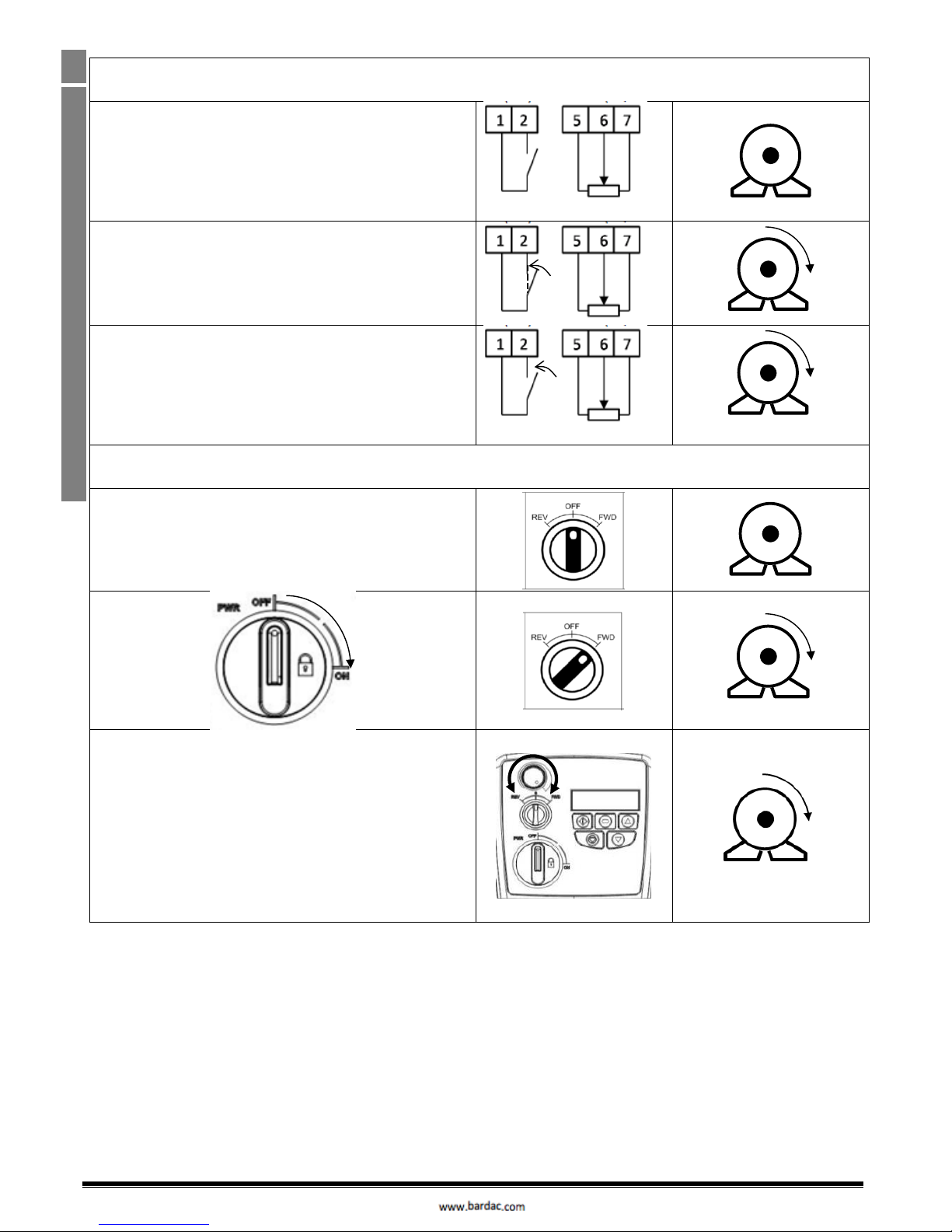
Quick Start – IP20 & IP66 Non Switched
Connect a Start / Stop switch between control terminals 1 & 2
5k – 10k
Close the Switch to Start
Open to Stop
Connect a potentiometer (5k – 10kΩ) between terminals as shown
to vary the speed from P-2 (0Hz default) to P-01 (50 / 60 Hz default)
0....10V
0.......50/60Hz
Quick Start – IP66 Switched
Switch the unit on using the isolator switch on the panel.
The OFF/REV/FWD will enable the output to the motor.
NOTE : With single phase motors, forward rotation only is possible.
The potentiometer will control the speed.
0.......50/60Hz
Optidrive ODE-3 1Ph Output User Guide Revision 1.00
www.invertekdrives.com
7
2
General Information and Ratings
2. General Information and Ratings
This chapter contains information about the Optidrive E3 including how to identify the drive
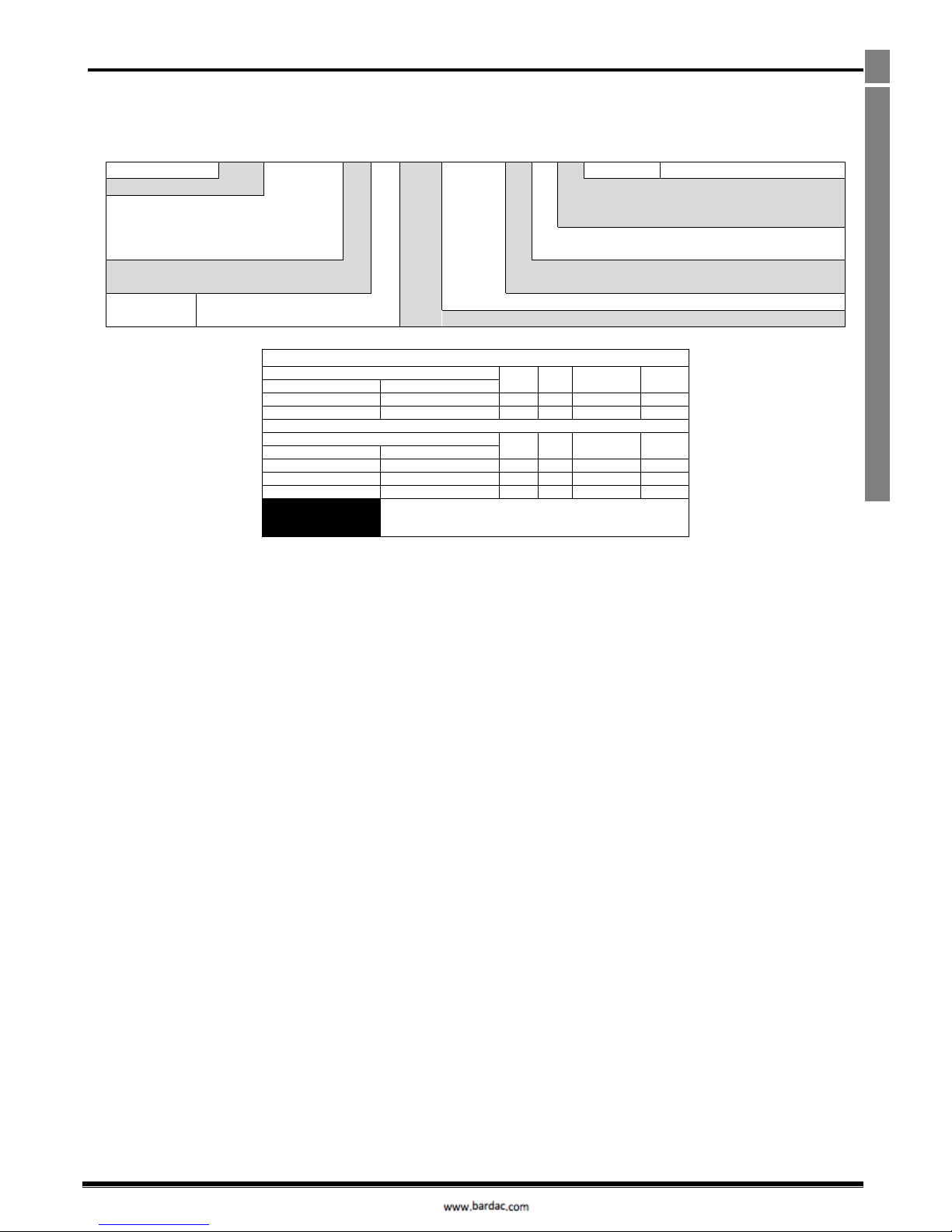
2.1. Identifying the Drive by Model Number
Each drive can be identified by its model number, as shown in the table below. The model number is on the shipping label and the drive
nameplate. The model number includes the drive and any options.
ODE
-
3
-
1
2
0021
-
1
F
1
2
-01
Single Phase Output
Product Family
IP Rating
2 = IP20
X = IP66 Non Switched
Y = IP66 Switched
Generation
Dynamic Brake
Transistor
1 = Not Fitted
4 = Internal Transistor
Frame Size
Filter Type
0 = No Filter
F = Internal EMC Filter
Input Voltage
1 = 110 – 115
2 = 200 – 240
No. Of Input Phases
Output Current x 10
2.2. Drive Model Numbers
110 – 115V + / - 10% - 1Phase Input – 1 Phase 110V Output (Voltage Doubler)
Model Number
kW
HP
Output
Current (A)
Frame
Size
With Filter
Without Filter
N/A
ODE-3-110070-101#-01
0.5
7.0 1 N/A
ODE-3-210105-104#-01
0.75
10.5
2
200 – 240V + / - 10% - 1Phase Input – 1 Phase Output
Model Number
kW
HP
Output
Current (A)
Frame
Size
With Filter
Without Filter
ODE-3-120043-1F1#-01
ODE-3-120043-101#-01
0.37
0.5
4.3
1
ODE-3-120070-1F1#-01
ODE-3-120070-101#-01
0.75 1 7.0
1
ODE-3-120105-1F4#-01
ODE-3-120105-104#-01
1.1
1.5
10.5
2
NOTE
For IP20 units, replace ‘#’ with ‘2’
For IP66 Non Switched Units, replace ‘#’ with ‘X’
For IP66 Switched Units, replace ‘#’ with ‘Y’
Optidrive ODE-3 1Ph Output User Guide Revision 1.00
8
www.invertekdrives.com
3
Mechanical Installation
3. Mechanical Installation
3.1. General
The Optidrive should be mounted in a vertical position only, on a flat, flame resistant, vibration free mounting using the integral mounting
holes or DIN Rail clip.
IP20 Optidrives must be installed in a pollution degree 1 or 2 environment only.
Do not mount flammable material close to the Optidrive
Ensure that the minimum cooling air gaps, as detailed in section 3.5 and 3.7 are left clear
Ensure that the ambient temperature range does not exceed the permissible limits for the Optidrive given in section 9.1
Provide suitable clean, moisture and contaminant free cooling air sufficient to fulfil the cooling requirements of the Optidrive
3.2. UL Compliant Installation
Refer to section 9.3 on page 27 for Additional Information for UL Compliance.
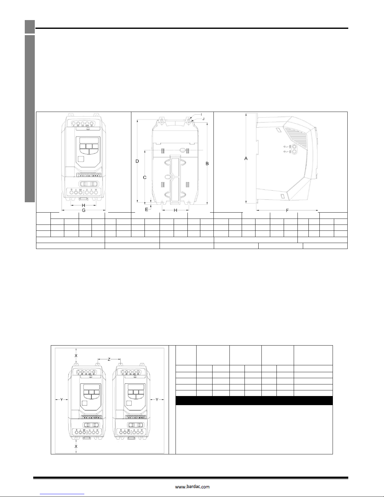
3.3. Mechanical Dimensions and Mounting – IP20 Open Units
Drive
Size
A B C D E F G H I J Weight
mm
in
mm
in
mm
in
mm
in
mm
in
mm
in
mm
in
mm
in
mm
in
mm
in
Kg
lb
1
173
6.81
160
6.30
109
4.29
162
6.38 5 0.20
123
4.84
83
3.27
50
1.97
5.5
0.22
10
0.39
1.0
2.2
2
221
8.70
207
8.15
137
5.39
209
8.23
5.3
0.21
150
5.91
110
4.33
63
2.48
5.5
0.22
10
0.39
1.7
3.8
Mounting Bolts
Frame Size 1 – 2
4 x M5 (#8)
Frame Size 4
4 x M8
Tightening Torques
Frame Sizes 1 – 2
Control Terminals
0.5 Nm (4.5 lb-in)
Power Terminals
1 Nm (9 lb-in)
3.4. Guidelines for Enclosure Mounting – IP20 Units
IP20 drives are suitable for use in pollution degree 1 environments, according to IEC-664-1. For pollution degree 2 or higher environments,
drives should be mounted in a suitable control cabinet with sufficient ingress protection to maintain a pollution degree 1 environment
around the drive.
Enclosures should be made from a thermally conductive material.
Ensure the minimum air gap clearances around the drive as shown below are observed when mounting the drive.
Where ventilated enclosures are used, there should be venting above the drive and below the drive to ensure good air circulation. Air
should be drawn in below the drive and expelled above the drive.
In any environments where the conditions require it, the enclosure must be designed to protect the Optidrive against ingress of airborne
dust, corrosive gases or liquids, conductive contaminants (such as condensation, carbon dust, and metallic particles) and sprays or
splashing water from all directions.
High moisture, salt or chemical content environments should use a suitably sealed (non-vented) enclosure.
The enclosure design and layout should ensure that the adequate ventilation paths and clearances are left to allow air to circulate through the
drive heatsink. Invertek Drives recommend the following minimum sizes for drives mounted in non-ventilated metallic enclosures:-
Drive
Size X Above &
Below
Y
Either
Side
Z
Between
Recommended
airflow
mm
in
mm
in
mm
in
CFM (ft3/min)
1
50
1.97
50
1.97
33
1.30
11
2
75
2.95
50
1.97
46
1.81
22
Note :
Dimension Z assumes that the drives are mounted side-by-side with
no clearance.
Typical drive heat losses are 3% of operating load conditions.
Above are guidelines only and the operating ambient temperature of
the drive MUST be maintained at all times.
Bardac Drives
Optidrive ODE-3 1Ph Output User Guide Revision 1.00
www.invertekdrives.com
9
3
Mechanical Installation
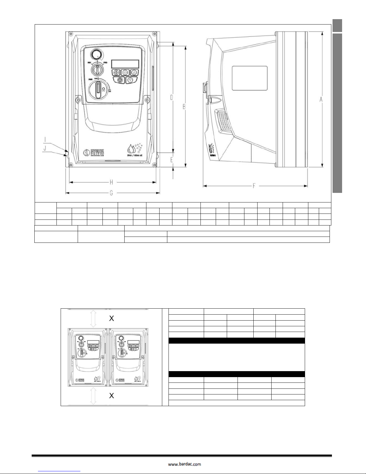
3.5. Mechanical Dimensions – IP66 (Nema 4X) Enclosed Units
Drive Size
A B D E F G H I J
Weight
mm
in
mm
in
mm
in
mm
in
mm
In
mm
in
mm
in
mm
in
mm
in
kg
lb
1
232.0
9.13
207.0
8.15
189.0
7.44
25.0
0.98
179.0
7.05
161.0
6.34
148.5
5.85
4.0
0.16
8.0
0.31
3.1
6.8
2
257.0
10.12
220.0
8.67
200.0
7.87
28.5
1.12
187.0
7.36
188.0
7.40
176.0
6.93
4.2
0.17
8.5
0.33
4.1
9.0
Mounting Bolts
All Frame Sizes
4 x M4 (#8)
Tightening Torques
All Frame Sizes
Control Terminals
0.5 Nm (4.5 lb-in)
Power Terminals
1 Nm (9 lb-in)
3.6. Guidelines for mounting (IP66 Units)
Before mounting the drive, ensure that the chosen location meets the environmental condition requirements for the drive shown in
section 9.1
The drive must be mounted vertically, on a suitable flat surface
The minimum mounting clearances as shown in the table below must be observed
The mounting site and chosen mountings should be sufficient to support the weight of the drives
Using the drive as a template, or the dimensions shown above, mark the locations required for drilling
Suitable cable glands to maintain the ingress protection of the drive are required. Gland holes for power and motor cables are pre-
moulded into the drive enclosure, recommended gland sizes are shown above. Gland holes for control cables may be cut as required.
Drive Size
X Above & Below
Y Either Side
mm
in
mm
in
1
200
7.87
10
0.39
2
200
7.87
10
0.39
Note:
Typical drive heat losses are approximately 3% of operating load
conditions.
Above are guidelines only and the operating ambient temperature of
the drive MUST be maintained at all times.
Cable Gland Sizes
Drive Size
Power Cable
Motor Cable
Control Cables
1
M20 (PG13.5)
M20 (PG13.5)
M20 (PG13.5)
2
M25 (PG21)
M25 (PG21)
M20 (PG13.5)
 Loading...