

User manual
RFID IND-LED, RFID IND-LCD
Soft >= 0.46
User manual RFID IND-LED/LCD Page 1 of 51
[B04]

Dear Customer!
Thank you very much for choosing our product. Before its use, please read these
instructions carefully. Here you find the most appropriate ways of dealing with this
device, the basic principles of safety and maintenance. Please, also keep the user manual
so that you can read it during later use.
Attention!
The manufacturer is not liable for any damage caused by improper use of
the device which differ from its intended purpose, or improper handling, as well
as a fault of driver resulting from improper use.
User manual RFID IND-LED/LCD Page 2 of 51
[B04]

Table of contents
1 PRELIMINARY INFORMATION...................................................................................................................4
2 APPLICATIONS OF THE DEVICE................................................................................................................5
3 WARRANTY AND LIABILITY OF THE MANUFACTURER...................................................................5
4 SAFETY GUIDELINES.....................................................................................................................................6
4.1 POWER SUPPLY...................................................................................................................................................6
4.2 STORAGE, WORK CONDITIONS................................................................................................................................6
4.3 INSTALLATION AND USE OF THE READER.................................................................................................................6
4.4 UTILIZATION OF THE READER................................................................................................................................6
5 CONSTRUCTION OF THE READER............................................................................................................7
5.1 TECHNICAL DATA................................................................................................................................................7
5.2 GENERAL FEATURES............................................................................................................................................9
6 CONFIGURATION OF THE DEVICE.........................................................................................................10
6.1 CHANGING THE DEVICE'S IP ADDRESS BY DISCOVERER APPLICATION.........................................................................10
6.2 CHANGING THE PC'S SUBNET ADDRESS, FOR THE DEVICE CONFIGURATION..................................................................11
7 THE DEVICE FUNCTIONS...........................................................................................................................13
7.1 THE READER STATUS.........................................................................................................................................13
7.2 THE READER WORK MODES.................................................................................................................................14
7.3 CARDS MANAGEMENT........................................................................................................................................16
7.3.1 Add or delete a card using a network browser......................................................................................16
7.3.2 Adding cards by Modbus protocol.........................................................................................................18
7.3.3 User's own API (HTTP GET)................................................................................................................19
7.4 ACCESS GROUPS................................................................................................................................................20
7.5 EVENTS LOG.....................................................................................................................................................22
7.6 READING MIFARE BLOCKS (REFERS ONLY TO MIFARE CLASSIC 1K/4K)....................................................................25
7.7 TEXT MESSAGES..............................................................................................................................................26
7.8 EVENTS RESPONSES – I/O SETTINGS....................................................................................................................27
7.9 REAL TIME CLOCK (RTC)................................................................................................................................30
7.10 SNMP SERVER CONFIGURATION.......................................................................................................................30
7.11 COMMUNICATIONS PROTOCOLS AND ADMINISTRATION............................................................................................31
8 COMMUNICATION WITH THE READER................................................................................................33
8.1 MODBUS.........................................................................................................................................................33
8.2 INTEGRATION WITH USER'S SOFTWARE...................................................................................................................38
8.3 VIEWING THE READER STATUS BY HTTP GET....................................................................................................39
8.4 CONTROL BY HTTP GET PROTOCOL.................................................................................................................40
8.5 EDIT CARDS VIA HTTP POST..........................................................................................................................43
8.6 CONTROLLING BY HTTP PROTOCOL IN CLIENT MODE.............................................................................................45
8.7 COMMUNICATION WITH THE READER FROM AN EXTERNAL NETWORK..........................................................................48
9 CONNECTORS DESCRIPTION....................................................................................................................49
10 DHCP................................................................................................................................................................51
11 RETURN TO THE FACTORY SETTINGS DEFAULT............................................................................51
12 THE READER SOFTWARE UPDATE.......................................................................................................51
User manual RFID IND-LED/LCD Page 3 of 51
[B04]

1 Preliminary information
Before starting work with the device, read The User manual and follow the
instructions contained therein!
Description of visual symbols used in this user manual:
This symbol is responsible for reviewing the appropriate place in the
user instructions, warnings and important information. Failure to
follow warnings could cause injury or damage to the device
Important information and guidelines
Following this guidelines makes the use of the device easier
Attention: The screenshots in this manual can be dissimilar from actual images at
the time of the device purchase. Due to continuous development of the devices
software, some of the functions may differ from these in the manual. The
manufacturer claims no responsibility for any undesirable effects (misunderstanding)
caused by changes of the software.
User manual RFID IND-LED/LCD Page 4 of 51
[B04]

2 Applications of the device
Industry, services, trade, logistics are just some of the industries in which it is possible to
use the reader. It can be used as a machine login tool, room access (storage), loyalty
system component, work time recorder, etc. Using your own application or protocols
supported by the reader the user has the ability to control practically every element of
the reader – display, buzzer, entrances, outputs. Thanks to the built-in memory, it also
has access to the list of logs stored in it. The high-quality IP65 housing provides correct
operation of the reader, even if it is mounted on the facade of the building*.
The "RFID IND-LED/LCD" device is designed to read RFID tags. RFID Standard depends
on module version:
• Mifare Classic® (ISO/IEC 14443-A) RFID IND-LED/LCD Mif
Mifare Plus® (UID), Mifare DESFire® (UID)
• Unique EM4100 EM4102 RFID IND-LED/LCD Uni
• HID iClass® (tylko CSN) RFID IND-LED/LCD iCla
• HID 125kHz RFID IND-LED/LCD H125
• ICODE® (ISO 15693) RFID IND-LED/LCD Ico
• HITAG (HITAG 2) RFID IND-LED/LCD HT2
The device is used for an integration with other systems by way of of modbus RTU/TCP,
HTTP client / server, SNMP protocols. The reader can also work as a standalone device.
* it is necessary to use cable gland
3 Warranty and liability of the manufacturer
The manufacturer provides a 2-year warranty on the device. The manufacturer also
provides post-warranty service for 10 years from the date of the introducing the device
on the market. The warranty covers all defects in material and workmanship.
The manufacturer undertakes to comply with the contract of guarantee, if the following
conditions are met:
all repairs, alterations, extensions and device calibrations are performed by the
manufacturer or authorized service,
supply network installation meets applicable standards in this regard,
the device is operated in accordance with the recommendations outlined in this
manual,
the device is used as intended.
The manufacturer assumes no responsibility for consequences resulting from improper
installation, improper use of the device, not following this manual and the repairs of the
device by individuals without permission.
This device doesn’t contain serviceable parts.
User manual RFID IND-LED/LCD Page 5 of 51
[B04]

4 Safety guidelines
The reader has been designed and built using modern electronic components, according
to the latest trends in the global electronics. In particular, much emphasis was placed on
ensuring optimum safety and reliability of control.
The device has a housing with a high-quality plastic.
4.1 Power supply
The RFID readers require 10-24VDC power supply or optionally POE IEEE 802.3af.
4.2 Storage, work conditions.
The reader is equipped with a sealed IP65 enclosure which means:
total resistance to foreign objects
resistance to water jet directed directly to the device
storage and operation at temperatures from -25 ° C to + 60 ° C,
4.3 Installation and use of the reader
The reader should be used following the guidelines shown in next part of the
user manual.
4.4 Utilization of the reader
When it becomes necessary to liquidate the device (for instance retiring of the device
from service), please contact the manufacturer or its representative, who are obliged to
respond, appropriately, i.e. collecting the reader from the user. You can also ask the
companies involved in utilization and/or liquidation of electrical or computer equipment.
Under no circumstances should you place the device along with other waste material.
User manual RFID IND-LED/LCD Page 6 of 51
[B04]
5 Construction of the reader
5.1 Technical data
Power supply:
DC: 10-24VDC (screw terminals 3,5mm)
or PoE IEEE 802.3af (depends on the version)
or Passive PoE 12-24VDC (depends on the version)
Power consumption: max 2.5W (~200mA@12V)
Transponders:
Tag reading distance: up to 8cm from the directions of the device front side
(display or LEDs)
Wbudowana pamięć: 1000 tagów, 30000 zdarzeń
Internal memory: 1000 tags, 30000 events
Inputs:
number of inputs: 2
input type: opto-isolator, dry contact (NO)
Outputs:
number of outputs: 2
output type: relay NO
maximum relay current load: 1A @ 30VDC
Communication:
1 port Ethernet, 10Mbps
1 port RS485, modbus RTU
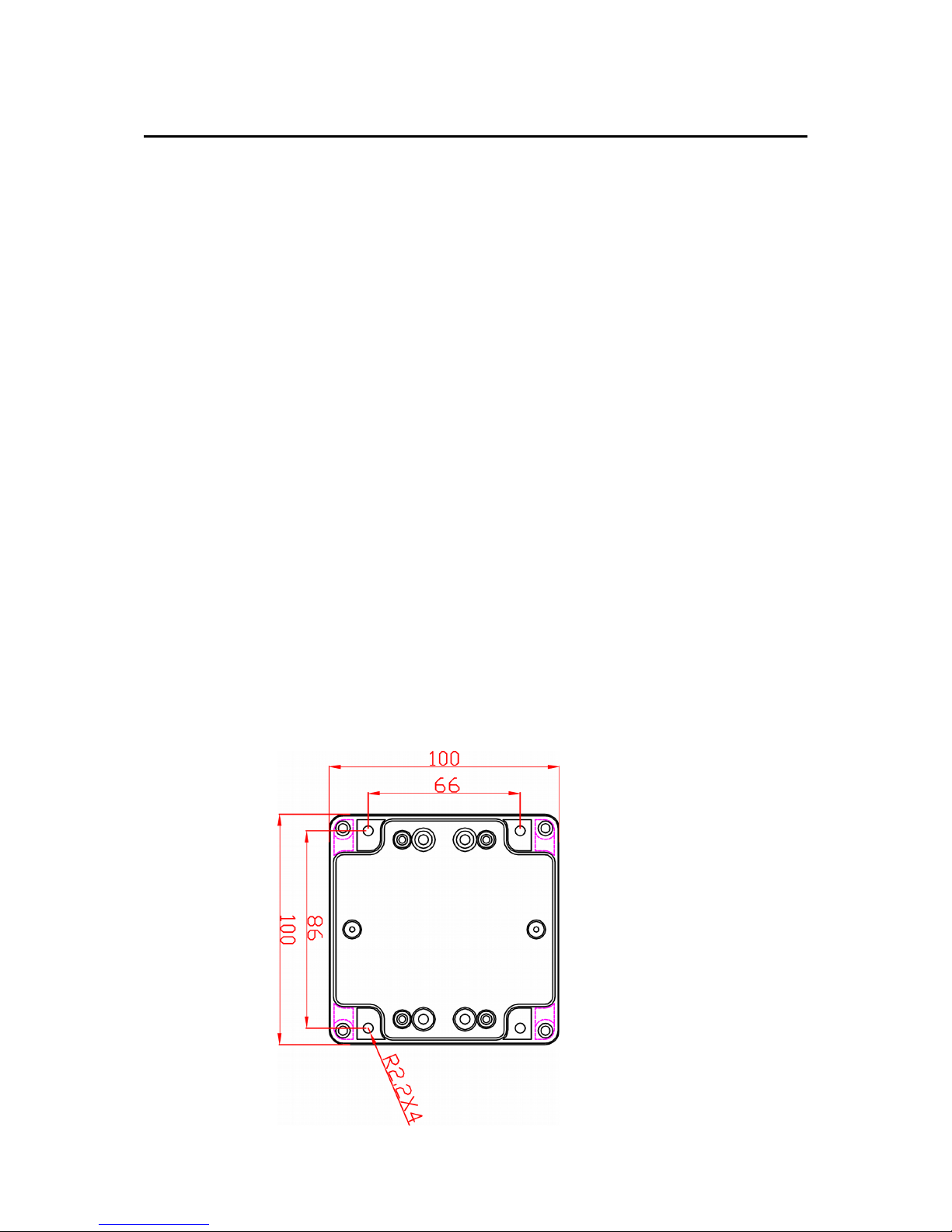
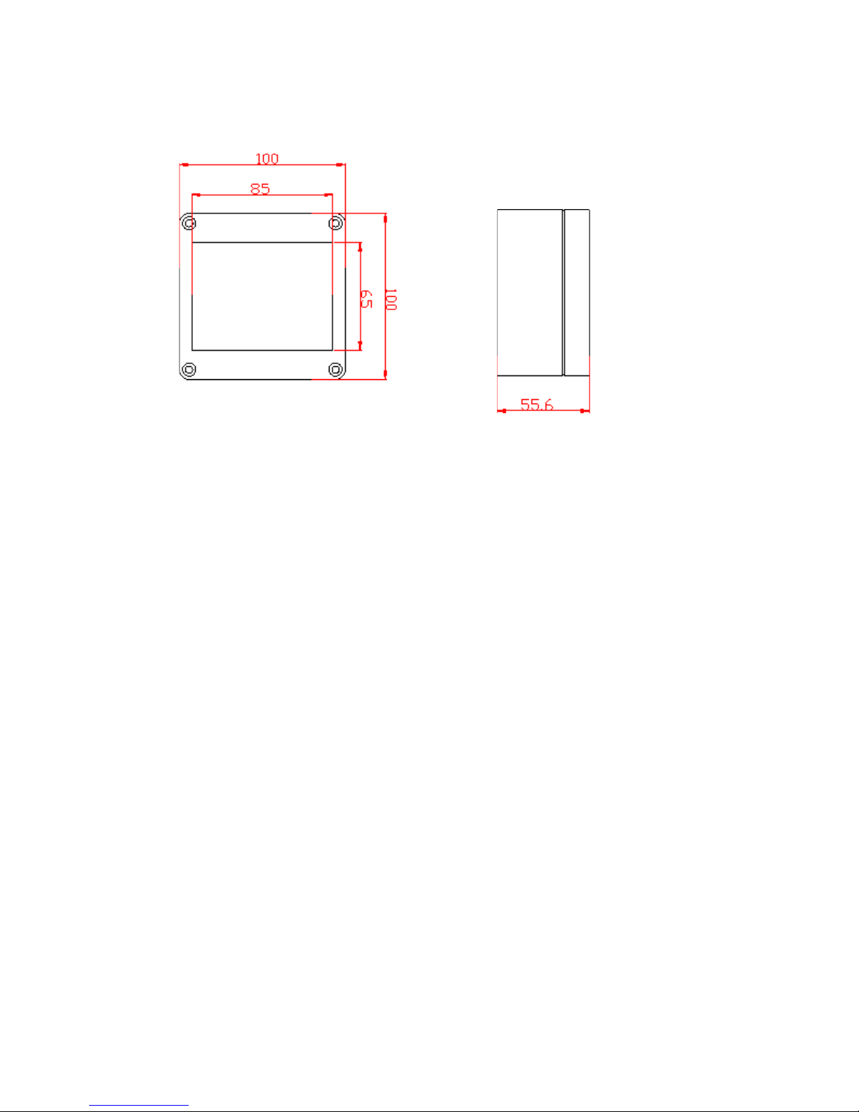
Enclosure:
IP Rating: IP65
Dimensions:
User manual RFID IND-LED/LCD Page 7 of 51
[B04]
User manual RFID IND-LED/LCD Page 8 of 51
[B04]
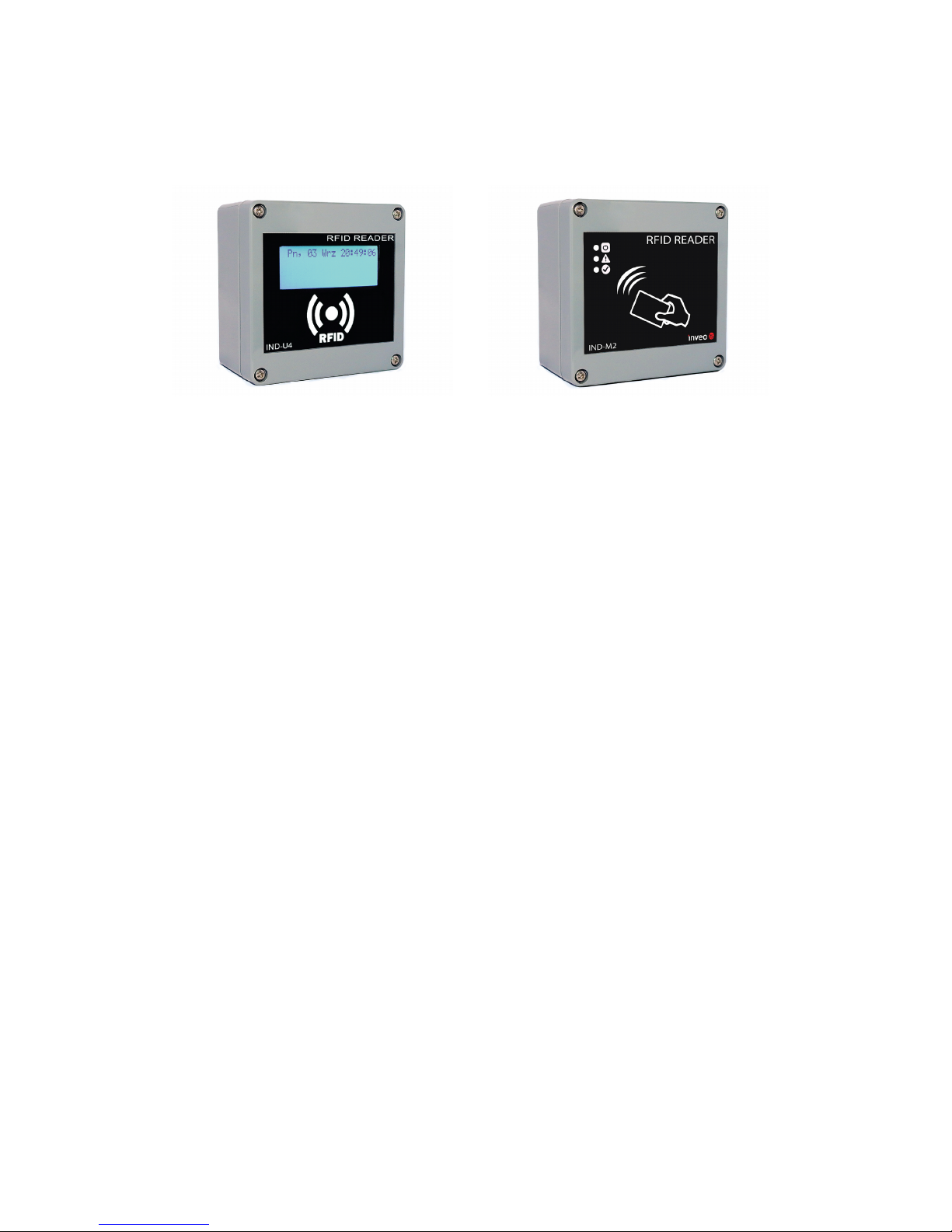
5.2 General features
General view of the RFID IND-LCD and RFID IND-LED is shown below.
Communication with the reader is carried out by the LAN or RS485.
User can choose from the following options to access the code readout from a RFID tag:
– through built-in web server, using a standard web browser (preferred browsers
are MOZILLA FIREFOX, OPERA, CHROME),
– HTTP server mode
– HTTP client mode
– MODBUS TCP
– MODBUS RTU (RS485)
– SNMP
The reader, depending on the version, is equipped with an LCD display or LED diodes for
power supply indication and current state of the device.
User manual RFID IND-LED/LCD Page 9 of 51
[B04]
General view of the
RFID IND-LCD
General view of the
RFID IND-LED
6 Configuration of the device
The device when used for first time needs to be configured.
There are two methods to do so. The network configuration can be easily changed by
Inveo “Discoverer” (https://inveo.com.pl/software/) software:
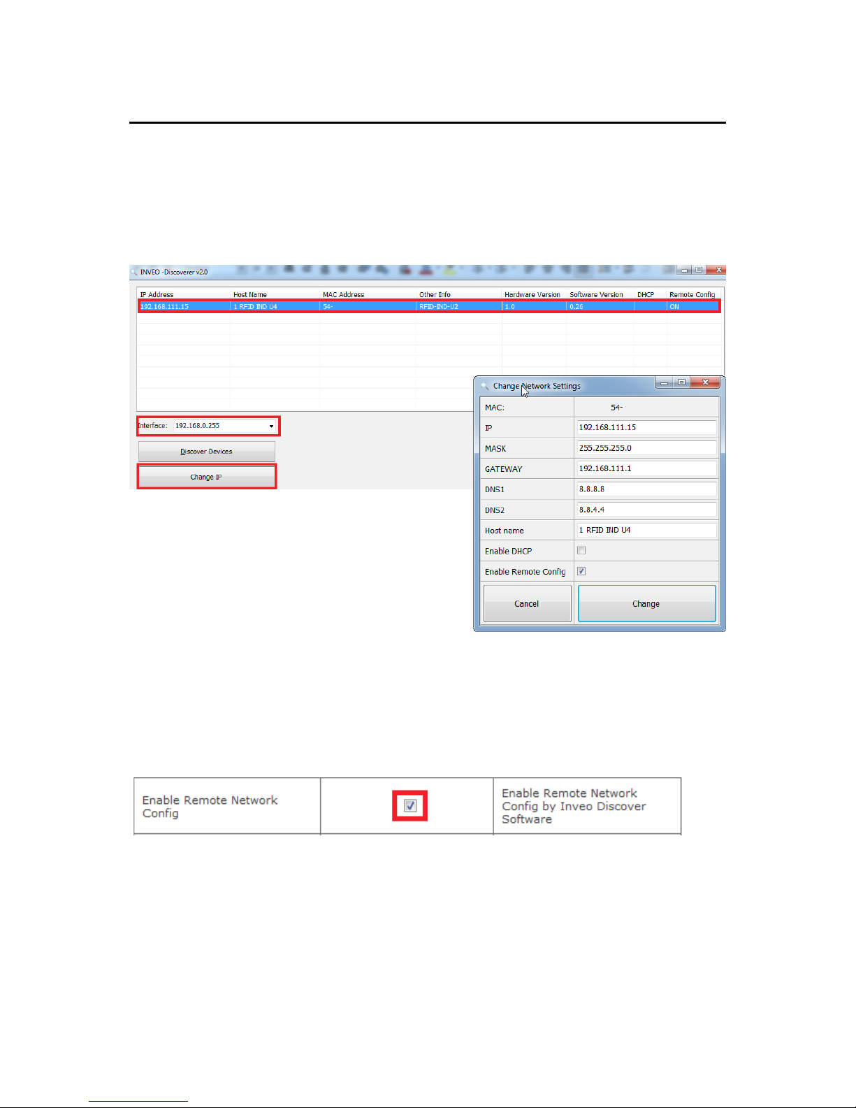
6.1 Changing the device's IP address by Discoverer application.
When the “Discoverer” is opened and the relevant device is found, choose Interface list
box and click on Change IP button.
In a new opened dialog box, settings such
as IP address, MASK, GATEWAY, DNS1/DNS2
and the Host name can be changed.
Please save correct settings by choosing
Change button.
If Remote Config is disabled (enabled by default), it is necessary to configure
the device by changing the computer's subnet (chapter 6.2).
To enable the remote configuration it is necessary to enter tabs Administration
and check mark Enable Remote Network Config.
Save the setup by selecting Save Config button.
User manual RFID IND-LED/LCD Page 10 of 51
[B04]
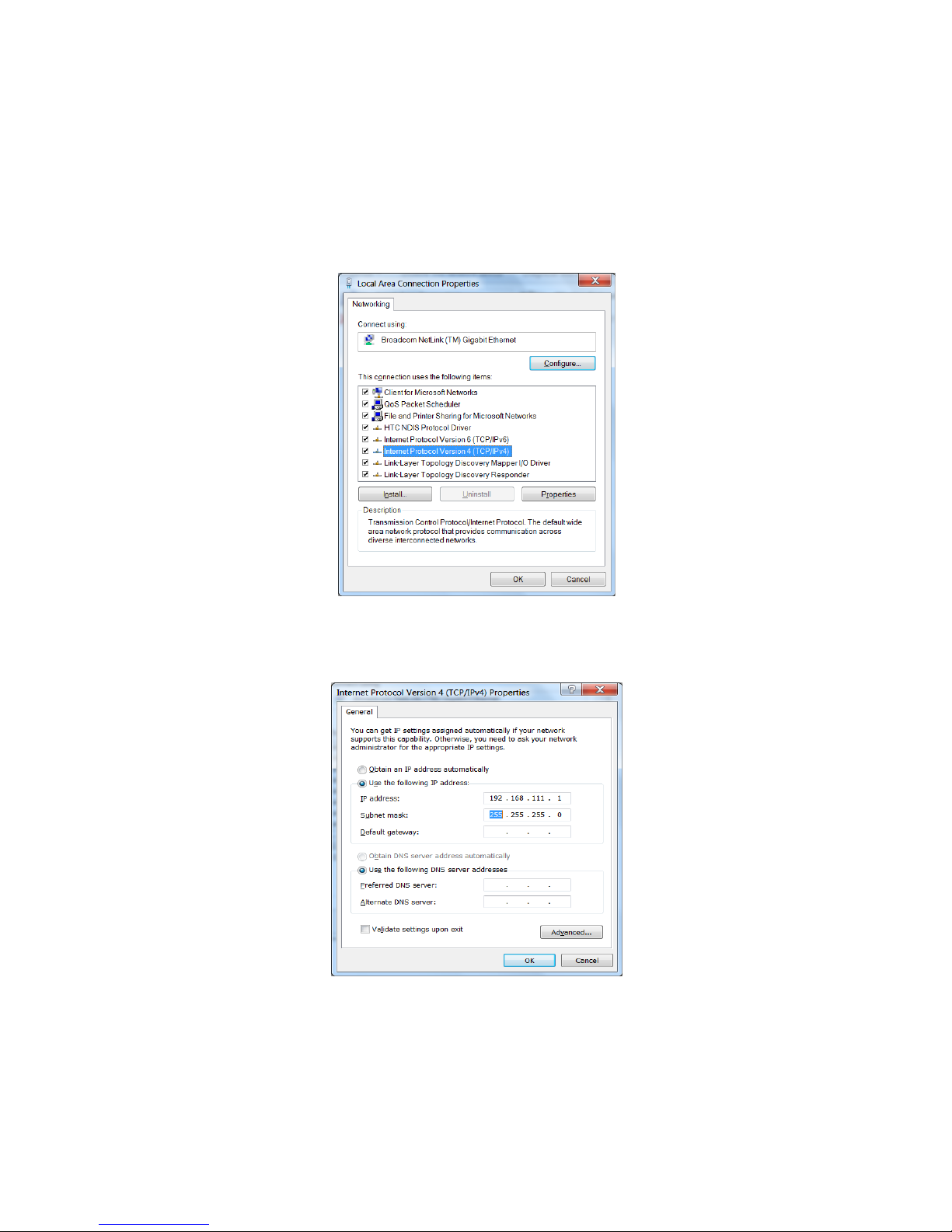
6.2 Changing the PC's subnet address, for the device configuration
After the device is connected to a network, a subnet address of a PC which is connected
to the same network has to be changed.
To do so, go to the PC's MS Windows network configuration: Start->Control panel
->Network and Sharing Center->Network and Internet->Network Connections, choose
the related controller and right click on „Properties”.
After selecting this option configuration window will show up:
Next choose "Internet Protocol (TCP/IP)", double click on it and enter following settings:
After saving changes by clicking OK, open an Internet browser and enter in the browser's
address line: 192.168.111.15.
Default user name/password: admin/admin00
User manual RFID IND-LED/LCD Page 11 of 51
[B04]
Changing network settings in MS WINDOWS
Illustrative TCP/IP protocol settings
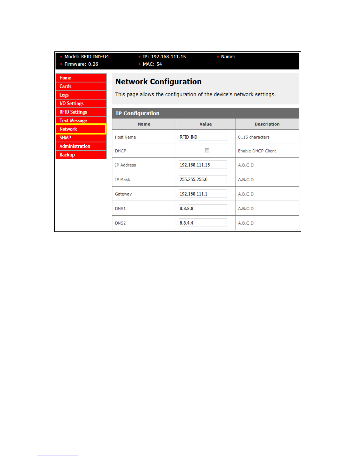
Next select option „NETWORK”
To change the network settings of the reader, use the following fields:
Host Name – NETBIOS name,
DHCP – checking this box forces use of the address assigned by the DHCP server
IP Address – the IP address of the reader (at this address, the reader will be visible on
the network),
IP Mask – IP subnet mask,
Gateway – network gateway,
DNS1 – DNS servers addresses,
DNS2 – DNS servers addresses,
After making changes, select Save.
User manual RFID IND-LED/LCD Page 12 of 51
[B04]
Configuration of the network connection
7 The device functions
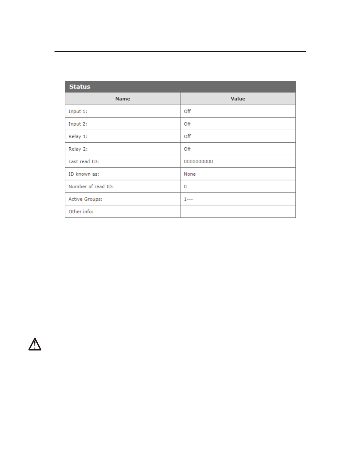
7.1 The reader status
The reader status can be found at Home tab in the reader's menu (192.168.111.15).
Selected HOME tab shows following information:
Status Table:
Input 1 – input number 1 current status (binary input),
Input 2 – input number 2 current status (binary input),
Relay 1 – current status of relay output number 1,
Relay 2 – current status of relay output number 2,
Last read ID – last tag readout in HEX format,
ID known as – type of tag read (unknown/user),
Number of read IDs – number of read IDs since the reader's reset,
Active Groups – numbers of groups that are active at this moment,
Other info – this can inform about the reader-server protocol communication timeout
(message: Protocol Timeout!).
Attention:
If readout at a last read ID shows 8500c2b4a8 (LOCK!) it indicates blocking of further
tags reading until releaseId (HTTP GET) command is sent or in case of Modbus,
value “0” has to be sent to 1 Holding Reg address or 1004 Single Coil address.
User manual RFID IND-LED/LCD Page 13 of 51
[B04]
7.2 The reader work modes
The device can be set up for various work modes. Enhanced settings allow the reader to
work as a standalone device (Autonomic mode) as well as it can be controlled by a
software.
Standalone – Autonomic mode
In this mode the reader isn't connected to network and compares tag readout with its
own internal memory, opens a lock's bolt by drawing a RFID card near to the reader, and
the like.
Controlled by software mode
The reader can be controlled by communications protocols. Time duration of the readerserver communication loss can be set (Timeout value). After expiration of set time, the
device will switch to the autonomic mode.
Remember, when connection with the server is re-established the reader will return to a
software mode control.
User manual RFID IND-LED/LCD Page 14 of 51
[B04]
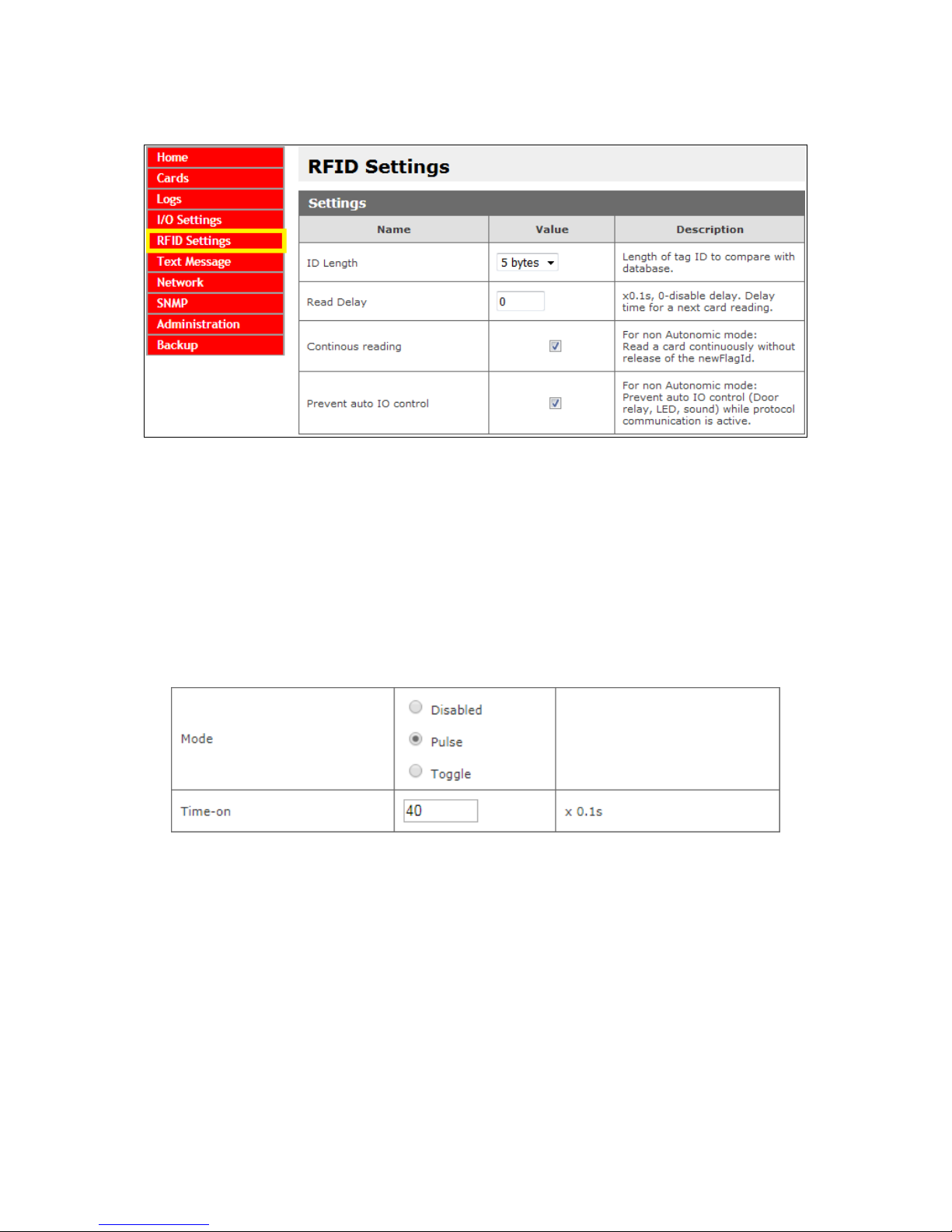
Advanced work settings
ID Length – length of ID code for comparison with cards database
Read Delay – value of read delay for a consecutive tag multiplied by 0.1s
(150 = 15 seconds)
These settings relate to control by communications protocols only:
Continuous reading – "hotel mode" – when this mode is chosen, a card is seen at the
time when it is drawn near to the reader only. If the card is moved away from the
reader, ID code is overwritten by zeros.
Additionally, in I/O Settings tab, table Output Relay 1, the Pulse mode can be set. This
mode allows the reader to hold on to "on" status for set time length after a card is drawn
away. (for example: Time-on = 40 * 0.1s = 4 seconds).
Often this mode is used to maintain power supply for a machinery which is active only
when an authorized employee logs in using a card reader. Likewise, it is used in hotel
systems. Hotel rooms are often powered after a card is seen by a reader *special
purpose housing.
Prevent auto IO control – enforces software control of outputs, LED diodes and
display, when the reader is controlled by a communications protocol. This mode is useful
together with the reader-server communication loss time expiration setting, as the
reader will switch to autonomic mode after set up time expire. In turn, during control by
software, server/controller ought to maintain interaction with the reader. If server lost
connection and the device start standalone mode, the reader will respond as it is set in
"I/O Settings" tab.
User manual RFID IND-LED/LCD Page 15 of 51
[B04]
7.3 Cards management
The reader supports card management through implemented communication protocols as
well as using external software.
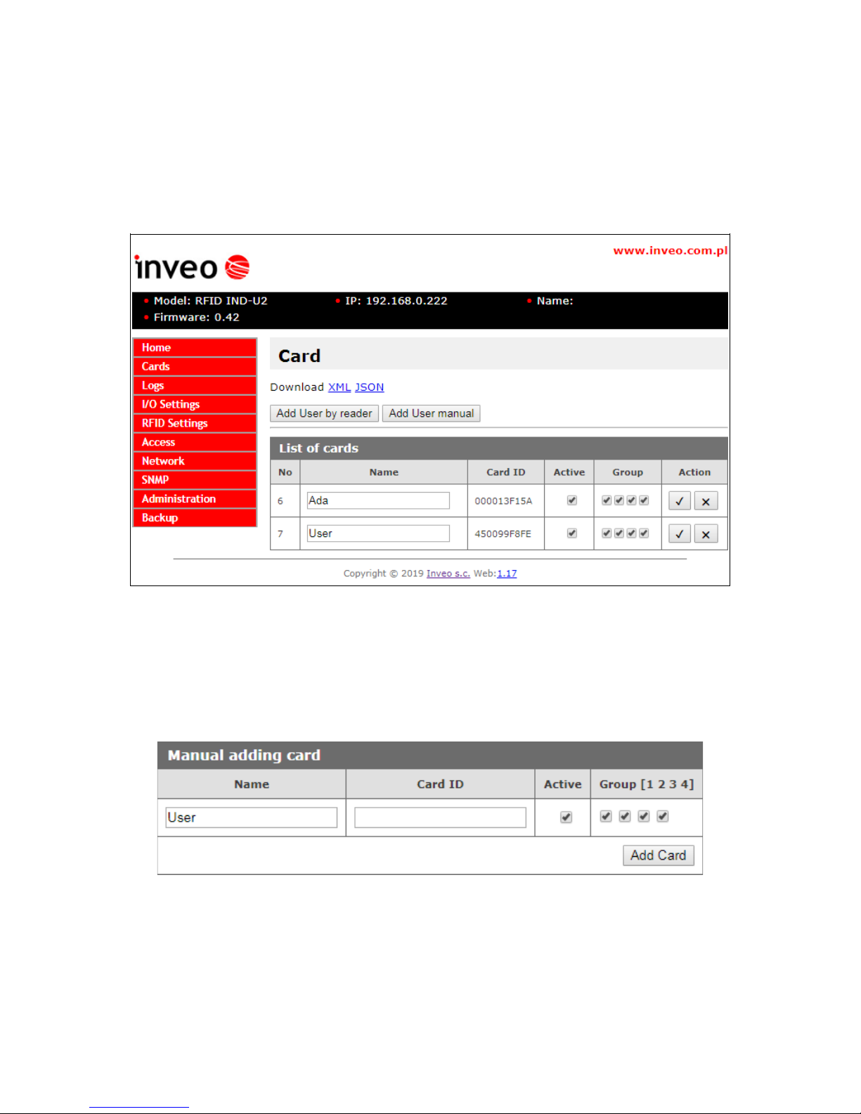
7.3.1 Add or delete a card using a network browser
At the browser, in the reader's Cards tab, a user can assign TAGs that the reader will
recognize.
To add a new user card, on the Cards tab, click the Add User by reader button, and
then approximate the card to the reader. The assignment of the card will be signalized by
the appropriate beep.
If the user does not have a physical TAG, and there is a need to add a new user, press
the button Add User manual. The following window will be displayed:
In the window above, just give the user name, enter the ID of the card and assign to the
appropriate groups. The entered data confirm the Add Card button.
After correct assignment, in the List of cards table a new record will show up.
User manual RFID IND-LED/LCD Page 16 of 51
[B04]

The List of cards table allows you to edit cards stored in the module's memory.
Active field activates or deactivates the selected card, so that the user blocked after
applying the card will not be recognized.
The Group option is responsible for activating the card at a specified time (chapter 7.4).
The button sis responsible for saving the current settings.
The button sallows to remove the card from the reader's memory.
All cards in the reader memory can be retrieved by referencing to the resource file
cardList.xml (e.g. http://192.168.111.15/cardList.xml).
Sample:
<cardList>
<cardItem>
<no>5</no>
<name>Ada</name>
<active>1</active>
<group>1001</group>
<cardId>000013F15A</cardId>
</cardItem>
<cardItem>
<no>6</no>
<name>User</name>
<active>1</active>
<group>0111</group>
<cardId>450099F8FE</cardId>
</cardItem>
</cardList>
Cards can be added as well by a computer application “RfidIndManager”
available from www.inveo.com.pl
To add cards to the reader's memory choose CSV file with a recorded card number, a
user name and a card ID. RfidIndManager application will connect with the reader and
will write the cards to the reader's memory.
User manual RFID IND-LED/LCD Page 17 of 51
[B04]

7.3.2 Adding cards by Modbus protocol
The reader features build Modbus protocol ability. Using the protocol a customer may
write a new card and the card user name to the reader's memory.
In chapter 8.1, in a table, all Modbus addresses for the RFID readers can be found.
In a following example, values sent to Holding Registers are decimal.
The example of a Mifare card recording:
card number 8
card id: 4923267D
user name: John
At the beginning Modbus RTU or TCP function has to be enabled.
Modbus communication with a PC can be established by attaching USB – RS485
converter cable or by TCP connection. In the next step open up an application for
working with Modbus and select the PC as the master. At this time it is worth to set up
number of Holding Registers items from 1100 to 1150 address (50 items), so possible
errors can be corrected.
After the configuration set up, open the addresses edition window.
To write a card number the required value reduced by 1 has to be sent to 1100 address
of Holding Registers (e.g. for a number “8” a value “7” has to be sent).
In the next step the card has to be configured by sending proper value to 1101 address.
(see chapter 8.1)
Later, the card's ID bytes has to be segmented and changed to decimal values.
49 (hex)=73 (dec)
23 (hex)=35 (dec)
26 (hex)=38 (dec)
7D (hex)=125 (dec)
4 bytes for Mifare cards, 5 bytes for UNIQUE cards
Writing the card ID take place by sending the segments of bytes to 1102-1105 Holding
Registers addresses.
Lastly, the user name has to be written by changing actual name to ASCII code.
J=74
o=111
h=104
n=110
The user name in ASCII code values has to be sent to Holding Registers starting from
1110 address (in the example: 1110-1113). The name has to be finalized with NULL, so
at the last ASCII code “0” has to be written to a subsequent address
(in the example: 1114).
The screen shot shows the Holding Registers addresses and corresponding values as in
the example.
User manual RFID IND-LED/LCD Page 18 of 51
[B04]

7.3.3 User's own API (HTTP GET)
Other method of a card registering in the reader's memory is applying commands of the
httpGET protocol.
To add a new card enter in an address field of the browser:
„thereaderIPaddress”/msg.php?addId=”thecardID” in hexadecimal numeral system
„thereaderIPaddress”/msg.php?addDecId=”thecardID” in decimal numeral system
e.g. http://192.168.111.15/msg.php?addId=0600ADDA62
The reader returns number at which the new card is recorded:
Using this number the card's user name can be added by writing:
„thereaderIPaddress”/msg.php?changeName=”the card number”!”user name”
e.g. http://192.168.111.15/msg.php?changeName=8!John
Cards can be added, by sending command: „theDeviceIPaddress”/msg.php?addCard.
First read the card then write the above command to the browser. The reader writes in
the last read tag. After the command execution the reader returns a number of the card.
Next, to add a user name enter as before a command:
„thereaderIPaddress”/msg.php?changeName=”the card number”!”user name”
More about HTTP GET commands in a chapter 8.4.
User manual RFID IND-LED/LCD Page 19 of 51
[B04]

7.4 Access groups
The reader allows you to activate selected cards at a specified time. This means that you
should set the time from which the user will be recognized in the system. Group
configurations are made in the Access tab.
In the Access Groups table, you can set 4 activation times for the group. The individual
fields of the table mean:
• enable rule – rule activation,
• start time – group activation time (at 21:00, groups 1 and 2 are inactive, and
groups 3 and 4 are active),
• group 1-4 – assigning the rule to the groups.
The configuration of each rule should be saved with the Save button.
Attention! If the Enable rule field is not checked, the group assignment for this rule
will not unlock the card.
Attention! In the case when several groups with different activation rules are assigned
to the card, the rule that activates the card takes priority.
Attention! If the card is not assigned to any group, it means its deactivation.
Example No. 1:
Only rules No. 1 and 2 are enabled.
Card with group 1 will be active all day.
Cards with groups 2, 3 and 4 will be active from 14:00 to 7:00.
User manual RFID IND-LED/LCD Page 20 of 51
[B04]

Example No. 2:
Rules No. 1 and 3 and 4 are enabled.
Groups:
Before 7:00 am, group 4 is active (rule from 21:00). At 7:00 the group 4 is deleted and
group 1 is activated. At 14:00, rule number 2 begins, which should delete rule 1.
The Enable rule field is not checked, so the reader does not include this rule.
At 15:00, group 1 is deactivated but groups 3 and 4 are activated. From 21:00 to 7:00
only group 4 is active. Group 2 is inactive all day.
Users:
Groups 2 and 3 are assigned to the user Olaf. The user will be recognized in the system
between 15:00 and 21:00. Only rule No. 3 activates group 3.
Groups 1 and 4 are assigned to the user John. This means that the card will be active
all day. From 7:00 the group 1 is activated. At 15:00, Group No. 1 is inactive, however
group 4 is activated. Group 4 is deactivated at 7:00.
Groups 1, 2 and 3 are assigned to the user Rex. This user's card will be active from
7:00 to 21:00. From 7:00 the group 1 is activated. At 15:00 the rule for group No. 1 is
deleted, but the rule for group 3 is fulfilled. At 21:00 the rule for group 3 is deleted.
User manual RFID IND-LED/LCD Page 21 of 51
[B04]

7.5 Events log
The reader has ability to log tags readout data.
To record a log of a RFID tag readout in the reader's memory, in the menu select RFID
Settings Logger → and enable Log mode.
Events logs can be viewed by:
1. WWW page (The menu Logs tab)
2. XML file
3. Modbus – readout from relevant addresses (chapter 8.1)
4. raw file
Events logger setup panel
Log mode: Disabled – logging disabled
Log mode: Enabled – logging to internal memory enabled
Log a card removal – selecting this option results in an additional record of an event
when a tag has been drawn away, after it was drawn near the reader for more then 5
seconds. The option is available in the “Continuous reading” mode, only.
Log when controlled by a protocol – this option allows to log events even the reader
is controlled by a network protocol. By default the reader, when operated by a network
protocol doesn't log events.
User manual RFID IND-LED/LCD Page 22 of 51
[B04]

1. Reading events logs at the WWW site.
Log table with cards readout.
Marked in the log table, cards ID data is an example of unrecognized cards which are not
registered in the reader's memory or the card is inactive.
Remove logs deletes all logs from the reader's memory.
There is a real time clock inbuilt into the reader. After selecting Update time button the
internal reader's clock will synchronize with the connected computer current time.
User manual RFID IND-LED/LCD Page 23 of 51
[B04]

2. Preview of events by XML file
All cards logs in the reader memory can be retrieved by referencing to the resource file
theDeviceIPaddress/logList.xml or on the Logs tab press Download XML line.
Sample:
<logList>
<logItem>
<no>1</no>
<id>0</id>
<name/>
<cardId>450099F8FE</cardId>
<state>00000110</state>
<time>1554297226</time>
</logItem>
<logItem>
<no>2</no>
<id>7</id>
<name>John</name>
<cardId>450099F8FE</cardId>
<state>10000110</state>
<time>1554297249</time>
</logItem>
<logItem>
<no>3</no>
<id>0</id>
<name/>
<cardId>04001BB7BC</cardId>
<state>00000110</state>
<time>1554297259</time>
</logItem>
</logList>
- no – log number
- id – ID number of the defined card from the Cards tab,
- name – name of recognized card. For unsaved or inactive cards this tag is empty,
- cardID – the UID number of the card,
- state – it refer only to the RCP reader with keys – flag defines which function keys have
been selected:
Bit
Decimal
value
Description
0 1 Function key no.1 (np. privete)
1 2 Function key no.2 (np. official)
2 4 Function key no.3 (np. entrance)
3 8 Function key no.4 (np. exit)
4 16 Reserved
5 32 Reserved
6 64 Reserved
7 128 The card recognized by the reader
- time – time in Unix format
User manual RFID IND-LED/LCD Page 24 of 51
[B04]

7.6 Reading Mifare blocks (refers only to Mifare Classic 1k/4k)
The reader is able to read Mifare Classic 1k/4k card memory blocks.
It is possible to read one of memory blocks at will. Readout data can be accessed by
HTTPClient or Modbus protocols.
In HTTPClient protocol mode after GET request, next field is a “block” readout in
hexadecimal value (16 Bytes).
Additionally, the block's readout data can be copied as card UID. In this case 4 bytes
from the block started by “Offset for UID” are copied as UID card.
At RFID Settings tab in Mifare Block Reader table there are settings by which reading of
Mifare card blocks can be configured.
Entering an incorrect authentication key results in absence of the reader's sound
indicator output. This condition is considered as a card not having been read.
Enable – a read block function is enabled
Block address – a block address
Auth key – authentication key in hexadecimal value written to read only memory. It is
changed only if necessary. Default key is 6xff (FFFFFFFFFFFF).
Auth key B – Key B choice. By default the authentication key is “A”, in case key “B” is
required mark this option.
Override UID – a card's UID is overwritten with readout data
Offset for UID – an offset for a UID rewrite
Add data to HTTPClient – a block of readout data is added to GET request in HTTP
Client mode
User manual RFID IND-LED/LCD Page 25 of 51
[B04]

7.7 Text Messages
In the Text Message menu, an administrator needs to set up text messages which will
be shown on the reader display during the device's operation e.g. an active card readout,
an inactive card readout, a timeout value.
In the Time table, a local language can be selected for a display of real time in the first
line of the reader's LCD.
User manual RFID IND-LED/LCD Page 26 of 51
[B04]

7.8 Events responses – I/O Settings
The reader has ability to control automatically a sound indicator system, an optical
indicator system and e.g. lock's bolt relay.
Attention! If the reader is set up to control by software mode (chapter 7.2),
configuration of additional functions for control of outputs, as well as for the sound and
optical indicators is needed.
In Input 1 table, when Door unlock option is marked, activation of Input 1 will
automatically switch on the output relay (e.g. for a lock's bolt).
To set the Input 2 configuration, go to the Input 2 table.
Checking the "Open Timeout Alarm" forces the relay No. 2 at the time when the input
No. 2 will be switched on for longer than the time specified in the Max Time field.
With this function, you can connect the door open sensor to the No. 2 input, and the
alarm siren to the No. 2 output will cause that if someone opens the door and does not
close in the specified time, the siren will sound.
All changes must be saved by clicking the Save button.
User manual RFID IND-LED/LCD Page 27 of 51
[B04]

The relay outputs can be configured in the Output Relay 1, Output Relay 2 table.
In Output Relay table a work mode of the relay for a lock's bolt can be adjusted.
No Name Description
1 Mode Disabled – relay control is switched off
Pulse – output activation switches relay on for a set time duration
(e.g. for a lock's control)
Toggle – every tag read event changes the relay state to opposite
2 Time-on The set time duration for activation of the relay in Pulse mode, in
numbers multiplied by 0.1 second (e.g. value 20 equals to 2 seconds)
3 Action Actions modes which activate output.
None (control by a protocol) – control take place by HTTP, SMNP,
MODBUS protocols.
All Cards – activation of output by RFID tags readout of all cards.
Known Cards – activation of output by RFID tags readout of known
cards only.
Unknown Cards – activating the output only after readout
an inactive or unknown tag (for example: warning).
4 Invert
output
It changes the type of relay output from the NO output to the NC
output.
The relay outputs are configured independently.
User manual RFID IND-LED/LCD Page 28 of 51
[B04]

There are three possible sound indicators:
• Accept sound – two audio tones, one after another: first short low and second
longer and higher in tone. “Accepting” sound.
• Reject sound – two audio tones, one after another: first short low, same as for
accept sound and second longer and lower then the first. “Rejecting” sound.
• Short beep – short and low as the first one for accept/reject
In Events table the reader's behavior can be programmed for RFID tags readout events:
No Name Description
1 Sound
Action
Sound indicators for different events modes
None – no sound indicator
All Cards (Accept tone) – the reader makes an accept tone sound
for all cards.
All Cards (Short beep) – the reader makes a short beep tone sound
for all RFID tags.*
Known Cards – the reader makes an accept tone sound for known
cards (recorded in the reader's memory) and reject sound for
unknown.
2 LED/LCD
backlight
Action
The reader's LED, LCD optical indications modes
None – the reader is controlled by HTTP, SMNP, MODBUS protocols.
All Cards – optical indications for all RFID tags
Known Cards – optical indications for known card tags (recorded in
the reader's memory)
* the short beep tone can be used for the reader's communication with a network server.
In this case the reader gives the short beep tone indication for a tag readout, but the
server ought to process received information.
The readers LCD screen backlight has a timeout setting.
When the value is set to 255 the display is always on.
The value set to 0 turns the display off.
The value set to e.g. 5 causes the display to turn on for 5 seconds after a tag's readout.
User manual RFID IND-LED/LCD Page 29 of 51
[B04]

7.9 Real Time Clock (RTC)
The readers are equipped with a real time clock.
The time can be set manually in the Logs tab. The time is copied from the system.
Additionally, a time server can be synchronized with internal time of the reader by SNTP
protocol. The configuration settings is available in NETWORK SNTP tab. →
To switch on synchronization with SNTP server, write its address in Server address field.
If 0.0.0.0 address is entered, time synchronization is switched off.
7.10 SNMP server configuration
The reader is fitted with a SNMP v2c server. This function can be enabled by
Administration Services Enable SNMP→ → .
SNMP protocol facilitates inputs retrieving, setting up outputs status and retrieving ID
number of the read tag.
MIB file which describes the structure is available for download in the SNMP tab under
Download MIB file name.
User manual RFID IND-LED/LCD Page 30 of 51
[B04]

7.11 Communications protocols and administration.
Menu Administration allows for configuration of services, which needs to be active during
operation of the device and for change of an access password.
The reader's name
Every reader may be named for identification purpose.
Change of an access password
In order to change of the password, the current password is written in the value field,
then in New Password and Re-type Password a new password can be entered and
saved with Save Config button.
User manual RFID IND-LED/LCD Page 31 of 51
[B04]

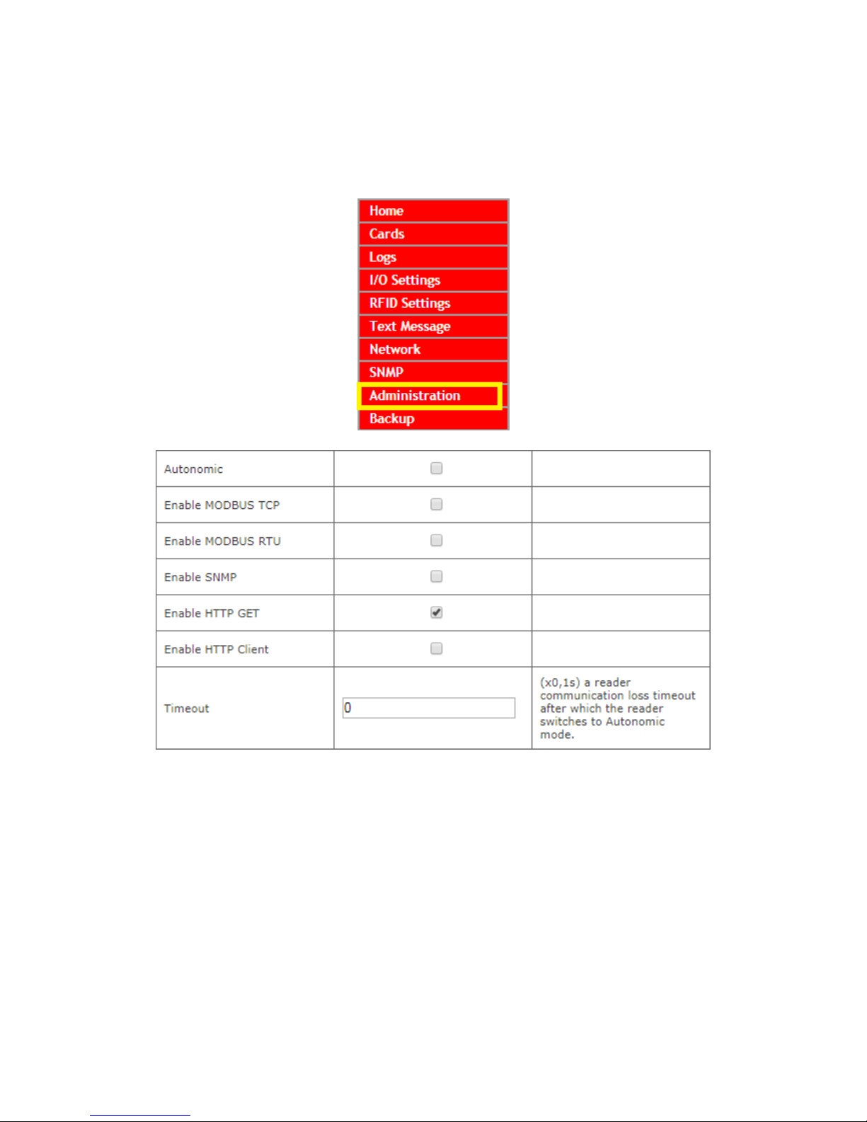
Services setup
The device allows choice of services available for its operation. Services can be activated
by selecting suitable check box.
Autonomic – the reader's standalone mode,
Enable MODBUS TCP– MODBUS TCP service is enabled,
Enable MODBUS RTU– MODBUS RTU service is enabled,
Enable SNMP- SNMP protocol is enabled,
Enable HTTP GET – the reader's HTTP Server work's mode is selected,
Enable HTTP Client – the reader's HTTP Client work's mode is selected,
Timeout – time duration of server-reader communication loss after which the reader
switches to Autonomic mode,
Enable Remote Network Config – remote network configuration is selected (for
Discoverer application),
Enable TFTP Bootloader – TFTP bootloader is enabled.
Attention:
For precaution reason, TFTP Bootloader and Remote Network configuration during
regular operation of the reader, should be disabled. These are enabled for the device
firmware upgrade task, only.
User manual RFID IND-LED/LCD Page 32 of 51
[B04]

8 Communication with the reader
8.1 Modbus
Modbus is available by RS485 (Modbus RTU) or by TCP (Modbus TCP).
Parameters of RS485 port for MODBUS RTU communication can be set at the table:
No Name Description
1 PDU The reader's Modbus address value.
2 Baudrate Data transfer speed
Available speeds: 1200, 2400, 4800, 9600, 19200, 34800, 57600,
115200
3 Parity Parity setting.
Available options:
None, None and 2 Stop, Even, Odd, Mark, Space
After setting the required parameters, enable the Modbus RTU service and confirm with
the Save button.
The reader supports following functions of MODBUS RTU:
- 0x01 Read Coils
- 0x03 Read Holding Register
- 0x05 Write Single Coil
- 0x06 Write Single Register
- 0x0F Write Multiple Coils
- 0x10 Write Multiple Registers
User manual RFID IND-LED/LCD Page 33 of 51
[B04]

No Address Type R/W Description
1 1 Holding Reg R/W Readout flag
Read: 1 – a new transponder has been read
Write: 0 – setting to zero of a readout flag
2 2 Holding Reg R ID_LEN
3 3 Holding Reg R Card ID/UID/CSN [0]
4 4 Holding Reg R Card ID/UID/CSN [1]
5 5 Holding Reg R Card ID/UID/CSN [2]
6 6 Holding Reg R Card ID/UID/CSN [3]
7 7 Holding Reg R Card ID/UID/CSN [4]
8 8 Holding Reg R Card ID/UID/CSN [5]
9 9 Holding Reg R Card ID/UID/CSN [6]
10 10 Holding Reg R Card ID/UID/CSN [7]
11 11 Holding Reg R Card ID/UID/CSN [8]
12 12 Holding Reg R Card ID/UID/CSN [9]
13 13 Holding Reg R Tag's type
14 14 Holding Reg R ID_MODEL
15 15 Holding Reg R ID_SW
16 16 Holding Reg R ID_HW
17 17 Holding Reg R Type of tag read
0 – none TAG
1 – unknown TAG
2 – USER
3 – MASTER
18 100 Holding Reg R For RFID IND M2/M4 only – Mifare block readout
16 subsequent bytes
19 1000 Holding Reg R Card ID/UID/CSN [0]
20 1001 Holding Reg R Card ID/UID/CSN [1]
21 1002 Holding Reg R Card ID/UID/CSN [2]
22 1003 Holding Reg R Card ID/UID/CSN [3]
23 1004 Holding Reg R Card ID/UID/CSN [4]
24 1005 Holding Reg R A device model (IND-U4 0x5534)→
25 1006 Holding Reg R Software version
26 1007 Holding Reg R Hardware version
Holding Registers 1000-1007 are so arranged for backward compatibility.
Cards records edition
27 1100 Holding Reg R/W Address of a card record for edition
28 1101 Holding Reg R/W Card settings: described below
29 1102 Holding Reg R/W Card ID/UID/CSN [0]
30 1103 Holding Reg R/W Card ID/UID/CSN [1]
31 1104 Holding Reg R/W Card ID/UID/CSN [2]
32 1105 Holding Reg R/W Card ID/UID/CSN [3]
33 1106 Holding Reg R/W Card ID/UID/CSN [4]
34 1107 Holding Reg R/W Card ID/UID/CSN [5]
35 1108 Holding Reg R/W Card ID/UID/CSN [6]
36 1109 Holding Reg R/W Card ID/UID/CSN [7]
37 1110-1149 Holding Reg R/W User name, Polish character encoding ISO8859-2,
name has to be finished with NULL (0x00)
User manual RFID IND-LED/LCD Page 34 of 51
[B04]

Card settings (address 1101 Holding Registers):
Address 1101 Holding Register is responsible for whether the card is stored in the
reader's memory, whether it is active and for which groups are assigned to the card.
Bit
Decimal
value
Description
0 1 Determines whether the card is saved in the reader's memory.
1 2 Determines whether the card is active:
0 – inactive card,
1 – active card.
2 4 Assignment to group 1
3 8 Assignment to group 2
4 16 Assignment to group 3
5 32 Assignment to group 4
6 64 Reserved
7 128 Reserved
Examples of sent values and what does it means:
1. Removal of the card from the reader's memory - value 0.
2. Deactivating the card and assigning it to group 1 - value 5.
3. Assigning the card to all groups and activating it - value 63.
Log's records
38 1200 Holding Reg R/W Number of records [MSB], sending 0 deletes all
records
39 1201 Holding Reg R Number of records [LSB]
40 1202 Holding Reg R Selected record for readout [MSB]
41 1203 Holding Reg R Selected record for readout [LSB]
42 1204 Holding Reg R Timestamp [LSB]
43 1205 Holding Reg R Timestamp
44 1206 Holding Reg R Timestamp
45 1207 Holding Reg R Timestamp [MSB]
46 1208 Holding Reg R Event
Event 0x0080 – a known card
Event 0x0040 – a card drawn away
47 1210 Holding Reg R User ID (as in cards table)
48 1212 Holding Reg R Card ID/UID/CSN [0]
49 1213 Holding Reg R Card ID/UID/CSN [1]
50 1214 Holding Reg R Card ID/UID/CSN [2]
51 1215 Holding Reg R Card ID/UID/CSN [3]
52 1216 Holding Reg R Card ID/UID/CSN [4]
53 1217 Holding Reg R Card ID/UID/CSN [5]
54 1218 Holding Reg R Card ID/UID/CSN [6]
55 1219 Holding Reg R Card ID/UID/CSN [7]
User manual RFID IND-LED/LCD Page 35 of 51
[B04]

Checking the card
No Address Type R/W Description
56 1300 Holding Reg R Address of a card record
57 1301 Holding Reg R Card settings
58 1302 Holding Reg R Card ID/UID/CSN [0]
59 1303 Holding Reg R Card ID/UID/CSN [1]
60 1304 Holding Reg R Card ID/UID/CSN [2]
61 1305 Holding Reg R Card ID/UID/CSN [3]
62 1306 Holding Reg R Card ID/UID/CSN [4]
63 1307 Holding Reg R Card ID/UID/CSN [5]
64 1308 Holding Reg R Card ID/UID/CSN [6]
65 1309 Holding Reg R Card ID/UID/CSN [7]
66 1310-1349 Holding Reg R User name, Polish character encoding ISO8859-2,
name has to be finished with NULL (0x00)
Attention!
Addresses 1300-1349 Holding Registers contain the same data as addresses 1100-1149
Holding Registers. The difference is that addresses 1300-1349 are read-only.
LCD display
67 2000 Holding Reg R/W LCD Mode:
0 – standard
1 – controlled by MODBUS
68 2001 Holding Reg R/W LCD TIME, if LCD Mode=1:
0 – don't show real time on the LCD
1 – show real time on the LCD
69 2002 Holding Reg R/W LCD Clear:
1 – clear screen of the LCD
70 2010-2019 Holding Reg W First line of the LCD (if LCD TIME = 0 only)
71 2020-2039 Holding Reg W Second line of LCD
72 2040-2059 Holding Reg W Third line of the LCD
73 2060-2079 Holding Reg W Fourth line of the LCD
User manual RFID IND-LED/LCD Page 36 of 51
[B04]

No Address Type R/W Description
1 1 Single Coil R/W Status/set up of output number 1
2 2 Single Coil R/W Status/set up of output number2
3 3 Single Coil R Status of output number 1
4 4 Single Coil R Status of output number 2
5 11 Single Coil R Status of input number 1
6 12 Single Coil R Status of input number 2
7 13 Single Coil R/W Controlling LED diode
8 14 Single Coil R/W Controlling LED diode
9 15 Single Coil W 1-Accept sound
10 16 Single Coil W 1-Reject sound
11 17 Single Coil R/W Readout flag
Read: 1 – a new transponder has been read
Write: 0 – setting to zero of a readout flag
12 18 Single Coil R/W Reset status
Read: 1 – the reader has been reset (e.g.
because power cut)
Write: 1 – forced reset of the reader
0 – setting to 0 of a restart flag
13 1000 Single Coil R Status of output number 1 – e.g. of lock's bolt
relay
14 1001 Single Coil R Status of input number 1
15 1002 Single Coil R Status of input number 2
16 1003 Single Coil R Auxiliary
17 1004 Single Coil R/W Readout flag
Read: 1 – new transponder has been read
Write: 0 – setting to zero of a readout flag
18 1005 Single Coil R/W Reset status
Read: 1 – the reader has been reset (e.g.
because of power cut)
Write: 1 – forced reset of the reader
0 – setting to 0 of a restart flag
19 1010 Single Coil W 1- e.g. door's lock bolt relay switches on
20 1011 Single Coil W 1-Accept sound
21 1012 Single Coil W 1-Reject sound
22 1013 Single Coil R/W Controlling LED diode
23 1014 Single Coil R/W Controlling LED diode
When a tag has been read, value 1 is written in Single Coil 1004 registera new tag is found. Next readout of a new transponder is possible when readout
flag is set to zero (Zero is written to 1004 Single Coil). It is not necessary to
reset readout flag if module is set to Continuous reading mode.
User manual RFID IND-LED/LCD Page 37 of 51
[B04]

8.2 Integration with user's software
The readers may be used with a customer's own software, in server mode (by choosing
Administration Enable HTTP Get→ ) or in client mode (by choosing Administration →
Enable HTTP Client).
Server work mode (HTTP Server):
In this mode external host (client) connects to the reader and controls it by HTTP
protocol GET method.
The client has to read status.xml periodically and after suitable XML tags are decoded,
(individual tags are explained in the chapter 8.3) it may send back data and commands.
The resource file status.xml let a user read all required information, which can be entered
to a database (e.g. the reader's mac address, inputs outputs status, card ID). After the
data processing the client is able to send back data which is required for interaction with
a user of the reader. The client can send information to the reader which may control the
accept/reject sounds, the LED diodes blinking, a lock's bolt release, as well as displaying
text on the reader display.
In this mode, every time a tag is read the reader blocks reading ability until the client
triggers releaseId=1 function.
Given that the communication isn't always done in the actual time of the reader's event,
the device will indicate a tag's readout by short beep as confirmation for the tag's owner.
It is useful as the tag's owner can draw the tag away after the sound indicator.
Client work mode (HTTP Client):
In this mode the reader may be compared to an Internet browser. The client's page (The
reader's) sends a request to server and waits for answer. The server – the page which
shares data – waits for requests, then processes them and sends a response back.
The reader connects with the server automatically and sends a tag's readout to the
server resource by HTTP GET. In response the server may send a XML file with
commands which specify type and status of the reader's indicator system, e.g. the LED
diodes status, the sounds indicators, a status of the reader's LCD and the like.
In this mode an advantage is that, immediately after the card readout the reader
automatically sends request to the server or the controlling application.
This mode allows easy integration with PHP, Node JS, MySQL and the like servers.
User manual RFID IND-LED/LCD Page 38 of 51
[B04]

8.3 Viewing the reader status by HTTP GET
The RFID readers can be controlled by HTTP protocol (port 80).
To view the reader's current status user may refer to the resource file by entering in an
Internet browser address line: theDeviceIPaddress/status.xml
It shows the resource file with basic information in XML format:
<status>
<name/>
<mac>00:00:00:00:00:00</mac>
<id>0000000000</id>
<newId>0</newId>
<known>2</known>
<cnt>87</cnt>
<out0>Off</out0>
<out1>Off</out1>
<in0>Off</in0>
<in1>Off</in1>
<resetFlag>1</resetFlag>
<enable>1</enable>
<group>1234</group>
<httpClientStatus>0</httpClientStatus>
<n_logs>301</n_logs>
<timeout>0</timeout>
<fw>0.42</fw>
<hw>1.0</hw>
</status>
Section Description
<name></name>
The reader's name
<mac>00:00:00:00:00:00</mac>
The reader's MAC address
<id>0600ADDA8E</id>
The last RFID tag's readout in hexadecimal
system
<newId>1</newId>
In the Control only by HTTP GET mode,
only
1 – a new RFID tag has been read
0 – a new RFID tag hasn't been read
<known>2</known>
Type of tag read
0 – none TAG
1 – unknown TAG
2 – user
3 – master
<cnt>1</cnt>
Number of RFID tags readouts since the
reader's reset
<out0>Off</out0>
Current status of relay output number 1
<out1>Off</out1>
Current status of relay output number 2
<in0>Off</in0>
Current status of input number 1
<in1>Off</in1>
Current status of input number 2
<resetFlag>1</resetFlag>
1 – reset took place
User manual RFID IND-LED/LCD Page 39 of 51
[B04]

Section Description
<enable>1</enable> 1 – radio module has been switched on
0 – radio module has been switched off
<group>1234</group> The numbers of currently active groups
<httpClientStatus>0</httpClientStatus> Current status of TCP connection in
Control only by HTTP Client mode
1- the server has been connected – open
socket
2- data from the server has been received
3- connection has ended
100- lost connection with server
<n_logs>0</n_logs> Current number of logs in the reader
<timeout>0</timeout> The time of the last connection with the
server
<fw>0.42</fw> Software version
<hw>1.0</hw> Hardware version
8.4 Control by HTTP GET protocol
Controlling the reader in Enable HTTP GET mode involves sending proper
command by HTTP protocol.
http://theDeviceIPaddress/status.xml?
No Command Name Description
1 enable Enable RFID Switches on RFID reader's antenna
http://192.168.111.15/status.xml?en able =1
Switches off RFID reader's antenna
http://192.168.111.15/status.xml?enable =0
2 resetFlag Reset Flag After reset, the flag is set to 1
Reset Flag deletion
http://192.168.111.15/status.xml?resetFlag=0
3 releaseId Release ID Deletes read flag and awaits for RFID tag to draw
near
http://192.168.111.15/status.xml?release I d=1
4 ledr Red LED Switches on the LED diode indicator
led=TimeOn,TimeOff,Cnt
TimeOn*0,1 second, TimeOff*0,1 second
http://192.168.111.15/status.xml?led r =5,3,4
Switches on the LED for 0,5 second, switches off for
0,3 second and repeats sequence 4 times
Cnt=255 – endless repeat
Cnt=0 -switches off the LED diode
5 ledg Green LED Switches on the LED diode indicator
led=TimeOn,TimeOff,Cnt
TimeOn*0,1 second, TimeOff*0,1 second
http://192.168.111.15/status.xml?led g =5,3,4
Switches on the LED for 0,5 second, switches off for
0,3 second and repeats sequence 4 times
Cnt=255 – endless repeat
Cnt=0 – switches off the LED diode
User manual RFID IND-LED/LCD Page 40 of 51
[B04]

http://theDeviceIPaddress/status.xml?
No Command Description
6 buzz Controls the sound tone indicator
Generates the sound tone REJECT
http://192.168.111.15/status.xml?buzz=r
Generates the sound tone ACCEPT
http://192.168.111.15/status.xml?buzz=a
7 open Switching relay output No. 1 in the mode as defined in the I/O
Settings tab
http://192.168.111.15/status.xml?open=1
8 open2 Switching relay output No. 2 in the mode as defined in the I/O
Settings tab
http://192.168.111.15/status.xml?open2=1
9 out0 Controls relay output No. 1
0 – switching off the relay output
1 – switching on the relay output
http://192.168.111.15/status.xml?out0=1
10 out1 Controls relay output No. 2
0 – switching off the relay output
1 – switching on the relay output
http://192.168.111.15/status.xml?out0=1
11
takeLcd
It takes control over the reader's LCD display
http://192.168.111.15/status.xml?takeLcd=1
12
showTime
Shows up current time in the first line of the LCD display
http://192.168.111.15/status.xml?showTime=1
13
lcdClr
Clears screen of the LCD display
http://192.168.111.15/status.xml?lcdClr=1
14
lcd1
Shows up a text in the first line of the LCD display
Function available if showTime=0, only
http://192.168.111.15/status.xml?lcd1=HelloWord
15
lcd2
Shows up a text in the second line of the LCD display
http://192.168.111.15/status.xml?lcd2=HelloWord
16
lcd3
Shows up a text in the third line of the LCD display
http://192.168.111.15/status.xml?lcd3=HelloWord
17
lcd4
Shows up a text in the fourth line of the LCD display
http://192.168.111.15/status.xml?lcd4=HelloWord
18 ring Refers only to the RFID RCP with keys.
Backlighting of function keys:
1 – backlight off
2/3 – backlighting the left / right function key
4/5 – blinking the backlight of the left / right function key
6/7 – blinking (in the loop) the backlight of the left / right function
key
8 – blinking (in the loop) the backlight of the function keys
http://192.168.111.15/status.xml?ring=2
User manual RFID IND-LED/LCD Page 41 of 51
[B04]

http://theDeviceIPaddress/msg.php?
No Command Name Description
1
setLog
Sets up active log data set
http://192.168.111.15/msg.php?setLog=x
x- number of logs
2
removeCard
Removes a selected card from the memory
x- a card number minus 1
http://192.168.111.14/msg.php?removeCard=x
3
removeAllCards
Removes all card tags from the reader
http://192.168.111.15/msg.php?removeAllCards=1
4
removeLog
Removes all logs from the reader
http://192.168.111.15/msg.php?removeLog=1
5
clkY
Sets up a year in the RTC
http://192.168.111.15/msg.php?clkY=x
x=[0-99]
6
clkM
Sets up a month in the RTC
http://192.168.111.15/msg.php?clkM=x
x=[0-11] 0-January, 1-February …..
7
clkD
Sets up a day in the RTC
http://192.168.111.15/msg.php?clkD=x
x=[1-31]
8
clkH
Sets up an hour in the RTC
http://192.168.111.15/msg.php?clkH=x
x=[0-23]
9
clkm
Sets up a minute in the RTC
http://192.168.111.15/msg.php?clkm=x
x=[0-59]
10
clkS
Sets up a second in the RTC
http://192.168.111.15/msg.php?clkS=x
x=[0-59]
11 clkd Sets up a week day in the RTC
http://192.168.111.15/msg.php?clk d =x
x=[0-6] 0-Sunday, 1-Monday
12
factory
Factory reset
http://192.168.111.15/msg.php? factory = 1
13
addId
Manual addition of a card to the reader's ID memory
in Hexadecimal system
http:// 192.168.111.15/ msg.php?addId=1122334455
14
changeName
Manual change of a card name
x – card number minus 1
http://192.168.111.15/msg.php?changeName=x!Jan
User manual RFID IND-LED/LCD Page 42 of 51
[B04]

8.5 Edit cards via HTTP POST
The reader has the ability to edit cards via HTTP POST method.
The data structure is described in the edit.xml file.
id: 6
card: 00
name: User2
act: 1
grp: 0100
Description:
id – the card number from the Cards tab reduced by 1,
card – TAG,
name – user name,
act – determines whether the Active option is selected (value 0 or 1),
grp – assigning a card to appropriate groups (value 0 means a card not assigned to a
group, value 1 means a card assigned to a selected group) eg:
0001 – card assigned only to group 4,
0111 – card assigned to group No. 2, No. 3 and No. 4.
The data structure of the POST method has the following form:
id=6&card=00&name=User2&act=1&grp=0100
Example
id=value&card=value&name=value&act=value&grp=value
By changing the desired parameters, you can edit the card.
HTTP POST allows to add a new card by entering id=-1. The reader will add the card to
the first free position.
Attention! It is not possible to edit the UID number of the card stored in the reader's
memory.
User manual RFID IND-LED/LCD Page 43 of 51
[B04]

Example:
To edit the card, use the program cURL. cURL allows you to send HTTP requests from
the Windows command line. The syntax of the card editing request:
curl -u admin:admin00 -d "id=6&card=00&name=John&act=1&grp=0111"
-X POST http://192.168.0.222/edit.html
-u admin:admin00 – the command responsible for user authorization, login:password,
-d "id=6&card=00&name=John&act=1&grp=0111" -X POST – card editing
parameters:
id=6 – card number 7,
card=0 – it is not possible to change the UID number via HTTP POST,
name=John – new username,
act=1 – forcing activation of the selected card,
grp=0111 – assigning the card to groups No. 2, No. 3 and No. 4.
http://192.168.0.222/edit.html – IP address of the module and resource to be
referenced.
Example of adding a new card:
To edit the card, use the program cURL. cURL allows you to send HTTP requests from the
Windows command line. The syntax of the card editing request:
curl -u admin:admin00 -d
"id=-1&card=0600A4638D&name=Ahr&act=1&grp=1001"
-X POST http://192.168.0.222/edit.html
The request will add another card to the next free position in the reader's memory.
id=-1 – forces the addition of a new card.
User manual RFID IND-LED/LCD Page 44 of 51
[B04]

8.6 Controlling by HTTP protocol in client mode
To control the reader by HTTP protocol in client mode the option Enable HTTP Client
in Administration tab needs to be selected.
When the Enable HTTP Client option is selected, an address for a data transfer has to
be configured. For this the table in Network HTTP Client Configuration→ tab is used.
No Name Description
1 Server The server's IP address the reader will use to send data
2 Port The server's listening port
3 Resource Resource file for the reader's reference e.g. /somefile.php
4 Poll time Poll time duration frequency of sending data to the server
Poll time=0 – data is sent when a RFID tag has been read, only
Poll time>0 – data is sent periodically and when a RFID tag has been
read
e.g. Poll time=50- data is sent every 5 seconds and when a RFID tag
has been read
Sending data to the server
The module sends data to the appropriate server resource after reading the TAG, or due
to cyclical information exchange.
If the reader has read the RFID tag, then the data is sent in the form:
• A – MAC address,
• B – IP address,
• C – UID,
• D – refers only for RFID RCP with keys, flag defines which function keys have
been selected,
• E – information about enabled inputs and outputs,
• F – status indicating whether the card has been applied or taken.
?mac=A&ip=B&id=C&inout=D&io=E&F
During the cyclical exchange of information, data is sent to the server in the form:
• A – MAC address,
• B – IP address,
• E – information about enabled inputs and outputs.
?mac=A&ip=B&io=E
User manual RFID IND-LED/LCD Page 45 of 51
[B04]

D – flag defines which function keys have been selected (e.g: private entrance or
business exit). The value represents the sum of components:
Examples
Private Business Entrance Exit
D
0 or 1 0 or 2 0 or 4 0 or 8
1. 1 0 4 0 5
2. 0 2 4 0 6
3. 1 0 0 8 9
4. 0 2 0 8 10
Example number from the table:
1. Private entrance. The inout value=5.
2. Business entrance The inout value=6.
3. Private exit. The inout value=9.
4. Business exit. The inout value=10.
E – the current state of inputs and outputs is sent as a sum of the component values:
Examples
In1 In2 Out1 Out2 E
0 or 1 0 or 2 0 or 4 0 or 8 0-15
1. 1 0 4 0 5
2. 0 0 4 8 12
3. 1 2 4 8 15
Example number from the table:
1. Input 1 and output 1 are enabled. The value of io = 5.
2. Outputs No. 1 and No. 2 are enabled. The value of io = 12.
3. Input No. 1 and No. 2, and output No. 1 and No. 2 are enabled. The value of io = 15.
F – application signaling or taking out the card. It can take the following values:
• put=1 – applying a card,
• away=1 – removing the card (only ‘Continuous reading’ mode),
• put=1&away=1 – application and immediate taking of the card (only 'Continuous
reading' mode).
Examples of data sent to the server after applying the card:
• ?mac=0000000&ip=10.10.0.1&id=00000000&inout=6&io=8&put=1
• ?mac=0000000&ip=10.10.0.1&id=00000000&inout=6&io=12&put=1&away=1
Examples of cyclically sent data (poll time):
• ?mac=0000000&ip=10.10.0.1&io=0
• ?mac=0000000&ip=10.10.0.1&io=7
For devices supporting the Mifare standard, only:
The readers, with a block readout switched on, may send additional readout of a block
information e.g. block=1234567890ABCDEF1234567890ABCDEF.
User manual RFID IND-LED/LCD Page 46 of 51
[B04]

The server may not respond, or send back the XML resource file with the XML tags:
No Command Description
1
<time>
1 – show time on the reader's LCD
0 – don't show time on the reader's LCD
2
<clear>
1 – clear screen of the reader's LCD
3
<text>
Writes a text on the LCD. A new line starts after 20 characters. E.g. if
a text HELLO has to start at second line, it should be preceded by 20
SPACE characters
4
<textxy>
Writes a text on the LCD with a suitable syntax: xXXyYY_TEXT e.g.
x05y02_HELLO
5
<ledg>
Switches on green LED indicator
Syntax: <ledg>TimeOn,TimeOff,Cnt</ledg>
(same like in HTTP GET)
6
<ledr>
Switches on red LED indicator
Syntax: <ledr>TimeOn,TimeOff,Cnt</ledr>
(same like in HTTP GET)
7
<open>
Switching relay output No. 1 in the mode as defined in the I/O
Settings tab
8
<open2>
Switching relay output No. 2 in the mode as defined in the I/O
Settings tab
9
<out0>
Controls relay output No. 1
0 – switching off the relay output
1 – switching on the relay output
10
<out1>
Controls relay output No. 2
0 – switching off the relay output
1 – switching on the relay output
11
<buzz>
1 – Switches on the sound indicator (ACCEPT sound)
2 – Switches on the sound indicator (REJECT sound)
12
<ring>
Refers only to the RFID RCP with keys.
Backlighting of function keys:
1 – backlight off
2/3 – backlighting the left/right function key
4/5 – blinking the backlight of the left/right function key
6/7 – blinking (in the loop) the backlight of the left/right function key
8 – blinking (in the loop) the backlight of the function keys
Using HTTP code (Response code) which is sent back in the reader's HTTP Client mode, it
is easy to control interaction with a user.
In the RFID Settings tab, the reader's automatic reaction for three basic HTTP response
codes (200, 401, 404) can be switched on.
In this configuration the reader will respond in the following manner:
• code 200: the reader generates ACCEPT sound and blinks with green LED diode,
• code 401: the reader generates REJECT sound and blinks with red LED diode,
• code 404: the reader generates REJECT sound and blinks with both LED diodes.
User manual RFID IND-LED/LCD Page 47 of 51
[B04]

The XML file may consist of e.g. fields (in the following example the code brings out
activation of the sound indicator, a door opening and showing a text on the reader's
LCD).
<buzz>1</buzz>
<clear>0</clear>
<text>Enter please</text>
<open>1</open>
To switch on the green diode for two seconds duration:
<ledg>20,0,1</ledg>
The red diode will blink two times, every 0.5 second:
<ledr>5,5,2</ledr>
The XML file syntax is not checked. It is searched for data inside known tags, only.
An example of code for php server:
<?php
if( $_GET["id"] ) // module send id and MAC - $_GET["mac"]
{
$who=$_GET["id"];
// you can check id in DB and do some action
echo "<buzz>1</buzz>"; // sound signal
echo "<clear>1</clear>"; // clear LCD
echo "<text>Card ID: $who</text>" // print ID on LCD
echo "<open>1</open>"; // door open
}
else // no id – default state polling
{
echo "<clear>1</clear>"; // clr LCD
echo "<text>Hello</text>"; //print prompt text
}
8.7 Communication with the reader from an external network
If the reader is connected to an external LAN network, the communication ports have to
be forwarded.
Depending of a method used to communicate with the reader it is necessary to contact
the network administrator and forward communication ports:
Communication by WWW site and HTTP protocol:
- port TCP/IP 80
Communication by MODBUS TCP:
- port TCP/IP 502
Communication by SNMP:
- port UDP 161
User manual RFID IND-LED/LCD Page 48 of 51
[B04]

9 Connectors description
No Name Description
1 LAN LAN connection socket
2 Reset RESET jumper pins
If the pins are shorted for around 10 -15 seconds, the reader
returns to default factory settings
3 Antenna Antenna connector
4 RS485 RS485 connector for Modbus
5 RelayMode Jumpers to set relay operating mode. Position 1-2 – potential
free at the contacts, position 2-3 – 12 Volts output
6 OUT1 Relay number 1 connector
7 OUT2 Relay number 2 connector
8 IN1 General application input
9 IN2 General application input
10 +12V- Power supply input 12-24VDC
User manual RFID IND-LED/LCD Page 49 of 51
[B04]
Illustration of the inputs arrangement

The OUT1 and OUT2 outputs can work in two modes:
• 12VDC mode – the configuration jumpers set to 2-3 (see the picture below).
In this mode, after the activation of the relay, the output voltage is e.g. 12VDC.
If the reader is powered from 24VDC then the voltage will be 24VDC.
Attention! If the reader is powered through PoE802.3af and there is no power
supply connected to the power input then the OUT1 and OUT2 outputs will be
without voltage.
• NORMAL OPEN mode – the configuration jumpers set to 1-2 (see the picture
below). In this mode, an external power source is required.
User manual RFID IND-LED/LCD Page 50 of 51
[B04]
Illustration of the output arrangement
(OUT1) for NORMAL OPEN mode
Illustration of the outputs arrangement
(OUT1 and OUT2) for 12VDC mode

10 DHCP
The DHCP service can be enabled in the Network tab or by the Discoverer application.
The Discoverer program can be downloaded from www.inveo.com.pl.
11 Return to the factory settings default
To reset the device to factory settings:
1. Turn on the device.
2. Shorten the RESET jumper for 10 to 15 seconds.
3. During the sound, open the RESET jumper.
After performing the above steps, the device will set to the factory default parameters:
– IP Address: 192.168.111.15
– IP Mask: 255.255.255.0
– User: admin
– Password: admin00
12 The reader software update
The reader has ability to update the software. The software update program is provided
as a *.bin file.
Warning! Incorrect use of the update feature may damage the reader.
To update the software:
• check the Enable TFTP Bootloader option, which is located in the
Administration tab,
• run the Windows command line (Start-> Run enter 'cmd' and confirm with the
Enter key),
• go to the directory where the .bin file is located
• enter the command:
tftp -i <address_ip_of the reader> PUT file.bin
where: <address_ip_of the reader> is the IP Address of the reader
file.bin – the file with the update program
Programming takes 1-2 minutes. End of programming confirms the message 'File
Transferred'.
For correct functioning of the reader, after the update operation the „Enable TFTP
Bootloader” option has to be switched off.
The latest instructions and software are available on the site
www.inveo.com.pl.
User manual RFID IND-LED/LCD Page 51 of 51
[B04]
 Loading...