

User manual
RFID IND Modbus-Uni
Soft >= 1.3
User manual RFID IND Modbus-Uni Page 1 of 15
[B03]

Dear Customer!
Thank you very much for choosing our product. Before its use, please read these
instructions carefully. Here you find the most appropriate ways of dealing with this
device, the basic principles of safety and maintenance. Please, also keep the user manual
so that you can read it during later use
Attention!
The manufacturer is not liable for any damage caused by improper use of
the device which differ from its intended purpose, or improper handling, as well
as a fault of driver resulting from improper use.
User manual RFID IND Modbus-Uni Page 2 of 15
[B03]

Contents:
1 PRELIMINARY INFORMATION...................................................................................................................4
2 APPLICATION OF THE DEVICE..................................................................................................................5
3 WARRANTY AND LIABILITY OF THE MANUFACTURER...................................................................5
4 SAFETY GUIDELINES.....................................................................................................................................6
4.1 POWER SUPPLY...................................................................................................................................................6
4.2 STORAGE, WORK CONDITIONS................................................................................................................................6
4.3 INSTALLATION AND USE OF THE READER.................................................................................................................6
4.4 UTILIZATION OF THE READER................................................................................................................................6
5 CONSTRUCTION OF THE MODULE...........................................................................................................7
5.1 GENERAL FEATURES............................................................................................................................................7
5.2 GENERAL VIEW...................................................................................................................................................8
5.3 VISUAL AND SOUND SIGNALS................................................................................................................................8
6 DEVICE CONFIGURATION...........................................................................................................................9
6.1 OUTPUTS.........................................................................................................................................................10
6.2 INPUTS............................................................................................................................................................11
6.3 LEDS AND SOUND SIGNALING CONTROL...............................................................................................................11
6.4 CONTINUOUS READ MODE.................................................................................................................................12
6.5 RS485 – CONFIGURATION OF TRANSMISSION........................................................................................................12
7 MODBUS RTU..................................................................................................................................................13
7.1 MODBUS HOLDING REGISTERS ADDRESSES...........................................................................................................13
7.2 MODBUS SINGLE COIL ADDRESSES......................................................................................................................14
8 DESCRIPTION OF TERMINALS.................................................................................................................15
User manual RFID IND Modbus-Uni Page 3 of 15
[B03]
1 Preliminary information
Before starting work with the device, read The User manual and follow the
instructions contained therein!
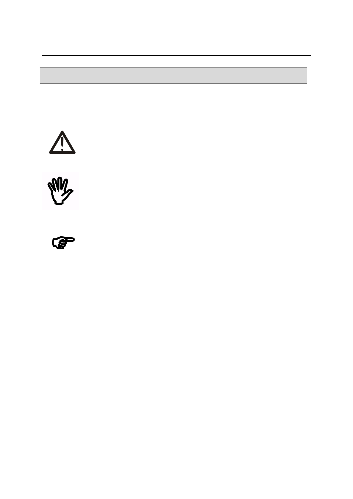
Description of visual symbols used in this user manual:
This symbol is responsible for reviewing the appropriate place in the
user instructions, warnings and important information. Failure to
follow warnings could cause injury or damage to the device
Important information and guidelines
Following this guidelines makes the use of the device easier
Attention: The screenshots in this manual can be dissimilar from actual images
at the time of the device purchase. Due to continuous development of the devices
software, some of the functions may differ from these in the manual. The manufacturer
claims no responsibility for any undesirable effects (misunderstanding) caused
by changes of the software.
User manual RFID IND Modbus-Uni Page 4 of 15
[B03]

2 Application of the device
The RFID IND Modbus-Uni device is used to read RFID Unique tags.
The device is used for an integration with other systems using Modbus RTU.
3 Warranty and liability of the manufacturer
The manufacturer provides a 2-year warranty on the device. The manufacturer also
provides post-warranty service for 10 years from the date of the introducing the device
on the market. The warranty covers all defects in material and workmanship.
The manufacturer undertakes to comply with the contract of guarantee, if the following
conditions are met:
• all repairs, alterations, extensions and device calibrations are performed by the
manufacturer or authorized service,
• supply network installation meets applicable standards in this regard,
• the device is operated in accordance with the recommendations outlined in this
manual,
• the device is used as intended.
The manufacturer assumes no responsibility for consequences resulting from improper
installation, improper use of the device, not following this manual and the repairs of the
device by individuals without permission.
This device doesn’t contain serviceable parts.
User manual RFID IND Modbus-Uni Page 5 of 15
[B03]

4 Safety guidelines
The reader has been designed and built using modern electronic components, according
to the latest trends in the global electronics. In particular, much emphasis was placed on
ensuring optimum safety and reliability of control.
The device has a housing with a high-quality plastic.
4.1 Power supply
The module is suitable for power supply 10-24VDC.
4.2 Storage, work conditions.
The reader is equipped with a sealed IP65 enclosure which means:
total resistance to foreign objects
resistance to water jet directed directly to the device
storage and operation at temperatures from -25°C to + 60°C,
4.3 Installation and use of the reader
The reader should be used following the guidelines shown in next part of the
user manual.
4.4 Utilization of the reader
When it becomes necessary to liquidate the device (for instance retiring of the device
from service), please contact the manufacturer or its representative, who are obliged to
respond, appropriately, i.e. collecting the reader from the user. You can also ask the
companies involved in utilization and/or liquidation of electrical or computer equipment.
Under no circumstances should you place the device along with other waste material.
User manual RFID IND Modbus-Uni Page 6 of 15
[B03]

5 Construction of the module
5.1 General features
The reader is equipped with an RS485 port supporting Modbus RTU protocol and a USB
port used for configuration and testing of the module.
The device has two relay outputs and two inputs.
Technical data:
Supply voltage:12-24VDC
Power supply: 15mA (12V)
Transponders:
Supported transponder standard: UNIQUE, Manchester,
Carrier frequency: 125kHz,
Reading distance up to 8cm from the directions of the device LEDs side.
Communication:
1 RS485 port – modbus RTU
1 USB port to configuration
Inputs:
number of inputs: 2
input type: opto-isolator, dry contact (NO)
Outputs:
number of outputs: 2
output type: relay NO
maximum relay current load: 1A @ 30VDC
Housing:
IP Code: IP65
Dimensions:
User manual RFID IND Modbus-Uni Page 7 of 15
[B03]

5.2 General view
5.3 Visual and sound signals
The device has been equipped with 3 LEDs indicating the module operation status and a
sound generator informing about the application of the tag.
RFID IND Modbus-Uni
Name Description
POWER Power LED
Status 1 Error
Status 2 Correct tag read
User manual RFID IND Modbus-Uni Page 8 of 15
[B03]

6 Device configuration
To configure the device use the Inveo RFID M1 / U1 Configurator software, which
allows you to define the basic functions of the device. The program can be downloaded
from https://inveo.com.pl/software.
After installing the RFID M1 / U1 Configurator configuration program and starting it,
connect the USB cable to the computer and the module (in this case, the external power
supply of the module is not required – the device is powered via the USB port).
The first line of the program window displays information about the version of the
configuration program – PC version, reader software version – RFID Software and
reader version – RFID Hardware.
It is also an information on whether the configuration program was connected to a reader
Connected / Not connected.
User manual RFID IND Modbus-Uni Page 9 of 15
[B03]

6.1 Outputs
The reader is has 2 relay outputs. Each output can be programmed separately. The fields
in the Outputs segment are used to configure the output settings.
Mode – Sets the output mode. The output can work in the following modes:
• Disable – output is disabled,
• Bistable mode – a relay has one determined status (is engaged or disengaged).
• Astable mode – if the channel will be enabled, the relay is engage and disengage
cyclically. Time of engage and disengage relay:
- Time On – time when a relay is engaged,
- Time Off – time when a relay is disengaged.
• TIME – the output will enable for the Time ON and then the output will disable
(e.g. the control of the electromagnet).
User manual RFID IND Modbus-Uni Page 10 of 15
[B03]
t
on
t
off
t
on
t
off
t
on
t
off
t
on
t
on
t
off
t
on
t
off
t
on
t
off
t
on
t
on

Power ON – the state of the output after powering the device
• Active – output enabled,
• Inactive – output disabled.
State – visualization of the output, if a rectangle is yellow it means that the output
current is turned on.
Buttons Out 1 and Out 2 outputs can activate or deactivate the output.
Active Relay on Card – if the TAG will be read, the output enables.
To set the duration of the active output it is necessary to select the TIME mode and set
appropriate Time ON.
6.2 Inputs
Fields STATE INPUT 1 and STATE INPUT 2 displays the actual state of inputs. Square
field in black – input inactive, field in yellow – active input.
6.3 LEDs and sound signaling control
The RFID M1/U1 Configurator allows user to customize visual and sound indication.
All you have to do is select the appropriate configuration settings and upload it to the
module.
Two options can be set for the Buzzer:
• OFF – signaling device switched off,
• ON – sound signaling at the moment of reading the TAG.
The device has 3 LEDs:
• Power supply diode, green LED,
• LED 1 – red LED,
• LED 2 – green LED.
Regardless of the selected setting, it is always possible to control the signaling
via the Modbus RTU protocol.
User manual RFID IND Modbus-Uni Page 11 of 15
[B03]

6.4 Continuous Read Mode
The device allows the user to define the delay of reading TAGs.
The Continuous Read Mode means that the same TAG can be read only after
the defined time has elapsed but another TAG is read immediately. This means that
the same card will not be accidentally read several times. (30 = 3 seconds)
Attention! If the user uses this option, the read flag of the new TAG will NOT appear.
The device will operate autonomously and automatically allow another reading of the
same TAG after the declared time.
6.5 RS485 – Configuration of transmission
The RS485 section is used to configure device communication.
MODE (setting of 9th bit of transmission):
None
Even – parity bit
Odd – odd bit
BaudRate – transmission speed (1200, 2400, 4800, 9600, 19200, 38400, 57600,
115200)
Device Address – device address for Modbus protocol
Attention! After customizing the settings and saving in the device, it is
necessary to restart the device.
User manual RFID IND Modbus-Uni Page 12 of 15
[B03]

7 Modbus RTU
Supported Modbus functions
The device supports the following MODBUS functions:
- 0x01 Read Coils,
- 0x03 Read Holding Register,
- 0x05 Write Single Coil,
- 0x06 Write Single Register,
- 0x0F Write Multiple Coils,
- 0x10 Write Multiple Registers.
For the correct work operation of the device and Modbus protocol,
the RFID M1 / U1 Configurator must be closed!
7.1 Modbus Holding Registers addresses
Address R/W Description
1000 R/W IsNewTag – the tag has been read
1 – a new tag
0 – no tag
Flag must be reset (clear to 0) before read next tag.
Same as Single Coil Register 1016.
1001 R UID Length – length of the UID
1002 -1011 R UID – UID number
1017 R MODEL ID – ID of the device
1018 R Software Version
1019 R Hardware Version
1020 R/W Mode OUT1 – output number 1 mode:
0 – Disable – output disabled
1 – Bistable – bistable mode
2 – Astable – astable mode
3 – Time – enable the output for Ton time
1021 R/W Time On OUT1 – time determining how long the output will be
enabled (1-65535) (*0,1 sec)
120 means 12 seconds
1022 R/W Time Off OUT1 – time determining how long the output will be
disabled (1-65535) (*0,1 sec)
120 means 12 seconds
1023 R/W Mode OUT2 – output number 2 mode, as above
1024 R/W Time On OUT2 – as above
1025 R/W Time Off OUT2 – as above
User manual RFID IND Modbus-Uni Page 13 of 15
[B03]

7.2 Modbus Single Coil addresses
Address R/W Description
1000 R/W ON 1 – control relay 1 (off/on)
1001 R/W ON 2 – control relay 1 (off/on)
1002 R COIL STATE 1 – relay 1 coil state
1003 R COIL STATE 2 – relay 2 coil state
1010 R INPUT 1 – input 1 state
1011 R INPUT 2 – input 2 state
1012 R/W LED1 – control LED 1
1013 R/W LED2 – control LED 2
1014 W BUZZ ACCEPT – enable accept sound
1015 W BUZZ REJECT – enable reject sound
1016 R/W IsNewTag – the tag has been read
1 – a new tag
0 – no tag
Flag must be reset (clear to 0) before read next tag.
Same as Holding Register 1000.
1017 R/W ResetFlag:
1 – default state for power-on reader
It can be clear and set by user for diagnostic purpose
The most frequently checked is Single Coil 1016. If its value changes to 1, it means
that the device has read the new tag. Holding Registers 1002-1011 registers contain the
ID of the tag.
When you read ID number you should release Coil 1016 (or Holding Reg 1000) flag
(clear to 0). Only after that the reader is able to read next ID tag.
Modification of the output parameters can be done by the Modbus protocol. It is not
stored in the module's permanent memory. That means after reboot, the output
parameters previously saved to the EEPROM by the configuration program will be
restored.
User manual RFID IND Modbus-Uni Page 14 of 15
[B03]

8 Description of terminals
The view of the PCB is shown in the figure below.
Name Description
Power Power connector 12-24VDC
OUT 1 Relay output 1
OUT 2 Relay output 2
IN 1 Input 1
IN 2 Input 2
USB USB port – module configuration
RS485 Connector RS485 MODBUS
Boot Shortening the BOOT pins when power is applied causes the module
to enter the bootloader mode
User manual RFID IND Modbus-Uni Page 15 of 15
[B03]
 Loading...