

Inventor Air Conditioners L4VI32-18, L4VO32-18, L4VI32-24, L4VO32-24, L4VI32-16 Service Manual
...
• SERVICE MANUAL
ENGLISH
WALL MOUNTED UNIT
AIR CONDITIONING SYSTEMS
MODELS:
L4VI32-18/L4VO32-18
L4VI32-24/L4VO32-24

Service Manual
Service Manual
Table of Contents
Service Manual
Table of Contents
Part
Ⅰ
: Technical Information
.......................................................................1
1. Summary
......................................................................................................................1
..........................................................................................................2
...........................................................................................................3
2.2 Operation Characteristic Curve ........................................................................................6
2.3 Capacity Variation Ratio According to Temperature ....................................................... ..6
2.4 Cooling and Heating Data Sheet in Rated Frequency .....................................................7
2.5 Noise Curve ......................................................................................................................8
3. Outline Dimension Diagram
.........................................................................................9
3.1 Indoor Unit ........................................................................................................................9
3.2 Outdoor Unit ...................................................................................................................10
4. Refrigerant System Diagram
....................................................................11
5. Electrical Part
.........................................................................................................12
5.1 Wiring Diagram ...............................................................................................................12
5.2 PCB Printed Diagram .....................................................................................................14
6. Function and Control
......................................................................................16
6.1 Remote Controller Introduction.................... ...................................................................16
6.2 Preparation before operation................................. .........................................................16
6.3 Introduction of operation function................. ...................................................................16
6.4 Introduction of special functions................ ......................................................................18
6.4 Brief Description of Modes and Functions ......................................................................20
Part
Ⅱ
: Installation and Maintenance
.................................................29
7. Notes for Installation and Maintenance
..........................................29
8. Installation
................................................................................................................33
8.1 Installation Dimension Diagram ......................................................................................33
8.2 Installation Parts-checking ............................................................................................35
8.3 Selection of Installation Location ....................................................................................35
8.4 Requirements for electric connection .............................................................................35
8.5 Installation of Indoor Unit ................................................................................................35
8.6 Installation of Outdoor unit .............................................................................................38
8.7 Vacuum Pumping and Leak Detection ...........................................................................39
8.8 Check after Installation and Test operation ....................................................................39
Service Manual
Table of contents
Service Manual
9. Maintenance
............................................................................................................40
9.1 Malfunction Display of Indoor Unit ..................................................................................40
9.2 Procedure of Troubleshooting ........................................................................................42
9.3 Troubleshooting for Normal Malfunction .........................................................................60
10. Exploded View and Parts List
..............................................................62
10.1 Indoor Unit ....................................................................................................................62
10.2 Outdoor Unit .................................................................................................................66
11. Removal Procedure
.......................................................................................70
11.1 Removal Procedure of Indoor Unit ...............................................................................70
11.2 Removal Procedure of Outdoor Unit ............................................................................75
Appendix:
.........................................................................................................................86
Appendix 1: Reference Sheet of Celsius and Fahrenheit .....................................................86
......................................................................86
Appendix 3: Pipe Expanding Method ....................................................................................87
Appendix 4: List of resistance for Temperature Sensor .........................................................88
Technical Information
1
Service Manual
Service Manual
Part
Ⅰ
: Technical Information
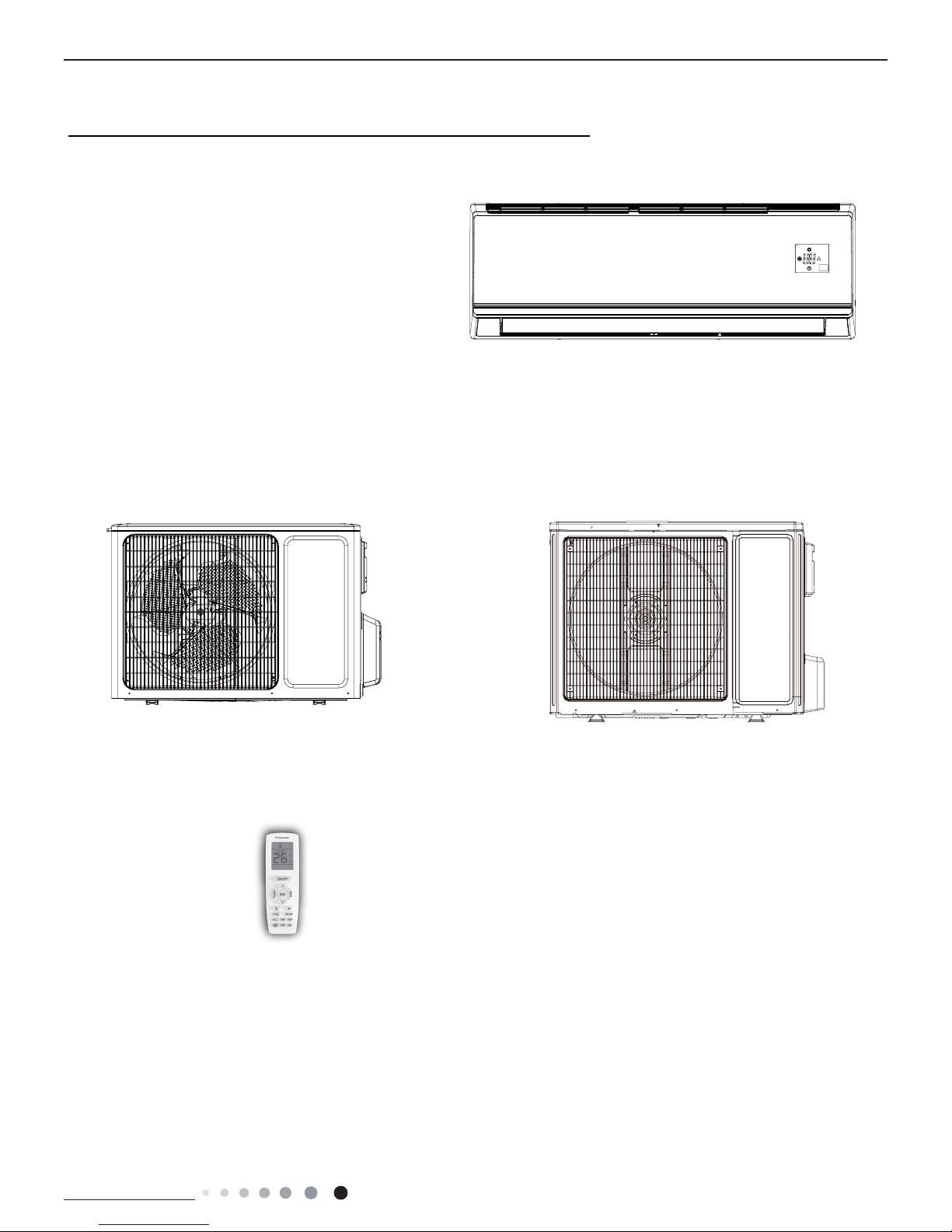
Indoor Unit
L4VI32-18
L4VI32-24
1. Summary
Outdoor Unit
L4VO32-24
L4VO32-18
Remote Controller
YAN1F1
Technical Information
2
Service Manual
Service Manual
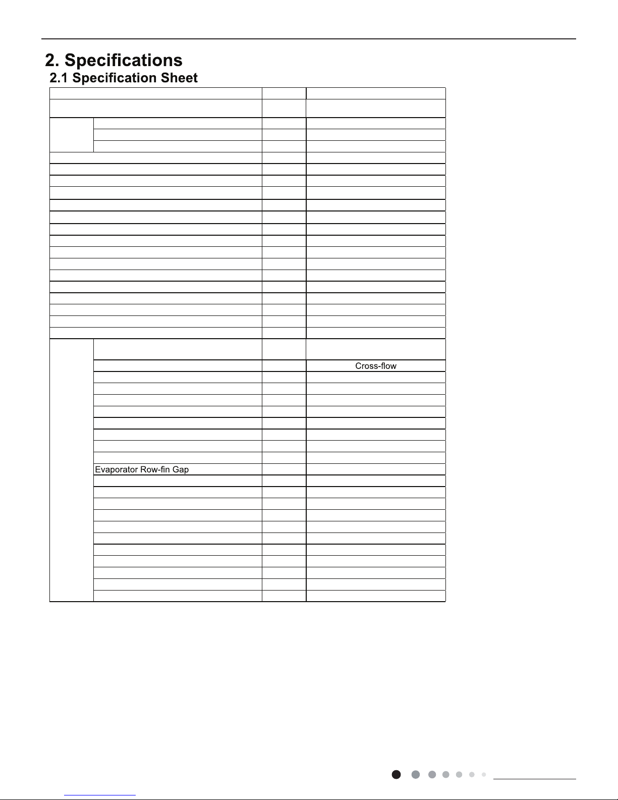
Parameter Unit Value
Model L4VI32-18
Power
Supply
Rated Voltage V~ 220-240
Rated Frequency Hz 50
Phases 1
Power Supply Mode Outdoor
Cooling Capacity W 5130
Heating Capacity W 5280
Cooling Power Input W 1580
Heating Power Input W 1420
Cooling Current Input A 7.0
Heating Current Input A 6.3
Rated Input W 2300
Rated Current A 10.8
Air Flow Volume(SH/H/M//L/SL) m
3
/h 850/720/610/520/Dehumidifying Volume L/h 1.8
EER W/W 3.25
COP W/W 3.72
SEER W/W 6.1
SCOP(Average/Warmer/Colder) W/W 4.0/5.1/3.4
Application Area m
2
23-34
Indoor
Unit
Indoor Unit Model
L4VI32-18
Fan Type
Fan Diameter Length(DXL) mm Ф106X706
Cooling Speed(SH/H/M//L/SL) r/min 1230/1130/1030/800/Heating Speed(SH/H/M//L/SL) r/min 1350/1200/1050/900/Fan Motor Power Output W 35
Fan Motor RLA A 0.35
Fan Motor Capacitor μF 2.5
Evaporator Form Aluminum Fin-copper Tube
Evaporator Pipe Diameter mm Ф7
mm 2-1.4
Evaporator Coil Length (LXDXW) mm 715X25.4X304.8
Swing Motor Model MP35CJ
Swing Motor Power Output W 2.5
Fuse Current A 3.15
Sound Pressure Level(SH/H/M//L/SL) dB (A) 49/44/39/34/Sound Power Level(SH/H/M//L/SL) dB (A) 59/54/49/44/Dimension (WXHXD) mm 970X300X224
Dimension of Carton Box (LXWXH) mm 1038X380X305
Dimension of Package(LXWXH) mm 1041X383X320
Net Weight kg 13.5
Gross Weight kg 16.5
Technical Information
3
Service Manual
Service Manual
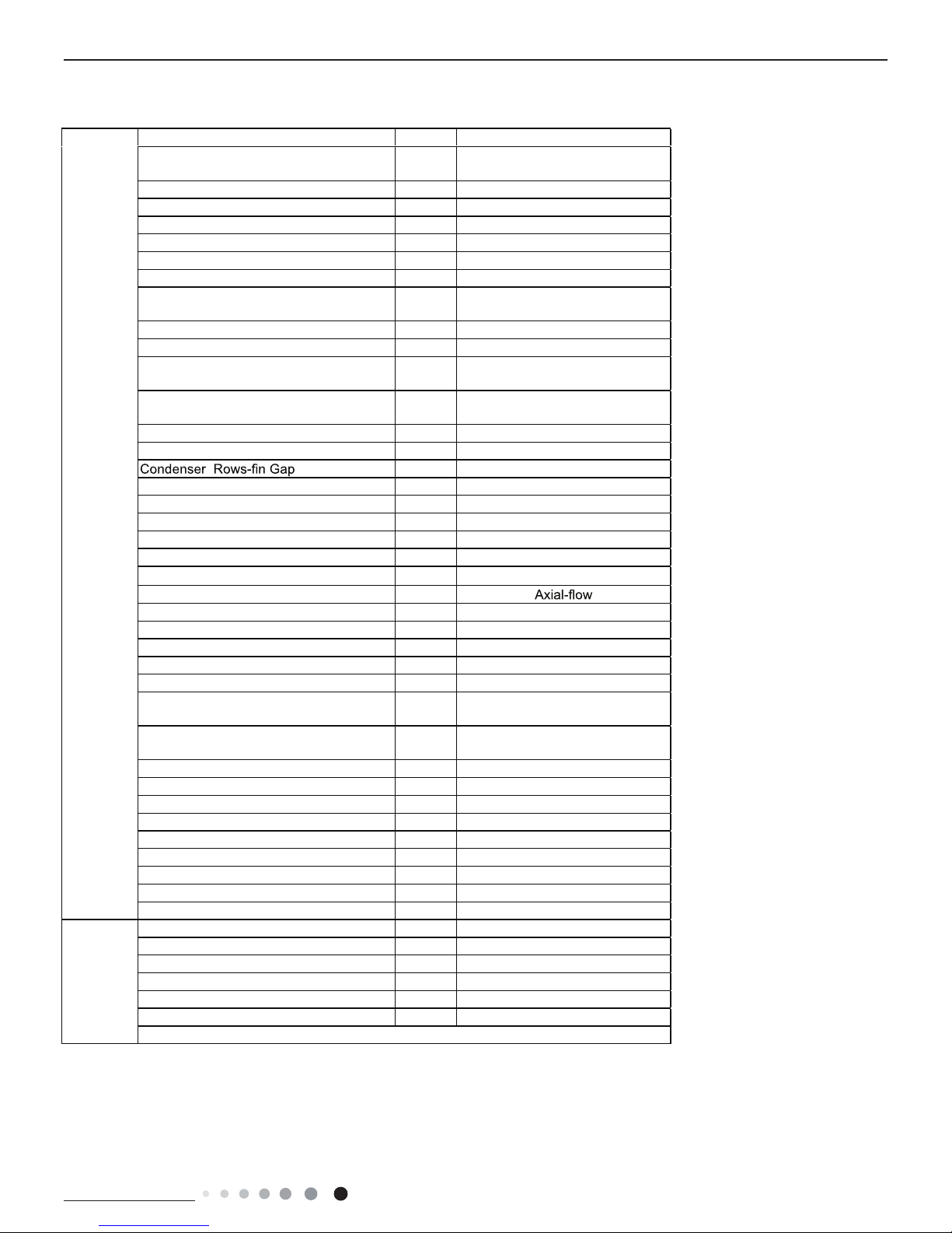
Outdoor
Unit
Outdoor Unit Model L4VO32-18
Compressor Manufacturer
ZHUHAI LANDA COMPRESSOR
CO.,LTD
Compressor Model QXF-B141ZF030A
Compressor Oil 68DA
Compressor Type Rotary
Compressor LRA. A 25
Compressor RLA A 6.5
Compressor Power Input W 1410
Compressor Overload Protector
1NT11L-6233/KSD115℃/HPC
115/95
Throttling Method Electron expansion valve
Set Temperature Range ºC 16~30
Cooling Operation Ambient Temperature
Range
ºC -15~43
Heating Operation Ambient Temperature
Range
ºC -15~24
Condenser Form Aluminum Fin-copper Tube
Condenser Pipe Diameter mm Φ7.94
mm 2-1.4
Condenser Coil Length (LXDXW) mm 742X38.1X550
Fan Motor Speed rpm 780
Fan Motor Power Output W 40
Fan Motor RLA A 0.62
Fan Motor Capacitor μF /
Outdoor Unit Air Flow Volume m
3
/h 2400
Fan Type
Fan Diameter mm Ф445
Defrosting Method Automatic Defrosting
Climate Type T1
Isolation I
Moisture Protection IPX4
Permissible Excessive Operating Pressure
for the Discharge Side
MPa 4.3
Permissible Excessive Operating Pressure
for the Suction Side
MPa 2.5
Sound Pressure Level (H/M/L) dB (A) 56/-/Sound Power Level (H/M/L) dB (A) 64/-/Dimension(WXHXD) mm 899X596X378
Dimension of Carton Box (LXWXH) mm 945X417X630
Dimension of Package(LXWXH) mm 948X420X645
Net Weight kg 39
Gross Weight kg 42
Refrigerant R32
Refrigerant Charge kg 0.9
Connection
Pipe
Connection Pipe Length m 5
Connection Pipe Gas Additional Charge g/m 16
Outer Diameter Liquid Pipe mm Ф6
Outer Diameter Gas Pipe mm Ф12
Max Distance Height m 10
Max Distance Length m 25
Note: The connection pipe applies metric diameter.
The above data is subject to change without notice. Please refer to the nameplate of the unit.
Technical Information
4
Service Manual
Service Manual
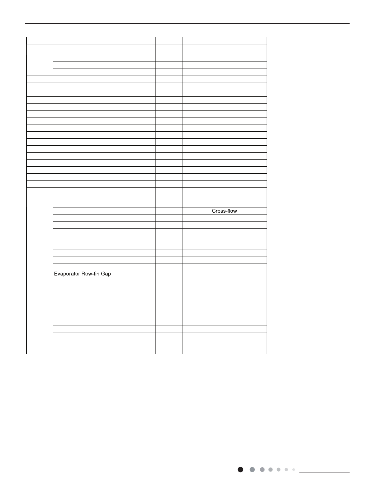
Parameter Unit Value
Model L4VI32-24
Power
Supply
Rated Voltage V~ 220-240
Rated Frequency Hz 50
Phases 1
Power Supply Mode Outdoor
Cooling Capacity W 6450
Heating Capacity W 6450
Cooling Power Input W 1950
Heating Power Input W 1735
Cooling Current Input A 8.4
Heating Current Input A 8.0
Rated Input W 3100
Rated Current A 13.04
Air Flow Volume(SH/H/M//L/SL) m
3
/h 1250/1050/950/850/Dehumidifying Volume L/h 2.0
EER W/W 3.3
COP W/W 3.71
SEER W/W 6.30
SCOP(Average/Warmer/Colder) W/W 4.0/5.1/3.3
Application Area m
2
23-34
Indoor
Unit
Indoor Unit Model
L4VI32-24
Fan Type
Fan Diameter Length(DXL) mm Φ108X830
Cooling Speed(SH/H/M//L/SL) r/min 1250/1000/900/800/Heating Speed(SH/H/M//L/SL) r/min 1250/1000/900/850/Fan Motor Power Output W 35
Fan Motor RLA A 0.35
Fan Motor Capacitor μF 3
Evaporator Form Aluminum Fin-copper Tube
Evaporator Pipe Diameter mm Ф7
mm 2-1.4
Evaporator Coil Length (LXDXW) mm 845X25.4X342.9
Swing Motor Model MP35CJ
Swing Motor Power Output W 2.5
Fuse Current A 3.15
Sound Pressure Level(SH/H/M//L/SL) dB (A) 49/44/41/39/Sound Power Level(SH/H/M//L/SL) dB (A) 63/59/56/53/Dimension (WXHXD) mm 1078X325X246
Dimension of Carton Box (LXWXH) mm 1145X410X335
Dimension of Package(LXWXH) mm 1148X413X350
Net Weight kg 16.5
Gross Weight kg 20
Technical Information
5
Service Manual
Service Manual
Outdoor
Unit
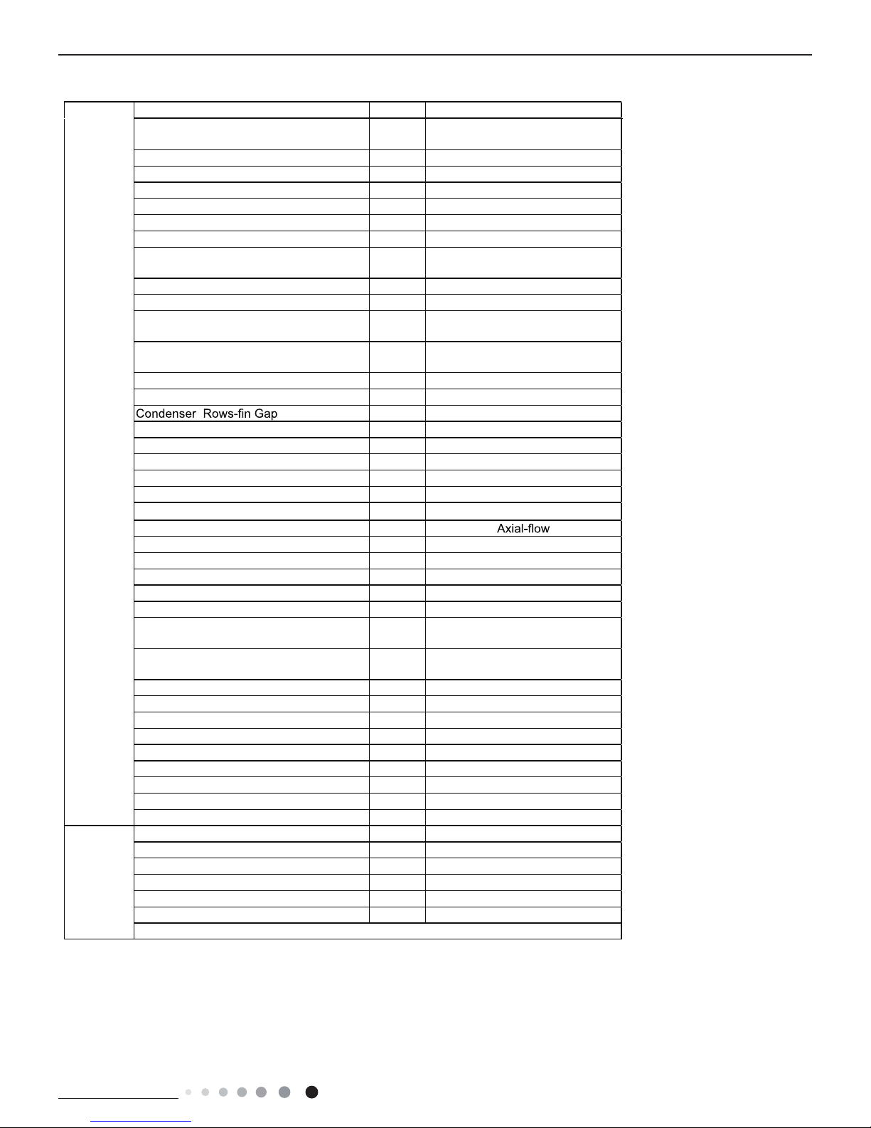
Outdoor Unit Model L4VO32-24
Compressor Manufacturer
ZHUHAI LANDA COMPRESSOR
CO,LTD.
Compressor Model QXFS-D23zX090A
Compressor Oil FW68DA
Compressor Type Rotary
Compressor LRA. A 25
Compressor RLA A 11.50
Compressor Power Input W 2400
Compressor Overload Protector
1NT11L-6233 or HPC115/95/ or
KSD115ºC
Throttling Method Electron expansion valve
Set Temperature Range ºC 16~30
Cooling Operation Ambient Temperature
Range
ºC -15~43
Heating Operation Ambient Temperature
Range
ºC -15~24
Condenser Form Aluminum Fin-copper Tube
Condenser Pipe Diameter mm Φ7
mm 2-1.4
Condenser Coil Length (LXDXW) mm 935X38.1X660
Fan Motor Speed rpm 800
Fan Motor Power Output W 60
Fan Motor RLA A 0.58
Fan Motor Capacitor μF /
Outdoor Unit Air Flow Volume m
3
/h 3200
Fan Type
Fan Diameter mm Ф520
Defrosting Method Automatic Defrosting
Climate Type T1
Isolation I
Moisture Protection IPX4
Permissible Excessive Operating Pressure
for the Discharge Side
MPa 4.3
Permissible Excessive Operating Pressure
for the Suction Side
MPa 2.5
Sound Pressure Level (H/M/L) dB (A) 58/-/Sound Power Level (H/M/L) dB (A) 68/-/Dimension(WXHXD) mm 963X700X396
Dimension of Carton Box (LXWXH) mm 1026X455X735
Dimension of Package(LXWXH) mm 1029X458X750
Net Weight kg 52.5
Gross Weight kg 57
Refrigerant R32
Refrigerant Charge kg 1.7
Connection
Pipe
Connection Pipe Length m 5
Connection Pipe Gas Additional Charge g/m 50
Outer Diameter Liquid Pipe mm Ф6
Outer Diameter Gas Pipe mm Ф16
Max Distance Height m 10
Max Distance Length m 25
Note: The connection pipe applies metric diameter.
The above data is subject to change without notice. Please refer to the nameplate of the unit.

Technical Information
6
Service Manual
Service Manual
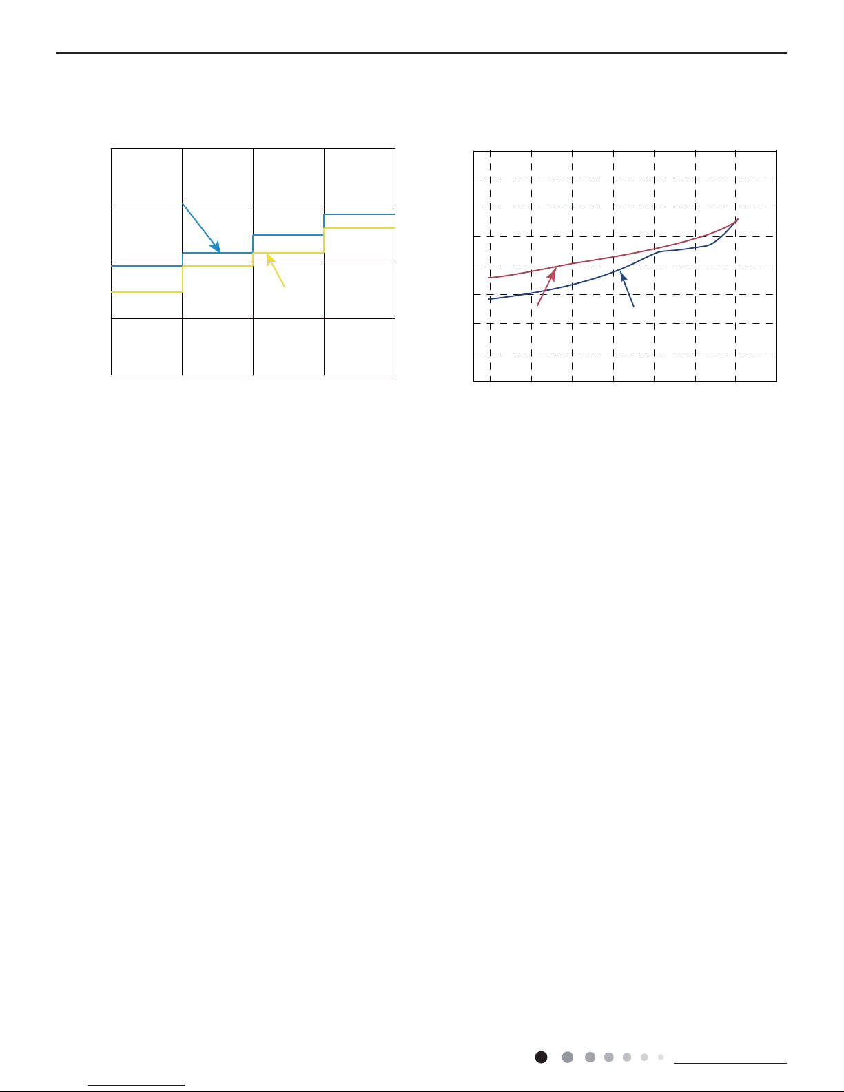
2.2 Operation Characteristic Curve
2.3 Capacity Variation Ratio According to Temperature
0 10 20 30 40 50 60 70 90 0 10 20 30 40 50 60 70 80 90 100
120
110
80
11
10
9
8
7
6
5
4
3
2
1
0
Compressor speed (rps)
)A(tner ruC
11
10
9
8
7
6
5
4
3
2
1
0
Compressor speed (rps)
)A(tner ruC
220V
230V
240V
220V
230V
240V
Conditions
Indoor: DB27°C/WB19°C
Outdoor: DB35°C/WB24°C
Indoor air flow: High
Pipe length: 5m
Conditions
Indoor: DB20°C/WB15°C
Outdoor: DB7°C/WB6°C
Indoor air flow: High
Pipe length: 5m
Cooling Heating
Cooling Heating
32 33 34 35 36 37 38 39 43 –15 –10 –5
40 41 42
100
105
95
90
85
80
75
70
65
60
55
50
110
100
90
80
70
60
50
40
0 57 1
0
Conditions
Indoor:DB27°C/WB19°C
Indoor air flow:Super High
Pipe length: 5m
Conditions
Indoor:DB20°C/WB15°C
Indoor air flow:Super High
Pipe length: 5m
Outdoor temp.(°C) Outdoor temp.(°C)
Capacity ratio (%)
Capacity ratio (%)
Cooling Heating
Heating operation ambient temperature range is -15°C~24°C

Technical Information
7
Service Manual
Service Manual
2.4 Cooling and Heating Data Sheet in Rated Frequency
Rated cooling
condition(°C)
(DB/WB)
Model
Pressure of gas pipe
connecting indoor and
outdoor unit
Inlet and outlet pipe
temperature of heat
exchanger
Fan speed of
indoor unit
Fan speed of
outdoor unit
Compressor
frequency
(Hz)
Indoor Outdoor P (MPa) T1 (°C) T2 (°C)
27/19 35/24
18K
0.9 to 1.1 12 to 14 75 to 37 Super High High
52
24K 72
Rated heating
condition(°C)
(DB/WB)
Model
Pressure of gas pipe
connecting indoor and
outdoor unit
Inlet and outlet pipe
temperature of heat
exchanger
Fan speed of
indoor unit
Fan speed of
outdoor unit
Compressor
frequency
(Hz)
Indoor Outdoor P (MPa) T1 (°C) T2 (°C)
20/- 7/6
18K
2.2 to 2.4 70 to 35 2 to 4 Super High High
65
24K 77
Instruction:
T1: Inlet and outlet pipe temperature of evaporator
T2: Inlet and outlet pipe temperature of condenser
P: Pressure at the side of big valve
Connection pipe length: 5m.
Cooling:
Heating:
Technical Information
8
Service Manual
Service Manual
2.5 Noise Curve
Indoor side noise when blowing Outdoor side noise when blowing
Indoor fan motor rotating speed
Compressor frequency(Hz)
Noise/dB(A)
50
60
30
40
20
Low
Middle
High
Super High
50
52
54
56
58
60
62
64
68
20 03045060708
090
Noise dB(A)
18K
24K
24K
18K
Technical Information
9
Service Manual
Service Manual
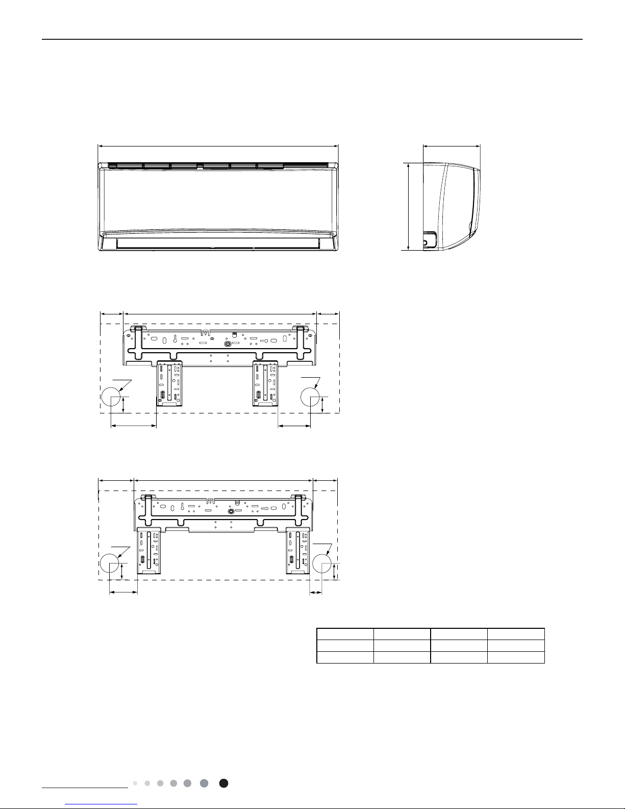
3. Outline Dimension Diagram
3.1 Indoor Unit
W
24K
18K
D
H
79
154
43
206 685 187
Φ70
Φ70
43
104 685 181
140
190
38
Φ55
Φ55
38
Model W
HD
18K970 30
02
24
24K1078 325246
Unit:m
m
Technical Information
10
Service Manual
Service Manual
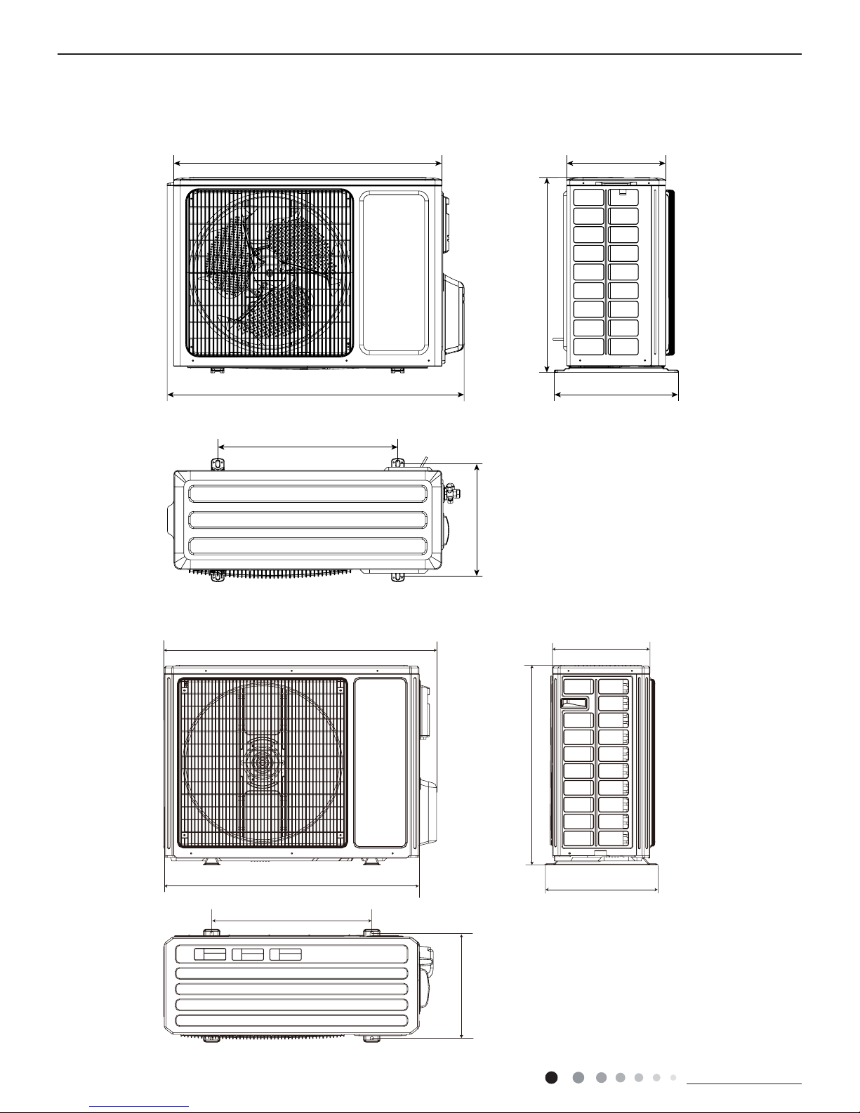
899
818
596
378
303
343
550
Unit:mm
340
963
700
396
890
560
364
Unit:mm
3.2 Outdoor Unit
18K
24K
Technical Information
11
Service Manual
Service Manual
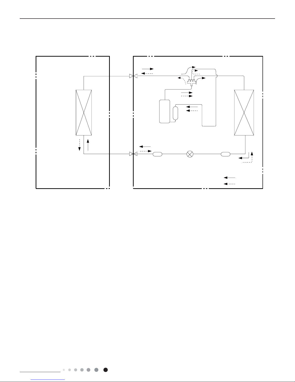
4. Refrigerant System Diagram
Connection pipe specication:
Liquid pipe:1/4" (6mm)
Gas pipe:1/2" (12mm) 18K
Gas pipe:5/8" (16mm) 24K
Indoor unit
Outdoor unit
COOLING
HEATING
4-Way valve
Discharge
Suction
Heat
exchanger
(evaporator)
Heat
exchanger
(condenser)
Valve
Valve
Liquid pipe
side
Gas pipe
side
Strainer Electric
expand
valve
Strainer
Compressor
Accumlator
Technical Information
12
Service Manual
Service Manual
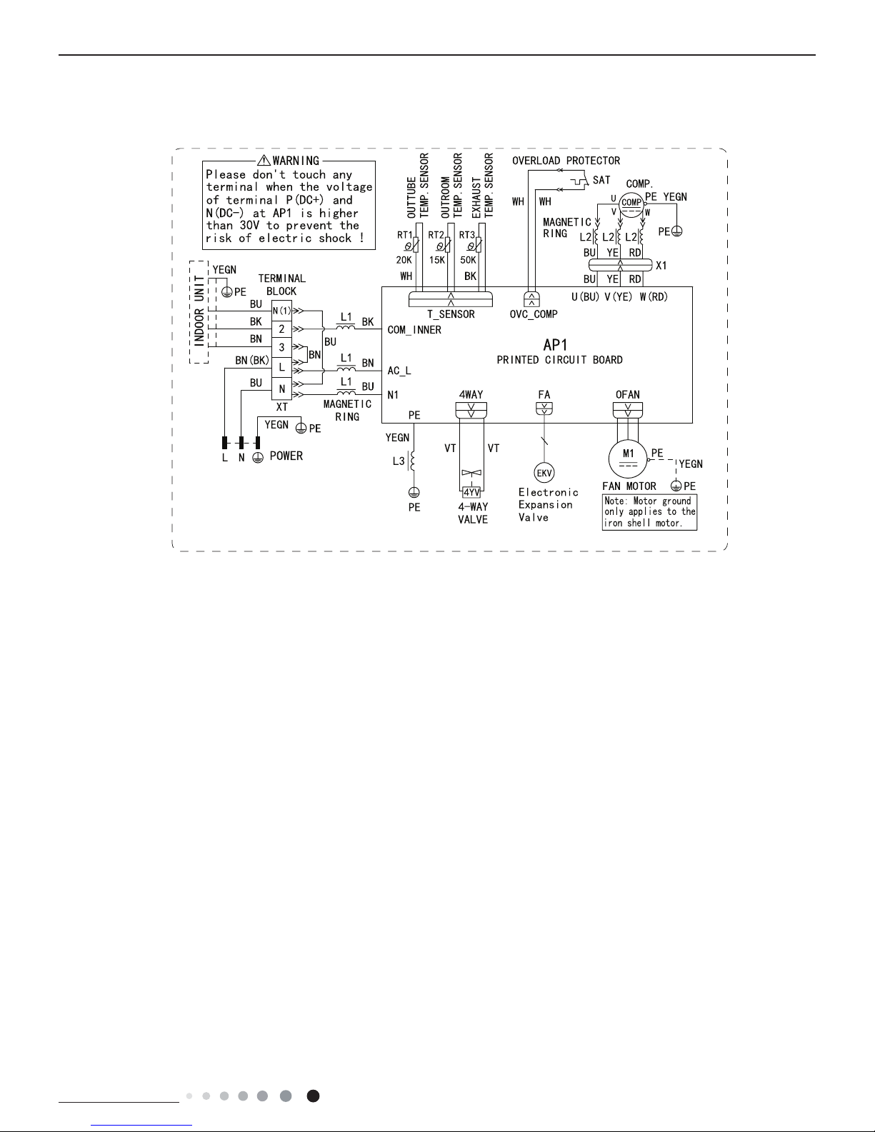
These circuit diagrams are subject to change without notice, please refer to the one supplied with the unit.
L4VO32-18, L4VO32-24
● Outdoor Unit
63610000218
Service Manual
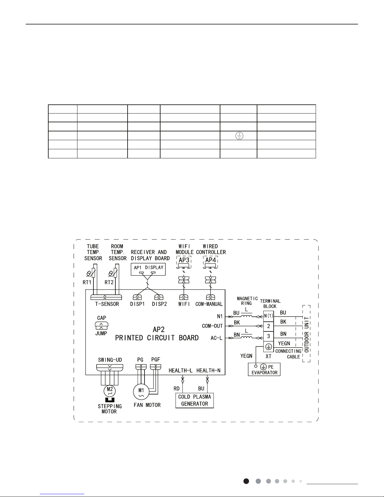
5. Electrical Part
5.1 Wiring Diagram
● Indoor Unit
● Instruction
Symbol Symbol Color Symbol Symbol Color Symbol Name
WH White GN Green CAP Jumper cap
YE Yellow BN Brown COMP Compressor
RD Red BU Blue Grounding wire
YEGN Yellow/Green BK Black / /
VT Violet OG Orange / /
Note: Jumper cap is used to determine fan speed and the swing angle of horizontal lover for this model.
600007000688
L4VI32-18, L4VI32-24
Technical Information
13
Service Manual
Service Manual
These circuit diagrams are subject to change without notice, please refer to the one supplied with the unit.
L4VO32-18, L4VO32-24
● Outdoor Unit
63610000218
Technical Information
14
Service Manual
Service Manual
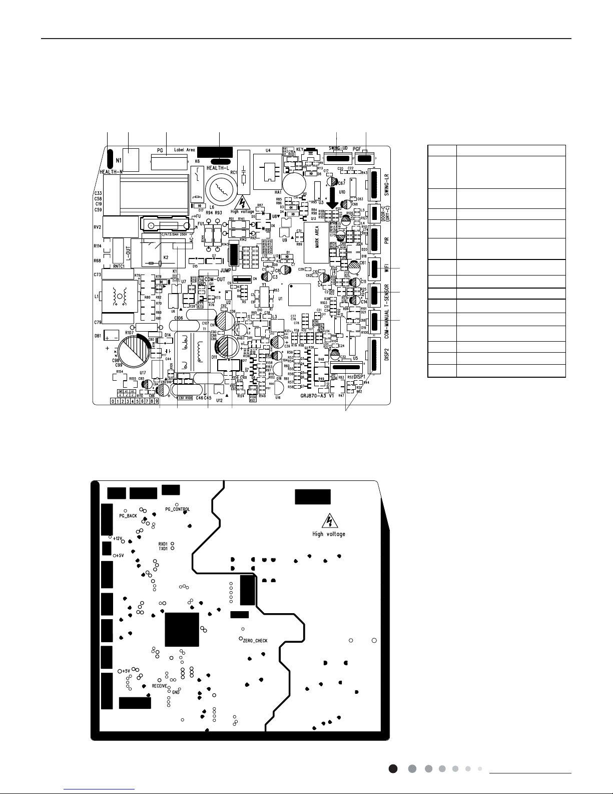
5.2 PCB Printed Diagram
Indoor Unit
1
2 456
7
8
9
1011121314
3
● Top view
● Bottom view
No.Name
1
2
3
4
Interface of health function
live wire
5
Interface of up&down swing
motor
Interface of PG feedback
6
Neutral wire interface of cold
plasma(only for the mode
with this function)
7
WIFI
8Temperature sensor
Wired controller
9
10
Interface of diaplay
11
12 Communication wire
Jumper cap
13
Live wire
14 Fuse
Neutral wire interface of
power supply
Interface of indoor fan
Technical Information
15
Service Manual
Service Manual
Outdoor Unit
● Top view
● Bottom view
No. Name
1
2
3
4
Interface of temperature sensor
5
6
7
8
9
10
11
12
123456 78910
11
12
13
14
15
Compressor three phase input
interface
Terminal of system high pressure
protection
Compressor overload protection
terminal
Terminal of electronic expansion
valve
Terminal for low pressure protection
Interface of fan
4-way valve terminal
2-way valve terminal
Terminal of compressor electric heater
Terminal of chassis electric heater
Live wire
13 Communication wire
14 Grounding wire
15 Neutral wire
Technical Information
16
Service Manual
Service Manual
Service Manual
6. Function and Control
6.1 Remote Controller Introduction
No. Button name Function
1 ON/OFF Turn on or turn off the unit
2 TURBO Set turbo function
3 MODE Set operation mode
4
Set up&down swing status
5 I FEEL Set I FEEL function
6 TEMP Switch temperature displaying type on the unit’s display
7
Set health function and air function
8 LIGHT Set light function
9 X-FAN Set X-FAN function
10 SLEEP Set sleep function
11 CLOCK Set clock of the system
12 TOFF Set timer off function
13 TON Set timer on function
14
Set left&right swing status
15 FAN Set fan speed
16 / Set temperature and time
6.2 Preparation before operation
When using the remote controller for the first time or after replacing the batteries,
please set the time of the system according to current time in the following steps:
(1).
Pressing CLOCK button, is blinking.
(2).
Pressing or button, the clock time will increase or decrease rapidly.
(3).
Press CLOCK button again to confirm the time and return to display current time.
6.3 Introduction of operation function
(1).
Selecting operation mode
In unit on status, press MODE button to select operation mode in following sequence:
(2).
Setting temperature
In unit on status, press
button to increase setting temperature and press button to decrease setting temperature. The
Note: Under auto mode, manual adjustment of temperature is not needed.
range of temperature is from 16ºC to 30ºC.
(3).
Adjusting fan speed
In unit on status, press FAN button to adjust fan speed in following sequence:
Notes:
①.
When operation mode changes, fan speed is memoried;
②.
Under dry mode, fan speed is low and can not be adjusted.
(4).
Setting swing function
Setting left&right swing
1).
Under simple swing status, press button to adjust left&right swing status;
Technical Information
17
Service Manual
Service Manual
2).
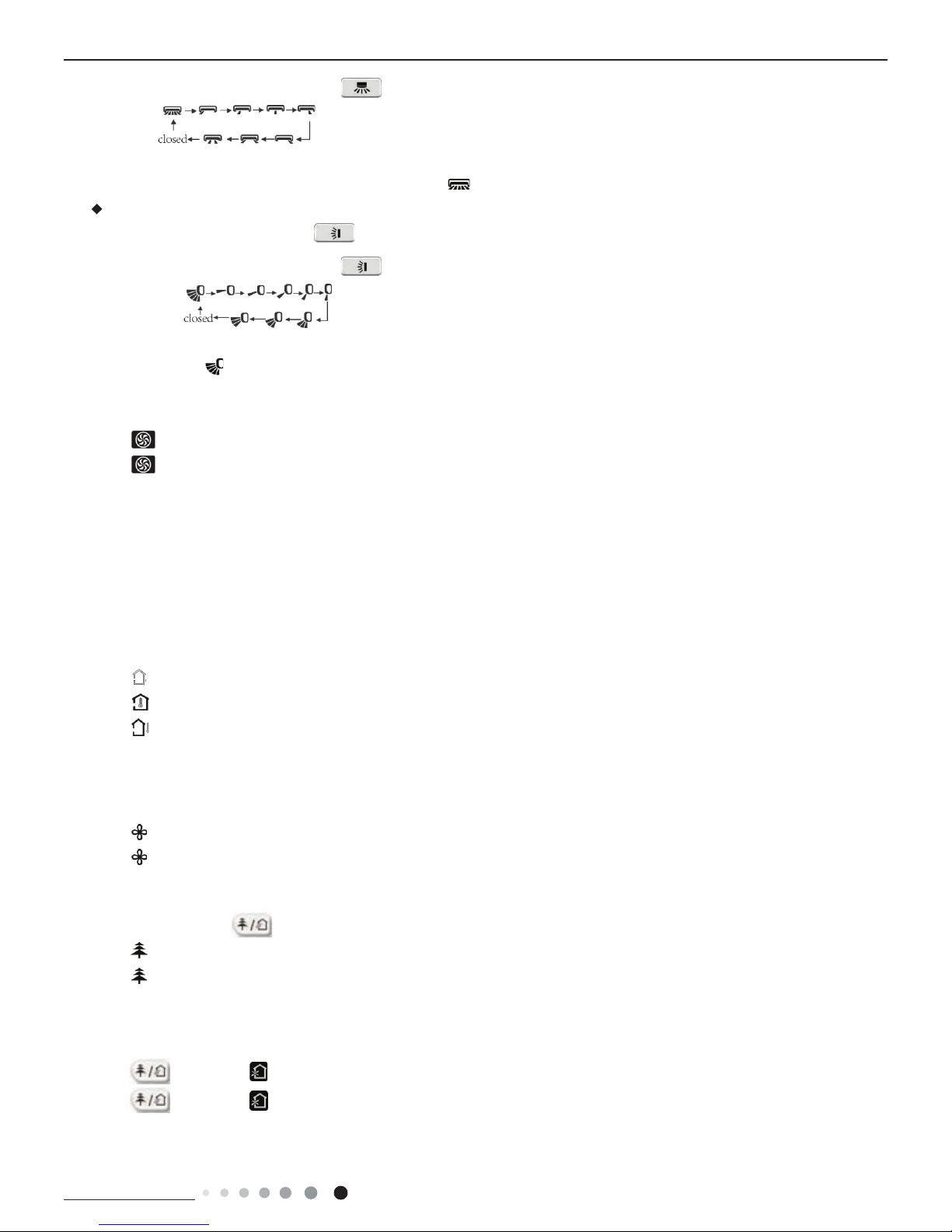
Under fixed-angle swing status, press button to adjust left&right swing angle circularly as below:
Note: operate continuously left&right swing in 2 seconds, swing states will change
according to above-mentioned order, or switch closed state and
state.
Setting up&down swing
1).
Under simple swing status, press button to adjust up&down swing status;
2).
Under fixed-angle swing status, press button to adjust up&down swing angle circularly as below:
Note: operate continuously left&right swing in 2 seconds, swing states will change according to above-mentioned order, or switch
closed state and state
(5).
Setting turbo function
Under cool or heat mode, press TURBO button to set turbo function.
When
is displayed, turbo function is on.
When
is not displayed, turbo function is off.
When turbo function is on, the unit operates in super high speed to achieve quick cooling or heating. When turbo function is off,
the unit operates in setting fan speed.
(6).
Setting light function
The light on the receiver light board will display present operation status. If you want to turn
off the light, please press LIGHT button. Press this button again to turn on the light.
(7).
Viewing ambient temperature
In unit on status, receiver light board or wired controller is defaulted to display setting
temperature. Press TEMP
button to view indoor or outdoor ambient temperature.
When
is displayed, it means the displayed temperature is setting temperature.
When
is displayed, it means the displayed temperature is indoor ambient temperature.
When is displayed, it means the displayed temperature is outdoor ambient temperature.
Note: setting temperature is always displayed in Remote Controller.
(8).
Setting X-FAN function
In cool or dry mode, press X-FAN button to set X-FAN function.
When
is displayed, X-FAN function is on.
When
is not displayed, X-FAN function is off.
When X-FAN function is on, the water on the evaporator will be blown away until turning off the unit to avoid mildew.
(9).
Setting health function
In unit on status, press
button to set health function.
When
is displayed, health function is on.
When
is not displayed, health function is off.
Health function is available when the unit is equipped with anion generator. When health function is on, the anion generator will start
operation, adsorbing the dusts and killing the bacteria in the room.
(10).
Setting air function
Press
button until is displayed, then air function is turned on.
Press
button until is disappeared, then air function is turned off.
When the indoor unit is connected with fresh air valve, air function setting can control the connection of fresh air valve, which can
control the fresh air volume and improve the air quality inside the room.
Technical Information
18
Service Manual
Service Manual
(11).
Setting sleep function
In unit on status, press SLEEP button to turn on or turn off sleep function.
When
is displayed, sleep function is on.
When
is not displayed, sleep function is off.
Notes:
①.
Sleep function can not be set in auto and fan mode;
②.
When turning off the unit or switching mode, sleep function is cancelled;
(12).
Setting I FEEL function
In unit on status, press I FEEL button to turn on or turn off I FEEL function.
When
is displayed, I FEEL function is on.
When
is not displayed, I FEEL function is off.
When I FEEL function is turned on, the unit will adjust temperature according to the temperature detected by the remote controller
to achieve the best air-conditioning effect. In this case, you should place the remote controller within the valid receiving range.
(13).
Setting timer
You can set the operation time of unit as you need. You can also set timer on and timer off in combination.
Before setting, check if the time of the system is the same as the current time. If not, please set the time according to current time.
1).
Setting timer off
①.
Pressing TOFF button, “OFF” is blinking and time displaying zone displays the timer time of last setting
②.
Press or button to adjust the timer time.
③.
Press TOFF button again to confirm setting. OFF is displayed and time displaying zone resumes to display current time.
④.
Press TOFF button again to cancel timer and OFF is not displayed.
2).
Setting timer on
①.
Pressing TON button, “ON” is blinking and time displaying zone displays the timer time of last setting.
②.
Press or button to adjust the timer time.
③.
Press TON button again to confirm setting. ON is displayed and time displaying zone resumes to display current time.
④.
Press TON button again to cancel timer and ON is not displayed.
6.4 Introduction of special functions
(1).
Setting child lock
Press
and button simultaneously to lock the buttons on remote controller and is displayed.
Press
and button simultaneously again to unlock the buttons on remote controller and is not displayed.
If the buttons are locked,
blinks 3 times when pressing the button and any operation on the button is invalid.
(2).
Switching temperature scale
In unit off status, press MODE button and
button simultaneously to switch temperature scale between ºC and ºF.
(3).
Setting energy-saving function
In unit on status and under cool mode, press CLOCK and TEMP button
simultaneously to enter energy-saving mode.
u When
is displayed, energy-saving function is on.
u When
is not displayed, energy-saving function is off.
If you want to turn off the energy-saving function, press CLOCK and TEMP button and is not displayed.
Note: energy-saving function is only available in cooling mode and it will be exited when switching mode or setting sleep function.
(4).
Absence function
In unit on status and under heat mode, press CLOCK and TEMP button simultaneously to enter absence function.
Press CLOCK and TEMP button simultaneously again to exit absence function.
Temperature displaying zone resumes previous display and is not displayed.
Temperature displaying zone displays 8 and is displayed.
Technical Information
19
Service Manual
Service Manual
In winter, absence function can keep the indoor ambient temperature above 0ºC to avoid freezing.
Note: Absence function is only available in heating mode and it will be exited when switching mode or setting sleep function.
(1).
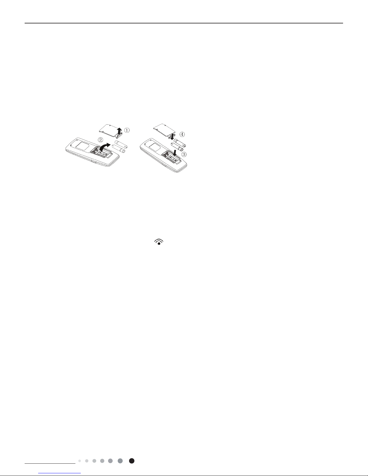
Lift the cover along the direction of arrow (as shown in Fig 1①).
(2).
Take out the original batteries (as shown in Fig 1②).
(3).
Place two 7# (AAA 1.5V) dry batteries, and make sure the position of “+” polar
and “ -” polar is correct (as shown in Fig 2 ③).
(4).
Reinstall the cover (as shown in Fig 2④).
Fig.1 Fig.2
Notes:
①.
The remote controller should be placed 1m away from the TV set or stereo sound sets.
②.
.egnar gniviecer sti nihtiw demrofrep eb dluohs rellortnoc etomer fo noitarepo ehT
③.
If you need to control the main unit, please point the remote controller at the signal receiving window of the main unit to improve
④.
When the remote controller is sending signal, “ ” icon will be blinking for 1 second. When the main unit receives valid remote
⑤.
If the remote controller does not operate normally, please take the batteries out and reinsert them after 30 seconds. If it still
can't operate properly, replace the batteries.
⑥.
When replacing the batteries, do not use old or different types of batteries, otherwise, it may cause malfunction.
⑦.
.seirettab eht tuo ekat esaelp ,emit gnol a rof rellortnoc etomer eht esu t’now uoy nehW
the receiving sensibility of main unit.
control signal, it will give out a sound

Technical Information
20
Service Manual
Service Manual
6.4 Brief Description of Modes and Functions
1.Basic function of system
(1)Cooling mode
(1) Under this mode, fan and swing operates at setting status. Temperature setting range is 16~30OC.
(2) During malfunction of outdoor unit or the unit is stopped because of protection, indoor unit keeps original operation status.
(2)Drying mode
(1) Under this mode, fan operates at low speed and swing operates at setting status. Temperature setting range is 16~30OC.
(2) During malfunction of outdoor unit or the unit is stopped because of protection, indoor unit keeps original operation status.
(3) Protection status is same as that under cooling mode.
(4) Sleep function is not available for drying mode.
(3)Heating mode
(1) Under this mode, Temperature setting range is 16~30OC.
(2) Working condition and process for heating mode:
When turn on the unit under heating mode, indoor unit enters into cold air prevention status. When the unit is stopped or at OFF status,
and indoor unit has been started up just now, the unit enters into residual heat-blowing status.
(4)Working method for AUTO mode:
1.Working condition and process for AUTO mode:
a.Under AUTO mode, standard heating Tpreset=20OC and standard cooling Tpreset=25OC. The unit will switch mode automatically
according to ambient temperature.
2.Protection function
a. During cooling operation, protection function is same as that under cooling mode.
b. During heating operation, protection function is same as that under heating mode.
3. Display: Set temperature is the set value under each condition. Ambient temperature is (Tamb.-Tcompensation) for heat pump unit
and Tamb. for cooling only unit.
4. If theres I feel function, Tcompensation is 0. Others are same as above.
(5)Fan mode
Under this mode, indoor fan operates at set fan speed. Compressor, outdoor fan, 4-way valve and electric heating tube stop operation.
Indoor fan can select to operate at high, medium, low or auto fan speed. Temperature setting range is 16~30
O
C.
2. Other control
(1) Buzzer
Upon energization or availably operating the unit or remote controller, the buzzer will give out a beep.
(2) Auto button
If press this auto button when turning off the unit, the complete unit will operate at auto mode. Indoor fan operates at auto fan speed
and swing function is turned on. Press this auto button at ON status to turn off the unit.
(3) Auto fan
Heating mode: During auto heating mode or normal heating ode, auto fan speed will adjust the fan speed automatically according to
ambient temperature and set temperature.
(4) Sleep
After setting sleep function for a period of time, system will adjust set temperature automatically.
(5) Timer function:
General timer and clock timer functions are compatible by equipping remote controller with different functions.
(6) Memory function
memorize compensation temperature, off-peak energization value.
Memory content: mode, up&down swing, light, set temperature, set fan speed, general timer (clock timer cant be memorized).
After power recovery, the unit will be turned on automatically according to memory content.
(7) Health function
During operation of indoor fan, set health function by remote controller. Turn off the unit will also turn off health function.
Turn on the unit by pressing auto button, and the health is defaulted ON.

Technical Information
21
Service Manual
Service Manual
(8)I feel control mode
After controller received I feel control signal and ambient temperature sent by remote controller, controller will work according to the ambient
temperature sent by remote controller.
(9)Compulsory defrosting function
(1) Start up compulsory defrosting function
Under ON status, set heating mode with remote controller and adjust the temperature to 16OC. Press “+, -, +, -, +,-” button successively
within 5s and the complete unit will enter into compulsory defrosting status. Meanwhile, heating indicator on indoor unit will ON 10s and OFF
0.5s successively. (Note: If complete unit has malfunction or stops operation due to protection, compulsory defrosting function can be started
up after malfunction or protection is resumed.
(2) Exit compulsory defrosting mode
After compulsory defrosting is started up, the complete unit will exit defrosting operation according to the actual defrosting result, and the
complete unit will resume normal heating operation.
(10)Refrigerant recovery function:
(1) Enter refrigerant recycling function
Within 5min after energizing (unit ON or OFF status is ok), continuously press LIGHT button for 3 times within 3s to enter refrigerant
recycling mode; Fo is displayed and refrigerant recycling function is started. At this moment, the maintenance people closes liquid valve.
After 5min, stick the thimble of maintenance valve with a tool. If there is no refrigerant spraying out, close the gas valve immediately and
then turn off the unit to remove the connection pipe.
(2) Exit refrigerant recycling function
After entering refrigerant recycling mode, when receive any remote control signal or enter refrigerant recycling mode for 25min, the unit will
exit refrigerant recycling mode automatically If the unit is in standby mode before refrigerant recycling, it will be still in standby mode after
nishing refrigerant recycling; if the unit is in ON status before refrigerant recycling, it will still run in original operation mode.
(11)Ambient temperature display control mode
1. When user set the remote controller to display set temperature (corresponding remote control code: 01), current set temperature will be
displayed.
2. Only when remote control signal is switched to indoor ambient temperature display status (corresponding remote control code: 10) from
other display status (corresponding remote control code: 00, 01,11),controller will display indoor ambient temperature for 3s and then turn
back to display set temperature.
Under this mode, indoor fan operates at set fan speed. Compressor, outdoor fan, 4-way valve and electric heating tube stop operation.
Indoor fan can select to operate at high, medium, low or auto fan speed. Temperature setting range is 16~30
O
C.
(12)Off-peak energization function:
Adjust compressors minimum stop time. The original minimum stop time is 180s and then we change to:
The time interval between two start-ups of compressor cant be less than 180+T s(0≤T≤15). T is the variable of controller. Thats to say
the minimum stop time of compressor is 180s~195s. Read-in T into memory chip when refurbish the memory chip each time. After power
recovery, compressor can only be started up after 180+T s at least.
(13) SE control mode
The unit operates at SE status.
(14) X-fan mode
When X-fan function is turned on, after turn off the unit, indoor fan will still operate at low speed for 2min and then the complete unit will be
turned off. When x-fan function is turned off, after turn off the unit, the complete unit will be turned off directly.
(15) 8ºC heating function
Under heating mode, you can set 8ºC heating function by remote controller. The system will operate at 8ºC set temperature.
(16) Turbo fan control function
Set turbo function under cooling or heating mode to enter into turbo fan speed. Press fan speed button to cancel turbo wind.
No turbo function under auto, dry or fan mode.

Technical Information
22
Service Manual
Service Manual
Outdoor Units
1. Input Parameter Compensation and Calibration
(1) Check the ambient temperature compensation function Indoor ambient temperature compensation function.
a. In cooling mode, the indoor ambient temperature participating in computing control = (T
indoor ambient temperature
–⊿T
cooling indoor ambient temperature
compensation
)
b. In heating mode, the indoor ambient temperature participating in computing control= (T
indoor ambient temperature
–⊿T
heating indoor ambient temperature
compensation
)
(2) Check effective judgment controls of parameters
Effective judgment function of the outdoor exhaust temperature thermo-bulb When conditions a and b are satised, the outdoor exhaust
temperature thermo-bulb is judged not to be connected into place, the mainboard of outer units will display failure of the outdoor exhaust
temperature thermo-bulb (not connected into place), stop the machine for repairing, and resume the machine by remote controls of ON/
OFF.
a. Judgment of exhaust detection temperature change:
After the compressor starts up and runs for 10 minutes, if the compressor frequency f ≥ 40Hz, and the rising value Texhaust (T
exhaust (after start-
up for 10 minutes)
- T
exhaust (before start-up)
) < 2ºC , the outdoor exhaust temperature thermo-bulb can be judged not to be connected into place (judging
once when the power is on the rst time).
b. Comparative judgment of exhaust detection temperature and condenser detection temperature (T
pipe temperature
= T
outdoor pipe temperature in cooling
mode
, T
pipe temperature
= T
indoor pipe temperature in heating mode
): After the compressor starts up and runs for 10 minutes, if the compressor frequency f ≥
40Hz, and T
pipe temperature
≥(T
exhaust+3
), the outdoor exhaust temperature thermobulb can be judged not to be connected into place (judging
once when power is on the rst time).
2. Basic Functions
(1) Cooling Mode
1. Conditions and processes of cooling operation:
(1) If the compressor is shut down, and [T
set up
– (T
indoor ambient temperature
– ⊿T
cooling indoor ambient temperature compensation)
] ≤ 0.5ºC, start up the machine
for cooling, the cooling operation will start;
(2) During operations of cooling, if 0ºC ≤ [T
set up
– (T
indoor ambient temperature
– ⊿T
cooling indoor ambient temperature compensation)
] < 2ºC, the cooling operation
will be still running;
(3) During operations of cooling, if 2ºC ≤ [T
set up
– (T
indoor ambient temperature
– ⊿T
cooling indoor ambient temperature compensation)
], the cooling operation will
stop after reaching the temperature point.
2. Temperature setting range
(1) If T
outdoor ambient temperature
≥ [T
low-temperature cooling temperature
], the temperature can be set at: 16~30ºC (Cooling at room temperature);
(2) If T
outdoor ambient temperature
< [T
low-temperature cooling temperature
], the temperature can be set at: 25~30ºC (Cooling at low temperature), that is, the
minimum setting temperature for outer units judgment is 25ºC .
(2) Dehumidifying Mode
1. Conditions and processes of dehumidifying operations: Same as the cooling mode;
2. The temperature setting range is: 16~30ºC ;
(3) Air-supplying Mode
1. The compressor, outdoor fans and four-way valves are switched off;
2. The temperature setting range is: 16~30ºC.
(4) Heating Mode
1. Conditions and processes of heating operations: (Tindoor ambient temperature is the actual detection temperature of indoor environment
thermo-bulb, Theating indoor ambient temperature compensation is the indoor ambient temperature compensation during heating
operations)
(1) If the compressor is shut down, and [(T
indoor ambient temperature
– ⊿T
heating indoor ambient temperature compensation
) –T
set up
] ≤ 0.5ºC, start the machine to
enter into heating operations for heating;
(2) During operations of heating, if 0ºC ≤ [(T
indoor ambient temperature
–⊿ T
heating indoor ambient temperature compensation
) –T
set up
] < 2ºC, the heating
operation will be still running;
(3) During operations of heating, if 2ºC ≤ [(T
indoor ambient temperature
– ⊿T
heating indoor ambient temperature compensation
) –T
set up
], the heating operation will
stop after reaching the temperature point.
2. The temperature setting range in this mode is: 16~30ºC .
Service Manual
3. Special Functions
Defrosting Control
①
Conditions for starting defrosting
After the time for defrosting is judged to be satised, if the temperature for defrosting is satised after detections for continuous 3minutes,
the defrosting operation will start.
②
Conditions of nishing defrosting
The defrosting operation can exit when any of the conditions below is satised:
③
T
outdoor pipe temperature
≥ (T
outdoor ambient temperature
– [T
temperature 1 of nishing defrosting
];
④
The continuous running time of defrosting reaches [tmax. defrosting time].
4. Control Logic
(1) Compressor Control
Start the compressor after starting cooling, heating, dehumidifying operations, and the outer fans start for 5s; When the machine is
shutdown, in safety stops and when switching to air-supplying mode, the compressor will stop immediately. In all modes: once the
compressor starts up, it will not be allowed to stop until having run for the [tmin. compressor running time] (Note: including cases of
shutdown when the temperature point is reached; except the cases requiring stopping the compressor such as fault protection, remote
shutdown, mode switching etc.); In all modes: once the compressor stops, it will be allowed be restart after 3-minute delay (Note: The
indoor units have a function of power memory, the machine can be restarted after remote shutdown and powering up again without
delay).
1. Cooling mode
Start the machine to enter into cooling operation for cooling, the compressor is switched on.
2. Dehumidifying mode
Same as the cooling mode.
3. Air-supplying mode
The compressor is switched off.
4. Heating mode
(1) Start the machine to enter into heating operation for heating, the compressor is switched on.
(2) Defrosting:
a. Defrosting starts: the compressor is shut down, and restarts it after 55-second delay.
b. Defrosting ends: the compressor stops, then starts it after 55-second delay.
(2) Outer Fans Control
Notes:
Only the outer fans run for at least 80s in each air ow speed can the air ow be switched;
After the outer fans run compulsively in high speed for 80s when the machine starts up, control the air ow according to the logic.
After remote shutdown, safety stops, and when the machine stops after reaching the temperature point, as well as after the compressor
stops, extend 1 minute, the outer fans will stop (During the period in the 1 minute, the air ow of outer fans can be changed according to
the outdoor ambient temperature changes); When running with force, the outdoor fans shall run in the highest air ow.
(3) 4-way valve control
1. The 4-way valve control under the modes of Cooling, dehumidication and supplying air: closing;
2. The status of 4-way valve control under the heating mode: getting power;
(1) 4-way valve power control under heating mode
Starts the machine under heating mode, the 4-way valve will get power immediately.
(2) 4-way valve power turn-off control under heating mode
a. When you should turn off the power or switch to other mode under heating mode, the power of 4-way valve will be cut after 2 minutes
of the compressor stopped.
b. When all kinds of protection stops, the power of 4-way valve will be cut after delaying 4 minutes.
(3) Defrosting control under heating mode:
a. Defrosting begins: The power of 4-way valve will be cut after 50s of entering into the defrosting compressor.
b. Defrosting stops: The 4-way valve will get power after 50s of exiting the defrosting compressor.
(4) Evaporator frozen-preventing protection function
At the mode of Cooling, dehumidifying:
Evaporator frozen-preventing protection function is allowed to begin after 6 min of starting the compressor.

Technical Information
23
Service Manual
Service Manual
3. Special Functions
Defrosting Control
①
Conditions for starting defrosting
After the time for defrosting is judged to be satised, if the temperature for defrosting is satised after detections for continuous 3minutes,
the defrosting operation will start.
②
Conditions of nishing defrosting
The defrosting operation can exit when any of the conditions below is satised:
③
T
outdoor pipe temperature
≥ (T
outdoor ambient temperature
– [T
temperature 1 of nishing defrosting
];
④
The continuous running time of defrosting reaches [tmax. defrosting time].
4. Control Logic
(1) Compressor Control
Start the compressor after starting cooling, heating, dehumidifying operations, and the outer fans start for 5s; When the machine is
shutdown, in safety stops and when switching to air-supplying mode, the compressor will stop immediately. In all modes: once the
compressor starts up, it will not be allowed to stop until having run for the [tmin. compressor running time] (Note: including cases of
shutdown when the temperature point is reached; except the cases requiring stopping the compressor such as fault protection, remote
shutdown, mode switching etc.); In all modes: once the compressor stops, it will be allowed be restart after 3-minute delay (Note: The
indoor units have a function of power memory, the machine can be restarted after remote shutdown and powering up again without
delay).
1. Cooling mode
Start the machine to enter into cooling operation for cooling, the compressor is switched on.
2. Dehumidifying mode
Same as the cooling mode.
3. Air-supplying mode
The compressor is switched off.
4. Heating mode
(1) Start the machine to enter into heating operation for heating, the compressor is switched on.
(2) Defrosting:
a. Defrosting starts: the compressor is shut down, and restarts it after 55-second delay.
b. Defrosting ends: the compressor stops, then starts it after 55-second delay.
(2) Outer Fans Control
Notes:
Only the outer fans run for at least 80s in each air ow speed can the air ow be switched;
After the outer fans run compulsively in high speed for 80s when the machine starts up, control the air ow according to the logic.
After remote shutdown, safety stops, and when the machine stops after reaching the temperature point, as well as after the compressor
stops, extend 1 minute, the outer fans will stop (During the period in the 1 minute, the air ow of outer fans can be changed according to
the outdoor ambient temperature changes); When running with force, the outdoor fans shall run in the highest air ow.
(3) 4-way valve control
1. The 4-way valve control under the modes of Cooling, dehumidication and supplying air: closing;
2. The status of 4-way valve control under the heating mode: getting power;
(1) 4-way valve power control under heating mode
Starts the machine under heating mode, the 4-way valve will get power immediately.
(2) 4-way valve power turn-off control under heating mode
a. When you should turn off the power or switch to other mode under heating mode, the power of 4-way valve will be cut after 2 minutes
of the compressor stopped.
b. When all kinds of protection stops, the power of 4-way valve will be cut after delaying 4 minutes.
(3) Defrosting control under heating mode:
a. Defrosting begins: The power of 4-way valve will be cut after 50s of entering into the defrosting compressor.
b. Defrosting stops: The 4-way valve will get power after 50s of exiting the defrosting compressor.
(4) Evaporator frozen-preventing protection function
At the mode of Cooling, dehumidifying:
Evaporator frozen-preventing protection function is allowed to begin after 6 min of starting the compressor.

Technical Information
24
Service Manual
Service Manual
1. Starting estimation:
After the compressor stopped working for 180s, if T
inner pipe
>[T
frozen-preventing frequency-limited temperature
(the temperature of hysteresis is 2 )], the
machine is only allowed to start for operating, otherwise it should not be started, and should be stopped to treat according to the frozen-
preventing protection: Clear the trouble under the mode of power turn-off / heating, and the protection times are not counted.
2. Frequency limited
[T
frozen-preventing normal speed frequency-reducing temperature
]≤T
inner pipe[Tfrozen-preventing frequency-limited temperature
] , you should limit the frequency raising of
compressor.
3. Reducing frequency at normal speed:
If [T
frozen-preventing high speed frequency-reducing temperature
]≤T
inner pipe [Tfrozen-preventing normal speed frequency-reducing temperature
], you should adjust the compressor
frequency by reducing 8Hz/90s till the lower limit;
4. Reducing frequency at high speed:
If [T
frozen-preventing power turn-off temperature
]≤T
inner pipe
[T
frozen-preventing high speed frequency-reducing temperature
] you should adjust the compressor frequency by
reducing 30Hz/90s till the lower limit;
5. Power turn-off:
If the T
inner pipe
<[T
frozen-preventing power turn-off temperature
], then frozen-preventing protect to stop the machine; If T[
frozen-preventing frequency-limited temperature
]
<T
inner pipe
, and the compressor has stopped working for 3 minutes, the whole machine should be allowed to operate.
6. If the frozen-preventing protection power turn-off continuously occurs for six times, it should not be resumed automatically, and you should
press the ON/OFF button to resume if the fault keeps on. During the process of running, if the running time of compressor exceeds the t
evaporator frozen-preventing protection times zero clearing time , the times of frozen-preventing power turn-off should be cleared to recount.
The mode of stopping the machine or transferring to supply air will clear the trouble times immediately (if the trouble can not be resumed,
mode transferring will not clear it).
(5) Overload protection function
Overload protection function at the mode of cooling and dehumidifying
1. Starting estimation:
After the compressor stopped working for 180s, if T
outer pipe
<[T
Cooling overload frequency-limited temperature
] (the temperature of hysteresis is 2ºC ), the
machine is allowed to start, otherwise it should not be started, and should be stopped to treat according to the overload protection: Clear the
trouble at the mode of power turn-off / heating, and the protection times are not counted.
2. Frequency limited
If [T
Cooling overload frequency-limited temperature
] ≤T
outer pipe [TCooling overload frequency reducing temperature at normal speed
], you should limit the frequency raising of
compressor.
3. Reducing frequency at normal speed and power turn-off:
If [T
Cooling overload frequency reducing temperature at high speed
] ≤T
outer pipe
< [T
Cooling overload power turn-off temperature
] , you should adjust the compressor frequency
by reducing 8Hz/90s till the lower limit; After it was running 90s at the lower limit, if [T
Cooling overload frequency reducing temperature at normal speed
]≤T
outer pipe
,
then Cooling overload protects machine stopping;
4. Reducing frequency at high speed and stop machine:
If [T
Cooling overload frequency reducing temperature at high speed
]≤T
outer pipe
[T
Cooling overload power turn-off temperature
], you should adjust the compressor frequency by
reducing 30Hz/90s till the lower limit; After it was running 90s at the lower limit, if [T
Cooling overload frequency reducing temperature at normal speed
] ≤[T
outer pipe
],
then Cooling overload protects machine stopping;
5. Power turn-off:
If the [T
Cooling overload power turn-off temperature
]≤T
outer pipe
, then Cooling overload protects machine stopping; If [T
outer pipe
]<[T
Cooling overload frequency-limited
temperature
]and the compressor has been stopped working for 3 minutes, the machine should be allowed to operate.
6. If the Cooling overload protection power turn-off continuously occurs for six times, it should not be resumed automatically, and you should
press the ON/OFF button to resume if the fault keeps on. During the process of running, if the running time of compressor exceeds the t
overload protection times zero clearing time , the times of overload protection power turn-off should be cleared to recount. The mode of
stopping the machine or transferring to supply air will clear the trouble times immediately (if the trouble can not be resumed, transferring
mode will not clear it).
Overload protection function at the mode of heating
Starting estimation :
After the compressor stopped working for 180s, if T inner pipe T heating overload frequency-limited temperature (the temperature of
hysteresis is 2 ), the machine is allowed to start, otherwise it should not be started, and should be stopped to treat according to the overload
protection:
Clear the trouble at the mode of power turn-off / heating, and the protection times are not counted.

Technical Information
25
Service Manual
Service Manual
1. Frequency limited
If [T
heating overload frequency-limited temperature
]≤T
inner pipe
<[T
heating overload frequency reducing temperature at normal speed
] , you should limit the frequency raising of
compressor.
2. Reducing frequency at normal speed and stopping machine:
If T[
heating overload frequency reducing temperature at normal speed
]≤T
inner pipe
<[T
heating overload frequency reducing temperature at high speed
], you should adjust the compressor
frequency by reducing 8Hz/90s till the lower limit; After it was running 90s at the lower limit, if T
heating overload frequency reducing temperature at normal speed ≤Tinner
pipe
, then overload protects machine stopping;
3. Reducing frequency at high speed and power turn-off:
If [T
heating overload frequency reducing temperature at high speed
]≤T
inner pipe
<[T
heating overload power turn-off temperature
], you should adjust the compressor frequency by
reducing 30Hz/90s till the lower limit; After it was running 90s at the lower limit, if T heating overload frequency reducing temperature at normal
speed ≤T outer pipe, then Cooling overload protects machine stopping;
4. Power turn-off:
If the [T
heating overload power turn-off temperature
] ≤T
inner pipe
, then overload protects machine stopping; If T inner pipe T heating overload frequency-limited
temperature and the compressor has been stopped working for 3 minutes, the machine should be allowed to operate.
5. If the overload protection power turn-off continuously occurs for six times, it should not be resumed automatically, and you should press
the ON/OFF button to resume if the fault keeps on. During the process of running, if the running time of compressor exceeds the t overload
protection times zero clearing time , the times of overload protection power turn-off should be cleared to recount. The mode of stopping the
machine or transferring to supply air will clear the trouble times immediately (if the trouble can not be resumed, transferring mode will not clear
it). Protective function for discharge temperature of compressor
1. Starting estimation:
After the compressor stopped working for 180s, if T
Discharge<TDischarge limited temperature
(the temperature of hysteresis is 2ºC ), the machine is
allowed to start, otherwise it should not be started, and should be stopped to treat according to the discharge temperature:
The machine should be stopped or transferred to supply air, the trouble should be cleared immediately, and the protection times are not
counted.
2. Frequency limited
If [T
Limited frequency temperature during discharging
] ≤T
Discharge
<[T
frequency reducing temperature at normal speed during discharging
] , you should limit the frequency raising of
compressor.
3. Reducing frequency at normal speed and stopping machine:
If [T
frequency reducing temperature at normal speed during discharging
] ≤T
Discharge
<[T
frequency reducing temperature at high speed during discharging
], you should adjust the compressor
frequency by reducing 8Hz/90s till the lower limit; After it was running 90s at the lower limit, if [T
frequency reducing temperature at normal speed during discharging
]
≤T
Discharge
, you should discharge to protect machine stopping;
4. Reducing frequency at high speed and power turn-off:
If [T
frequency reducing temperature at high speed during discharging
] ≤T
Discharge
<[T
Stop temperature during discharging
], you should adjust
the compressor frequency by reducing 30Hz/90s till the lower limit; After it was running 90s at the lower limit, if [T
frequency reducing temperature at normal
speed during discharging
] ≤T
Discharge
, you should discharge to protect machine stopping;
5. Power turn-off:
If the [T
Power turn-off temperature during discharging
] ≤T
Discharge
, you should discharge to protect machine stopping; If [T
Discharge
]<[T
Limited frequency temperature during
discharging
] and the compressor has been stopped for 3 minutes, the machine should be allowed to operate.
6. If the discharging temperature protection of compressor continuously occurs for six times, it should not be resumed automatically, and you
should press the ON/OFF button to resume. During the process of running, if the running time of compressor exceeds the t Protection times
clearing of discharge , the discharge protection is cleared to recount. Stopped or transferred to supply air mode will clear the trouble times
immediately (if the trouble can not be resumed, mode transferring also will not clear it).
7. Frequency limited
If [I
Limited frequency when overcurrent
] ≤I
AC Electric current
<[I
frequency reducing when overcurrent
], you should limit the frequency raising of compressor.
8. Reducing frequency:
If [I
Frequency reducing when overcurrent
] ≤[I
AC Electric current I Power turn-off when overcurrent
] , you should reduce the compressor frequency till the lower limit or exit
the frequency reducing condition;
9. Power turn-off:
If [I
Power turn-off machine when overcurrent
] ≤[I
AC Electric current
] , you should carry out the overcurrent stopping protection; If I
AC Electric current
<[T
Limited frequency when
overcurrent
] and the compressor has been stopped for 3 minutes, the machine should be allowed to operate.
10. If the overcurrent protection continuously occurs for six times, it should not be resumed automatically, and you should press the ON/OFF
button to resume. During the process of running, if the running time of compressor exceeds the [t
Protection times clearing of over current
] , the discharge
protection is cleared to recount.
 Loading...