

INVENTOR U6MRS32-18, V6MDI32-18WiFiR, V6MCRI32-18WiFiR, V6MKI32-18WiFiR Service Manual

AIR CONDITIONING SYSTEMS
• SERVICE MANUAL
LCAC
ENGLISH

Table of Contents
§. Safety Precautions
1. Precautions
2. Information servicing
§. Model Reference & External Appearance
1. Model Reference
2. External Appearance
§. Indoor Unit
1. Indoor Unit - Compact Four-way Cassette Type
2. Indoor Unit - A6 Duct Type
3. Indoor Unit - Floor Ceiling Type
§. Outdoor Unit
1. Dimensional Drawings
2. Centre of Gravity
3. Service Space
4. Capacity Correction Factor for Height Difference
5. Noise Criterion Curves
6. Refrigerant Cycle Diagrams
7. Electrical Wiring Diagrams
§. Installation
§. Maintenance
§. Product Features

Table of Contents
§. Troubleshooting
1. Safety Caution
2. General Troubleshooting
3. Complain Record Form
4. Information Inquiry
5. Error Diagnosis and Troubleshooting Without Error Code
6. Quick Maintenance by Error Code
7. Troubleshooting by Error Code
8. Check Procedures
§. Indoor Unit Disassembly
1. Indoor Unit - Compact Four-way Cassette Type
2. Indoor Unit - A6 Duct Type
3. Indoor Unit - Floor Ceiling Type
§. Outdoor Unit Disassembly
Appendix
i) Temperature Sensor Resistance Value Table for T1,T2,T3 and T4 (°C – K)
ii) Temperature Sensor Resistance Value Table for TP(for some units) (°C – K)
iii) Pressure On Service Port


Safety Precautions
Contents
1. Precautions .............................................................................................................2
2. Information servicing(For flammable materials) .................................................3

1. Precautions
To prevent personal injury, or property or unit damage,
adhere to all precautionary measures and instructions
outlined in this manual. Before servicing a unit, refer to this
service manual and its relevant sections.
Failure to adhere to all precautionary measures listed in this
section may result in personal injury, damage to the unit or
to property, or in extreme cases, death.
WARNING indicates a potentially hazardous
situation which if not avoided could result in serious
personal injury, or death.
CAUTION indicates a potentially hazardous situation
which if not avoided could result in minor or
moderate personal injury, or unit damage.
1.1 In case of Accidents or Emergency
WARNING
•• If a gas leak is suspected, immediately turn off the
gas and ventilate the area if a gas leak is suspected
before turning the unit on.
•• If strange sounds or smoke is detected from the unit,
turn the breaker off and disconnect the power supply
cable.
•• If the unit comes into contact with liquid, contact an
authorized service center.
•• If liquid from the batteries makes contact with skin or
clothing, immediately rinse or wash the area well with
clean water.
•• Do not insert hands or other objects into the air inlet
or outlet while the unit is plugged in.
•• Do not operate the unit with wet hands.
•• Do not use a remote controller that has previously
been exposed to battery damage or battery leakage.
CAUTION
•• Clean and ventilate the unit at regular intervals when
operating it near a stove or near similar devices.
•• Do not use the unit during severe weather conditions.
If possible, remove the product from the window
before such occurrences.
1.2 Pre-Installation and Installation
WARNING
•• Use this unit only on a dedicated circuit.
•• Damage to the installation area could cause the unit
to fall, potentially resulting in personal injury, property damage, or product failure.
•• Only qualified personnel should disassemble, install,
remove, or repair the unit.
•• Only a qualified electrician should perform electri-
cal work. For more information, contact your dealer,
seller, or an authorized service center.
CAUTION
•• While unpacking be careful of sharp edges around
the unit as well as the edges of the fins on the condenser and evaporator.
1.3 Operation and Maintenance
WARNING
•• Do not use defective or under-rated circuit breakers.
•• Ensure the unit is properly grounded and that a
dedicated circuit and breaker are installed.
•• Do not modify or extend the power cable. Ensure
the power cable is secure and not damaged during
operation.
•• Do not unplug the power supply plug during
operation.
•• Do not store or use flammable materials near the
unit.
•• Do not open the inlet grill of the unit during
operation.
•• Do not touch the electrostatic filter if the unit is
equipped with one.
•• Do not block the inlet or outlet of air flow to the unit.
•• Do not use harsh detergents, solvents, or similar items
to clean the unit. Use a soft cloth for cleaning.
•• Do not touch the metal parts of the unit when
removing the air filter as they are very sharp.
•• Do not step on or place anything on the unit or
outdoor units.
•• Do not drink water drained from the unit
•• Avoid direct skin contact with water drained from the
unit.
•• Use a firm stool or step ladder according to
manufacturer procedures when cleaning or
maintaining the unit.
CAUTION
•• Do not install or operate the unit for an extended
period of time in areas of high humidity or in an
environment directly exposing it to sea wind or salt
spray.
•• Do not install the unit on a defective or damaged
installation stand, or in an unsecure location.
•• Ensure the unit is installed at a level position
•• Do not install the unit where noise or air discharge
created by the outdoor unit will negatively impact the
environment or nearby residences.
•• Do not expose skin directly to the air discharged by
the unit for prolonged periods of time.
•• Ensure the unit operates in areas water or other
liquids.
•• Ensure the drain hose is installed correctly to ensure
proper water drainage.
•• When lifting or transporting the unit, it is
recommended that two or more people are used for
this task.
•• When the unit is not to be used for an extended time,
disconnect the power supply or turn off the breaker.
Safety Precautions 2

2. Information servicing(For
flammable materials)
2.1 Checks to the area
• Prior to beginning work on systems containing flammable
refrigerants, safety checks are necessary to ensure that the
risk of ignition is minimized.
• For repair to the refrigerating system, the following
precautions shall be complied with prior to conducting work
on the system.
2.2 Work procedure
• Work shall be undertaken under a controlled procedure so
as to minimise the risk of a flammable gas or vapour being
present while the work is being performed.
2.3 Work procedure
• All maintenance staff and others working in the local area
shall be instructed on the nature of work being carried out.
• Work in confined spaces shall be avoided.
• The area around the work space shall be sectioned off.
Ensure that the conditions within the area have been made
safe by control of flammable material.
2.4 Checking for presence of refrigerant
• The area shall be checked with an appropriate refrigerant
detector prior to and during work, to ensure the technician
is aware of potentially flammable atmospheres.
• Ensure that the leak detection equipment being used is
suitable for use with flammable refrigerants, i.e. no sparking,
adequately sealed or intrinsically safe.
2.5 Presence of fire extinguisher
• If any hot work is to be conducted on the refrigeration
equipment or any associated parts, appropriate fire
extinguishing equipment shall be available to hand.
• Have a dry powder or CO2 fire extinguisher adjacent to the
charging area.
• Prior to work taking place, the area around the equipment
is to be surveyed to make sure that there are no flammable
hazards or ignition risks.
• NO SMOKING signs shall be displayed.
2.7 Ventilated area
• Ensure that the area is in the open or that it is adequately
ventilated before breaking into the system or conducting any
hot work. A degree of ventilation shall continue during the
period that the work is carried out. The ventilation should
safely disperse any released refrigerant and preferably expel
it externally into the atmosphere.
2.8 Checks to the refrigeration equipment
• Where electrical components are being changed,
they shall be fit for the purpose and to the correct
specification. At all times the manufacturer’s
maintenance and service guidelines shall be followed.
If in doubt consult the manufacturer’s technical
department for assistance. The following checks
shall be applied to installations using flammable
refrigerants:
• the charge size is in accordance with the room size
within which the refrigerant containing parts are
installed;
• the ventilation machinery and outlets are operating
adequately and are not obstructed;
• if an indirect refrigerating circuit is being used, the
secondary circuit shall be checked for the presence
of refrigerant; marking to the equipment continues
to be visible and legible.
• markings and signs that are illegible shall be
corrected;
• refrigeration pipe or components are installed in
a position where they are unlikely to be exposed
to any substance which may corrode refrigerant
containing components, unless the components
are constructed of materials which are inherently
resistant to being corroded or are suitably protected
against being so corroded.
2.6 No ignition sources
• No person carrying out work in relation to a refrigeration
system which involves exposing any pipe work that contains
or has contained flammable refrigerant shall use any sources
of ignition in such a manner that it may lead to the risk of
fire or explosion.
• All possible ignition sources, including cigarette smoking,
should be kept sufficiently far away from the site of
installation, repairing, removing and disposal, during which
flammable refrigerant can possibly be released to the
surrounding space.
Safety Precautions 3
2.9 Checks to electrical devices
• Repair and maintenance to electrical components shall
include initial safety checks and component inspection
procedures. If a fault exists that could compromise
safety, then no electrical supply shall be connected to
the circuit until it is satisfactorily dealt with. If the fault
cannot be corrected immediately but it is necessary to
continue operation, an adequate temporary solution
shall be used. This shall be reported to the owner of
the equipment so all parties are advised. Initial safety
checks shall include:

• that capacitors are discharged: this shall be done in
a safe manner to avoid possibility of sparking;
• that there no live electrical components and wiring
are exposed while charging, recovering or purging
the system;
• that there is continuity of earth bonding.
2.10 Repairs to sealed components
• During repairs to sealed components, all electrical
supplies shall be disconnected from the equipment
being worked upon prior to any removal of sealed
covers, etc. If it is absolutely necessary to have an
electrical supply to equipment during servicing, then
a permanently operating form of leak detection shall
be located at the most critical point to warn of a
potentially hazardous situation.
• Particular attention shall be paid to the following to
ensure that by working on electrical components, the
casing is not altered in such a way that the level of
protection is affected. This shall include damage to
cables, excessive number of connections, terminals
not made to original specification, damage to seals,
incorrect fitting of glands, etc.
• Ensure that apparatus is mounted securely.
• Ensure that seals or sealing materials have not
degraded such that they no longer serve the
purpose of preventing the ingress of flammable
atmospheres. Replacement parts shall be in
accordance with the manufacturer’s specifications.
NOTE: The use of silicon sealant may inhibit the
effectiveness of some types of leak detection equipment.
Intrinsically safe components do not have to be isolated
prior to working on them.
2.11 Repair to intrinsically safe components
• Do not apply any permanent inductive or capacitance
loads to the circuit without ensuring that this will not
exceed the permissible voltage and current permitted
for the equipment in use. Intrinsically safe components
are the only types that can be worked on while live
in the presence of a flammable atmosphere. The test
apparatus shall be at the correct rating.
• Replace components only with parts specified by the
manufacturer. Other parts may result in the ignition of
refrigerant in the atmosphere from a leak.
2.12 Cabling
• Check that cabling will not be subject to wear,
corrosion, excessive pressure, vibration, sharp edges
or any other adverse environmental effects. The check
shall also take into account the effects of aging or
continual vibration from sources such as compressors
or fans.
2.13 Detection of flammable refrigerants
• Under no circumstances shall potential sources of
ignition be used in the searching for or detection of
refrigerant leaks. A halide torch (or any other detector
using a naked flame) shall not be used.
2.14 Leak detection methods
• The following leak detection methods are deemed
acceptable for systems containing flammable
refrigerants. Electronic leak detectors shall be used
to detect flammable refrigerants, but the sensitivity
may not be adequate, or may need re-calibration.
(Detection equipment shall be calibrated in a
refrigerant-free area.) Ensure that the detector is not
a potential source of ignition and is suitable for the
refrigerant used. Leak detection equipment shall be
set at a percentage of the LFL of the refrigerant and
shall be calibrated to the refrigerant employed and
the appropriate percentage of gas (25 % maximum)
is confirmed. Leak detection fluids are suitable for
use with most refrigerants but the use of detergents
containing chlorine shall be avoided as the chlorine
may react with the refrigerant and corrode the copper
pipe-work.
• If a leak is suspected, all naked flames shall be
removed or extinguished.
• If a leakage of refrigerant is found which requires
brazing, all of the refrigerant shall be recovered
from the system, or isolated (by means of shut off
valves) in a part of the systemremote from the leak.
Oxygen free nitrogen (OFN) shall then be purged
through the system both before and during the
brazing process.
2.15 Removal and evacuation
• When breaking into the refrigerant circuit to make
repairs or for any other purpose, conventional
procedures shall be used. However, it is important
that best practice is followed since flammability is a
consideration.
• The following procedure shall be adhered to:
• remove refrigerant;
• purge the circuit with inert gas;
• evacuate;
• purge again with inert gas;
• open the circuit by cutting or brazing.
Safety Precautions 4

• The refrigerant charge shall be recovered into the
correct recovery cylinders. The system shall be flushed
with OFN to render the unit safe. This process may
need to be repeated several times. Compressed air or
oxygen shall not be used for this task. Flushing shall
be achieved by breaking the vacuum in the system
with OFN and continuing to fill until the working
pressure is achieved, then venting to atmosphere, and
finally pulling down to a vacuum. This process shall
be repeated until no refrigerant is within the system.
When the final OFN charge is used, the system shall
be vented down to atmospheric pressure to enable
work to take place. This operation is absolutely vital if
brazing operations on the pipe-work are to take place.
• Ensure that the outlet for the vacuum pump is not
close to any ignition sources and there is ventilation
available.
2.16 Charging procedures
• In addition to conventional charging procedures, the
following requirements shall be followed:
• Ensure that contamination of different refrigerants
does not occur when using charging equipment.
Hoses or lines shall be as short as possible to
minimize the amount of refrigerant contained in
them.
• Cylinders shall be kept upright.
• Ensure that the refrigeration system is earthed prior
to charging the system with refrigerant.
• Label the system when charging is complete (if not
already).
• Extreme care shall be taken not to overfill the
refrigeration system.
• Prior to recharging the system it shall be pressure
tested with OFN. The system shall be leak tested on
completion of charging but prior to commissioning.
A follow up leak test shall be carried out prior to
leaving the site.
2.17 Decommissioning
Before carrying out this procedure, it is essential that the
technician is completely familiar with the equipment and
all its detail. It is recommended good practice that all
refrigerants are recovered safely. Prior to the task being
carried out, an oil and refrigerant sample shall be taken.
In case analysis is required prior to re-use of reclaimed
refrigerant. It is essential that electrical power is available
before the task is commenced.
• Become familiar with the equipment and its operation.
• Isolate system electrically.
• Before attempting the procedure ensure that:
• mechanical handling equipment is available, if
required, for handling refrigerant cylinders;
• all personal protective equipment is available and
being used correctly;
• the recovery process is supervised at all times by a
competent person;
• recovery equipment and cylinders conform to the
appropriate standards.
• Pump down refrigerant system, if possible.
• If a vacuum is not possible, make a manifold so that
refrigerant can be removed from various parts of the
system.
• Make sure that cylinder is situated on the scales before
recovery takes place.
• Start the recovery machine and operate in accordance
with manufacturer’s instructions.
• Do not overfill cylinders. (No more than 80 % volume
liquid charge).
• Do not exceed the maximum working pressure of the
cylinder, even temporarily.
• When the cylinders have been filled correctly and the
process completed, make sure that the cylinders and
the equipment are removed from site promptly and all
isolation valves on the equipment are closed off.
• Recovered refrigerant shall not be charged into
another refrigeration system unless it has been cleaned
and checked.
2.18 Labelling
• Equipment shall be labelled stating that it has been decommissioned and emptied of
• refrigerant. The label shall be dated and signed. Ensure
that there are labels on the equipment stating the
equipment contains flammable refrigerant.
2.19 Recovery
• When removing refrigerant from a system, either for
servicing or decommissioning, it is recommended good
practice that all refrigerants are removed safely.
• When transferring refrigerant into cylinders, ensure
that only appropriate refrigerant recovery cylinders
are employed. Ensure that the correct numbers of
cylinders for holding the total system charge are
available. All cylinders to be used are designated
for the recovered refrigerant and labelled for that
refrigerant (i.e. special cylinders for the recovery of
refrigerant). Cylinders shall be complete with pressure
relief valve and associated shut-off valves in good
working order.
Safety Precautions 5

• Empty recovery cylinders are evacuated and, if
possible, cooled before recovery occurs.
• The recovery equipment shall be in good working
order with a set of instructions concerning the
equipment that is at hand and shall be suitable for the
recovery of flammable refrigerants. In addition, a set
of calibrated weighing scales shall be available and in
good working order.
• Hoses shall be complete with leak-free disconnect
couplings and in good condition. Before using the
recovery machine, check that it is in satisfactory
working order, has been properly maintained and that
any associated electrical components are sealed to
prevent ignition in the event of a refrigerant release.
Consult manufacturer if in doubt.
• The recovered refrigerant shall be returned to the
refrigerant supplier in the correct recovery cylinder,
and the relevant Waste Transfer Note arranged. Do not
mix refrigerants in recovery units and especially not in
cylinders.
• If compressors or compressor oils are to be removed,
ensure that they have been evacuated to an
acceptable level to make certain that flammable
refrigerant does not remain within the lubricant.
The evacuation process shall be carried out prior to
returning the compressor to the suppliers. Only electric
heating to the compressor body shall be employed
to accelerate this process. When oil is drained from a
system, it shall be carried out safely.
Safety Precautions 6

Model Reference
Contents
1. Model Reference ....................................................................................................2
2 External Appearance .............................................................................................3

1. Model Reference
Refer to the following table to determine the specific indoor and outdoor unit model number of your
purchased equipment.
Indoor Unit Model
Universal Outdoor Unit
Model
Capacity
(Btu/h)
Power Supply
Cassette
Floor Ceiling V6MKI32-18WiFiR
V6MCRI32-18WiFiR
U6MRS32-18
18kA6 Duct V6MDI32-18WiFiR
1Φ, 220-240V~, 50Hz
Model Reference 2
2. External Appearance
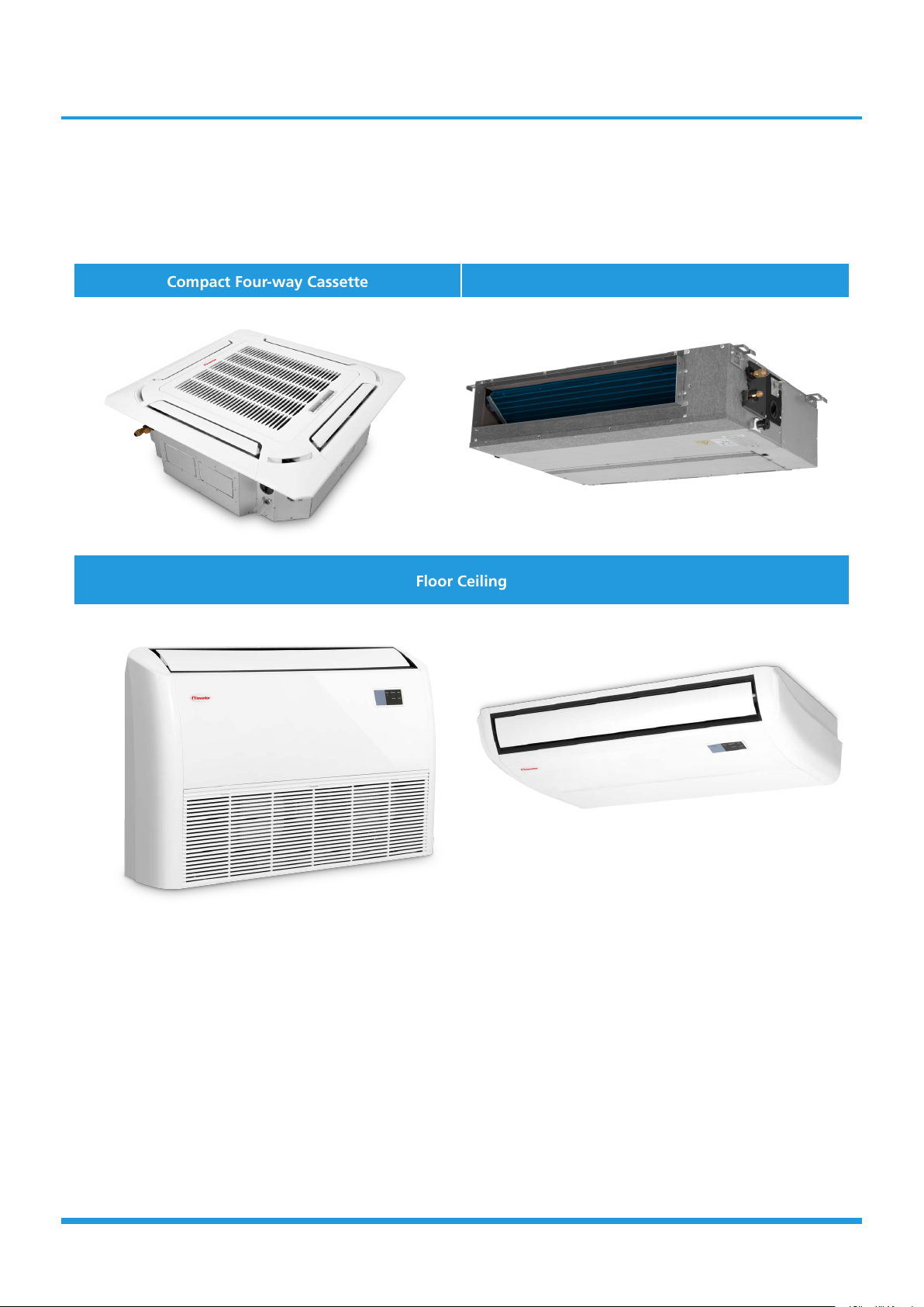
2.1 Indoor Unit
Compact Four-way Cassette A6 Duct
Floor Ceiling
Model Reference 3

2.2 Outdoor Unit
Outdoor Unit
Model Reference 4

Indoor Unit-Compact Cassette
Contents
1. Feature....................................................................................................................2
2. Dimensional Drawings ..........................................................................................4
3. Part names .............................................................................................................5
4. Service Place ...........................................................................................................6
5. Accessories .............................................................................................................7
6 Air Velocity and Temperature Distributions ........................................................8
7. Capacity Tables ....................................................................................................12
8. Noise Criterion Curves .........................................................................................18
9. Electrical Characteristics ......................................................................................20
10. Electrical Wiring Diagrams ..................................................................................20
1. Feature
1.1 Compact design
• The body size is 570×260×570mm, it’s just smaller than the ceiling board, so it’s very easy for installation and will
not damage the decoration. The panel size is 647×50×647mm.
• The hooks are designed in the four corners of the body, which can save installation space.
1.2 Fire-proof Controller Box
• Electrical control box adopts new design which can meet higher fire safety requirements.
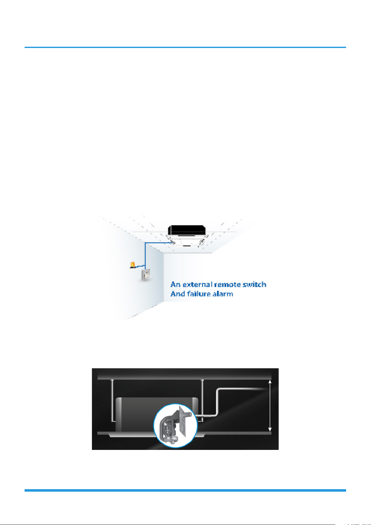
1.3 Reserved remote on-off and alarm ports(Optional for fixed-speed units, standard for
inverter units)
• Remote on-off: With the reserved ports. a remote switch can be easily connected to realize remote control.
• Alarm: The built-in PCB can output alarm signal, which achieve setting up an external alarm light or vibration gauge
possible.
1.4 Build-in Drain Pump
• The drain pump can lift the condensed water up to 750mm.
• It’s convenient to install drainage piping under most space condition.
IDU-Compact Cassette 2
up to 750mm

1.5 Fresh Air
• Fresh air intake function brings you fresh and comfortable air feeling.
1.6 Wired Controller(Optional)
• Compared with infrared remote controller, wired controller can be fixed on the wall and avoid mislaying. It's
mainly used for commercial zone and makes air conditioner control more convenient.
1.7 Louver Position Memory (Standard for ERP models)
• When you start the unit next time, the angle of horizontal louver will automatically move to the same position
as you set last time.
IDU-Compact Cassette 3
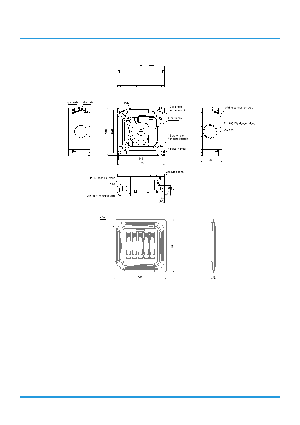
2. Dimensional Drawings
IDU-Compact Cassette 4
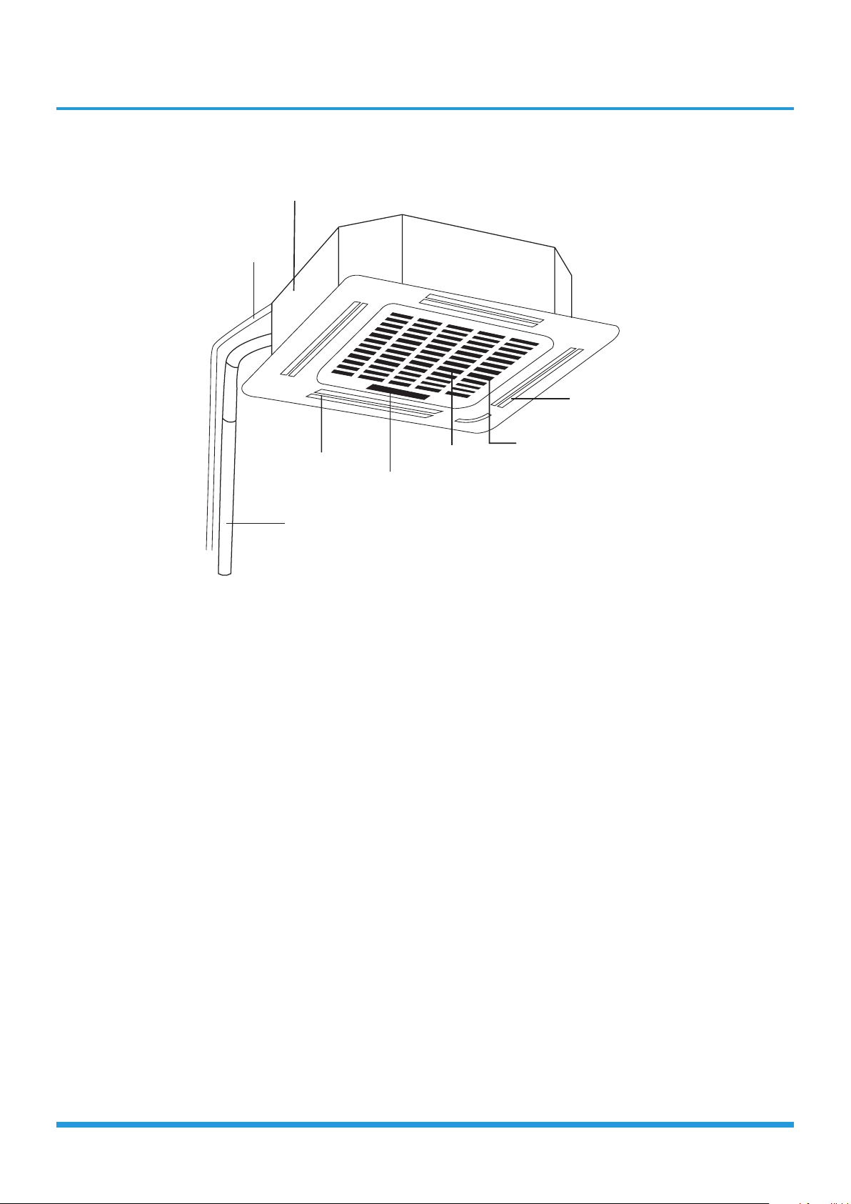
3. Part names
Drain pump
(within indoor unit)
Drain pipe
Louver
Refrigerant pipe
Air outlet
Air inlet
Front grille
Display panel
IDU-Compact Cassette 5
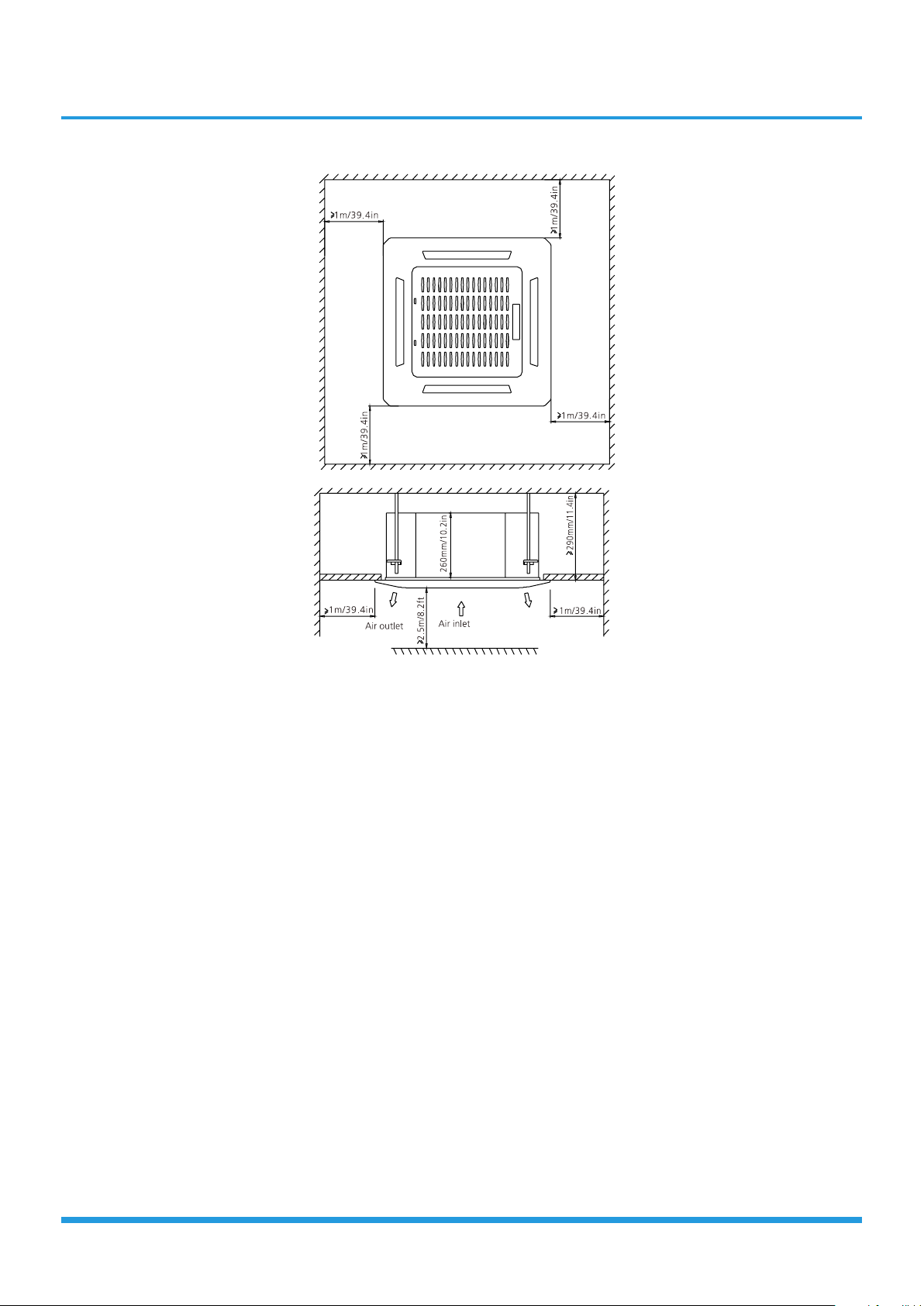
4. Service Place
IDU-Compact Cassette 6
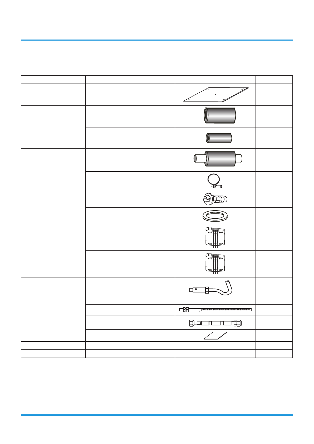
5. Accessories
The air conditioning system comes with the following accessories. Use all of the installation parts and accessories to install the air conditioner. Improper installation may result in water leakage, electrical shock and fire, or equipment failure.
Name Shape Quantity
Indoor unit installation
Refrigeration Fittings
Drainpipe Fittings
EMC Magnetic
Installation paper template (some
models)
Insulation for gas pipe fitting (some
models)
Insulation for liquid pipe fitting (some
models)
Outlet pipe sheath(some models) 1
Outlet pipe clasp(some models) 1
Drain joint (some models) 1
Seal ring (some models) 1
Magnetic ring (wrap the electric wires
S1 & S2 ( P & Q & E ) around the
magnetic ring twice)
1
1
1
1
Ring (some models)
Installation Accessory
(some models)
Optional accessories:
• There are two types of remote controls: wired and wireless.
• Select a remote controller based on customer preferences and requirements and install in an appropriate place.
• Refer to catalogues and technical literature for guidance on selecting a suitable remote controller.
Magnetic ring (Hitch it on the
connective cable between indoor unit
and outdoor unit after installation.)
Ceiling hook 4
Suspension bolt 4
Throttle (some units) 1
Anti-shock rubber 1
Owner’s manual 1
Installation manual 1
1
IDU-Compact Cassette 7
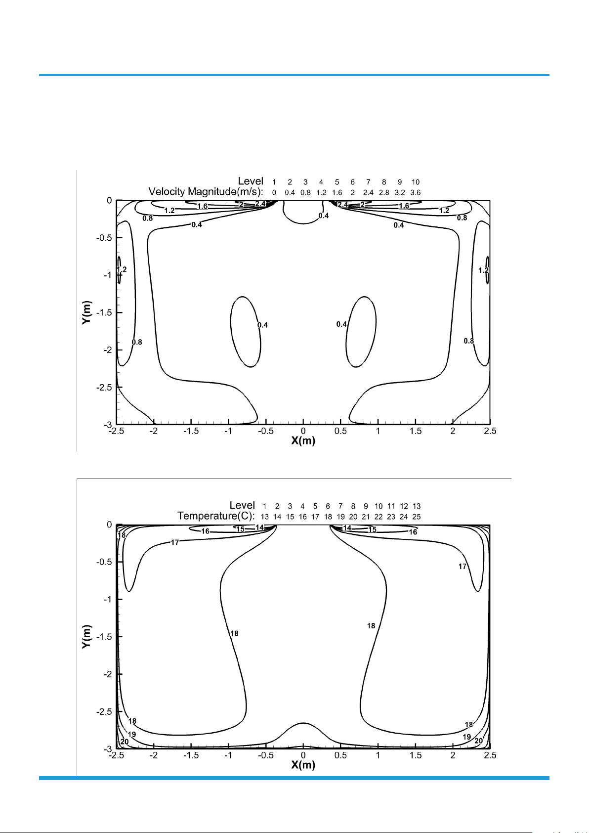
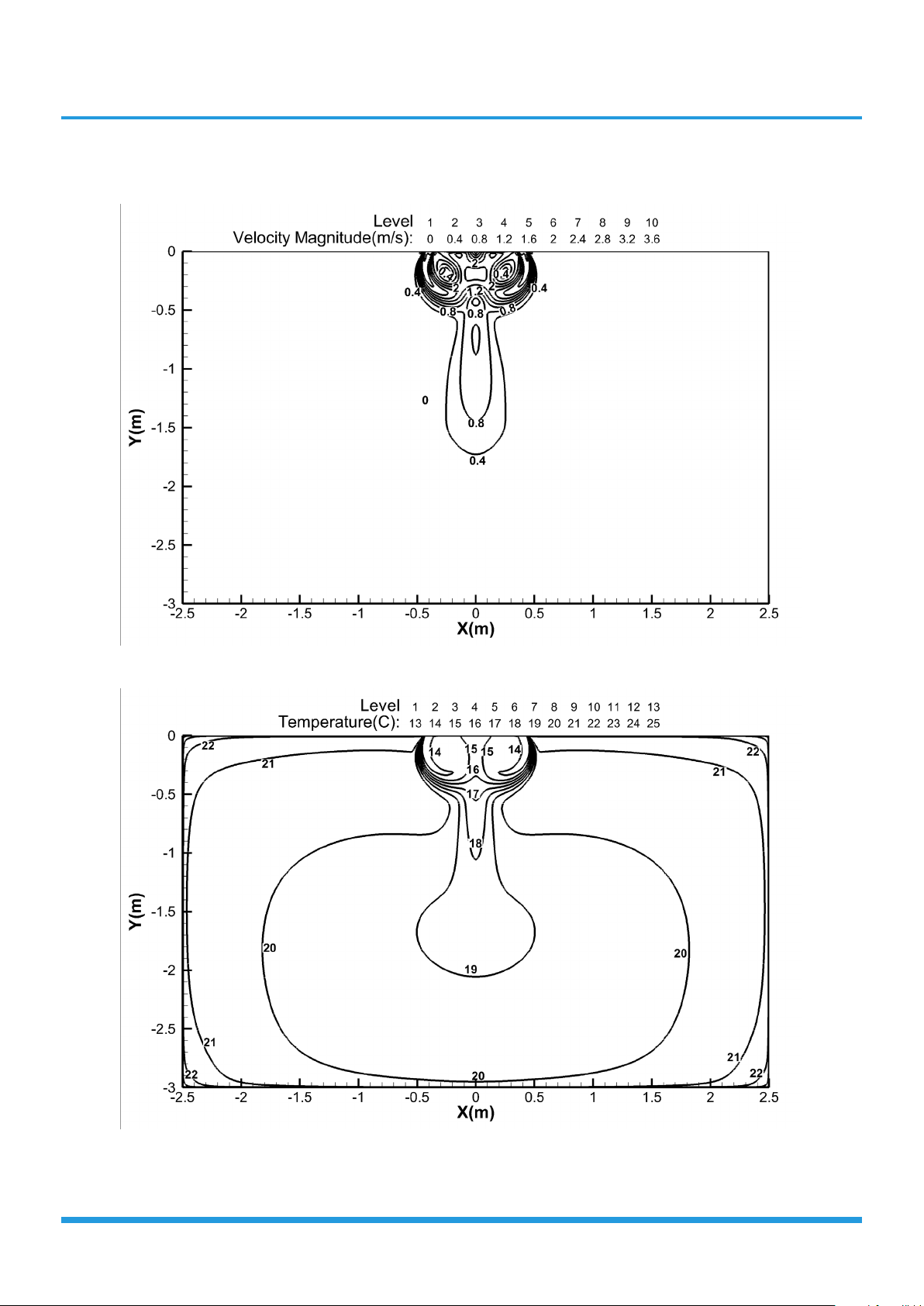
6. Air Velocity and Temperature Distributions
18K
Discharge Angle 30°
Cooling airflow velocity dis
tributions
Cooling temperature dis
tributions
IDU-Compact Cassette 8
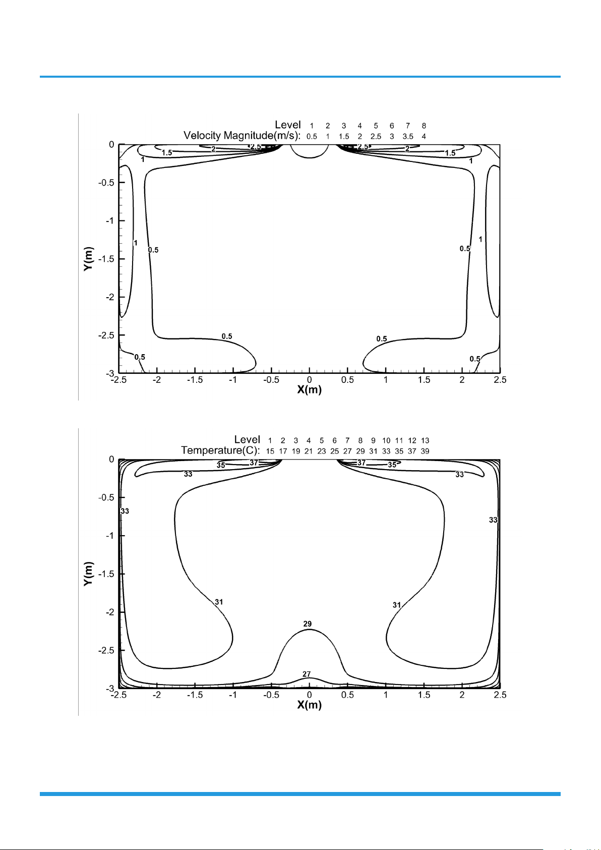
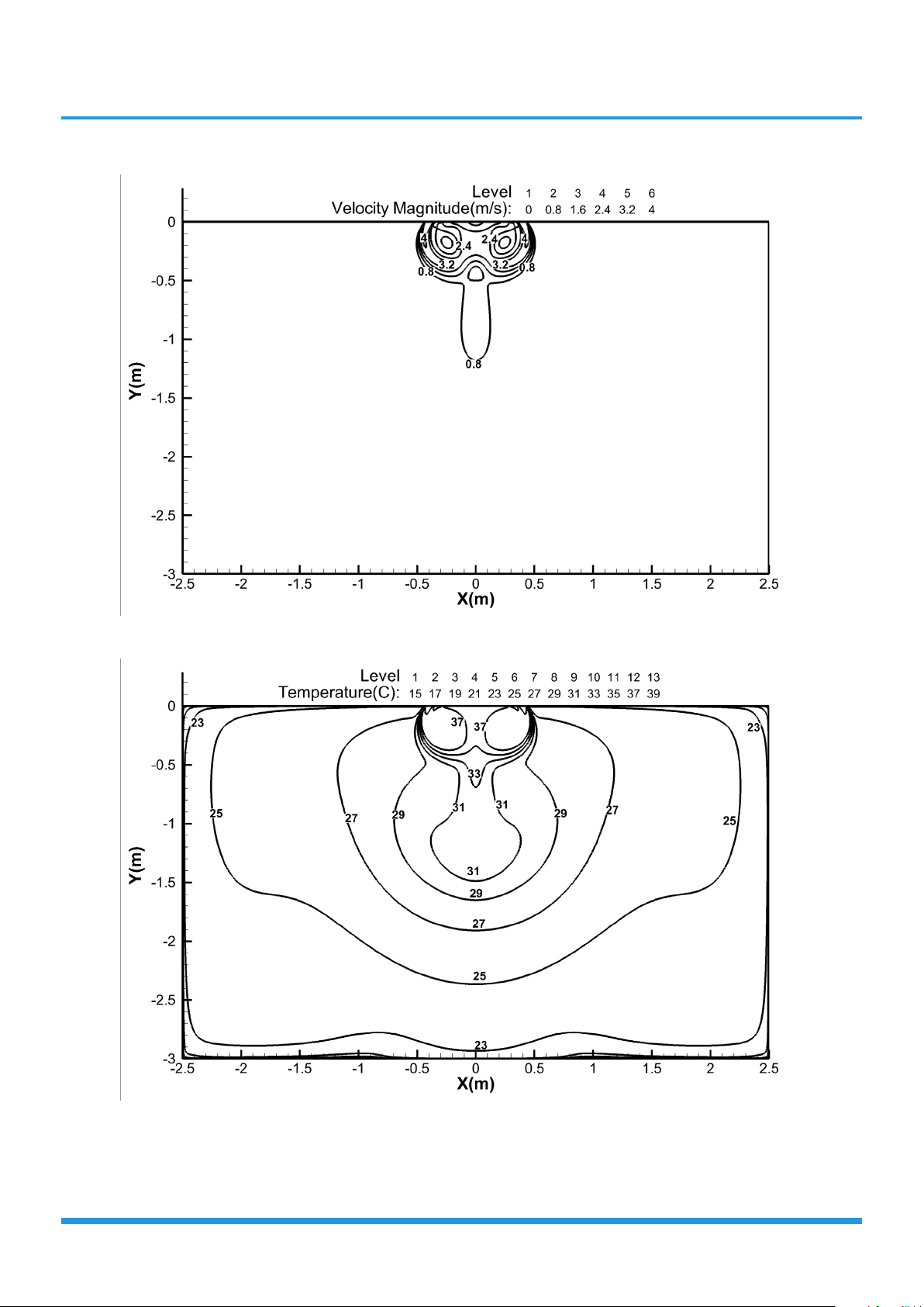
Heating airflow velocity dis
tributions
Heating temperature dis
tributions
IDU-Compact Cassette 9
Discharge Angle 60°
Cooling airflow velocity dis
tributions
Cooling temperature dis
tributions
IDU-Compact Cassette 10
Heating airflow velocity dis
tributions
Heating temperature dis
tributions
IDU-Compact Cassette 11

7. Capacity Tables
7.1 Cooling
-15
-10
ID WB
(℃)
ID DB
23.0 25.0 27.0 30.0 23.0 25.0 27.0 30.0 23.0 25.0 27.0 30.0 23.0 25.0 27.0 30.0
(℃)
TC 5.50 5.50 5.50 5.56 5.78 5.90 5.90 5.90 5.93 5.93 5.93 5.93 6.28 6.28 6.28 6.28
S/T 0.67 0.73 0.80 0.86 0.55 0.61 0.68 0.73 0.49 0.56 0.62 0.68 0.37 0.42 0.48 0.54
PI 1.09 1.08 1.08 1.09 1.08 1.08 1.08 1.08 1.09 1.09 1.09 1.09 1.08 1.08 1.08 1.08
TC 5.46 5.47 5.47 5.53 5.75 5.87 5.87 5.87 5.90 5.90 5.90 5.90 6.25 6.25 6.25 6.25
S/T 0.67 0.74 0.81 0.86 0.55 0.62 0.68 0.74 0.49 0.56 0.62 0.68 0.37 0.43 0.49 0.54
PI 1.08 1.08 1.08 1.08 1.08 1.08 1.08
-5
0
5
10
15
20
25
30
35
40
46
50
TC 5.43 5.43 5.43 5.49 5.73 5.85 5.85 5.85 5.88 5.88 5.88 5.88 6.24 6.24 6.24 6.24
S/T 0.67 0.74 0.81 0.87 0.56 0.62 0.68 0.74 0.50 0.57 0.62 0.68 0.37 0.43 0.49 0.55
PI 1.08 1.08 1.08 1.08 1.08 1.08 1.08 1.08 1.08 1.08 1.08 1.08 1.08 1.08 1.08 1.08
TC 5.40 5.41 5.41 5.47 5.71 5.83 5.83 5.83 5.87 5.87 5.87 5.87 6.23 6.23 6.23 6.23
S/T 0.68 0.74 0.81 0.87 0.56 0.62 0.69 0.74 0.50 0.57 0.63 0.69 0.37 0.43 0.49 0.55
PI 1.08 1.08 1.08 1.08 1.08 1.08 1.08 1.08 1.09 1.09 1.09 1.09 1.09 1.09 1.09 1.09
TC 5.38 5.38 5.38 5.44 5.68 5.80 5.80 5.80 5.85 5.85 5.85 5.85 6.23 6.23 6.23 6.23
S/T 0.68 0.75 0.82 0.88 0.56 0.62 0.69 0.75 0.50 0.57 0.63 0.69 0.37 0.43 0.49 0.55
PI 1.09 1.09 1.09 1.09 1.09 1.09 1.09 1.09 1.10 1.10 1.10 1.10 1.09 1.09 1.09 1.09
TC 5.34 5.35 5.35 5.41 5.66 5.78 5.78 5.78 5.82 5.82 5.82 5.82 6.21 6.21 6.21 6.21
S/T 0.68 0.75 0.82 0.88 0.56 0.63 0.69 0.75 0.50 0.57 0.63 0.69 0.38 0.44 0.50 0.55
PI 1.11 1.11 1.11 1.11 1.11 1.11 1.11 1.11 1.11 1.11 1.11 1.11 1.11 1.11 1.11 1.11
TC 5.30 5.30 5.30 5.36 5.62 5.74 5.74 5.74 5.79 5.79 5.79 5.79 6.19 6.19 6.19 6.19
S/T 0.69 0.76 0.83 0.89 0.57 0.63 0.70 0.76 0.51 0.58 0.64 0.70 0.38 0.44 0.50 0.56
PI 1.14 1.14 1.14 1.14 1.14 1.14 1.14 1.14 1.14 1.14 1.14 1.14 1.13 1.13 1.13
TC 5.24 5.24 5.24 5.30 5.56 5.56 5.56 5.56 5.73 5.73 5.73 5.73 6.13 6.13 6.13 6.13
S/T 0.69 0.76 0.83 0.89 0.57 0.63 0.70 0.76 0.51 0.58 0.64 0.70 0.38 0.44 0.50 0.56
PI 1.18 1.18 1.18 1.18 1.18 1.18 1.18 1.18 1.18 1.18 1.18 1.18 1.17 1.17 1.17 1.17
TC 4.99 4.99 4.99 5.04 5.30 5.30 5.30 5.30 5.47 5.47 5.47 5.47 5.87 5.87 5.87 5.87
S/T 0.69 0.77 0.84 0.91 0.57 0.64 0.71 0.77 0.51 0.58 0.64 0.71 0.38 0.44 0.50 0.56
PI 1.30 1.30 1.30 1.30 1.30 1.30 1.30 1.30 1.30 1.30 1.30 1.30 1.30 1.30 1.30 1.30
TC 4.76 4.76 4.76 4.81 5.07 5.07 5.07 5.07 5.22 5.22 5.22 5.22 5.62 5.62 5.62 5.62
S/T 0.70 0.78 0.85 0.92 0.57 0.64 0.71 0.79 0.51 0.58 0.65 0.72 0.37 0.44 0.50 0.57
PI 1.42 1.42 1.42 1.42 1.43 1.43 1.43 1.43 1.43 1.43 1.43 1.43 1.43 1.43 1.43 1.43
TC 4.53 4.53 4.53 4.59 4.81 4.81 4.81 4.81 4.96 4.96 5.04 4.96 5.36 5.36 5.36 5.36
S/T 0.71 0.79 0.87 0.94 0.57 0.65 0.72 0.80 0.51 0.59 0.66 0.73 0.37 0.44 0.50 0.57
PI 1.56 1.56 1.56 1.56 1.56 1.56 1.56 1.56 1.57 1.57 1.57 1.57 1.58 1.58 1.58 1.58
TC 4.28 4.28 4.29 4.34 4.55 4.55 4.55 4.55 4.70 4.70 4.74 4.70 5.07 5.07 5.07 5.07
S/T 0.72 0.81 0.89 0.98 0.58 0.66 0.75 0.83 0.51 0.59 0.67 0.75 0.36 0.44 0.51 0.58
PI 1.72 1.72 1.72 1.72 1.72 1.72 1.72 1.72 1.73 1.73 1.73 1.73 1.74 1.74 1.74 1.74
TC 3.97 3.97 4.00 4.02 4.22 4.22 4.22 4.22 4.37 4.37 4.37 4.37 4.71 4.71 4.71 4.71
S/T 0.73 0.82 0.91 1.00 0.58 0.67 0.76 0.84 0.52 0.60 0.68 0.76 0.36 0.44 0.51 0.59
PI 1.91 1.91 1.91 1.91 1.92 1.92 1.92 1.92 1.92 1.92 1.92 1.92 1.94 1.94 1.94 1.94
TC 3.71 3.71 3.74 3.77 3.97 3.97 3.97 3.97 4.11 4.11 4.11 4.11 4.45 4.45 4.45 4.45
S/T 0.74 0.84 0.94 1.00 0.59 0.68 0.77 0.86 0.52 0.61 0.69 0.78 0.36 0.44 0.52 0.60
PI 2.07 2.07 2.07 2.07 2.08 2.08 2.08 2.08 2.09 2.09 2.09 2.09 2.10 2.10 2.10 2.10
INDOOR
AIRFLOW
(CMH)
540
OUTDOOR
DB(℃)
V6MCRI32-18WiFiR+U6MRS32-18
16.0 18.0 19.0 22.0
1.08 1.08 1.08 1.08 1.08 1.08 1.08 1.08 1.08
1.13
IDU-Compact Cassette 12

-15
-10
-5
0
5
10
15
625
20
25
30
35
40
46
50
-15
-10
-5
0
5
10
15
720
20
25
30
35
40
46
50
TC 5.62 5.62 5.62 5.68 5.90 5.90 5.90 5.90 6.06 6.06 6.06 6.06 6.43 6.43 6.43 6.43
S/T 0.68 0.75 0.98 1.00 0.55 0.63 0.70 0.76 0.49 0.56 0.63 0.70 0.36 0.42 0.48 0.55
PI 1.11 1.11 1.11 1.11 1.10 1.10 1.10 1.10 1.10 1.10 1.10 1.10 1.10 1.10 1.10 1.10
TC 5.59 5.59 5.59 5.65 5.87 5.87 5.87 5.87 6.03 6.03 6.03 6.03 6.40 6.40 6.40 6.40
S/T 0.68 0.76 0.99 1.00 0.55 0.63 0.70 0.77 0.49 0.56 0.63 0.71 0.36 0.43 0.49 0.55
PI 1.10 1.10 1.10 1.10 1.10 1.10 1.10 1.10 1.10 1.10 1.10 1.10 1.11 1.11 1.11 1.11
TC 5.56 5.56 5.56 5.62 5.85 5.85 5.85 5.85 6.00 6.00 6.00 6.00 6.39 6.39 6.39 6.39
S/T 0.68 0.76 0.99 1.00 0.56 0.63 0.70 0.77 0.50 0.57 0.63 0.71 0.36 0.43 0.49 0.56
PI 1.10 1.10 1.10 1.10 1.10 1.10 1.10 1.10 1.10 1.10 1.10 1.10 1.11 1.11 1.11 1.11
TC 5.53 5.53 5.53 5.59 5.83 5.83 5.83 5.83 5.99 5.99 5.99 5.99 6.38 6.38 6.38 6.38
S/T 0.69 0.76 1.00 1.00 0.56 0.64 0.71 0.77 0.50 0.57 0.64 0.72 0.36 0.43 0.49 0.56
PI 1.11 1.11 1.11 1.11 1.10 1.10 1.10 1.10 1.10 1.10 1.10 1.10 1.11 1.11 1.11 1.11
TC 5.50 5.50 5.50 5.56 5.80 5.80 5.80 5.80 5.97 5.97 5.97 5.97 6.38 6.38 6.38 6.38
S/T 0.69 0.77 1.00 1.00 0.56 0.64 0.71 0.78 0.50 0.57 0.64 0.72 0.36 0.43 0.49 0.56
PI 1.12 1.12 1.12 1.12 1.11 1.11 1.11 1.11 1.11 1.11 1.11 1.11 1.12 1.12 1.12 1.12
TC 5.47 5.47 5.47 5.53 5.78 5.78 5.78 5.78 5.94 5.94 5.94 5.94 6.36 6.36 6.36 6.36
S/T 0.69 0.77 1.00 1.00 0.56 0.64 0.71 0.78 0.50 0.57 0.64 0.72 0.37 0.44 0.50 0.56
PI 1.13 1.13 1.13 1.13 1.13 1.13 1.13 1.13 1.13 1.13 1.13 1.13 1.13 1.13 1.13 1.13
TC 5.42 5.42 5.42 5.48 5.74 5.74 5.74 5.74 5.91 5.91 5.91 5.91 6.33 6.33 6.33 6.33
S/T 0.70 0.78 0.86 0.93 0.57 0.65 0.72 0.79 0.51 0.58 0.65 0.73 0.37 0.44 0.50 0.57
PI 1.16 1.16 1.16 1.16 1.15 1.15 1.15 1.15 1.15 1.15 1.15 1.15 1.16 1.16 1.16 1.16
TC 5.36 5.36 5.36 5.42 5.68 5.68 5.68 5.68 5.85 5.85 5.85 5.85 6.28 6.28 6.28 6.28
S/T 0.70 0.78 0.86 0.93 0.57 0.65 0.72 0.79 0.51 0.58 0.65 0.73 0.37 0.44 0.50 0.57
PI 1.20 1.20 1.20 1.20 1.19 1.19 1.19 1.19 1.19 1.19 1.19 1.19 1.19 1.19 1.19 1.19
TC 5.10 5.10 5.10 5.16 5.42 5.42 5.42 5.42 5.59 5.59 5.59 5.59 6.02 6.02 6.02 6.02
S/T 0.71 0.79 0.87 0.95 0.58 0.65 0.73 0.81 0.51 0.59 0.66 0.74 0.37 0.44 0.51 0.58
PI 1.32 1.32 1.32 1.32 1.32 1.32 1.32 1.32 1.32 1.32 1.32 1.32 1.32 1.32 1.32 1.32
TC 4.87 4.87 4.93 4.99 5.19 5.19 5.19 5.19 5.33 5.33 5.33 5.33 5.76 5.76 5.76 5.76
S/T 0.72 0.80 0.89 0.97 0.58 0.66 0.74 0.82 0.51 0.59 0.67 0.75 0.36 0.44 0.51 0.58
PI 1.45 1.45 1.45 1.45 1.46 1.46 1.46 1.46 1.46 1.46 1.46 1.46 1.46 1.46 1.46 1.46
TC 4.62 4.62 4.67 4.73 4.93 4.93 4.93 4.93 5.07 5.07 5.16 5.07 5.48 5.48 5.48 5.48
S/T 0.73 0.82 0.91 0.99 0.58 0.67 0.75 0.84 0.52 0.60 0.68 0.76 0.36 0.44 0.51 0.59
PI 1.58 1.58 1.58 1.58 1.59 1.59 1.59 1.59 1.59 1.59 1.60 1.59 1.59 1.59 1.59 1.59
TC 4.34 4.34 4.38 4.43 4.63 4.63 4.63 4.65 4.77 4.77 4.82 4.77 5.16 5.16 5.16 5.16
S/T 0.75 0.85 0.94 1.00 0.59 0.68 0.78 0.87 0.52 0.61 0.70 0.79 0.35 0.44 0.52 0.60
PI 1.74 1.74 1.74 1.74 1.75 1.75 1.75 1.75 1.75 1.75 1.76 1.75 1.76 1.76 1.76 1.76
TC 4.03 4.03 4.06 4.09 4.29 4.29 4.29 4.34 4.43 4.43 4.43 4.43 4.80 4.80 4.80 4.80
S/T 0.76 0.86 0.96 1.00 0.60 0.69 0.79 0.88 0.52 0.62 0.71 0.80 0.35 0.44 0.52 0.61
PI 1.94 1.94 1.94 1.94 1.95 1.95 1.95 1.95 1.95 1.95 1.95 1.95 1.97 1.97 1.97 1.97
TC 3.77 3.80 3.83 3.86 4.03 4.03 4.03 4.06 4.17 4.17 4.17 4.17 4.51 4.51 4.51 4.51
S/T 0.78 0.88 0.99 1.00 0.60 0.71 0.81 0.91 0.53 0.63 0.73 0.83 0.35 0.44 0.53 0.91
PI 2.11 2.11 2.11 2.11 2.11 2.11 2.11 2.11 2.12 2.12 2.12 2.12 2.14 2.14 2.14 2.14
TC 5.74 5.74 5.80 5.86 6.05 6.05 6.05 6.05 6.20 6.20 6.20 6.20 6.57 6.57 6.57 6.57
S/T 0.70 0.78 1.00 1.00 0.56 0.64 0.72 0.98 0.49 0.57 0.66 0.73 0.35 0.42 0.49 0.57
PI 1.14 1.14 1.14 1.14 1.13 1.13 1.13 1.13 1.13 1.13 1.13 1.13 1.12 1.12 1.12 1.12
TC 5.71 5.71 5.77 5.83 6.02 6.02 6.02 6.02 6.17 6.17 6.17 6.17 6.55 6.55 6.55 6.55
S/T 0.70 0.79 1.00 1.00 0.56 0.64 0.73 0.98 0.49 0.57 0.66 0.74 0.35 0.43 0.49 0.57
PI 1.13 1.13 1.13 1.13 1.12 1.12 1.12 1.12 1.13 1.13 1.13 1.13 1.12 1.12 1.12 1.12
TC 5.67 5.67 5.73 5.79 6.00 6.00 6.00 6.00 6.15 6.15 6.15 6.15 6.53 6.53 6.53 6.53
S/T 0.70 0.79 1.00 1.00 0.57 0.64 0.73 0.99 0.50 0.58 0.66 0.74 0.35 0.43 0.50 0.58
PI 1.13 1.13 1.13 1.13 1.12 1.12 1.12 1.12 1.13 1.13 1.13 1.13 1.13 1.13 1.13 1.13
TC 5.65 5.65 5.71 5.76 5.97 5.97 5.97 5.97 6.13 6.13 6.13 6.13 6.53 6.53 6.53 6.53
S/T 0.71 0.79 1.00 1.00 0.57 0.65 0.74 0.99 0.50 0.58 0.67 0.74 0.35 0.43 0.50 0.58
PI 1.13 1.13 1.13 1.13 1.13 1.13 1.13 1.13 1.13 1.13 1.13 1.13 1.13 1.13 1.13 1.13
TC 5.62 5.62 5.68 5.74 5.95 5.95 5.95 5.95 6.11 6.11 6.11 6.11 6.52 6.52 6.52 6.52
S/T 0.71 0.80 1.00 1.00 0.57 0.65 0.74 1.00 0.50 0.58 0.67 0.75 0.35 0.43 0.50 0.58
PI 1.14 1.14 1.14 1.14 1.14 1.14 1.14 1.14 1.14 1.14 1.14 1.14 1.14 1.14 1.14 1.14
TC 5.58 5.58 5.64 5.70 5.92 5.92 5.92 5.92 6.09 6.09 6.09 6.09 6.51 6.51 6.51 6.51
S/T 0.71 0.80 1.00 1.00 0.57 0.65 0.74 1.00 0.50 0.58 0.67 0.75 0.36 0.44 0.50 0.58
PI 1.16 1.16 1.16 1.16 1.15 1.15 1.15 1.15 1.16 1.16 1.16 1.16 1.15 1.15 1.15 1.15
TC 5.54 5.54 5.60 5.65 5.88 5.88 5.88 5.88 6.05 6.05 6.05 6.05 6.48 6.48 6.48 6.48
S/T 0.72 0.81 0.90 0.98 0.58 0.66 0.75 0.83 0.51 0.59 0.68 0.76 0.36 0.44 0.51 0.59
PI 1.19 1.19 1.19 1.19 1.18 1.18 1.18 1.18 1.18 1.18 1.18 1.18 1.18 1.18 1.18 1.18
TC 5.48 5.48 5.53 5.59 5.82 5.82 5.82 5.82 5.99 5.99 5.99 5.99 6.42 6.42 6.42 6.42
S/T 0.72 0.81 0.90 0.98 0.58 0.66 0.75 0.83 0.51 0.59 0.68 0.76 0.36 0.44 0.51 0.59
PI 1.23 1.23 1.23 1.23 1.22 1.22 1.22 1.22 1.22 1.22 1.22 1.22 1.21 1.21 1.21 1.21
TC 5.22 5.22 5.28 5.33 5.56 5.56 5.56 5.56 5.73 5.73 5.73 5.73 6.16 6.16 6.16 6.16
S/T 0.73 0.83 0.91 1.00 0.58 0.67 0.76 0.84 0.52 0.60 0.68 0.77 0.36 0.44 0.51 0.59
PI 1.35 1.35 1.35 1.35 1.35 1.35 1.35 1.35 1.35 1.35 1.35 1.35 1.35 1.35 1.35 1.35
TC 4.99 4.99 5.05 5.10 5.30 5.30 5.30 5.30 5.45 5.45 5.45 5.45 5.88 5.88 5.88 5.88
S/T 0.74 0.84 0.93 1.00 0.59 0.68 0.77 0.86 0.52 0.61 0.70 0.78 0.35 0.44 0.52 0.60
PI 1.49 1.49 1.49 1.49 1.49 1.49 1.49 1.49 1.49 1.49 1.49 1.49 1.50 1.50 1.50 1.50
TC 4.73 4.73 4.79 4.85 5.05 5.05 5.05 5.05 5.19 5.19 5.28 5.19 5.59 5.59 5.59 5.59
S/T 0.75 0.86 0.95 1.00 0.59 0.69 0.79 0.88 0.52 0.61 0.70 0.80 0.35 0.44 0.52 0.61
PI 1.62 1.62 1.62 1.62 1.62 1.62 1.62 1.62 1.63 1.63 1.63 1.63 1.64 1.64 1.64 1.64
TC 4.44 4.45 4.50 4.54 4.74 4.74 4.74 4.77 4.89 4.89 4.93 4.89 5.27 5.27 5.27 5.27
S/T 0.78 0.89 0.99 1.00 0.61 0.71 0.82 0.92 0.53 0.63 0.73 0.83 0.35 0.44 0.53 0.90
PI 1.79 1.79 1.79 1.79 1.79 1.79 1.79 1.79 1.80 1.80 1.80 1.80 1.81 1.81 1.81 1.81
TC 4.11 4.14 4.17 4.20 4.40 4.40 4.40 4.46 4.54 4.54 4.54 4.54 4.91 4.91 4.91 4.91
S/T 0.79 0.90 1.00 1.00 0.61 0.72 0.83 0.93 0.53 0.64 0.74 0.85 0.34 0.44 0.54 0.92
PI 1.99 1.99 1.99 1.99 1.99 1.99 1.99 1.99 2.00 2.00 2.00 2.00 2.02 2.02 2.02 2.02
TC 3.86 3.89 3.91 3.94 4.11 4.11 4.11 4.14 4.26 4.26 4.26 4.26 4.63 4.63 4.63 4.63
S/T 0.81 0.93 1.00 1.00 0.62 0.74 0.86 0.97 0.54 0.65 0.76 0.87 0.34 0.44 0.55 0.97
PI 2.15 2.15 2.15 2.15 2.16 2.16 2.16 2.16 2.17 2.17 2.17 2.17 2.19 2.19 2.19 2.19
TC:Total Cooling Capacity (kW)
S/T:Sensible Cooling Capacity Ratio
PI:Power Input(kW)
Note: The table shows the case where the operation frequency of a compressor is fixed.
IDU-Compact Cassette 13

INDOOR
AIRFLOW
(CMH)
540
625
OUTDOOR
DB(℃)
-15
-10
-5
0
5
10
15
20
25
30
35
40
46
50
-15
-10
-5
0
5
10
15
20
25
30
35
40
46
50
ID WB
(℃)
ID DB
23.0 25.0 27.0 30.0 23.0 25.0 27.0 30.0 23.0 25.0 27.0 30.0 23.0 25.0 27.0 30.0
(℃)
TC 5.50 5.50 5.50 5.56 5.78 5.90 5.90 5.90 5.93 5.93 5.93 5.93 6.28 6.28 6.28 6.28
S/T 0.67 0.73 0.80 0.86 0.55 0.61 0.68 0.73 0.49 0.56 0.62 0.68 0.37 0.42 0.48 0.54
PI 1.21 1.21 1.21 1.21 1.20 1.20 1.20 1.20 1.20 1.20 1.20 1.20 1.20 1.20 1.20 1.20
TC 5.46 5.47 5.47 5.53 5.75 5.87 5.87 5.87 5.90 5.90 5.90 5.90 6.25 6.25 6.25 6.25
S/T 0.67 0.74 0.81 0.86 0.55 0.62 0.68 0.74 0.49 0.56 0.62 0.68 0.37 0.43 0.49 0.54
PI 1.20 1.20 1.20 1.20 1.20 1.20 1.20
TC 5.43 5.43 5.43 5.49 5.73 5.85 5.85 5.85 5.88 5.88 5.88 5.88 6.24 6.24 6.24 6.24
S/T 0.67 0.74 0.81 0.87 0.56 0.62 0.68 0.74 0.50 0.57 0.62 0.68 0.37 0.43 0.49 0.55
PI 1.20 1.20 1.20 1.20 1.20 1.20 1.20 1.20 1.20 1.20 1.20 1.20 1.21 1.21 1.21 1.21
TC 5.40 5.41 5.41 5.47 5.71 5.83 5.83 5.83 5.87 5.87 5.87 5.87 6.23 6.23 6.23 6.23
S/T 0.68 0.74 0.81 0.87 0.56 0.62 0.69 0.74 0.50 0.57 0.63 0.69 0.37 0.43 0.49 0.55
PI 1.20 1.20 1.20 1.20 1.20 1.20 1.20 1.20 1.20 1.20 1.20 1.20 1.21 1.21 1.21 1.21
TC 5.38 5.38 5.38 5.44 5.68 5.80 5.80 5.80 5.85 5.85 5.85 5.85 6.23 6.23 6.23 6.23
S/T 0.68 0.75 0.82 0.88 0.56 0.62 0.69 0.75 0.50 0.57 0.63 0.69 0.37 0.43 0.49 0.55
PI 1.22 1.22 1.22 1.22 1.21 1.21 1.21 1.21 1.21 1.21 1.21 1.21 1.22 1.22 1.22 1.22
TC 5.34 5.35 5.35 5.41 5.66 5.78 5.78 5.78 5.82 5.82 5.82 5.82 6.21 6.21 6.21 6.21
S/T 0.68 0.75 0.82 0.88 0.56 0.63 0.69 0.75 0.50 0.57 0.63 0.69 0.38 0.44 0.50 0.55
PI 1.24 1.24 1.24 1.24 1.23 1.23 1.23 1.23 1.23 1.23 1.23 1.23 1.24 1.24 1.24 1.24
TC 5.30 5.30 5.30 5.36 5.62 5.74 5.74 5.74 5.79 5.79 5.79 5.79 6.19 6.19 6.19 6.19
S/T 0.69 0.76 0.83 0.89 0.57 0.63 0.70 0.76 0.51 0.58 0.64 0.70 0.38 0.44 0.50 0.56
PI 1.27 1.27 1.27 1.27 1.26 1.26 1.26 1.26 1.26 1.26 1.26 1.26 1.26 1.26 1.26 1.26
TC 5.24 5.24 5.24 5.30 5.56 5.56 5.56 5.56 5.73 5.73 5.73 5.73 6.13 6.13 6.13 6.13
S/T 0.69 0.76 0.83 0.89 0.57 0.63 0.70 0.76 0.51 0.58 0.64 0.70 0.38 0.44 0.50 0.56
PI 1.31 1.31 1.31 1.31 1.30 1.30 1.30 1.30 1.30 1.30 1.30 1.30 1.30 1.30 1.30 1.30
TC 4.99 4.99 4.99 5.04 5.30 5.30 5.30 5.30 5.47 5.47 5.47 5.47 5.87 5.87 5.87 5.87
S/T 0.69 0.77 0.84 0.91 0.57 0.64 0.71 0.77 0.51 0.58 0.64 0.71 0.38 0.44 0.50 0.56
PI 1.45 1.45 1.45 1.45 1.45 1.45 1.45 1.45 1.45 1.45 1.45 1.45 1.45 1.45 1.45 1.45
TC 4.76 4.76 4.76 4.81 5.07 5.07 5.07 5.07 5.22 5.22 5.22 5.22 5.62 5.62 5.62 5.62
S/T 0.70 0.78 0.85 0.92 0.57 0.64 0.71 0.79 0.51 0.58
PI 1.58 1.58 1.58 1.58 1.58 1.58 1.58 1.58 1.58 1.58 1.58 1.58 1.59 1.59 1.59 1.59
TC 4.53 4.53 4.53 4.59 4.81 4.81 4.81 4.81 4.96 4.96 5.04 4.96 5.36 5.36 5.36 5.36
S/T 0.71 0.79 0.87 0.94 0.57 0.65 0.72 0.80 0.51 0.59 0.66 0.73 0.37 0.44 0.50 0.57
PI 1.73 1.73 1.73 1.73 1.73 1.73 1.73 1.73 1.74 1.74 1.74 1.74 1.75 1.75 1.75 1.75
TC 4.28 4.28 4.29 4.34 4.55 4.55 4.55 4.55 4.70 4.70 4.74 4.70 5.07 5.07 5.07 5.07
S/T 0.72 0.81 0.89 0.98 0.58 0.66 0.75 0.83 0.51 0.59 0.67 0.75 0.36 0.44 0.51 0.58
PI 1.91 1.91 1.91 1.91 1.91 1.91 1.91 1.91 1.92 1.92 1.92 1.92 1.93 1.93 1.93 1.93
TC 3.97 3.97 4.00 4.02 4.22 4.22 4.22 4.22 4.37 4.37 4.37 4.37 4.71 4.71 4.71 4.71
S/T 0.73 0.82 0.91 1.00 0.58 0.67 0.76 0.84 0.52 0.60 0.68 0.76 0.36 0.44 0.51 0.59
PI 2.12 2.12 2.12 2.12 2.13 2.13 2.13 2.13 2.13 2.13 2.13 2.13 2.15 2.15 2.15 2.15
TC 3.71 3.71 3.74 3.77 3.97 3.97 3.97 3.97 4.11 4.11 4.11 4.11 4.45 4.45 4.45 4.45
S/T 0.74 0.84 0.94 1.00 0.59 0.68 0.77 0.86 0.52 0.61 0.69 0.78 0.36 0.44 0.52 0.60
PI 2.30 2.30 2.30 2.30 2.31 2.31 2.31 2.31 2.32 2.32 2.32 2.32 2.33 2.33 2.33 2.33
TC 5.62 5.62 5.62 5.68 5.90 5.90 5.90 5.90 6.06 6.06 6.06 6.06 6.43 6.43 6.43 6.43
S/T 0.68 0.75 0.98 1.00 0.55 0.63 0.70 0.76 0.49 0.56 0.63 0.70 0.36 0.42 0.48 0.55
PI 1.24 1.24 1.24 1.24 1.23 1.23 1.23 1.23 1.23 1.23 1.23 1.23 1.23 1.23 1.23 1.23
TC 5.59 5.59 5.59 5.65 5.87 5.87 5.87 5.87 6.03 6.03 6.03 6.03 6.40 6.40 6.40 6.40
S/T 0.68 0.76 0.99 1.00 0.55 0.63 0.70 0.77 0.49 0.56 0.63 0.71 0.36 0.43 0.49 0.55
PI 1.23 1.23 1.23 1.23 1.22 1.22 1.22 1.22 1.23 1.23 1.23 1.23 1.23 1.23 1.23 1.23
TC 5.56 5.56 5.56 5.62 5.85 5.85 5.85 5.85 6.00 6.00 6.00 6.00 6.39 6.39 6.39 6.39
S/T 0.68 0.76 0.99 1.00 0.56 0.63 0.70 0.77 0.50 0.57 0.63 0.71 0.36 0.43 0.49 0.56
PI 1.23 1.23 1.23 1.23 1.22 1.22 1.22 1.22 1.23 1.23 1.23 1.23 1.24 1.24 1.24 1.24
TC 5.53 5.53 5.53 5.59 5.83 5.83 5.83 5.83 5.99 5.99 5.99 5.99 6.38 6.38 6.38 6.38
S/T 0.69 0.76 1.00 1.00 0.56 0.64 0.71 0.77 0.50 0.57 0.64 0.72 0.36 0.43 0.49 0.56
PI 1.23 1.23 1.23 1.23 1.23 1.23 1.23 1.23 1.23 1.23 1.23 1.23 1.24 1.24 1.24 1.24
TC 5.50 5.50 5.50 5.56 5.80 5.80 5.80 5.80 5.97 5.97 5.97 5.97 6.38 6.38 6.38 6.38
S/T 0.69 0.77 1.00 1.00 0.56 0.64 0.71 0.78 0.50 0.57 0.64 0.72 0.36 0.43 0.49 0.56
PI 1.24 1.24 1.24 1.24 1.24 1.24 1.24 1.24 1.24 1.24 1.24 1.24 1.25 1.25 1.25 1.25
TC 5.47 5.47 5.47 5.53 5.78 5.78 5.78 5.78 5.94 5.94 5.94 5.94 6.36 6.36 6.36 6.36
S/T 0.69 0.77 1.00 1.00 0.56 0.64 0.71 0.78 0.50 0.57 0.64 0.72 0.37 0.44 0.50 0.56
PI 1.26 1.26 1.26 1.26 1.26 1.26 1.26 1.26 1.26 1.26 1.26 1.26 1.27 1.27 1.27 1.27
TC 5.42 5.42 5.42 5.48 5.74 5.74 5.74 5.74 5.91 5.91 5.91 5.91 6.33 6.33 6.33 6.33
S/T 0.70 0.78 0.86 0.93 0.57 0.65 0.72 0.79 0.51 0.58 0.65 0.73 0.37 0.44 0.50 0.57
PI 1.30 1.30 1.30 1.30 1.29 1.29 1.29 1.29 1.29 1.29 1.29 1.29 1.29 1.29 1.29 1.29
TC 5.36 5.36 5.36 5.42 5.68 5.68 5.68 5.68 5.85 5.85 5.85 5.85 6.28 6.28 6.28 6.28
S/T 0.70 0.78 0.86 0.93 0.57 0.65 0.72 0.79 0.51 0.58 0.65 0.73 0.37 0.44 0.50 0.57
PI 1.34 1.34 1.34 1.34 1.33 1.33 1.33 1.33 1.33 1.33 1.33 1.33 1.33 1.33 1.33 1.33
TC 5.10 5.10 5.10 5.16 5.42 5.42 5.42 5.42 5.59 5.59 5.59 5.59 6.02 6.02 6.02 6.02
S/T 0.71 0.79 0.87
PI 1.48 1.48 1.48 1.48 1.48 1.48 1.48 1.48 1.48 1.48 1.48 1.48 1.48 1.48 1.48 1.48
TC 4.87 4.87 4.93 4.99 5.19 5.19 5.19 5.19 5.33 5.33 5.33 5.33 5.76 5.76 5.76 5.76
S/T 0.72 0.80 0.89 0.97 0.58 0.66 0.74 0.82 0.51 0.59 0.67 0.75 0.36 0.44 0.51 0.58
PI 1.61 1.61 1.61 1.61 1.62 1.62 1.62 1.62 1.62 1.62 1.62 1.62 1.62 1.62 1.62 1.62
TC 4.62 4.62 4.67 4.73 4.93 4.93 4.93 4.93 5.07 5.07 5.16 5.07 5.48 5.48 5.48 5.48
S/T 0.73 0.82 0.91 0.99 0.58 0.67 0.75 0.84 0.52 0.60 0.68 0.76 0.36 0.44 0.51 0.59
PI 1.77 1.77 1.77 1.77 1.77 1.77 1.77 1.77 1.78 1.78 1.78 1.78 1.78 1.78 1.78 1.78
TC 4.34 4.34 4.38 4.43 4.63 4.63 4.63 4.65 4.77 4.77 4.82 4.77 5.16 5.16 5.16 5.16
S/T 0.75 0.85 0.94 1.00 0.59 0.68 0.78 0.87 0.52 0.61 0.70 0.79 0.35 0.44 0.52 0.60
PI 1.95 1.95 1.95 1.95 1.96 1.96 1.96 1.96 1.96 1.96 1.96 1.96 1.97 1.97 1.97 1.97
TC 4.03 4.03 4.06 4.09 4.29 4.29 4.29 4.34 4.43 4.43 4.43 4.43 4.80 4.80 4.80 4.80
S/T 0.76 0.86 0.96 1.00 0.60 0.69 0.79 0.88 0.52 0.62 0.71 0.80 0.35 0.44 0.52 0.61
PI 2.17 2.17 2.17 2.17 2.18 2.18 2.18 2.18 2.18 2.18 2.18 2.18 2.20 2.20 2.20 2.20
TC 3.77 3.80 3.83 3.86 4.03 4.03 4.03 4.06 4.17 4.17 4.17 4.17 4.51 4.51 4.51 4.51
S/T 0.78 0.88 0.99 1.00 0.60 0.71 0.81 0.91 0.53 0.63 0.73 0.83 0.35 0.44 0.53 0.91
PI 2.35 2.35 2.35 2.35 2.36 2.36 2.36 2.36 2.37 2.37 2.37 2.37 2.39 2.39 2.39 2.39
16.0 18.0 19.0 22.0
V6MCRI32-18WiFiR + U6MRS32-18
1.20 1.20 1.20 1.20 1.20 1.21 1.21 1.21 1.21
0.65 0.72 0.37 0.44 0.50 0.57
0.95 0.58 0.65 0.73 0.81 0.51 0.59 0.66 0.74 0.37 0.44 0.51 0.58
IDU-Compact Cassette 14

720
-15
-10
TC 5.74 5.74 5.80 5.86 6.05 6.05 6.05 6.05 6.20 6.20 6.20 6.20 6.57 6.57 6.57 6.57
S/T 0.70 0.78 1.00 1.00 0.56 0.64 0.72 0.98 0.49 0.57 0.66 0.73 0.35 0.42 0.49 0.57
PI 1.26 1.26 1.26 1.26 1.25 1.25 1.25 1.25 1.26 1.26 1.26 1.26 1.26 1.26 1.26 1.26
TC 5.71 5.71 5.77 5.83 6.02 6.02 6.02 6.02 6.17 6.17 6.17 6.17 6.55 6.55 6.55 6.55
S/T 0.70 0.79 1.00 1.00 0.56 0.64 0.73 0.98 0.49 0.57 0.66 0.74 0.35 0.43 0.49 0.57
PI 1.26 1.26 1.26 1.26 1.25 1.25 1.25 1.25 1.25 1.25 1.25 1.25 1.26 1.26 1.26 1.26
-5
0
5
10
15
20
25
30
35
40
46
50
TC 5.67 5.67 5.73 5.79 6.00 6.00 6.00 6.00 6.15 6.15 6.15 6.15 6.53 6.53 6.53 6.53
S/T 0.70 0.79 1.00 1.00 0.57 0.64 0.73 0.99 0.50 0.58 0.66 0.74 0.35 0.43 0.50 0.58
PI 1.25 1.25 1.25 1.25 1.25 1.25 1.25 1.25 1.25 1.25 1.25 1.25 1.26 1.26 1.26 1.26
TC 5.65 5.65 5.71 5.76 5.97 5.97 5.97 5.97 6.13 6.13 6.13 6.13 6.53 6.53 6.53 6.53
S/T 0.71 0.79 1.00 1.00 0.57 0.65 0.74 0.99 0.50 0.58 0.67 0.74 0.35 0.43 0.50 0.58
PI 1.26 1.26 1.26 1.26 1.25 1.25 1.25 1.25 1.26 1.26 1.26 1.26 1.27 1.27 1.27 1.27
TC 5.62 5.62 5.68 5.74 5.95 5.95 5.95 5.95 6.11 6.11 6.11 6.11 6.52 6.52 6.52 6.52
S/T 0.71 0.80 1.00 1.00 0.57 0.65 0.74 1.00 0.50 0.58 0.67 0.75 0.35 0.43 0.50 0.58
PI 1.27 1.27 1.27 1.27 1.27 1.27 1.27 1.27 1.27 1.27 1.27 1.27 1.28 1.28 1.28 1.28
TC 5.58 5.58 5.64 5.70 5.92 5.92 5.92 5.92 6.09 6.09 6.09 6.09 6.51 6.51 6.51 6.51
S/T 0.71 0.80 1.00 1.00 0.57 0.65 0.74 1.00 0.50 0.58 0.67 0.75 0.36 0.44 0.50 0.58
PI 1.29 1.29 1.29 1.29 1.29 1.29 1.29 1.29 1.29 1.29 1.29 1.29 1.29 1.29 1.29 1.29
TC 5.54 5.54 5.60 5.65 5.88 5.88 5.88 5.88 6.05 6.05 6.05 6.05 6.48 6.48 6.48 6.48
S/T 0.72 0.81 0.90 0.98 0.58 0.66 0.75 0.83 0.51 0.59 0.68 0.76 0.36 0.44 0.51 0.59
PI 1.32 1.32 1.32 1.32 1.32 1.32 1.32 1.32 1.32 1.32 1.32 1.32 1.32 1.32 1.32 1.32
TC 5.48 5.48 5.53 5.59 5.82 5.82 5.82 5.82 5.99 5.99 5.99 5.99 6.42 6.42 6.42 6.42
S/T 0.72 0.81 0.90 0.98 0.58 0.66 0.75 0.83 0.51 0.59 0.68 0.76 0.36 0.44 0.51 0.59
PI 1.37 1.37 1.37 1.37 1.36 1.36 1.36 1.36 1.36 1.36 1.36 1.36 1.36 1.36 1.36 1.36
TC 5.22 5.22 5.28 5.33 5.56 5.56 5.56 5.56 5.73 5.73 5.73 5.73 6.16 6.16 6.16 6.16
S/T 0.73 0.83 0.91 1.00 0.58 0.67 0.76 0.84 0.52 0.60 0.68 0.77 0.36 0.44 0.51 0.59
PI 1.51 1.51 1.51 1.51 1.51 1.51 1.51 1.51 1.51 1.51 1.51 1.51 1.51 1.51 1.51 1.51
TC 4.99 4.99 5.05 5.10 5.30 5.30 5.30 5.30 5.45 5.45 5.45 5.45 5.88 5.88 5.88 5.88
S/T 0.74 0.84 0.93 1.00 0.59 0.68 0.77 0.86 0.52 0.61 0.70 0.78 0.35 0.44 0.52 0.60
PI 1.65 1.65 1.65 1.65 1.65 1.65 1.65 1.65 1.65 1.65 1.65 1.65 1.66 1.66 1.66 1.66
TC 4.73 4.73 4.79 4.85 5.05 5.05 5.05 5.05 5.19 5.19 5.28 5.19 5.59 5.59 5.59 5.59
S/T 0.75 0.86 0.95 1.00 0.59 0.69 0.79 0.88 0.52 0.61 0.70 0.80 0.35 0.44 0.52 0.61
PI 1.81 1.81 1.81 1.81 1.81 1.81 1.81 1.81 1.82 1.82 1.82 1.82 1.83 1.83 1.83 1.83
TC 4.44 4.45 4.50 4.54 4.74 4.74 4.74 4.77 4.89 4.89 4.93 4.89 5.27 5.27 5.27 5.27
S/T 0.78 0.89 0.99 1.00 0.61 0.71 0.82 0.92 0.53 0.63 0.73 0.83 0.35 0.44 0.53 0.90
PI 2.00 2.00 2.00 2.00 2.00 2.00 2.00 2.00 2.01 2.01 2.01 2.01 2.02 2.02 2.02 2.02
TC 4.11 4.14 4.17 4.20 4.40 4.40 4.40 4.46 4.54 4.54 4.54 4.54 4.91 4.91 4.91 4.91
S/T 0.79 0.90 1.00 1.00 0.61 0.72 0.83 0.93 0.53 0.64 0.74 0.85 0.34 0.44 0.54 0.92
PI 2.22 2.22 2.22 2.22 2.23 2.23 2.23 2.23 2.23 2.23 2.23 2.23 2.25 2.25 2.25 2.25
TC 3.86 3.89 3.91 3.94 4.11 4.11 4.11 4.14 4.26 4.26 4.26 4.26 4.63 4.63 4.63 4.63
S/T 0.81 0.93 1.00 1.00 0.62 0.74 0.86 0.97 0.54 0.65 0.76 0.87 0.34 0.44 0.55 0.97
PI 2.40 2.40 2.40 2.40 2.42 2.42 2.42 2.42 2.42 2.42 2.42 2.42 2.44 2.44 2.44 2.44
TC:Total Cooling Capacity (kW)
S/T:Sensible Cooling Capacity Ratio
PI:Power Input(kW)
Note: The table shows the case where the operation frequency of a compressor is fixed.
IDU-Compact Cassette 15

7.2 Heating
V6MCRI32-18WiFiR + U6MRS32-18
HEATING PERFORMANCE AT INDOOR DRY BULB TEMPERATURE
INDOOR
AIRFLOW (CMH)
540
625
720
OUTDOOR
DB(°C)
-7.0 4.7 4.5 4.6 4.6 1.85 1.91 1.88 1.89
-5.6 4.6 4.6 4.5 4.5 1.80 1.82 1.83 1.84
-2.8 4.7 4.6 4.6 4.5 1.72 1.74 1.75 1.75
0.0 4.6 4.6 4.5 4.5 1.64 1.65 1.66 1.67
2.8 4.7 4.7 4.7 4.6 1.58 1.59 1.59 1.60
5.6 5.0 5.0 5.0 4.9 1.51 1.52 1.52 1.52
7.0 5.3 5.3 5.2 5.2 1.48 1.45 1.49 1.49
11.1 5.5 5.5 5.4 5.4 1.37 1.37 1.37 1.37
13.9 5.7 5.6 5.5 5.5 1.30 1.30 1.30 1.29
16.7 5.8 5.7 5.7 5.6 1.23 1.22 1.22 1.21
18.0 5.9 5.8 5.7 5.7 1.19 1.19 1.18 1.18
-7.0 4.8 4.6 4.7 4.7 1.86
-5.6 4.7 4.7 4.7 4.6 1.82 1.84 1.85 1.86
-2.8 4.7 4.7 4.7 4.7 1.74 1.75 1.76 1.77
0.0 4.7 4.7 4.6 4.6 1.66 1.67 1.67 1.68
2.8 4.9 4.8 4.8 4.7 1.59 1.60 1.60 1.61
5.6 5.2 5.1 5.1 5.0 1.52 1.53 1.53 1.53
7.0 5.5 5.4 5.3 5.3 1.49 1.46 1.50 1.50
11.1 5.7 5.6 5.5 5.5 1.38 1.38 1.38 1.38
13.9 5.8 5.7 5.7 5.6 1.31 1.31 1.30 1.30
16.7 5.9 5.8 5.8 5.7 1.24 1.23 1.22 1.22
18.0 6.0 5.9 5.9 5.8 1.20 1.19 1.19 1.18
-7.0 4.8 4.7 4.7 4.7 1.88 1.95 1.92 1.93
-5.6 4.8 4.7 4.7 4.7 1.84 1.86 1.87 1.88
-2.8 4.8 4.7 4.7 4.7 1.75 1.77 1.78 1.79
0.0 4.8 4.7 4.7 4.7 1.67 1.68 1.69 1.70
2.8 4.9 4.9 4.8
5.6 5.2 5.2 5.1 5.1 1.54 1.54 1.54 1.55
7.0 5.5 5.5 5.4 5.4 1.50 1.47 1.51 1.51
11.1 5.7 5.6 5.6 5.6 1.39 1.39 1.39 1.39
13.9 5.9 5.8 5.7 5.7 1.32 1.31 1.31 1.31
16.7 6.0 5.9 5.9 5.8 1.24 1.23 1.23 1.22
18.0 6.1 6.0 5.9 5.9 1.20 1.19 1.19 1.18
TC:TOTAL CAPACITY IN KILOWATTS (KW) PI:TOTAL POWER IN KILOWATTS (KW)
Indoor Conditions (DB °C ) Indoor Conditions (DB °C )
16.0 20.0 22.0 24.0 16.0 20.0 22.0 24.0
4.8 1.60 1.61 1.62 1.62
Note: The table shows the case where the operation frequency of a compressor is fixed.
[SI_Unit]
1.93 1.89 1.91
7.3
IDU-Compact Cassette 16
 Loading...