

INVENTOR V5MLI32-12, V5MLO32-12 Installation Manuals
CONSOLE TYPE
AIR CONDITIONING SYSTEMS
• INSTALLATION MANUAL
• ΕΓΧΕΙΡΙΔΙΟ ΕΓΚΑΤΑΣΤΑΣΗΣ
• MANUAL DE INSTALARE
ENGLISH | ΕΛΛΗΝΙΚΑ | ROMANA
MODELS:
V5MLI32-12 / V5MLO32-12
Page 2
Accessories ....................................................04
Indoor Unit Parts ........................................ 07
Indoor Unit Installation Instructions .......08
Safety Precautions ..................................... 05
Outdoor Unit Installation ......................... 12
Outdoor Unit Installation Instructions ......12
Outdoor Unit Types and Specifications ....13
Notes on Drilling Hole in Wall ....................14
Drainpipe Installation ............................... 15
Table of Contents
Installation Manual
Indoor Unit Installation
........................... 07
Installation Overview ...............................06
1
2
5
3
4
6
Page 3
Page 3
Refrigerant Piping Connection .......................17
Notes on Pipe Length and Elevation ..............17
Refrigerant Piping Connection Instructions ...18
Wiring ................................................. 20
Outdoor Unit Wiring .................. 20
Indoor Unit Wiring ..................... 21
Power Specifications ................... 22
Air Evacuation ..................................................23
Evacuation Instructions ................................ 23
Note on Adding Refrigerant ....................... 24
Test Run .............................................25
MC MC
7
8
9
10
L N
Page 4
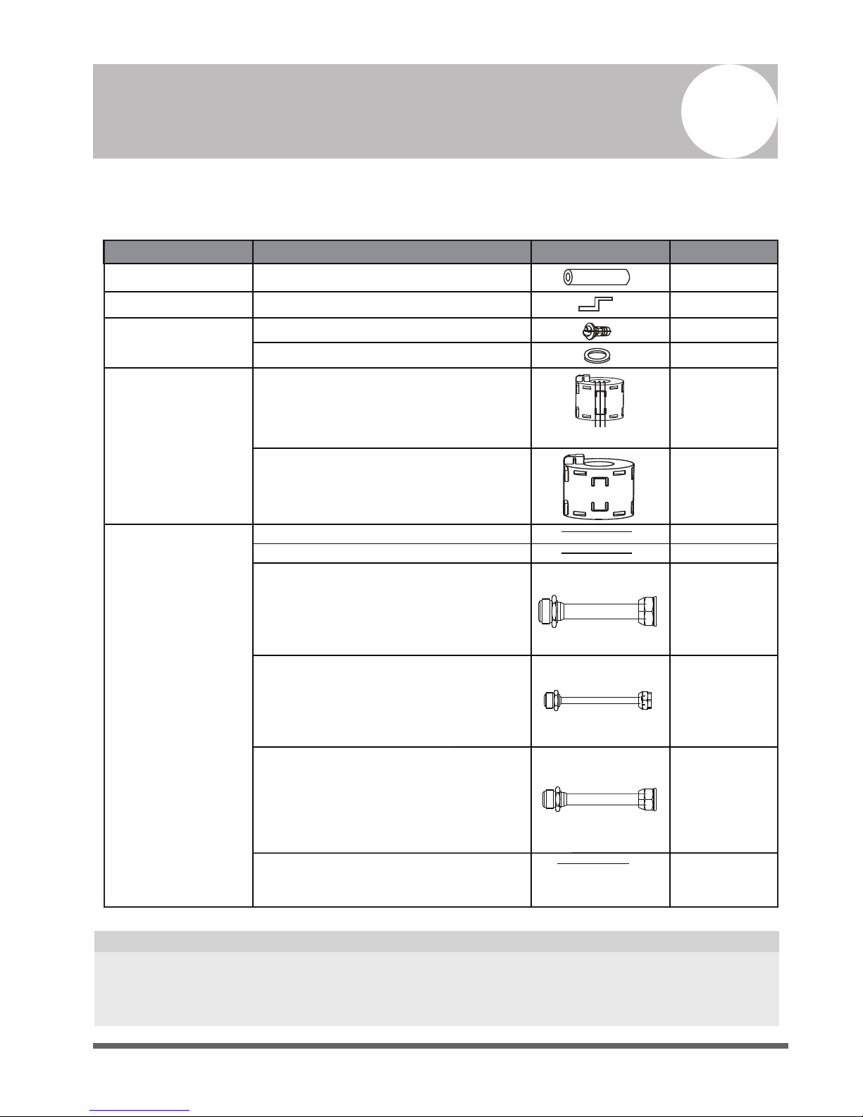
Accessories
1
The air conditioning system comes with the following accessories. Use all of the installation parts
and accessories to install the air conditioner. Improper installation may result in water leakage,
electrical shock and re, or equipment failure.
Red short connected wire
(Applied to the W/L pin of outdoor unit
terminal block be short-circuited.)
QUANTITY
SHAPENAME
Soundproof / insulation sheath (some models)
2
1
1
1
Installation Fittings
Refrigeration Fittings
Others
Installation manual
Transfer connector(Φ12.7-Φ15.9)/
( )(Packed with the indoor unit )
NOTE: Pipe size may differ from appliance to
appliance. To meet different pipe size requirements,
sometimes the pipe connections need a transfer
connector installed on the outdoor unit .
Transfer connector(Φ6.35-Φ9.52)/
( )(Packed with the indoor unit)
NOTE: Pipe size may differ from appliance to
appliance. To meet different pipe size requirements,
sometimes the pipe connections need a transfer
connector installed on the outdoor unit .
Transfer connector(Φ9.52-Φ12.7)/
( ) (Packed with the indoor unit,
used for multi-type models only )
NOTE: Pipe size may differ from appliance to
appliance. To meet different pipe size requirements,
sometimes the pipe connections need a transfer
connector installed on the outdoor unit .
1
Owner‘s manual
Drain joint (some models)
Seal ring (some models)
Drainpipe Fittings
(for cooling & heating)
Hook
EMC Magnetic Ring
Magnetic ring
(wrap the electric wires S1 & S2 ( P & Q & E )
around the magnetic ring twice)
Magnetic ring
(Hitch on the connective cable between the indoor
unit and outdoor unit after installation.)
1
1
Φ0.5in-Φ0.63in
Φ0.25in-Φ0.375in
Φ0.375in-Φ0.5in
1
(on some models)
1
(on some models)
1
(on some models)
1(on some models)
2
Optional accessories
There are two types of remote controls: wired and wireless.
Select a remote controller based on customer preferences and requirements and install in an
appropriate place.
Refer to catalogues and technical literature for guidance on selecting a suitable remote controller.
•
S1&S2(P&Q&E)
Page 5
Safety Precautions
2
Read Safety Precautions Before Installation
Incorrect installation due to ignoring instructions can cause serious damage or injury.
The seriousness of potential damage or injuries is classified as either a WARNING or CAUTION.
WARNING
• Carefully read the Safety Precautions before installation.
• In certain functional environments, such as kitchens, server rooms, etc., the use of specially
designed air-conditioning units is highly recommended.
• Only trained and certied technicians should install, repair and service this air
conditioning unit.
Improper installation may result in electrical shock, short circuit, leaks, fire or other damage to
the equipment and personal property.
• Strictly follow the installation instructions set forth in this manual.
Improper installation may result in electrical shock, short circuit, leaks, fire or other damage to
the equipment.
• Before you install the unit, consider strong winds, typhoons and earthquakes that might affect
your unit and locate it accordingly. Failure to do so could cause the equipment to fail.
• After installation, ensure there are no refrigerant leaks and that the unit is operating properly.
Refrigerant is both toxic and flammable and poses a serious health and safety risk.
Note about Fluorinated Gasses
1.
This air-conditioning unit contains fluorinated gasses. For specific information on the type of gas
and the amount, please refer to the relevant label on the unit itself.
2.
Installation, service, maintenance and repair of this unit must be performed by a certified
technician.
3.
Product uninstallation and recycling must be performed by a certified technician.
4.
If the system has a leak-detection system installed, it must be checked for leaks at least every 12
months.
5.
When the unit is checked for leaks, proper record-keeping of all checks is strongly recommended.
Failure to observe a warning may result in death. The appliance must be installed in
accordance with national regulations.
Failure to observe a caution may result in injury or equipment damage.
WARNING
CAUTION
Page 6
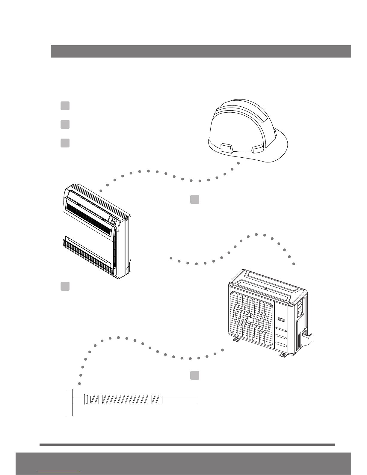
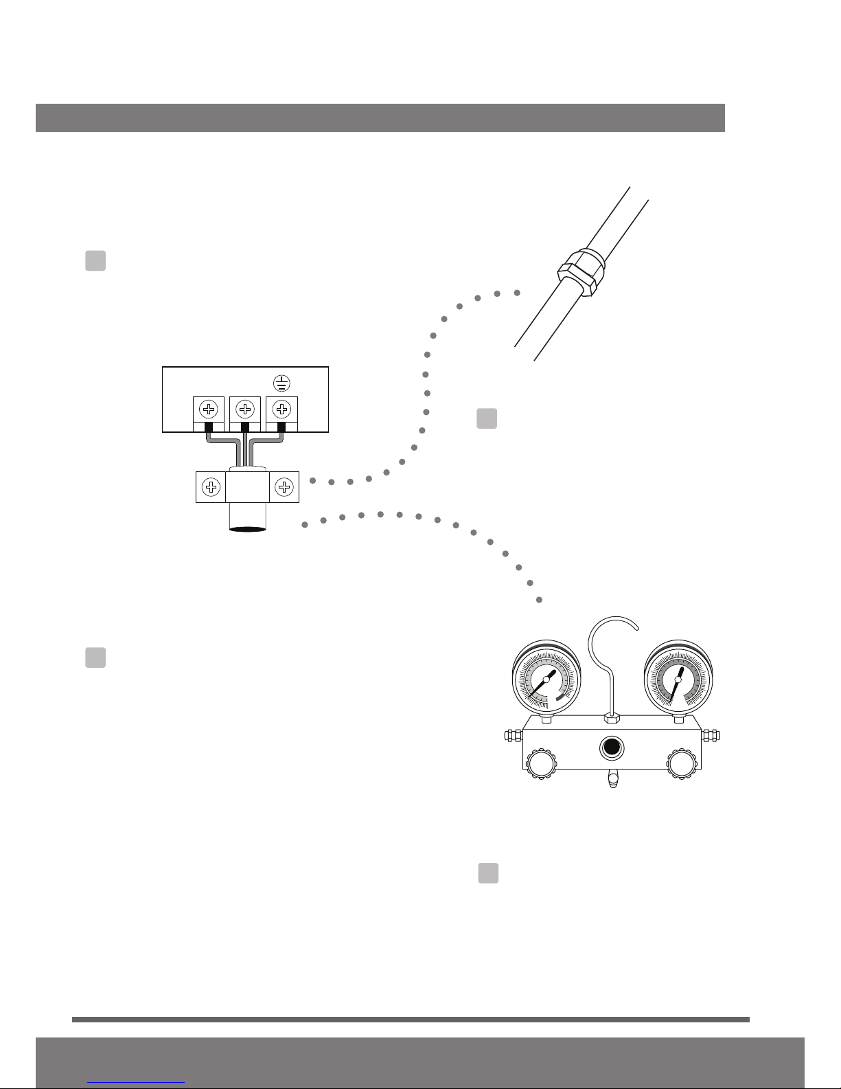
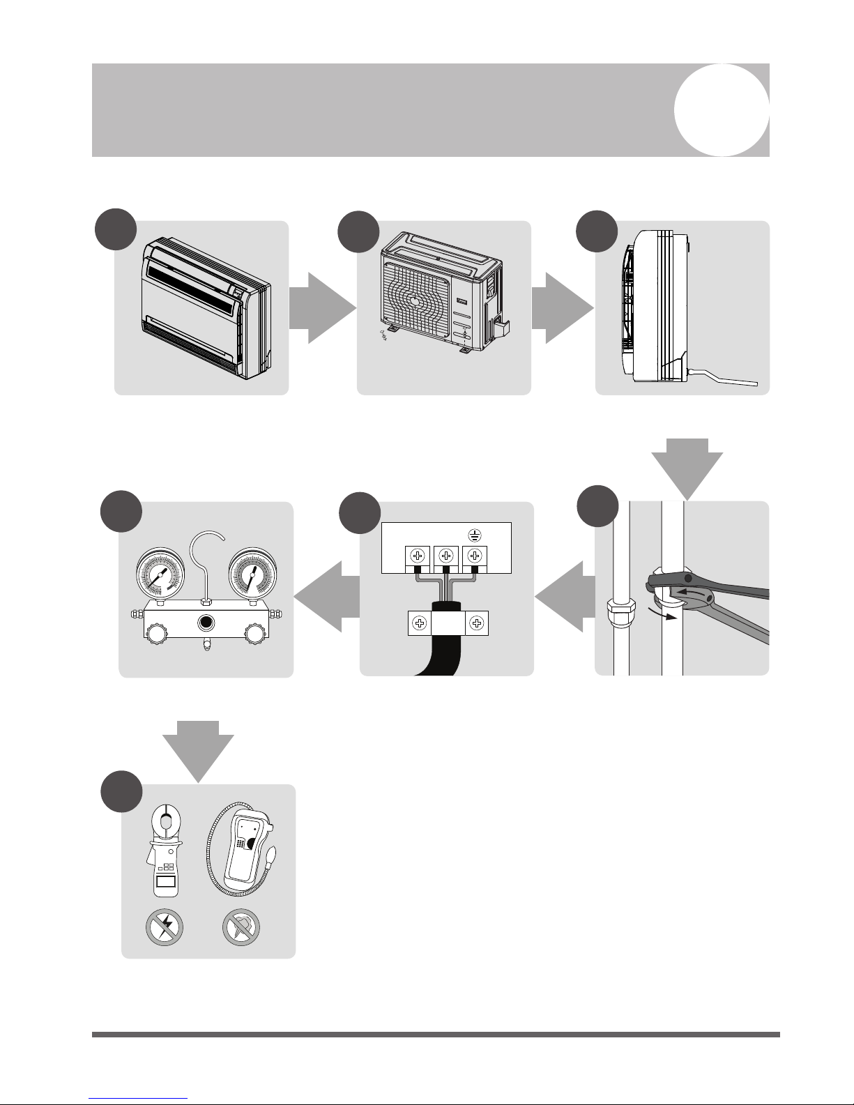
Installation Overview
3
L N
1
2
3
4
5
MC MC
6
7
Install the indoor unit
(Page 7)
INSTALLATION ORDER
Install the outdoor unit
(Page 13)
Install the drainpipe
(Page 15)
Evacuate the refrigeration system
(Page 23)
Connect the wires
(Page 20)
Connect the refrigerant pipes
(Page 17)
Perform a test run
(Page 25)
Page 7
Indoor Unit Installation
4
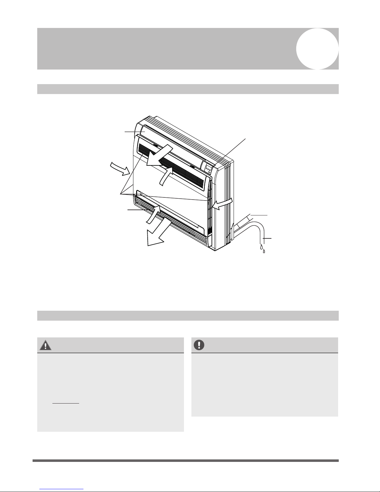
Indoor Unit Parts
Fig. 4.1
Safety Precautions
WARNING
• Securely install the indoor unit on a
structure that can sustain its weight. If the
structure is too weak, the unit may fall and
cause personal injury, unit and property
damage, or death.
• DO NOT install the indoor unit in a
bathroom or laundry room as excessive
moisture can short the unit and corrode
the wiring.
CAUTION
• Install the indoor and outdoor units, cables
and wires at least 1m (3.2’) from televisions
or radios to prevent static or image
distortion. Depending on the appliances,
a 1m (3.2’) distance may not be sufficient.
• If the indoor unit is installed on metal,
it must be electrically grounded.
Drain hose
Refrigerant connecting
pipe
Display panel
Air inlet (with air filter in it)
Air flow louver (at air outlet)
Air flow louver (at air outlet)
Page 8
Indoor Unit Installation Instructions
NOTE: Panel installation should be performed
after piping and wiring have been completed.
Step 1: Select installation location
The indoor unit should be installed in a location
that meets the following requirements:
o Enough room for installation and
maintenance.
o Enough room for the connecting pipe and
drainpipe.
o The ceiling is horizontal and its structure can
sustain the weight of the indoor unit.
o The air inlet and outlet are not impeded.
o The airflow can fill the entire room.
o There is no direct radiation from heaters.
CAUTION
DO NOT install the unit in the following
Areas with oil drilling or fracking
Coastal areas with high salt content in the
air
Areas with caustic gases in the air, such as
near hot springs
Areas with power fluctuations, such as
factories
Enclosed spaces, such as cabinets
Areas with strong electromagnetic waves
Areas that store flammable materials or gas
Rooms with high humidity, such as
bathrooms or laundry rooms
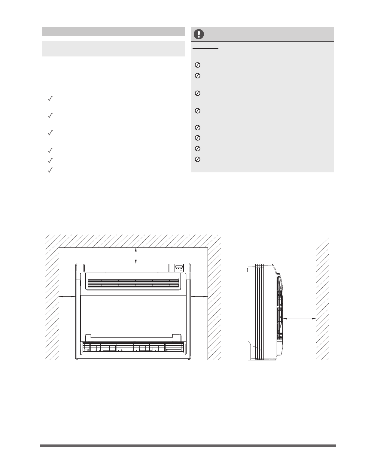
RECOMMENDED DISTANCES BETWEEN THE INDOOR UNIT
The distance between the mounted indoor unit should meet the specications illlustrated in the
following diagram. (See Fig. 4.2)
Fig. 4.2
locations:
≥100mm
≥100mm
≥100mm
≥1000mm

Page 9
Fig. 4.3
195mm
Hook
700mm
210mm
600mm
Page 10
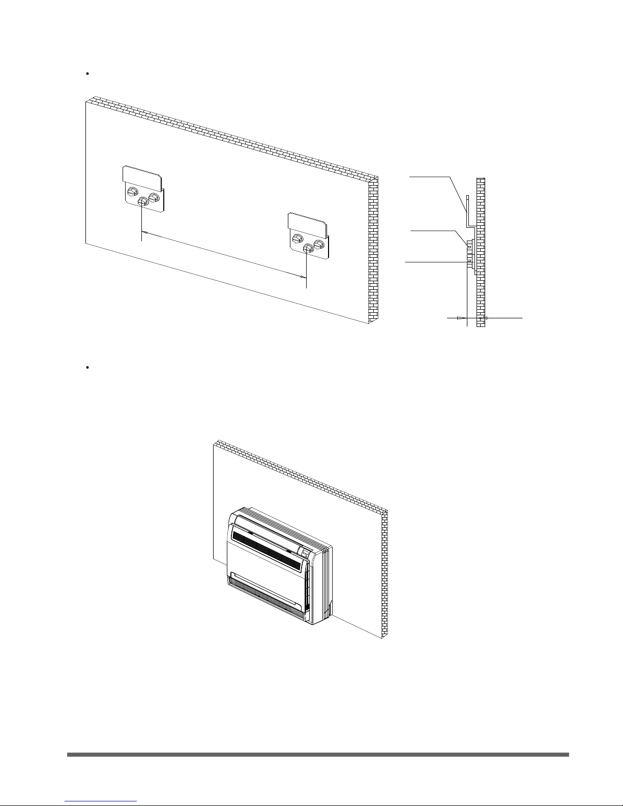
Step 2: Installing the main body
Fig. 4.4
Fig. 4.5
Afx the hook with a tapping screw onto the wall.
195mm
Hook
Tapping
screw
Washer
<6mm
Hang the indoor unit on the hook.
(The bottom of body can touch the oor or remain suspended, but the body must be installed
vertically.)
Page 11
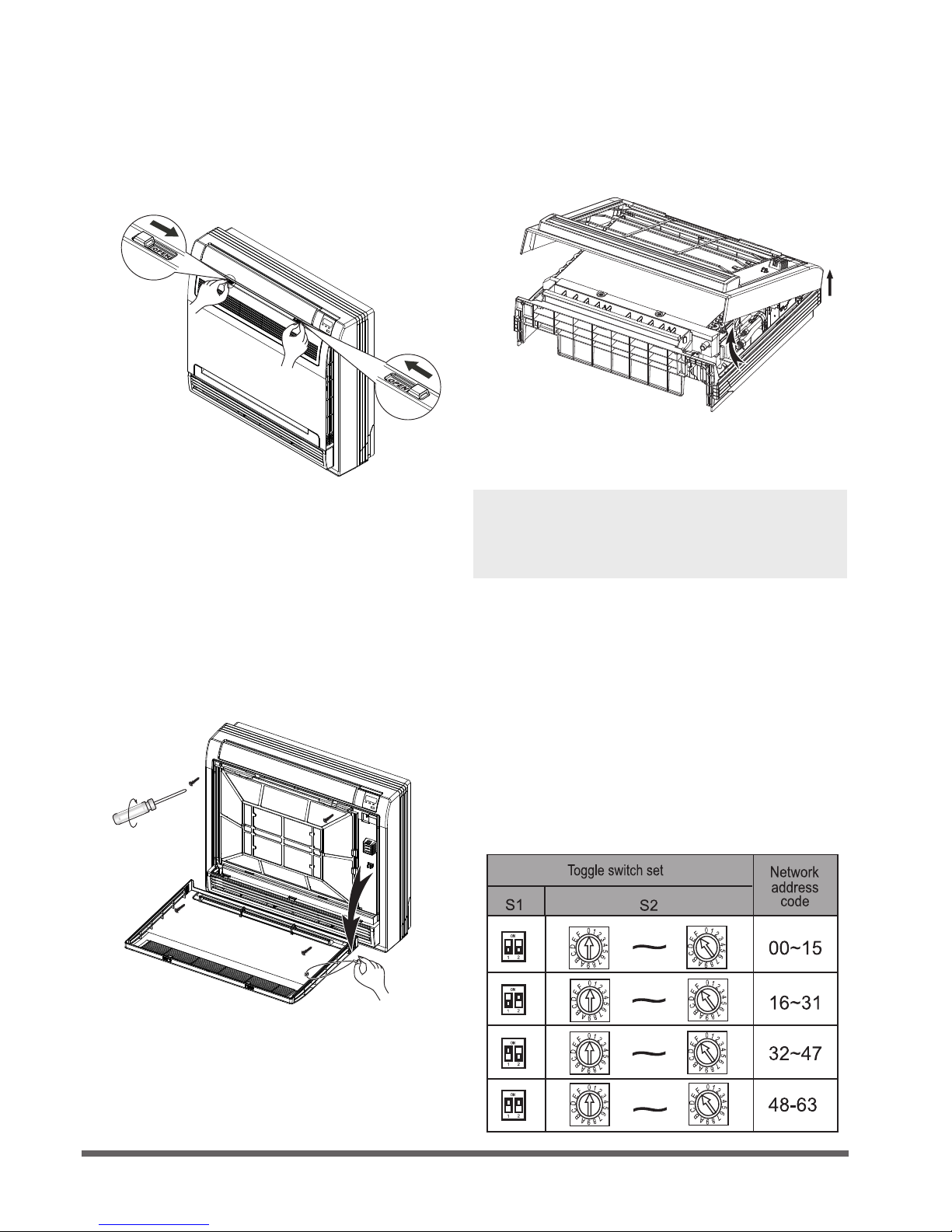
Step 3: Taking the indoor unit apart to
connect the pipes
1. Open the front panel
3. Remove the front panel.
NOTE: All the gures in this manual are for
demonstration purposes only. The air conditioner
you have purchased may be slightly different in
design, though similar in shape.
Fig. 4.6
Fig. 4.8
Fig. 4.7
Slide the two stoppers on the left and right
sides inward until they click.
3. Remove the face plate.
Remove the four screws.(See Fig.4.7)
Open the bottom of the face plate at a
30-degree angle. Lift the top of the face
plate. (See Fig.4.8)
Remove the string.
Allow the front panel to fall forward and
remove it.
Step 4: Network address set (some models)
(Only unit of 18000Btu/h has the function that
Network address set.)
Every air-conditioner in network has only one
network address to distinguish each other.
Address code of air-conditioner in LAN is set by
code switches S1 & S2 on the Main Control
Board of the indoor unit, and the set range is
0-63.
Table 4.1
Page 12
Outdoor Unit Installation
Outdoor Unit Installation Instructions
Step 1: Select installation location.
The outdoor unit should be installed in the
location that meets the following requirements:
o Place the outdoor unit as close to the indoor
unit as possible.
o Ensure that there is enough room for
installation and maintenance.
o The air inlet and outlet must not be
obstructed or exposed to strong wind.
o Ensure the location of the unit will not be
subject to snowdrifts, accumulation of leaves
or other seasonal debris. If possible, provide
an awning for the unit. Ensure the awning
does not obstruct airflow.
o
The installation area must be dry and well
ventilated.
o There must be enough room to install the
connecting pipes and cables and to access
them for maintenance.
o The area must be free of combustible gases
and chemicals.
o The pipe length between the outdoor and
indoor unit may not exceed the maximum
allowable pipe length.
o If possible, DO NOT install the unit where it
is exposed to direct sunlight.
o If possible, make sure the unit is located far
away from your neighbors’ property so that
the noise from the unit will not disturb them.
o If the location is exposed to strong winds (for
example: near a seaside), the unit must be
placed against the wall to shelter it from the
wind. If necessary, use an awning.
(See Fig. 5.1 & 5.2)
o Install the indoor and outdoor units, cables
and wires at least 1 meter from televisions or
radios to prevent static or image distortion.
Depending on the radio waves, a 1 meter
distance may not be enough to eliminate all
interference.
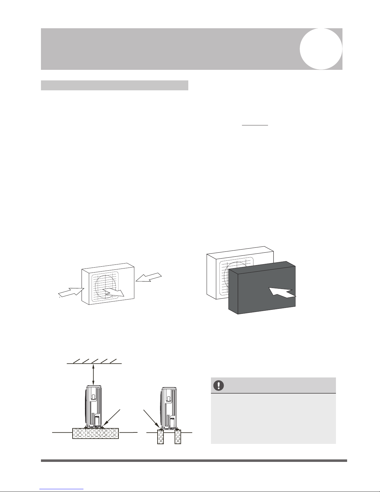
Strong wind
Strong wind
Strong wind
Fig. 5.1 Fig. 5.2
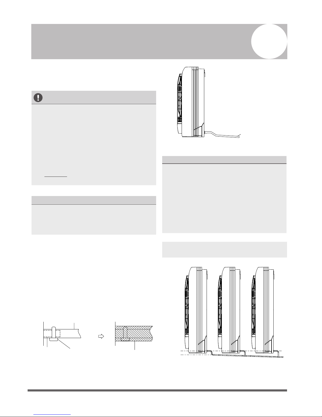
Step 2: Install outdoor unit.
Fix the outdoor unit with anchor bolts (M10)
>60cm / 23.6”
Fix with bolts
CAUTION
• Be sure to remove any obstacles that
may block air circulation.
• Make sure you refer to Length
Specifications to ensure there is
enough room for installation and
maintenance.
Fig. 5.3
5
√
√
√
√
√
√
√
√
√
√
√
√
Page 13
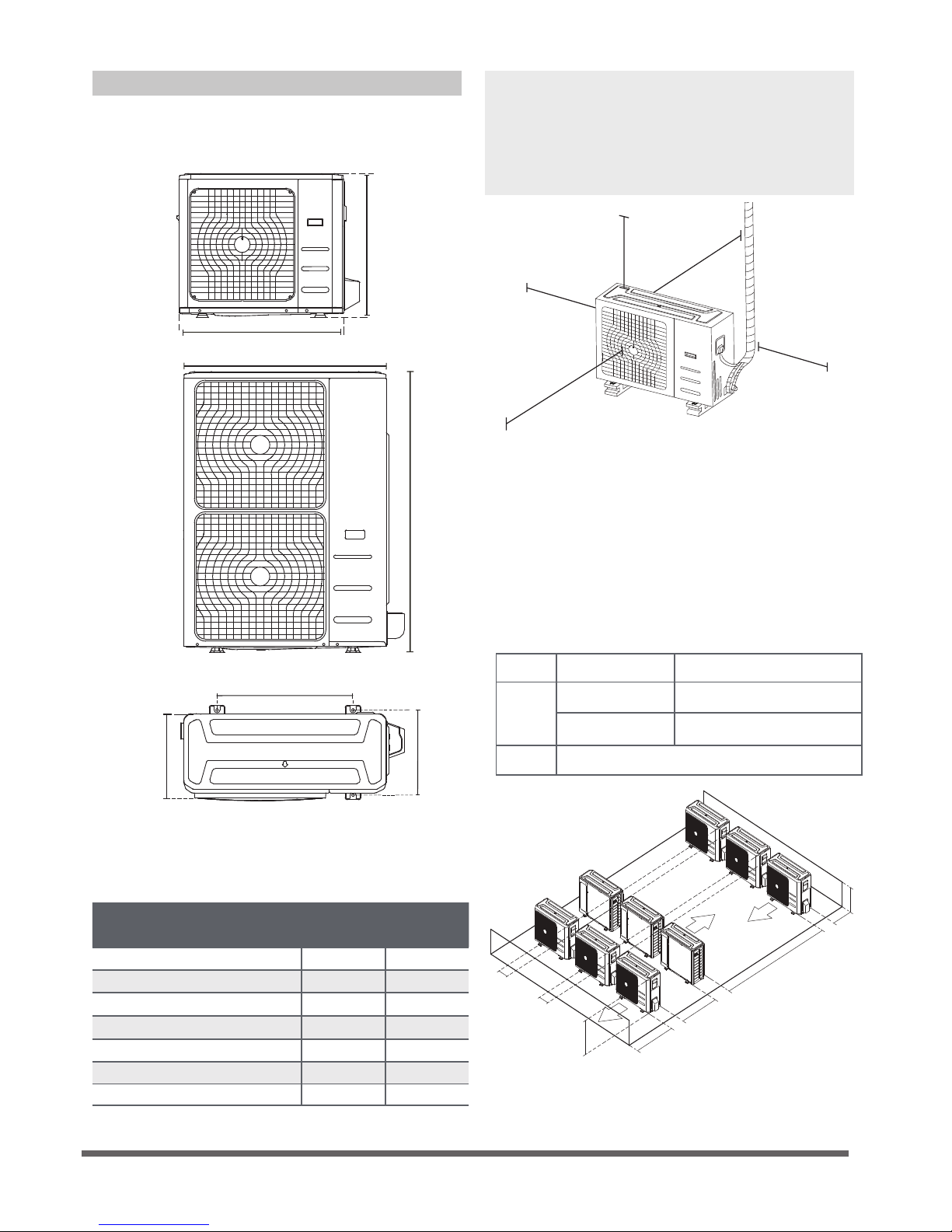
Table 5.1: Length Specications of Split
Type Outdoor Unit (unit: mm/inch)
Split Type Outdoor Unit
(Refer to Fig 5.4, 5.5, 5.6, 5.7 and Table 5.1)
Fig. 5.6
Fig. 5.5
A
B
D
W
H
W
H
Fig. 5.4
Outdoor Unit Dimensions
W x H x D
Mounting Dimensions
Distance A Distance B
760x590x285 (29.9x23.2x11.2) 530 (20.85) 290 (11.4)
780x540x250 (30.7x21.25x9.85) 549 (21.6) 276 (10.85)
810x558x310 (31.9x22x12.2) 549 (21.6) 325 (12.8)
845x700x320 (33.27x27.5x12.6) 560 (22) 335 (13.2)
845x702x363 (33.27x27.6x14.3)
540 (21.26)
350 (13.8)
770x555x300 (30.3x21.85x11.8) 487 (19.2) 298 (11.7)
800x554x333 (31.5x21.8x13.1) 514 (20.24) 340 (13.39)
Outdoor Unit Types and Specifications
NOTE: The minimum distance between the
outdoor unit and walls described in the
installation guide does not apply to airtight
rooms. Be sure to keep the unit unobstructed
in at least two of the three directions (M, N, P)
(See Fig. 5.7)
M
N
P
30 cm / 11.8” from back wall
60 cm / 23.6” on right
60 cm / 23.6” above
30 cm / 11.8” on left
200 cm / 78” in front
Fig. 5.7
Fig. 5.8
L
H
300 cm / 118” or more
A
60 cm / 23.6”
or more
150 cm / 59”
or more
25 cm / 9.8”
or more
25 cm / 9.8”
or more
Rows of series installation
L ≤ H
L ≤ 1/2H
L A
25 cm / 9.8” or more
1/2H < L ≤ H
30 cm / 11.8” or more
L > H
Can not be installed
Table 5.2 The relations between H, A and L
are as follows.
Page 14
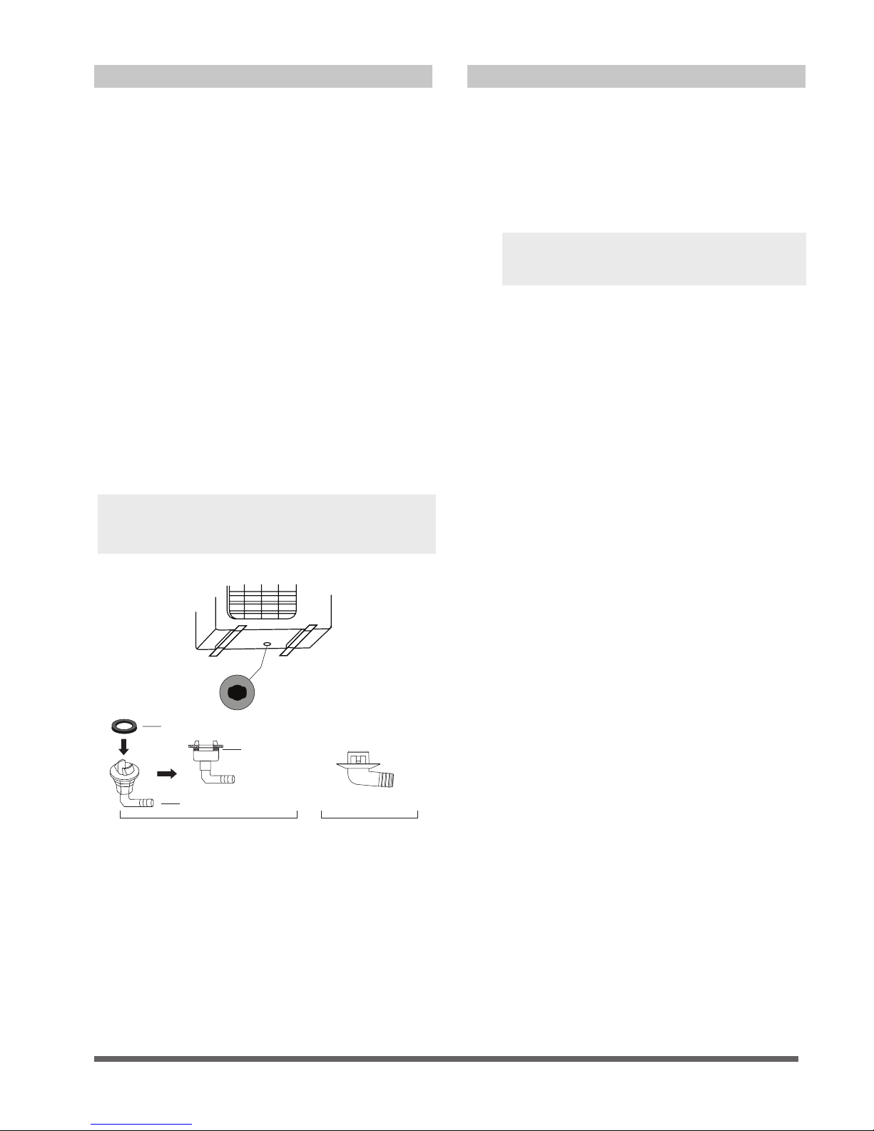
Drain Joint Installation
Seal
Drain joint
(A) (B)
Base pan hole of
outdoor unit
Seal
Fig. 5.9
Notes On Drilling Hole In Wall
You must drill a hole in the wall for the
refrigerant piping, and the signal cable that will
connect the indoor and outdoor units.
1. Determine the location of the wall hole
based on the location of the outdoor unit.
2. Using a 65-mm (2.5”) core drill, drill a hole
in the wall.
NOTE: When drilling the wall hole, make
sure to avoid wires, plumbing, and other
sensitive components.
3. Place the protective wall cuff in the hole.
This protects the edges of the hole and will
help seal it when you nish the installation
process.
If the drain joint comes with a rubber seal
(see Fig. 5.9 - A ), do the following:
1. Fit the rubber seal on the end of the drain joint
that will connect to the outdoor unit.
NOTE: Make sure the water drains to a safe
location where it will not cause water damage
or a slipping hazard.
2. Insert the drain joint into the hole in the base
pan of the unit.
3. Rotate the drain joint 90° until it clicks in place
facing the front of the unit.
4. Connect a drain hose extension (not included)
to the drain joint to redirect water from the
unit during heating mode.
If the drain joint doesn’t come with a rubber
seal (see Fig. 5.9 - B ), do the following:
1. Insert the drain joint into the hole in the base
pan of the unit. The drain joint will click in
place.
2. Connect a drain hose extension (not included)
to the drain joint to redirect water from the
unit during heating mode.
Page 15
NOTE ON DRAINPIPE INSTALLATION
•
When using an extended drainpipe, tighten
the indoor connection with an additional
protection tube. This prevents it from
pulling loose.
• The drainpipe should slope downward at a
gradient of at least 1/100 to prevent water
from flowing back into the air conditioner.
•
The drainpipe is used to drain water away from
the unit. Improper installation may cause unit
and property damage.
CAUTION
•
Insulate all piping to prevent condensation,
which could lead to water damage.
• If the drainpipe is bent or installed
incorrectly, water may leak and cause a
water-level switch malfunction.
• In HEAT mode, the outdoor unit will
discharge water. Ensure that the drain hose
is placed in an appropriate area to avoid
water damage and slippage.
• DO NOT pull the drainpipe forcefully. This
could disconnect it.
NOTE ON PURCHASING PIPES
Installation requires a polyethylene tube
(exterior diameter = 3.7-3.9cm, interior diameter
= 3.2cm), which can be obtained at your local
hardware store or dealer.
Indoor Drainpipe Installation
Install the drainpipe as illustrated in Figure 6.2.
1.
2.
Drainpipe
connecting port
Drain hose
Pipe clasp
Insulation
Fig. 6.1
Drainpipe Installation
Fig. 6.2
6
Cover the drainpipe with heat insulation to
prevent condensation and leakage.
Attach the mouth of the drain hose to the
unit’s outlet pipe. Sheath the mouth of the
hose and clip it rmly with a pipe clasp.
(See Fig 6.1)
NOTE: When connecting multiple drainpipes,
install the pipes as illustrated in Fig 6.3.
Lean over 1/100
Incorrect installation could cause water to
flow back into the unit and flood.
≥10cm
(4”)
Fig. 6.3
Page 16
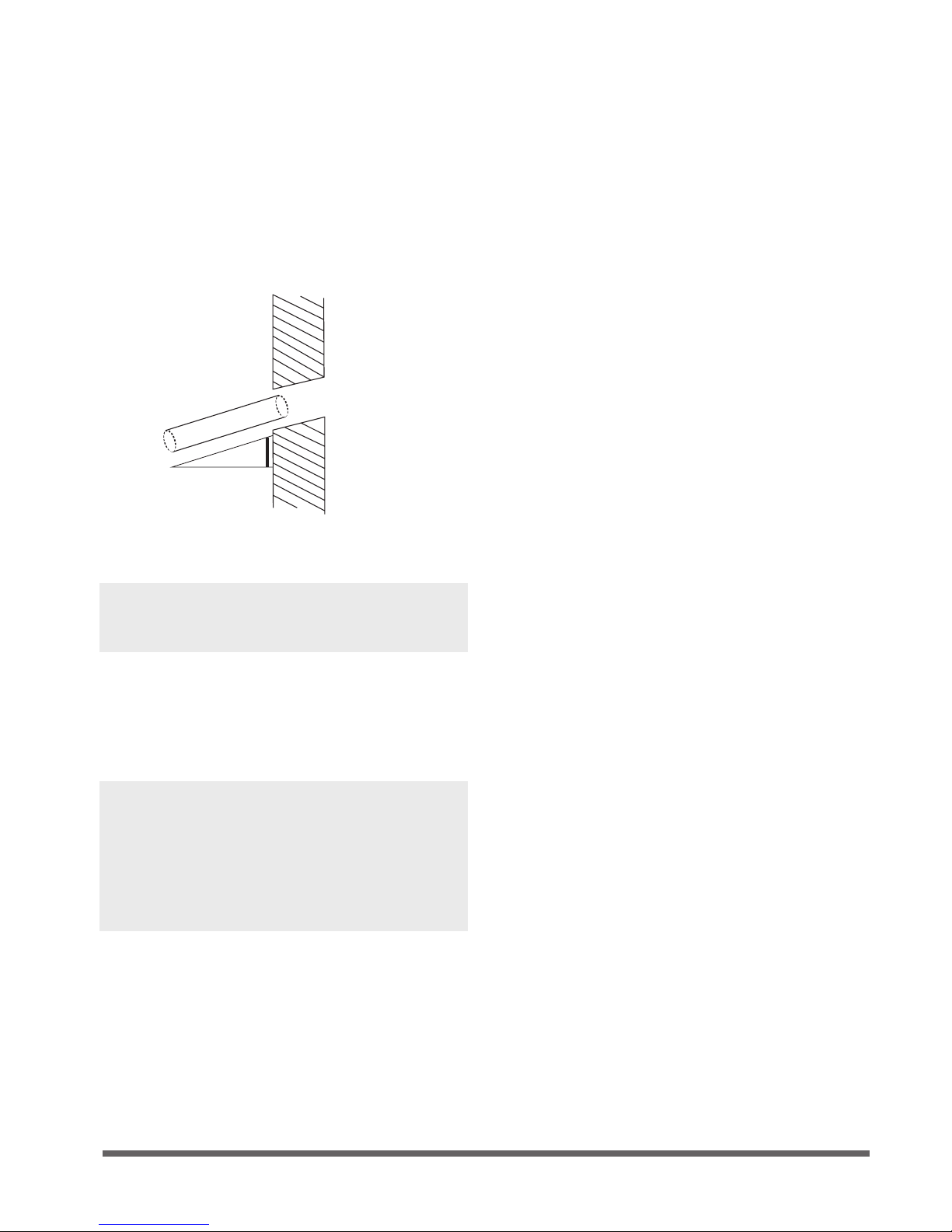
3. Using a 65-mm (2.5”) core drill, drill a hole in
the wall. Make sure that the hole is drilled at
a slight downward angle, so that the outdoor
end of the hole is lower than the indoor end
by about 12mm (0.5”). This will ensure proper
water drainage (See Fig. 6.4). Place the
protective wall cuff in the hole. This protects
the edges of the hole and will help seal it
once you nish installation.
Wall
Indoor
Outdoor
≈ 12mm / 0.5 inch
Fig. 6.4
NOTE: When drilling the hole, make sure to
avoid wires, plumbing, and other sensitive
components.
4.
Pass the drain hose through the wall hole.
Make sure the water drains to a safe location
where it will not cause water damage or a
slipping hazard.
NOTE: The drainpipe outlet should be at least
5cm (1.9”) above the ground. If it touches the
ground, the unit may become blocked and
malfunction. If you discharge the water directly
into a sewer, make sure that the drain has a U
or S pipe to catch odors that might otherwise
come back into the house.
Page 17
Refrigerant Piping Connection
Safety Precautions
WARNING
• All eld piping must be completed by a
licensed technician and must comply with
the local and national regulations.
• When the air conditioner is installed in a
small room, measures must be taken to
prevent the refrigerant concentration in
the room from exceeding the safety limit
in the event of refrigerant leakage. If the
refrigerant leaks and its concentration
exceeds its proper limit, hazards due to
lack of oxygen may result.
• When installing the refrigeration system,
ensure that air, dust, moisture or foreign
substances do not enter the refrigerant
circuit. Contamination in the system may
cause poor operating capacity, high
pressure in the refrigeration cycle,
explosion or injury.
• Ventilate the area immediately if there is
refrigerant leakage during the installation.
Leaked refrigerant gas is both toxic and
flammable. Ensure there is no refrigerant
leakage after completing the installation
work.
Notes On Pipe Length and Elevation
Ensure that the length of the refrigerant pipe, the
number of bends, and the drop height between
the indoor and outdoor units meets the
requirements shown in Table 7.1:
Table 7.1: The Maximum Length And Drop
Height Based on Models. (Unit: m/ft.)
Type of model Capacity
(Btu/h)
Length of
piping
Maximum drop
height
North America,
Australia and the
eu frequency
conversion Split
Type
<15K 25/82 10/32.8
≥15K - <24K 30/98.4 20/65.6
≥24K - <36K 50/164 25/82
≥36K - ≤60K 65/213 30/98.4
Other Split Type
12K 15/49 8/26
18K-24K 25/82 15/49
30K-36K 30/98.4 20/65.6
42K-60K 50/164 30/98.4
7
Page 18
Refrigerant Piping Connection Instructions
CAUTION
• The branching pipe must be installed
horizontally. An angle of more than 10° may
cause malfunction.
• DO NOT install the connecting pipe until
both indoor and outdoor units have been
installed.
• Insulate both the gas and liquid piping to
prevent water leakage.
Step1: Cut pipes
When preparing refrigerant pipes, take extra
care to cut and flare them properly. This will
ensure efficient operation and minimize the
need for future maintenance.
1.
Measure the distance between the indoor
and outdoor units.
2.
Using a pipe cutter, cut the pipe a little
longer than the measured distance.
CAUTION
DO NOT deform pipe while cutting. Be extra
careful not to damage, dent, or deform the pipe
while cutting. This will drastically reduce the
heating efficiency of the unit.
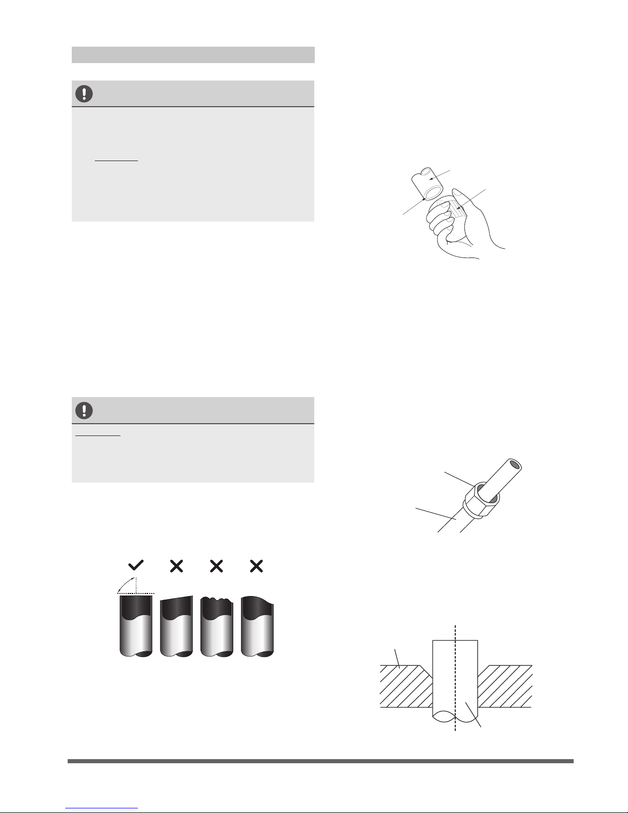
1. Make sure that the pipe is cut at a perfect
90° angle. Refer to Fig. 7.1 for examples of
bad cuts.
Oblique
Rough
Warped
90°
Fig. 7.1
Step 2: Remove burrs.
Burrs can affect the air-tight seal of refrigerant
piping connection. They must be completely
removed.
1.
Hold the pipe at a downward angle to
prevent burrs from falling into the pipe.
2. Using a reamer or deburring tool, remove
all burrs from the cut section of the pipe.
Pipe
Reamer
Point down
Fig. 7.2
Step 3: Flare pipe ends
Proper flaring is essential to achieve an airtight
seal.
1.
After removing burrs from cut pipe, seal
the ends with PVC tape to prevent foreign
materials from entering the pipe.
2. Sheath the pipe with insulating material.
3.
Place flare nuts on both ends of pipe.
Make sure they are facing in the right
direction, because you can’t put them on
or change their direction after flaring.
See Fig. 7.3
Flare nut
Copper pipe
Fig. 7.3
4. Remove PVC tape from ends of pipe when
ready to perform flaring work.
5. Clamp flare form on the end of the pipe.
The end of the pipe must extend beyond
the flare form.
Flare form
Pipe
Fig. 7.4
Page 19
6. Place flaring tool onto the form.
7. Turn the handle of the flaring tool
clockwise until the pipe is fully flared. Flare
the pipe in accordance with the dimensions
shown in table 7.2.
Table 7.2: PIPING EXTENSION BEYOND FLARE
FORM
8. Remove the flaring tool and flare form,
then inspect the end of the pipe for cracks
and even flaring.
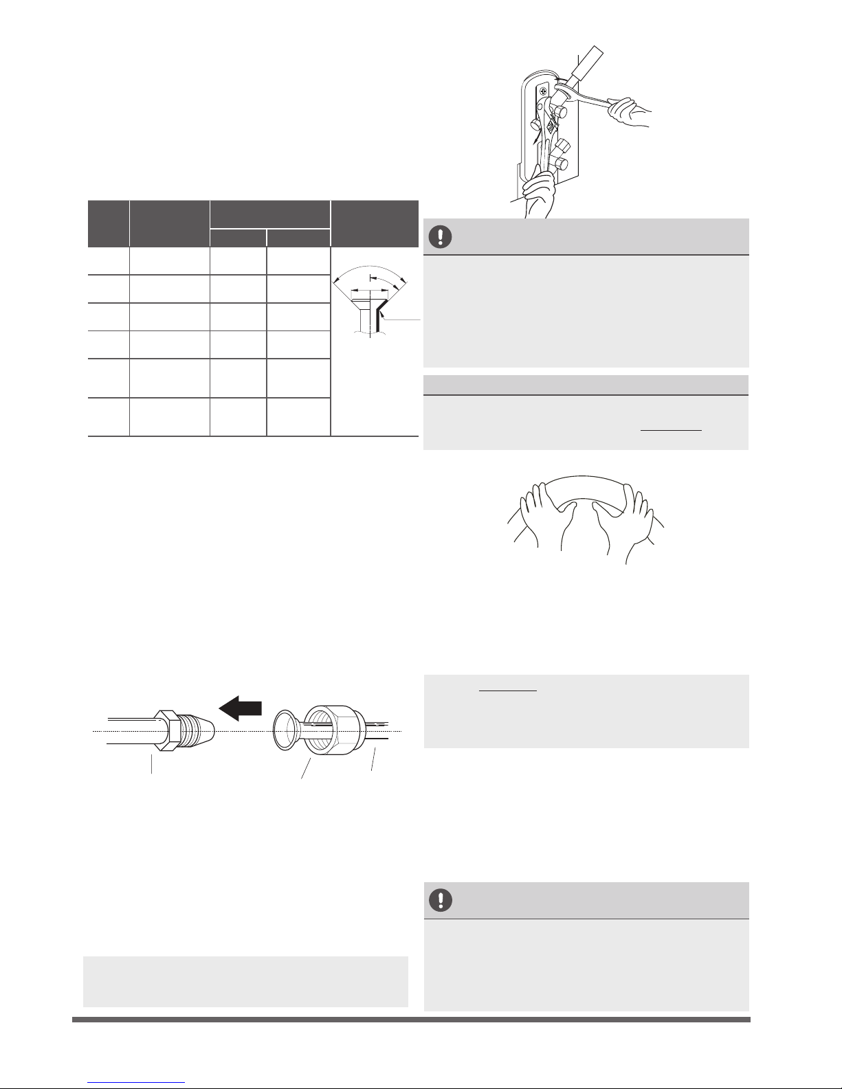
Step 4: Connect pipes
Connect the copper pipes to the indoor unit first,
then connect it to the outdoor unit. You should
first connect the low-pressure pipe, then the highpressure pipe.
1.
When connecting the flare nuts, apply a
thin coat of refrigeration oil to the flared
ends of the pipes.
2.
Align the center of the two pipes that you
will connect.
Indoor unit tubing
Flare nut
Pipe
Fig. 7.6
3.
Tighten the flare nut as tightly as possible
by hand.
4. Using a spanner, grip the nut on the unit
tubing.
5. While firmly gripping the nut, use a torque
wrench to tighten the flare nut according
to the torque values in table 7.2.
NOTE: Use both a spanner and a torque wrench
when connecting or disconnecting pipes to/from
the unit.
Fig. 7.7
CAUTION
• Ensure to wrap insulation around the piping.
Direct contact with the bare piping may result
in burns or frostbite.
•
Make sure the pipe is properly connected.
Over tightening may damage the bell mouth
and under tightening may lead to leakage.
NOTE ON MINIMUM BEND RADIUS
Carefully bend the tubing in the middle
according to the diagram below. DO NOT bend
the tubing more than 90° or more than 3 times.
Bend the pipe with thumb
min-radius 10cm (3.9”)
Fig. 7.8
6.
After connecting the copper pipes to the
indoor unit, wrap the power cable, signal
cable and the piping together with
binding tape.
NOTE: DO NOT intertwine signal cable with
other wires. While bundling these items
together, do not intertwine or cross the signal
cable with any other wiring.
7. Thread this pipeline through the wall and
connect it to the outdoor unit.
8. Insulate all the piping, including the valves
of the outdoor unit.
9. Open the stop valves of the outdoor unit
to start the flow of the refrigerant between
the indoor and outdoor unit.
CAUTION
Check to make sure there is no refrigerant leak
after completing the installation work. If there is
a refrigerant leak, ventilate the area immediately
and evacuate the system (refer to the Air
Evacuation section of this manual).
Pipe
gauge
Tightening
torque
Flare dimension (A)
(Unit: mm/Inch)
Flare shape
Min. Max.
Ø 6.4
18-20 N.m
(183-204 kgf.cm)
8.4/0.33 8.7/0.34
R0.4~0.
45
°
±
2
90
°
±
4
A
Fig. 7.6
Ø 9.5
25-26 N.m
(255-265 kgf.cm)
13.2/0.52 13.5/0.53
Ø 12.7
35-36 N.m
(357-367 kgf.cm)
16.2/0.64 16.5/0.65
Ø 15.9
45-47 N.m
(459-480 kgf.cm)
19.2/0.76 19.7/0.78
Ø 19.1
65-67 N.m
(663-683kgf.cm)
23.2/0.91 23.7/0.93
Ø 22
75-85 N.m
(765-867kgf.cm)
26.4/1.04 26.9/1.06
Page 20
TAKE NOTE OF FUSE SPECIFICATIONS
The air conditioner’s printed circuit board (PCB)
is designed with a fuse that provides overcurrent
protection. The specications of the fuse are
printed on the circuit board, examples of such
are T5A/250VAC and T10A/250VAC.
Wiring
Safety Precautions
WARNING
•
Disconnect the power supply before
working on the unit.
• All wiring must be performed according to
local and national regulations.
• Wiring must be done by a qualied
technician. Improper connections may
cause electrical malfunction, injury, or re.
• An independent circuit and single outlet
must be used for this unit.
DO NOT plug another appliance or
charger into the same outlet. If the cannot
handle the load or there is a defect in the
wiring, it can lead to shock, re, and unit
and property damage.
• Connect the power cable to the terminals
and fasten it with a clamp. An insecure
connection may cause fire.
• Make sure that all wiring is done correctly
and the control board cover is properly
installed. Failure to do so can cause
overheating at the connection points, fire,
and electrical shock.
•
Ensure that main power supply connection
is made through a switch that disconnects
all poles, with contact gap of at least 3mm
(0.118”).
• DO NOT modify the length of the power
cord or use an extension cord.
CAUTION
• Connect the outdoor wires before
connecting the indoor wires.
• Make sure you ground the unit. The
grounding wire should be located away
from gas pipes, water pipes, lightning rods,
telephone wires or other grounding wires.
Improper grounding may cause electrical
shock.
• DO NOT connect the unit to the power
source until all wiring and piping is
completed.
•
Make sure that you do not cross your
electrical wiring with your signal wiring.
This may cause distortion and interference.
To prevent distortion when the compressor starts
(you can nd the unit’s power information on
the rating sticker):
• The unit must be connected to the main
outlet. Normally, the power supply must
have a impedance of 32 ohms.
• No other equipment should be connected
to the same power circuit.
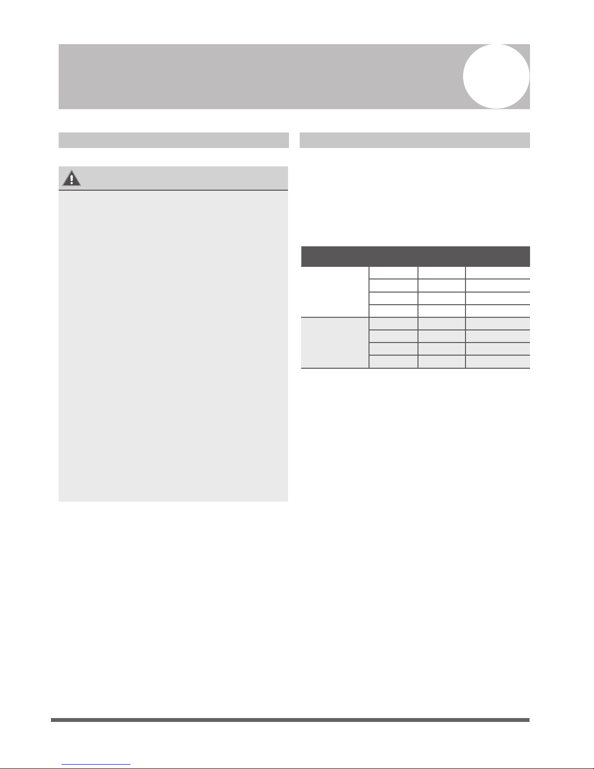
Outdoor Unit Wiring
WARNING
Before performing any electrical or wiring work,
turn off the main power to the system.
1.
Prepare the cable for connection
a.
You must first choose the right cable size.
Be sure to use H07RN-F cables.
Table 8.1: Minimum Cross-Sectional Area
of Power and Signal Cables in North
America
Rated Current of
Appliance (A)
AWG
≤ 7 18
7 - 13 16
13 - 18 14
18 - 25 12
25 - 30 10
8
Page 21
b. Using wire strippers, strip the rubber jacket
from both ends of the signal cable to reveal
approximately 15cm (5.9”) of wire.
c.
Strip the insulation from the ends.
d. Using a wire crimper, crimp u-lugs on the
ends.
NOTE: When connecting the wires, strictly
follow the wiring diagram found inside the
electrical box cover.
2. Remove the electric cover of the outdoor unit.
If there is no cover on the outdoor unit, take
off the bolts from the maintenance board and
remove the protection board.
(See Fig. 8.1)
Cover
Screw
Fig. 8.1
3. Connect the u-lugs to the terminals
Match the wire colors/labels with the labels
on the terminal block, Firmly screw the u-lug
of each wire to its corresponding terminal.
4. Clamp down the cable with the cable clamp.
5.
Insulate unused wires with electrical tape.
Keep them away from any electrical or metal
parts.
6. Reinstall the cover of the electric control box.
Indoor Unit Wiring
1.
Prepare the cable for connection
a. Using wire strippers, strip the rubber jacket
from both ends of the signal cable to reveal
about 15cm (5.9”) of the wire.
b.
Strip the insulation from the ends of the wires.
c. Using a wire crimper, crimp the u-lugs to
the ends of the wires.
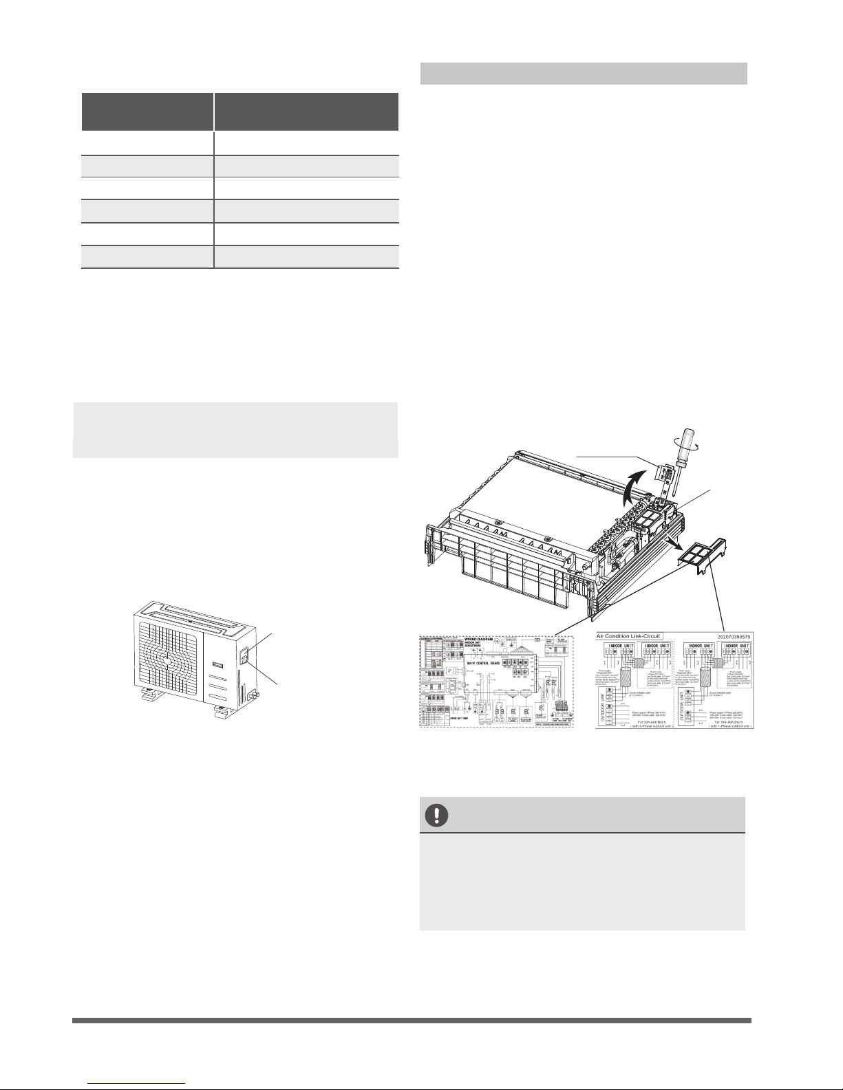
2. Rotate the sensor device’s installation bearer to
the other side. Then remove the cover of the
electrical box. (Also, remove the electrical box
also if its capacity is 18000btu/h and has
networking functionality.)
3.
Connect the u-lugs to the terminals.
Match the wire colors/labels with the labels on
the terminal block, Firmly screw the u-lug of
each wire to its corresponding terminal. Refer
to the Serial Number and Wiring Diagram
located on the cover of the electric control box.
Connective wiring diagram
Wiring diagram
Control box
CAUTION
• While connecting the wires, please strictly
follow the wiring diagram.
• The refrigerant circuit can become very
hot. Keep the interconnection cable away
from the copper tube.
4. Clamp down the cable with the cable clamp.
The cable must not be loose or pull on the
u-lugs.
5.
Reattach the electric box cover.
Fig. 8.2
Table 8.2: Other World Regions
Rated Current of
Appliance (A)
Area (mm²)
Nominal Cross-Sectional
≤ 6 0.75
6 - 10 1
10 - 16 1.5
16 - 25 2.5
25- 32 4
32 - 45 6
Installation bearer
of sensor device
Page 22
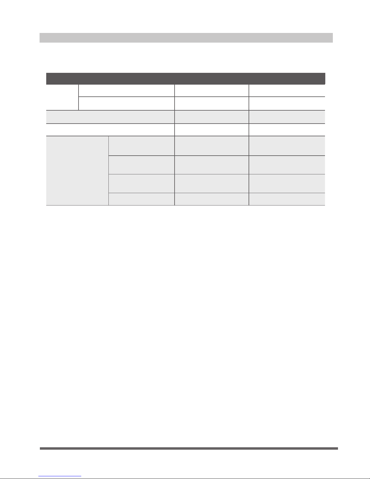
Power Specications
MODEL
(Btu/h)
<16K 16K~18K
POWER
PHASE 1 Phase 1 Phase
FREQUENCY AND VOLT
220-240V~,50Hz/60Hz 220-240V~,50Hz/60Hz
CIRCUIT BREAKER/FUSE(A)
20/16 20/16
INDOOR UNIT POWER WIRING(mm²) —— 3x1.0
OUTDOOR UNIT
POWER WIRING
GROUND WIRING
STRONG ELECTRIC
SIGNAL
WEAK ELECTRIC
SIGNAL
3x1.5 3x2.5
3x0.2
2.5
INDOOR/OUDOOR
CONNECTING
WIRING(mm²)
——
4x1.0
1.5
——
Page 23
Air Evacuation
Safety Precautions
CAUTION
• Use a vacuum pump with a gauge reading
lower than -0.1MPa and an air discharge
capacity above 40L/min.
• The outdoor unit does not need to be
vacuumed. DO NOT open the outdoor
unit’s gas and liquid stop valves.
•
Ensure that the Compound Meter reads
-0.1MPa or below after 2 hours. If after
three hours the gauge reading is still above
-0.1MPa, check if there is a gas leak or
water inside the pipe. If there is no leak,
perform another evacuation for 1 or 2 hours.
• DO NOT use refrigerant gas to evacuate the
system.
Evacuation Instructions
Before using a manifold gauge and a vacuum
pump, read their operation manuals to make
sure you know how to use them properly.
Manifold Gauge
Compound gauge
-76cmHg
Low pressure valve
High pressure valve
Charge hose
Charge hose
Vacuum pump
Pressure gauge
Low pressure valve
Fig. 9.1
1.
Connect the manifold gauge’s charge hose to
the service port on the outdoor unit’s low
pressure valve.
2. Connect the manifold gauge’s charge hose
from the to the vacuum pump.
3.
Open the Low Pressure side of the manifold
gauge. Keep the High Pressure side closed.
4.
Turn on the vacuum pump to evacuate the
system.
5.
Run the vacuum for at least 15 minutes, or
until the Compound Meter reads -76cmHG
(-1x10⁵Pa).
6.
Close the manifold gauge’s Low Pressure valve
and turn off the vacuum pump.
7.
Wait for 5 minutes, then check that there has
been no change in system pressure.
NOTE: If there is no change in system pressure,
unscrew the cap from the packed valve (high
pressure valve). If there is a change in system
pressure, there may be a gas leak.
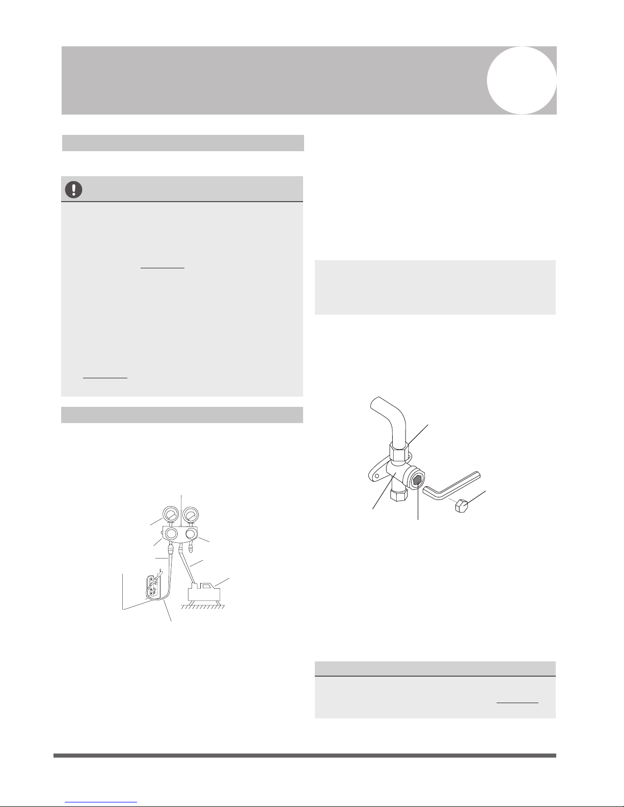
8.
Insert hexagonal wrench into the packed valve
(high pressure valve) and open the valve by
turning the wrench 1/4 counterclockwise.
Listen for gas to exit the system, then close the
valve after 5 seconds.
Flare nut
Cap
Valve body
Valve stem
Fig. 9.2
9.
Watch the Pressure Gauge for one minute to
make sure that there is no change in pressure. It
should read slightly higher than the atmospheric
pressure.
10. Remove the charge hose from the service port.
11.
Using hexagonal wrench, fully open both the
high pressure and low pressure valves.
OPEN VALVE STEMS GENTLY
When opening the valve stems, turn the hexagonal
wrench until it hits against the stopper. DO NOT
try to force the valve to open further.
12. Tighten valve caps by hand, then tighten it
using the proper tool.
9
 Loading...