

INVENTOR V4MDI-12, U4MRS-12B, V4MCRI-18, V4MDI-18UR, V4MDI-12B Service Manual
...
AIR CONDITIONING SYSTEMS
• SERVICE MANUAL
LCAC
ENGLISH

Contents
Part 1 General Information .................................................................................................... 1
Part 2 Indoor Units ................................................................................................................. 7
Part 3 Outdoor Units .......................................................................................................... 119
Part 4 Installation ............................................................................................................... 132
Part 5 Electrical Control System ....................................................................................... 171
MODELS:
U4MRS-12/V4MDI-12, U4MRS-12B/V4MDI-12B,
U4MRS-18/V4MCRI-18, U4MRS-18/V4MDI-18UR,
U4MRS-24/V4MCI-24UR, U4MRS-24/V4MKI-24UR,
U4MRS-24/V4MDI-24UR, U4MRS-36/V4MCI-36UR,
U4MRS-36/V4MKI-36UR, U4MRS-36/V4MDI-36UR,
U4MRT-42/V4MCI-42, U4MRT-42/V4MDI-42,
U4MRT-50/V4MCI-50UR, U4MRT-50/V4MDI-50,
U4MRT-60/V4MCI-60UR, U4MRT-60/V4MDI-60,
V4MFO-50/V4MFI-50, V4MFO-66B/V4MFI-66B
The specifications, designs, and information in this book are subject to change without notice for
※
product improvement.
Contents i

General Information
Part 1
General Information
1. Model Lists ........................................................................................... 2
2. External Appearance ........................................................................... 4
2.1 Indoor Units ............................................................................................................... 4
2.2 Outdoor Units ............................................................................................................ 5
General Information 1
1. Model Lists
Type
Function
12
16
18
24
30
36
42
48
55
Super slim cassette
Cooling and heating
●
● ● ● ● ● ● A5 Duct
Cooling and heating
● ● ● ● ● ● ●
●
A6 Duct
Cooling and heating
● ● ● ● ● ● ● ● Ceiling-floor
Cooling and heating
●
● ● ● ● ●
●
Four-way
cassette(compact)
Cooling and heating
●
●
Console
Cooling and heating
●
●
Cooling and heating
● ● ●
●
Cooling and heating
●
1.1 Indoor Units
R410A (capacity multiplied by 1000Btu/h)
Floor-standing
Floor-standing
1.2 Outdoor Units
Universal Outdoor unit Model Compressor type Compressor Brand Matched indoor units
Model Lists
Rotary GMCC
U4MRS-12B Rotary GMCC
U4MRS-18
U4MRS-24
U4MRS-36
U4MRT-42
U4MRT-50
U4MRT-60
V4MFO-50
Rotary GMCC
Rotary GMCC
Rotary GMCC
Rotary GMCC
Rotary GMCC
Rotary GMCC
Rotary GMCC
V4MDI-12
V4MDI-12B
V4MCRI-18
V4MDI-18UR
V4MCI-24UR
V4MKI-24UR
V4MDI-24UR
V4MCI-36UR
V4MKI-36UR
V4MDI-36UR
V4MCI-42
V4MDI-42
V4MCI-50UR
V4MDI-50
V4MCI-60UR
V4MDI-60
V4MFI-50
General Information 2
V4MFO-66B
Rotary GMCC
V4MFI-6
6B

Model Lists
General Information 3
2. External Appearance
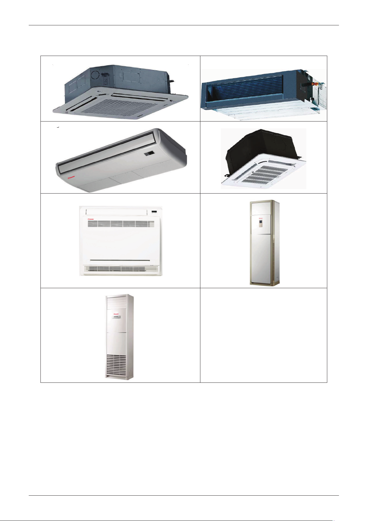
2.1 Indoor Units
External Appearance
Super slim cassette
Ceiling-Floor Compact Four-way cassette
Console Floor-standing
Duct
Floor-standing
General Information 4

2.2 Outdoor Units
Single fan outdoor unit
Double fan outdoor unit
External Appearance
General Information 5


Indoor Units
Part 2
Indoor Units
Super Slim Cassette Type ................................................... 8
A5 Duct Type ...................................................................... 23
A6 Duct Type ...................................................................... 39
Ceiling & Floor Type .......................................................... 57
Four-way Cassette Type (Compact) ................................. 73
Console Type ..................................................................... 83
Floor-standing Type .......................................................... 96
Floor-standing Type ....................................................... 108
Indoor Units 7

Super Slim Cassette Type
Super Slim Cassette Type
1. Features ........................................................................... 9
2. Dimensions .................................................................... 12
3. Service Space ................................................................ 13
4. Wiring Diagrams ............................................................ 14
5. Air Velocity Distributions (Reference Data) ................. 15
6. Electric Characteristics ................................................. 18
7. Sound Levels ................................................................. 19
8. Accessories .................................................................... 20
9. The Specification of Power ........................................... 21
10. Field Wiring .................................................................. 22
Indoor Units 8
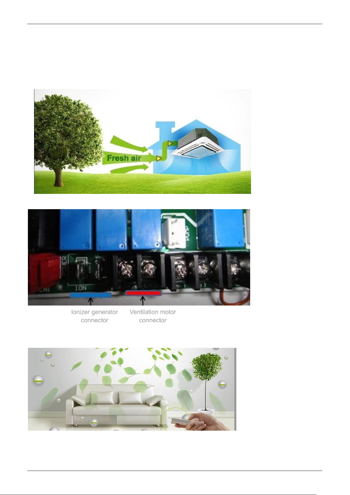
Features
Ionizer generator
connector
Ventilation motor
connector
1. Features
1.1 Overview
Compact design, super slim body size, less space requiring in installation
Each louver can be separately controlled, more comfort air blowing is possible.
Auto-lifting panel design, more convenient to clean and maintain the filter. (optional)
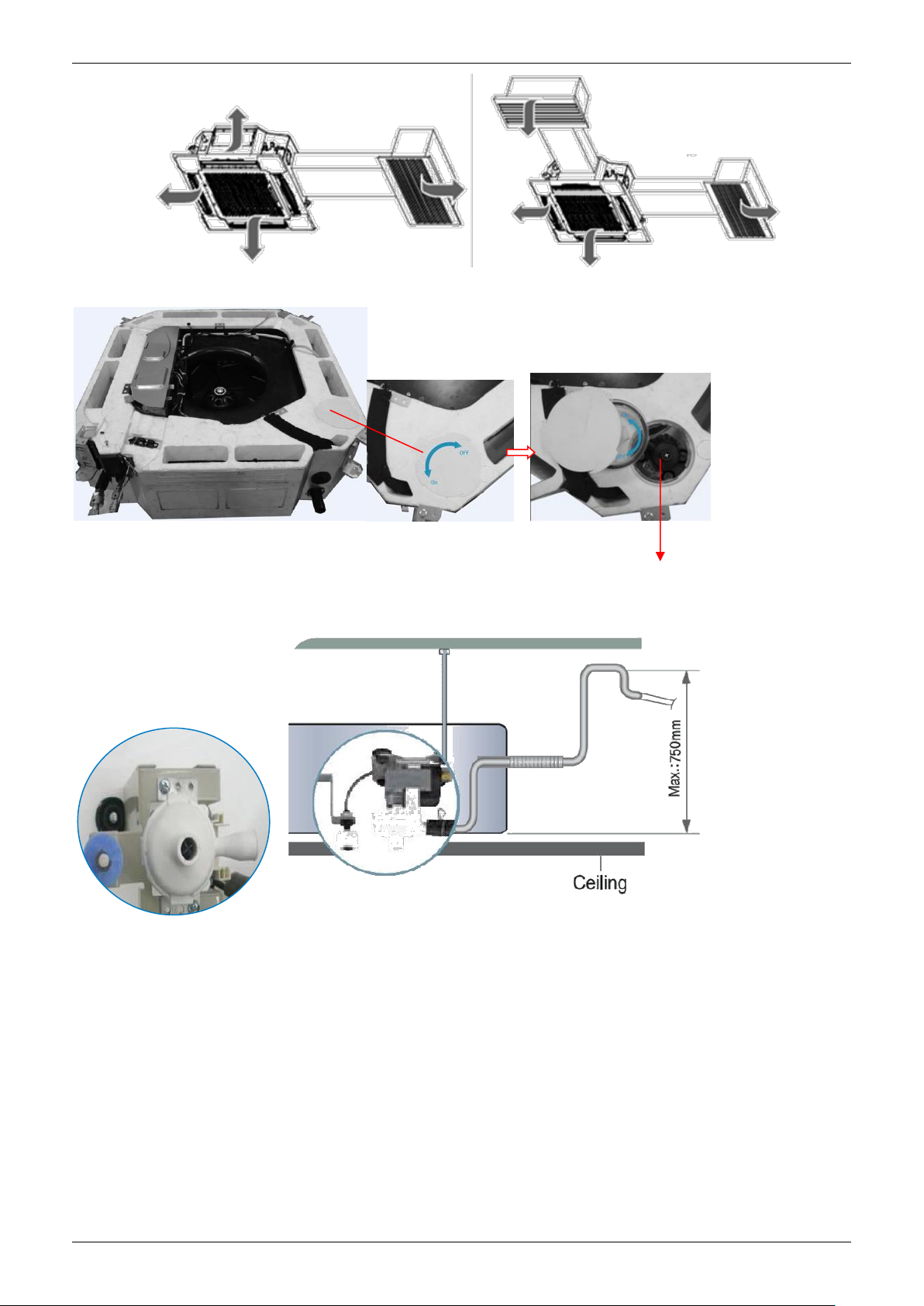
1.2 Fresh air intake function
Fresh air fulfills air quality more healthy and comfortable.
Ventilation motor is optional to increase the effect of fresh air.
1.3 Optional ionizer generator
Ionizer generator is optional to get refreshing air to your room.
Ionizer can be switched on or off by remote controller.
When pressing the Clean Air button on the remote controller, Ionizer will work and the indicator light on
display board will shine.
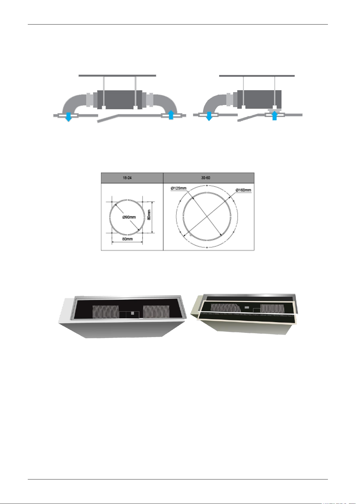
1.4 External air duct design
Reserve external air duct, more flexible for the air supply.
Indoor Units 9
Features
Draining Pump
1.5 Built-in draining pump
Due to the improvement of structure, more convenient to repair or replace the draining pump.
Built-in draining pump to make sure condensed water drain out reliably.
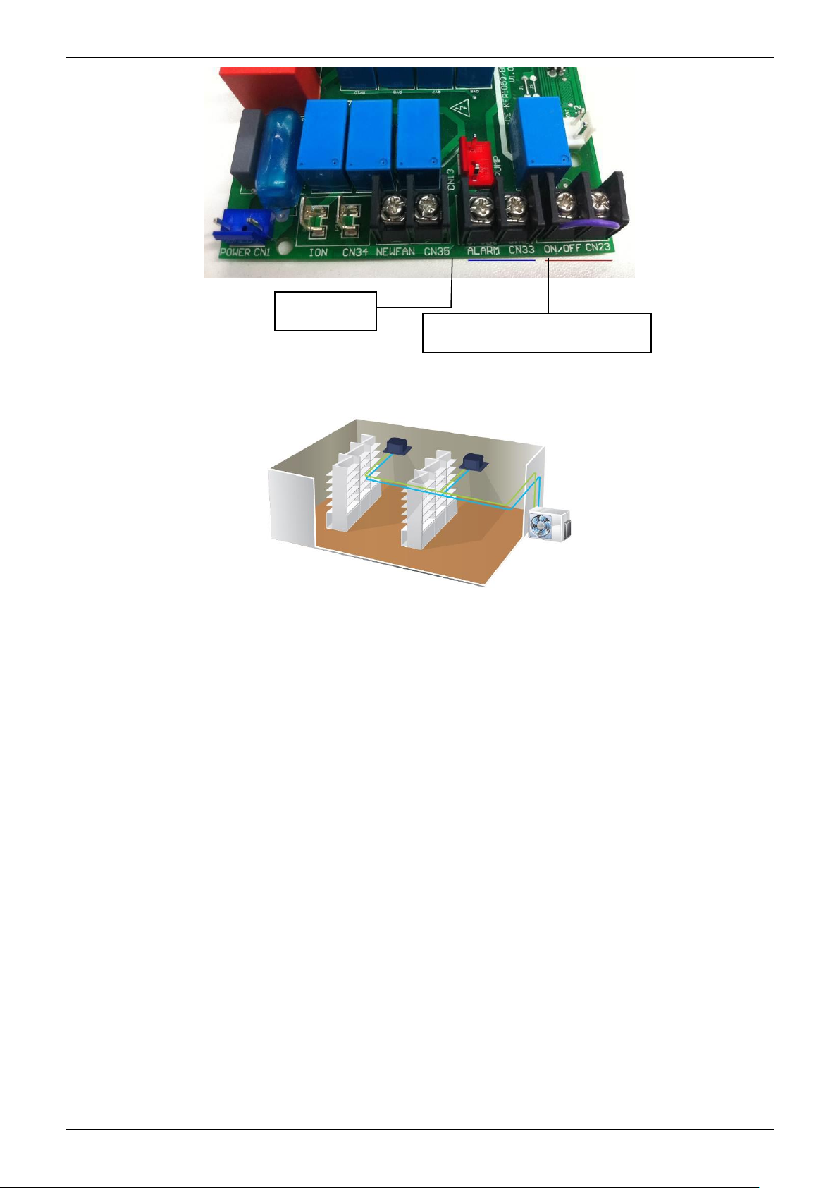
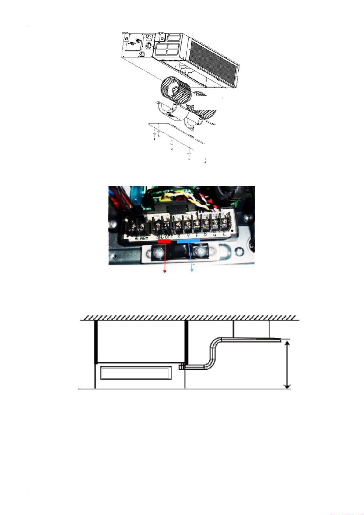
1.6 Terminals for alarm lamp and long-distance on-off controller connection are
standard
Reserve terminals for the connection of alarm lamp and long-distance on-off controller, more human
control.
Indoor Units 10
Features
Alarm lamp
Long-distance on-off controller
1.7 Twins Combination(18k-30k)
The units can be installed as Twin systems: one outdoor unit can connect with two indoor units. The
indoor units can be combined in any of the different available ratings.
Indoor Units 11
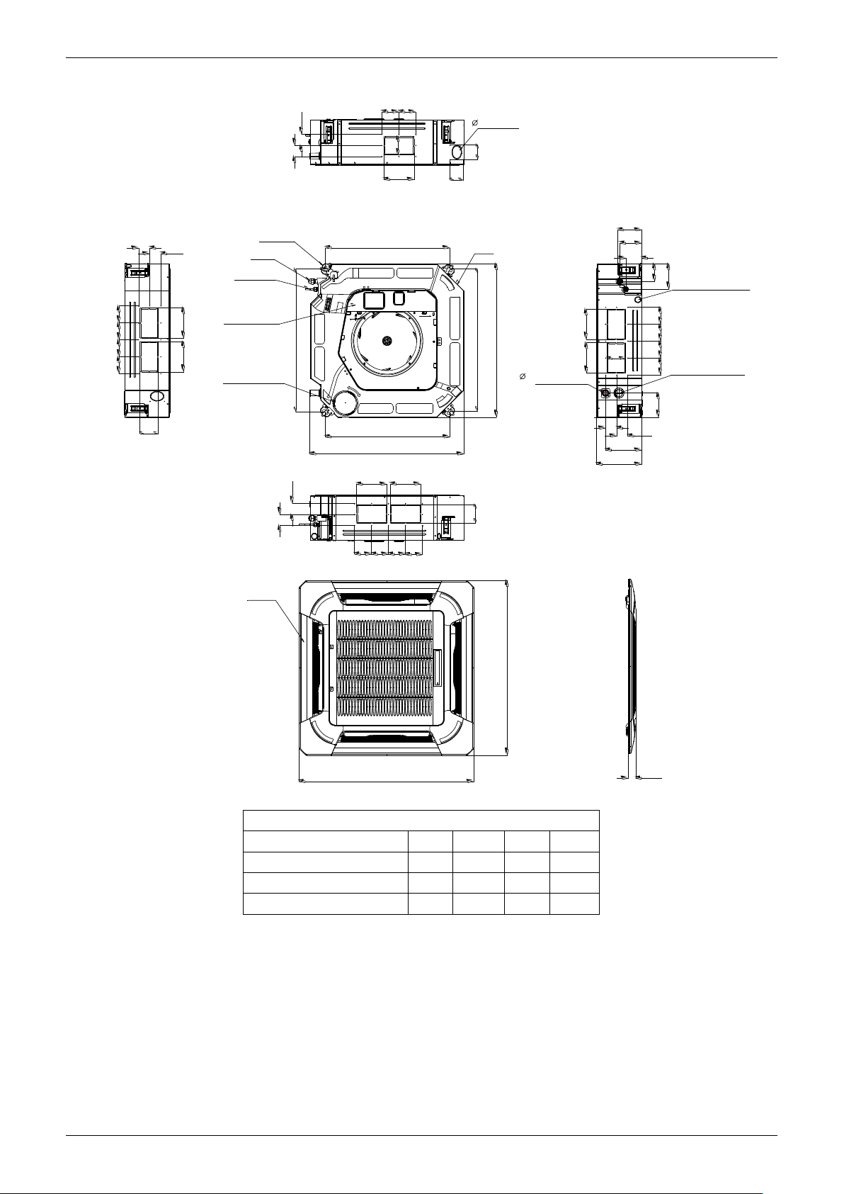
Dimensions
840
840
950
950
C
Test mouth &
Test cover
Drain h ole
32
Wiring connection port
680
780
780
680
136
126
91
196
132
A
A
B
A
A
B
A
A
B
A
B
Service hole for
draining pum p
Fresh air intak e
75
55
80
80
4-install hanger
Gas side
Liqu id side
E-parts box
135
90
Pan el
Body
92929292
D
D
92 92
D
D
D
D
92
9292
92
92 92
92
92
D
D
Unit: mm
Model(kBtu/h)
A B C
D
18
160
75
205
50
24~42
160
95
245
60
48~60
160
95
287
60
2. Dimensions
Indoor Units 12
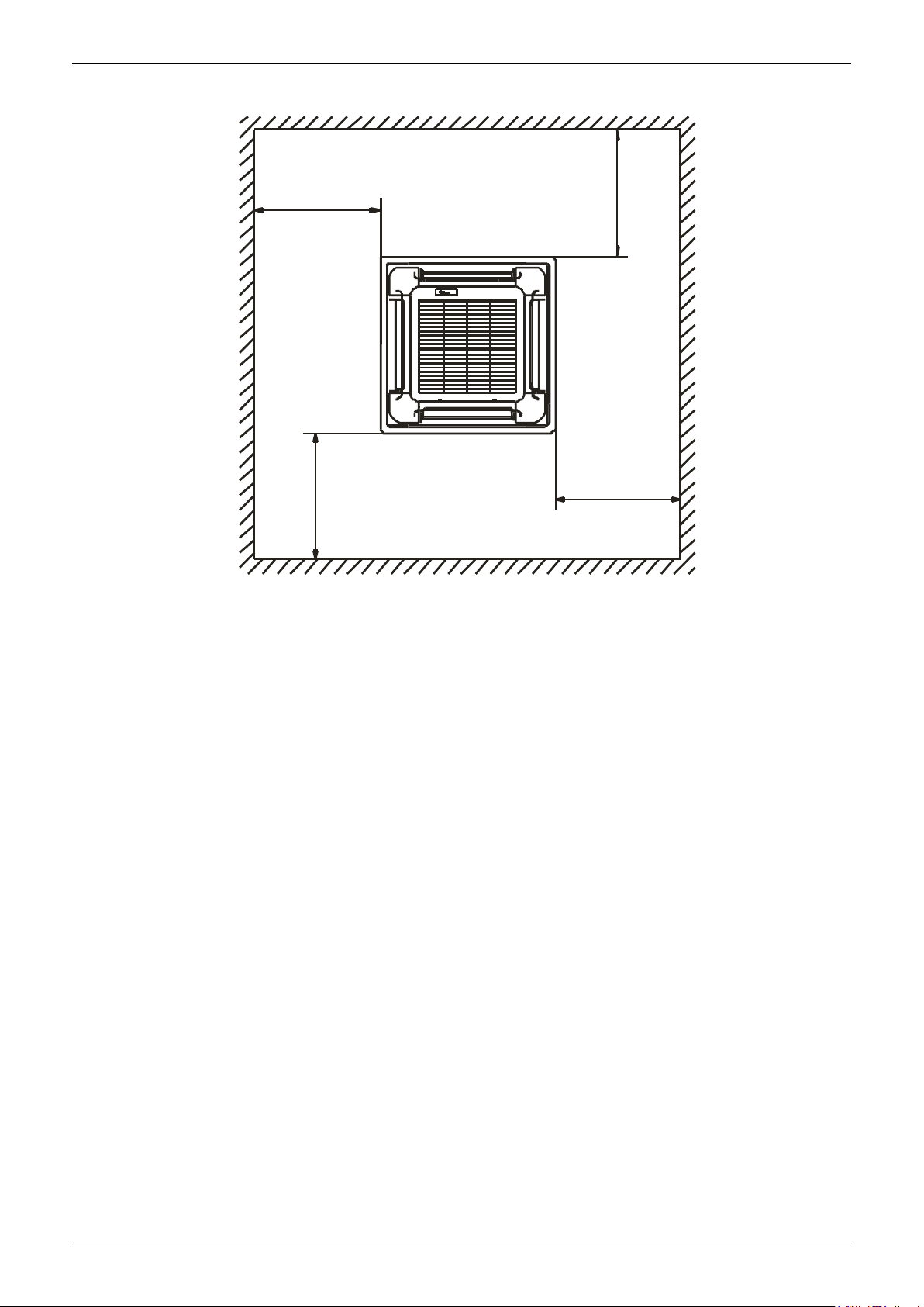
>1000m m
>1000mm
>1000mm
>1000mm
780(Hook-location)
880(Ceiling hole)
>2500mm
out let intle t outlet
ground
Chart 1
No te:
880mm
Hook
B
Panel
Chart 2
Body
Bolt M6X12
180 00-24000Btu/h(R 22) Series A 26 0mm
36000-48000Btu/h(R 22) Series A 330mm
≥
≥
No te:
180 00- 24000B tu/h (R 22) Seri es B= 240mm
3 60 00- 48000B tu /h(R22) Serie s B= 310mm
Service Space
3. Service Space
Indoor Units 13
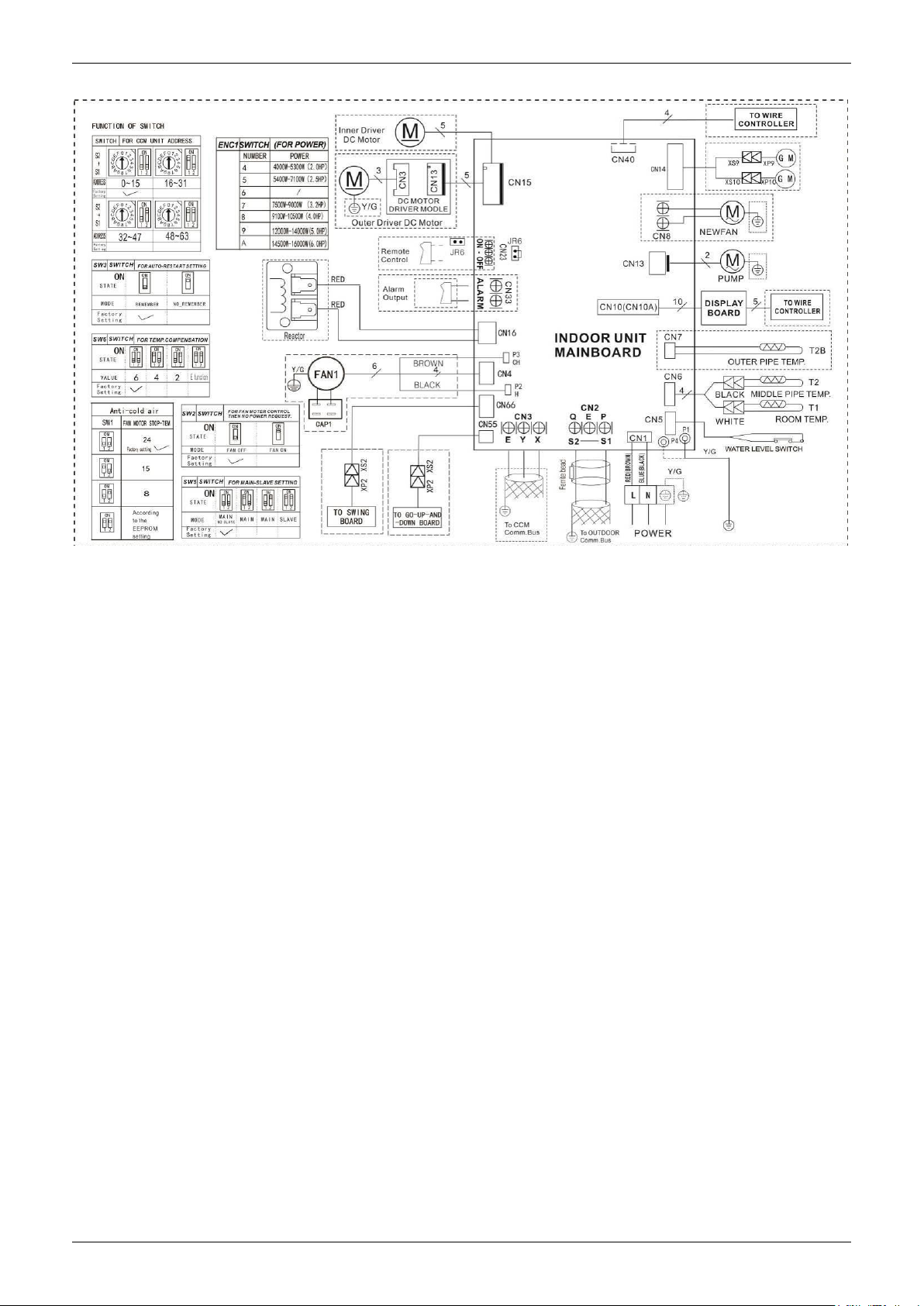
Wiring Diagrams
4. Wiring Diagrams
Indoor Units 14
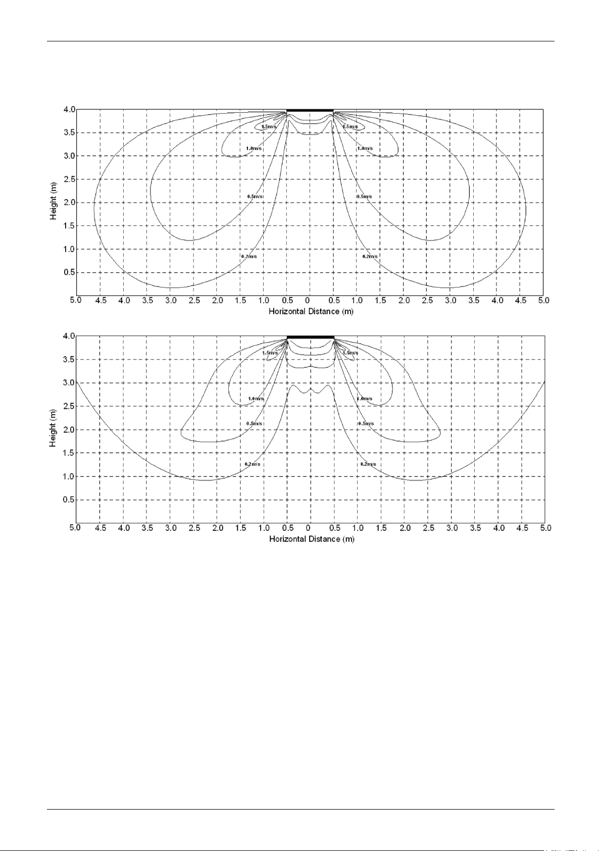
Air Velocity Distributions (Reference Data)
5. Air Velocity Distributions (Reference Data)
18-24K:
Cooling:
Heating:
Indoor Units 15
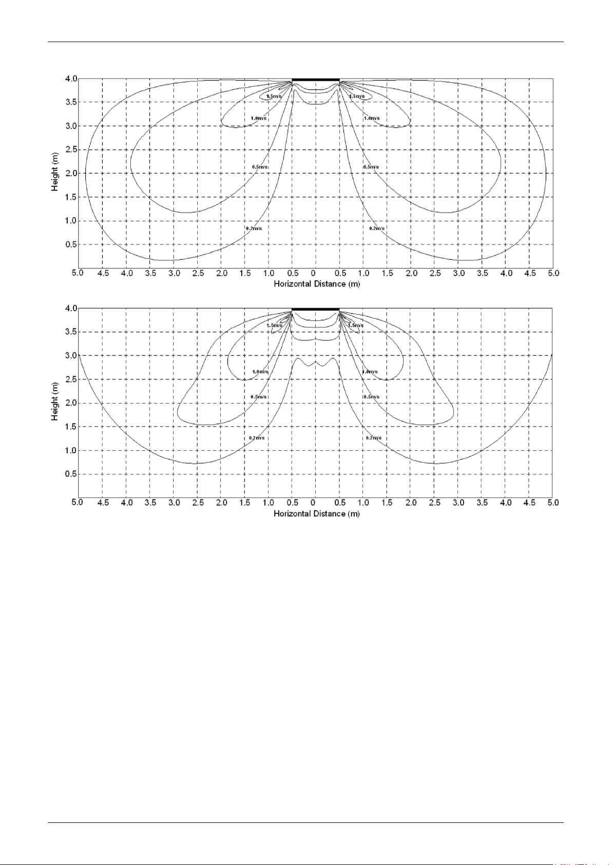
Air Velocity Distributions (Reference Data)
30-42K:
Cooling:
Heating:
Indoor Units 16
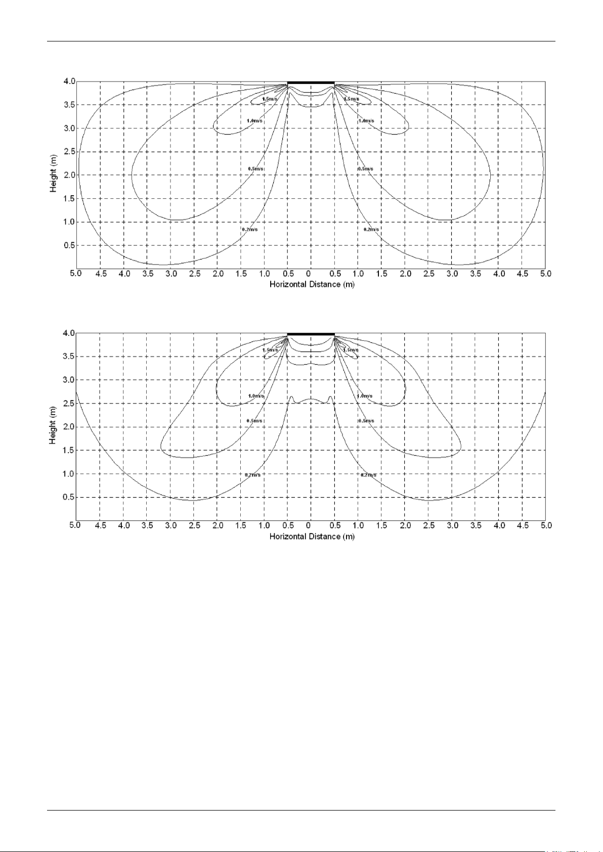
Air Velocity Distributions (Reference Data)
48-55K:
Cooling:
Heating:
Indoor Units 17

6. Electric Characteristics
Indoor Unit
Power Supply
50
220-240V
198V
254V
/
Electric Characteristics
Model
V4MCI-24UR
V4MCI-36UR
V4MCI-42
V4MCI-50UR
V4MCI-60UR
Notes:
MFA: Max. Fuse Amps. (A)
Hz Voltage Min Max MFA
50 220-240V 198V 254V /
50 220-240 198V 254V /
50 220-240V 198V 254V /
50 220-240V 198V 254V /
Indoor Units 18
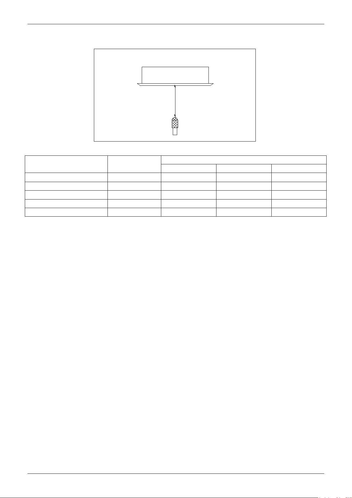
7. Sound Levels
V4MCI-24UR
V4MCI-36UR
Sound Levels
1.4m
M icr op ho ne
Model Noise Power dB(A)
V4MCI-42
V4MCI-50UR
V4MCI-60UR
Noise level dB(A)
H M L
62 46 42 39
65 56 52 48
64 52 40 47
65 55 51 48
69 52 49 46
Indoor Units 19
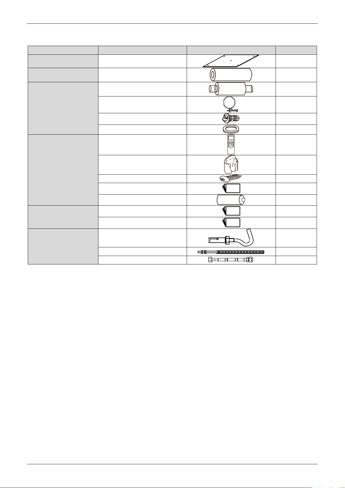
8. Accessories
Name
Shape
Quantity
Installation Fittings
Installation paper board
1
Tubing & Fittings
Soundproof / insulation sheath
1
Drainpipe Fittings
Out-let pipe sheath
1
Out-let pipe clasp
1
Drain joint
1
Seal ring
1
Remote controller & Its
Frame(The product you
have might not be
provided the following
accessories)
Remote controller & Its Frame
1
Remote controller holder
1
Mounting screw(ST2.9×10-C-H)
2
Remote controller manual
1
Alkaline dry batteries (AM4)
2
Others
Owner's manual
1
Installation manual
1
Installation accessory
(The product you have
might not be provided the
following accessories
Expansible hook
4
Installation hook
4
Orifice
1
Accessories
Indoor Units 20
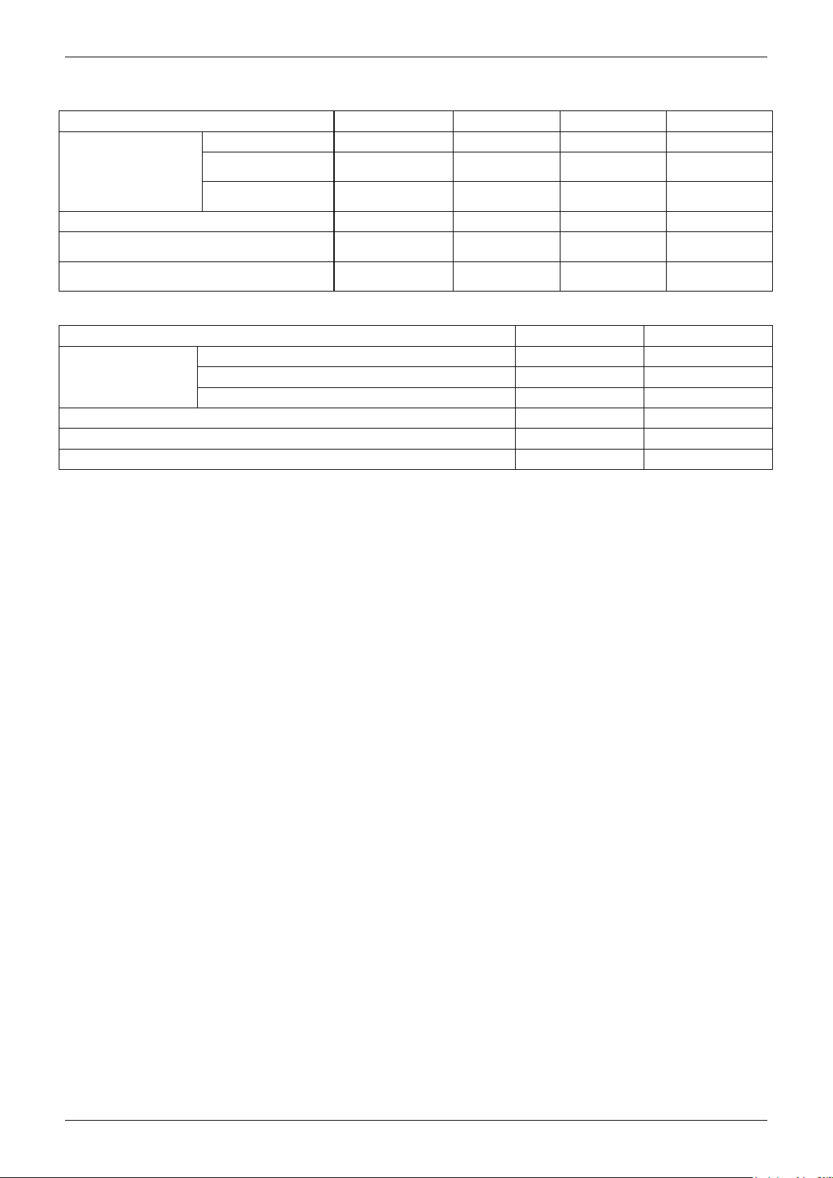
9. The Specification of Power
Model(Btu/h)
18000~24000
30000
36000
36000
POWER
Phase
1-phase
1-phase
1-phase
3-phase
Frequency and
Voltage
220-240V, 50Hz
220-240V, 50Hz
220-240V, 50Hz
380-415V, 50Hz
POWER WIRING
(mm2)
3×2.5
3×2.5
3×4.0
5×2.5
CIRCUIT BREAKER/Fuse (A)
30/20
40/30
40/30
30/20
Indoor/Outdoor Connecting Wiring
(Weak Electric Signal) (mm2)
2×0.2
2×0.2
2×0.2
2×0.2
Indoor/Outdoor Connecting Wiring
(Strong Electric Signal) (mm2)
3×1.0
3×1.0
3×1.0
3×1.0
Model(Btu/h)
42000~48000
42000~60000
POWER
Phase
1-phase
3-phase
Frequency and Voltage
220-240V, 50Hz
380-415V, 50Hz
Power Wiring (mm2)
3×4.0
5×2.5
Circuit Breaker/Fuse(A)
40/35
30/25
Indoor/Outdoor Connecting Wiring(Weak Electric Signal) (mm2)
2×0.2
2×0.2
Indoor/Outdoor Connecting Wiring(Strong Electric Signal) (mm2)
3×1.0
3×1.0
The Specification of Power
Indoor Units 21
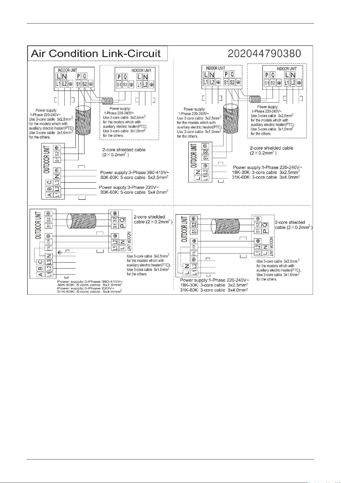
10. Field Wiring
Field Wiring
Indoor Units 22

A5 Duct Type
A5 Duct Type
1. Features ......................................................................... 24
2. Dimensions .................................................................... 27
3. Service Space ................................................................ 28
4. Wiring Diagrams ............................................................ 29
5. Static Pressure ............................................................... 31
6. Electric Characteristics ................................................. 34
7. Sound Levels ................................................................. 35
8. Accessories .................................................................... 36
9. The Specification of Power ........................................... 37
10. Field Wiring .................................................................. 38
Indoor Units 23
Features
Air intake from rear (Standard)
Air intake from bottom (Optional)
1. Features
1.1 Easy Installation: Two air inlet styles (Bottom side or Rear side)
Air inlet from rear is standard for all capacity; air inlet from bottom is optional.
The size of air inlet frame from rear and bottom is same, it’s very easy to move the cover from bottom to
rear side, or from rear to the bottom, in order to matching the installation condition.
1.2 Fresh air intake function(Optional for 18~60k)
Install one duct from the reserved fresh-air intake to outdoor.
Continually inhale the fresh air to improve the quality of the indoor air, fulfills air quality more healthy and
comfortable.
1.3 Easy maintenance
Clean the filter (Optional, standard product without filter)
It is easy to draw out the filter from the indoor unit for cleaning, even the filter is installed in rear side or
bottom side.
Replace the motor or centrifugal fan
Remove the ventilated panel firstly. Remove a half of blower housing and take out the motor with
centrifugal fan. Directly remove two bolts, and then replace the motor or centrifugal fan easily.
Indoor Units 24
Features
Motor
Blower Housing
Ventilated Panel
Remote on-off ports
Central control ports
1.4 Reserved remote on-off and central control ports
Reserved remote on-off ports and central control ports, can connect the cable of an on-off controller or a
central controller to realize remote on-off control function or group control function.
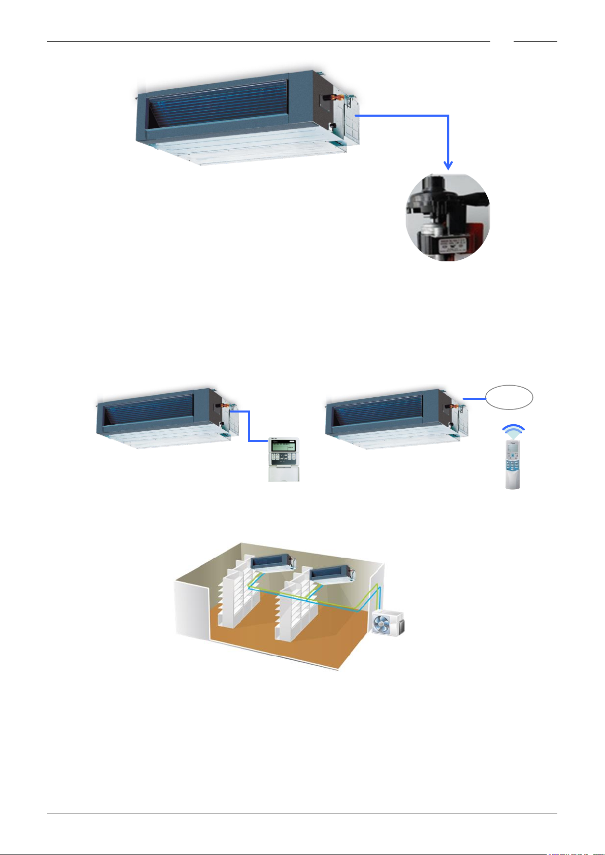
1.5 Built-in drain pump (Optional):
Built-in drain pump can lift the water to 750mm upmost. It’s convenient to install drainage piping under
most space condition.
Indoor Units 25
Features
Displa
750mm upmost
Wired Controller (Standard)
Remote Controller (Optional)
1.6 Built-in display board
The standard indoor unit can be controlled by wired controller.
There is a display board with a receiver in the E-box. Move out the display, and fix it in other place, even
in the distance of 2m. The unit will realized remoter control.
The wired controller and the display board can display the error code or protection code when the chips
detect some failure.
1.7 Twins Combination
The units can be installed as Twin systems: one outdoor unit can connect with two indoor units. The
indoor units can be combined in any of the different available ratings.
Indoor Units 26
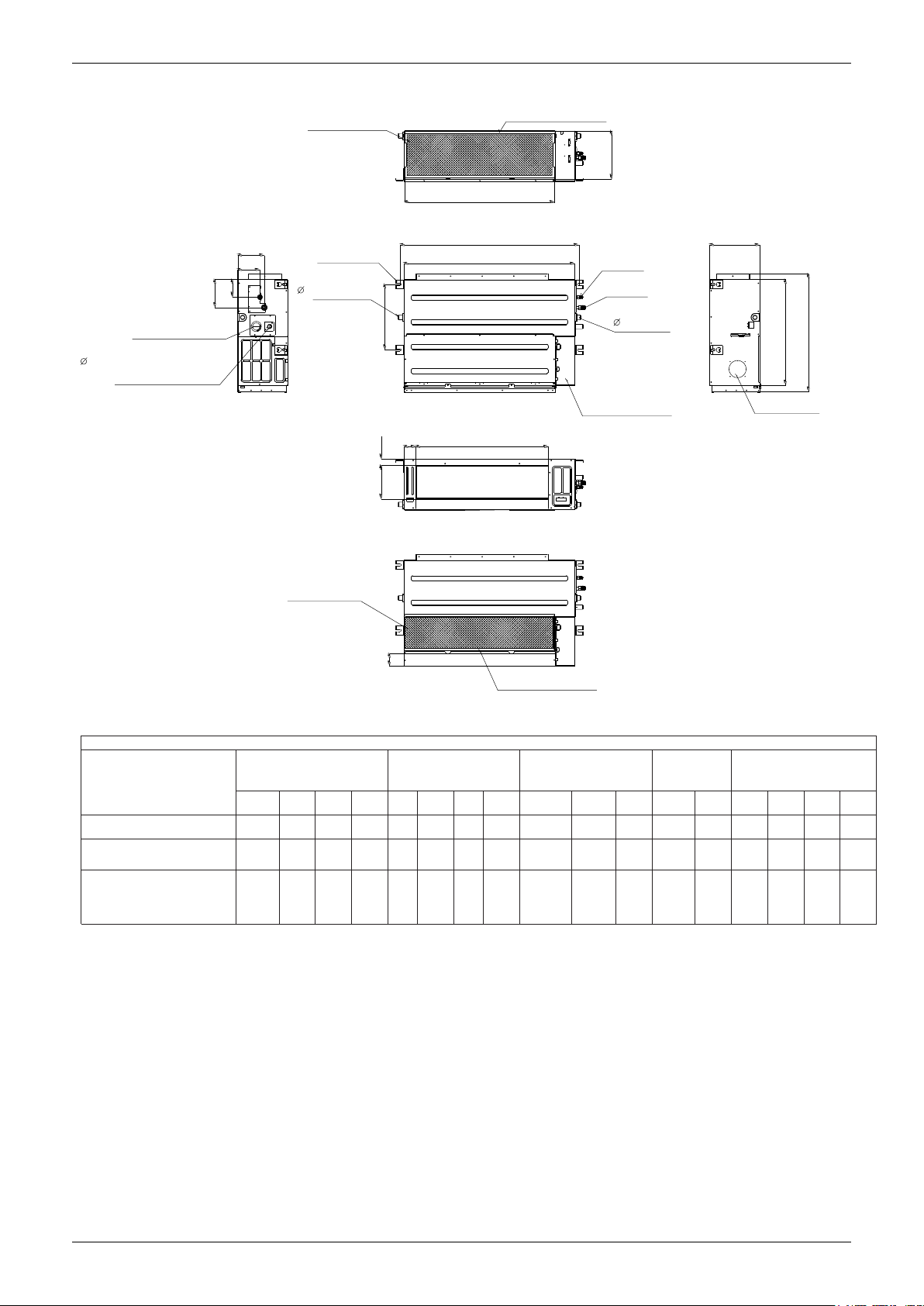
2. Dimensions
A
C
B
D
J
I
K
Air filter ( optional )
air inle t from rear side
air inle t from bottom side
FE
G
H
Electric control box
Air filter ( optional )
L
4-install hanger
Gas side
Liquid side
M
W1
W2
H1
H2
25 Drain connecting pipe
( for p u mp )
Test mouth & Test cover
Fresh air intake
25 Drain pipe
25 Drain pipe
Dimensions
Note: standard product without filter Unit: mm
V4MDI-12
V4MDI-18UR
V4MDI-24UR
V4MDI-36UR
V4MDI-42
V4MDI-50
V4MDI-60
Model
Outline dimension(mm) Air outlet opening size Air return opening size
Size of
install
Size of refrigerant pipe
hanger
A B C D E F G H I J K L M H1 H2 W1 W2
700 210 635 570 65 493 35 119 595 200 80 740 350 120 143 95 150
920 270 635 570 65 713 35 179 815 260 20 960 350 120 143 95 150
1200 300 865 800 80 968 40 204 1094 288 45 1240 500 175 198 155 210
Indoor Units 27
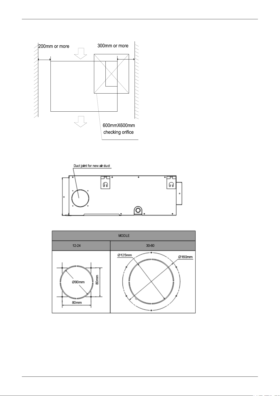
3. Service Space
Ensure enough space required for installation and maintenance.
Service Space
All the indoor units reserve the hole to joint the fresh air pipe. The hole size as following:
Indoor Units 28
 Loading...