

INVENTOR V2CI-12, V2CI-18, V2CI-24, V2CI-30, V2CI-36 Owner's Manual
...
DC
Inverter U-match Series Cassette Type Unit
V2CI-12
V2CI-18
V2CI-24
V2CI-30
V2CI-36
V2CI-45
V2CI-50
V2CI-60


1 Safety Precautions ..........................................................................................1
2 Outline of the Unit and Main Parts
...................................................................3
3 Preparative for Installation
...............................................................................4
3.1 Standard Accessory Parts
..........................................................................4
3.2 Selection of the Installation Location
..........................................................5
3.3 Connection Pipe Requirement
...................................................................7
3.4 Electrical Requirement
...............................................................................7
4 Installation of the Unit
......................................................................................9
4.1 Installation of the Indoor Unit
......................................................................9
4.2 Installation of the Outdoor Unit
.................................................................10
4.3 Installation of the Connection Pipe
...........................................................12
4.4 Vacuum and Gas Leakage Inspection
......................................................15
4.5 Installation of the Drain Hose
...................................................................17
4.6 The Panel Installation
..............................................................................20
4.7 Electrical Wiring
........................................................................................22
5 Installation of Controllers
...............................................................................27
6 Test Running
..................................................................................................27
6.1 Trial Operation and Testing
.......................................................................27
6.2 Working Temperature Range
....................................................................29
7 Troubleshooting and Maintenance
................................................................30
7.1 Troubleshooting
........................................................................................30
7.2 Routine Maintenance
...............................................................................31
Contents
DC Inverter U-match Series Cassette Type Unit
1
1 Safety Precautions
WARNING!
This mark indicates procedures which, if improperly performed, might lead to the
death or serious injury of the user.
CAUTION!
This mark indicates procedures which, if improperly performed, might possibly result
in personal harm to the user, or damage to property.
WARNING!
(1). Installation should be left to the dealer or another professional. Improper installation may cause
water leakage, electrical shock, or re.
(2). Install the air conditioner according to the instructions given in this manual. Incomplete installation
may cause water leakage, electrical shock, or re.
(3). Be sure to use the supplied or specied installation parts. Use of other parts may cause the unit to
come to lose, water leakage, electrical shock, or re.
(4). Install the air conditioner on a solid base that can support the weight of the unit. An inadequate base
or incomplete installation may cause injury in the event the unit falls off the base.
(5). Electrical work should be carried out in accordance with the installation manual and the national
electrical wiring rules or code of practice. Insufcient capacity or incomplete electrical work may
cause electrical shock or re.
(6). Be sure to use a dedicated power circuit. Never use a power supply shared by another appliance.
(7). For wiring, use a cable length enough to cover the entire distance with no connection. Do not use
an extension cord. Do not put other loads on the power supply, use a dedicated power circuit.
(Failure to do so may cause abnormal heat, electric shock or re.)
(8). Use the specied types of wires for electrical connections between the indoor and outdoor units.
Firmly clamp the interconnecting wires so their terminals receive no external stresses. Incomplete
connections or clamping may cause terminal overheating or re.
(9). After connecting interconnecting and supply wiring be sure to shape the cables so that they do not
put undue force on the electrical covers or panels. Install covers over the wires. Incomplete cover
installation may cause terminal overheating, electrical shock, or re.
(10). If any refrigerant has leaked out during the installation work, ventilate the room. (The refrigerant
produces a toxic gas if exposed to ames.)
(11). After all installation is complete, check to make sure that no refrigerant is leaking out. (The
refrigerant produces a toxic gas if exposed to ames.)
(12). When installing or relocating the system, be sure to keep the refrigerant circuit free from
substances other than the specied refrigerant (R410A), such as air. (Any presence of air or other
foreign substance in the refrigerant circuit causes an abnormal pressure rise or rupture, resulting in
injury.)
(13). During pump-down, stop the compressor before removing the refrigerant piping. If the compressor
is still running and the stop valve is open during pump-down, air will be sucked in when the
refrigerant piping is removed, causing abnormal pressure in the freezer cycle which will lead to
breakage and even injury.
DC Inverter U-match Series Cassette Type Unit
2
(14). During installation, attach the refrigerant piping securely before running the compressor. If the
compressor is not attached and the stop valve is open during pump-down, air will be sucked in
when the compressor is run, causing abnormal pressure in the freezer cycle which will lead to
breakage and even injury.
(15). Be sure to establish an earth. Do not earth the unit to a utility pipe, arrester, or telephone earth.
Incomplete earth may cause electrical shock, or re. A high surge current from lightning or other
sources may cause damage to the air conditioner.
(16). Be sure to install an earth leakage breaker. Failure to install an earth leakage breaker may result in
electric shocks, or re.
(17). This appliance is not intended for use by persons (including children) with reduced physical,
sensory or mental capabilities, or lack of experience and knowledge, unless they have been given
supervision or instruction concerning use of the appliance by a person responsible for their safety.
(18). Children should be supervised to ensure that they do not play with the appliance.
(19). If the supply cord is damaged, it must be replaced by the manufacturer, its service agent or
similarly qualied persons in order to avoid a hazard.
CAUTION!
(1). Do not install the air conditioner in a place where there is danger of exposure to inammable gas
leakage. If the gas leaks and builds up around the unit, it may catch re.
(2). Establish drain piping according to the instructions of this manual. Inadequate piping may cause
ooding.
(3). Tighten the are nut according to the specied method such as with a torque wrench. If the are
nut is tightened too hard, the are nut may crack after a long time and cause refrigerant leakage.
DC Inverter U-match Series Cassette Type Unit
3
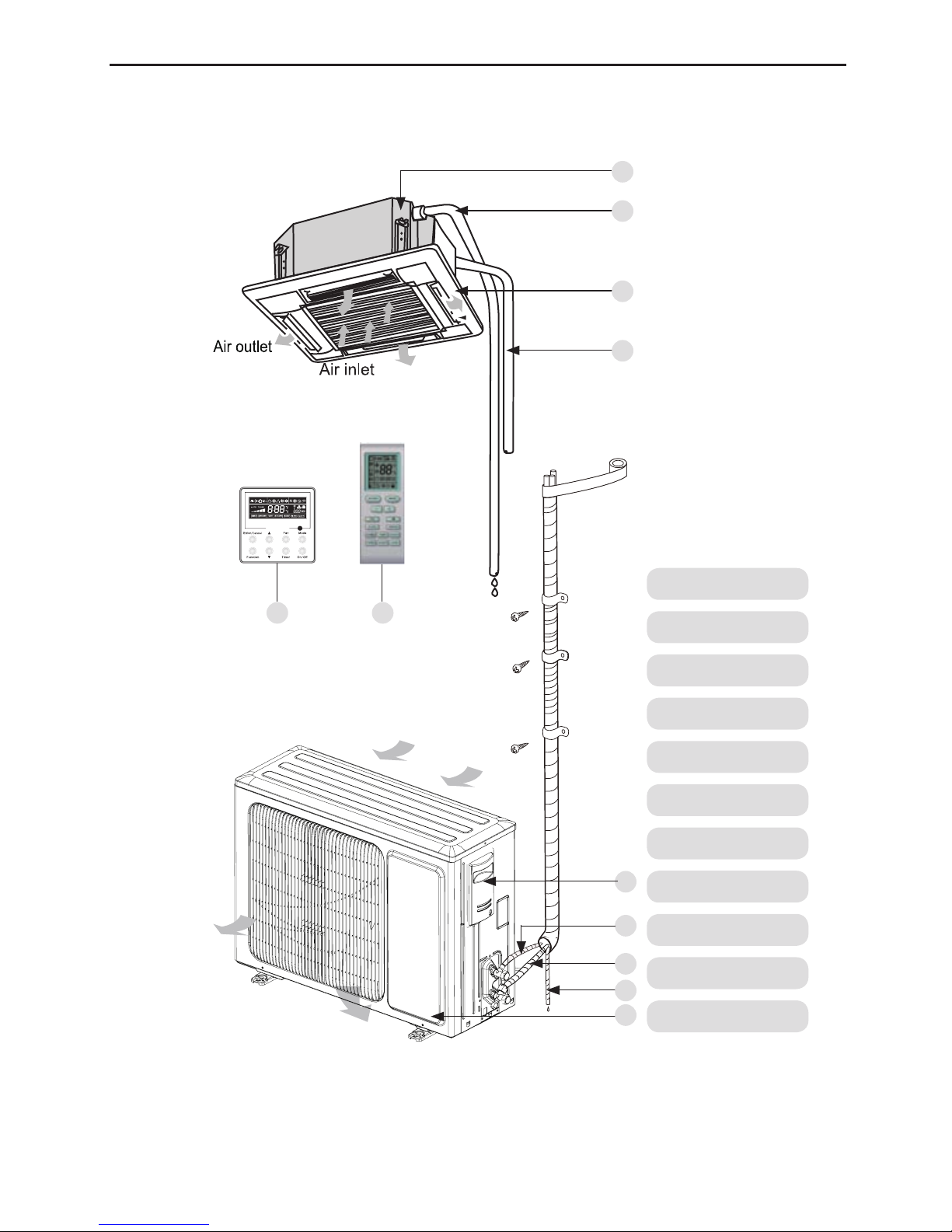
2 Outline of the Unit and Main Parts
1. Drainage device
2. Drainage pipe
3. Air ow ap
4. Connection pipe
5. Wireless Controller
6. Wired Controller
7. Big handle
8. Liquid Pipe
9. Gas pipe
10. Drainage pipe
11. Front Board
Indoor
Outdoor
2
3
4
7
5 6
1
8
9
10
11
Air inlet
Air outlet
Fig.1
DC Inverter U-match Series Cassette Type Unit
4
3 Preparative for Installation
3.1 Standard Accessory Parts
The standard accessory parts listed below are furnished and should be used as required.
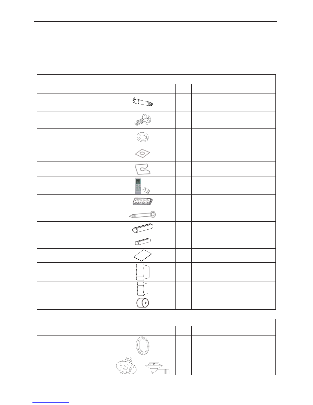
Table 1
Indoor Unit Accessories
No. Name Appearance Q'ty Usage
1 Drain Hose
1
To connect with the hard PVC drain
pipe
2 Nut with Washer
4
To x the hook on the cabinet of the
unit.
3 Washer
10
To be used together with the
hanger bolt for installing the unit.
4 installation paperboard
1 used for ceiling drilling
5 Gasket mounting board
4
Used to prevent gasket from falling
off
6
Wireless Controller
+Battery
1+2 To control the indoor unit
7 sealing plaster
1
8 Fastener 4 To fasten the sponge
9 Insulation
1 To insulate the gas pipe
10 Insulation
1 To insulate the liquid pipe
11 Sponge
4 To insulate the drain pipe
12 Nut
1 To connect gas pipe
13 Nut
1 To connect liquid pipe
14 Enswathement
2
Table 2
Outdoor Unit Accessories
No. Name Appearance Q'ty Usage
1 Drain Plug
3 To plug the unused drain hole.
2 Drainage Connecter
or
1
To connect with the hard PVC drain
pipe
DC Inverter U-match Series Cassette Type Unit
5
3.2 Selection of the Installation Location
WARNING!
The unit must be installed where strong enough to withstand the weight of the unit and xed securely,
otherwise the unit would topple or fall off.
CAUTION!
① .
Do not install where there is the danger of combustible gas leakage.
② .
Do not install the unit near heat source of heat, steam, or ammable gas.
③ .
Children under 10 years old must be supervised not to operate the unit.
Decide the installation location with the customer as follows:
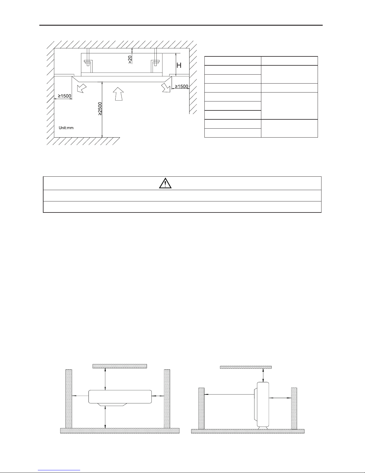
3.2.1 Indoor Unit
Select an installation site where the following conditions are fulfilled and that meets your
customer’s approval.
(1). Obstruct should be put away from the intake or outlet vent of the indoor unit so that the
airow can be blown through all the room.
(2). Make sure that the installation meets the requirement of the schematic diagram of
installation spaces.
(3). Select the place where can stand 4 times of the weight of the indoor unit and would not
increase the operating noise and vibration.
(4). The horizontality of the installation place should be guaranteed.
(5). Select the place where is easy to drain out the condensate water, and connect with outdoor
unit.
(6). Make sure that there are enough space for care and maintenance, and the height fall
between the indoor unit and ground is above 1800mm.
(7). When installing the suspension bolt, check if the installation place can stand 4 times of the
weight of the unit. If not, reinforce it before installation.
Note: There will be large amount of greasy dirt accumulated on the fan, heat exchanger and water
pump located in the dinning room and kitchen, which would reduce the capacity of the heater
exchanger, lead to leakage and abnormal operation of the water pump.
DC Inverter U-match Series Cassette Type Unit
6
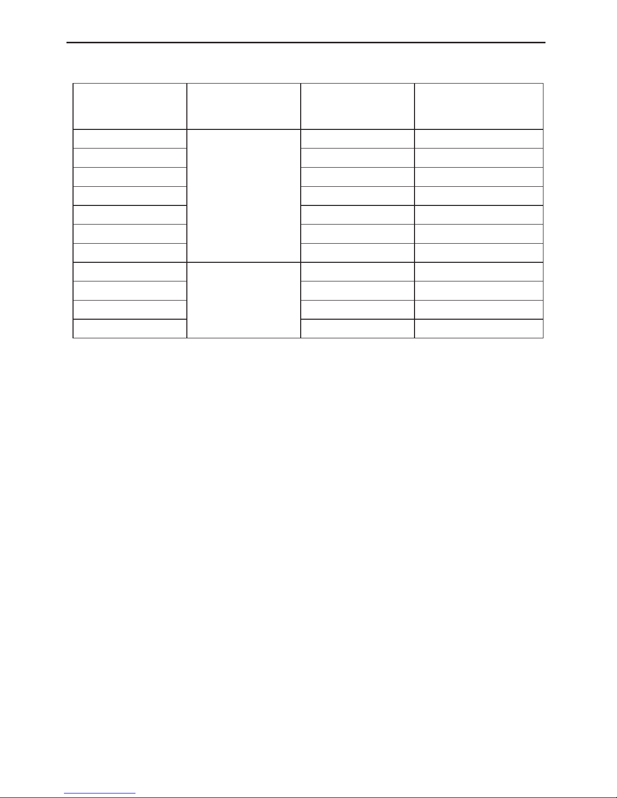
Models H(mm)
V2CI-12
255
V2CI-18
V2CI-20 260
V2CI-30
340V2CI-36
V2CI-45
V2CI-50
320
V2CI-60
Table 3
Fig.2
3.2.2 Outdoor Unit
WARNING!
① .
Install the unit where it will not be tilted by more than 5°.
② .
During installation, if the outdoor unit has to be exposed to strong wind, it must be xed securely.
If possible, do not install the unit where it will be exposed to direct sunlight. (If necessary, install
a blind that does not interfere with the air ow.)
(1). Install the outdoor unit in a place where it will be free from being dirty or getting wet by rain
as much as possible.
(2). Install the outdoor unit where it is convenient to connect with the indoor unit.
(3). Install the outdoor unit where the condensate water can be drained out freely during
heating operation.
(4). Do not place animals and plants in the path of the warm air.
(5). Take the air conditioner weight into account and select a place where noise and vibration
are small.
(6). Install the outdoor unit where is capable of withstanding the weight of the unit and
generates as less noise and vibration as possible.
(7). Provide the space shown in Fig.3, so that the air flow is not blocked. Also for efficient
operation, leave three of four directions of peripheral constructions open.
Units: mm
>500
>500 >500
>500
>2000
>2000
>1000
Fig.3
DC Inverter U-match Series Cassette Type Unit
7
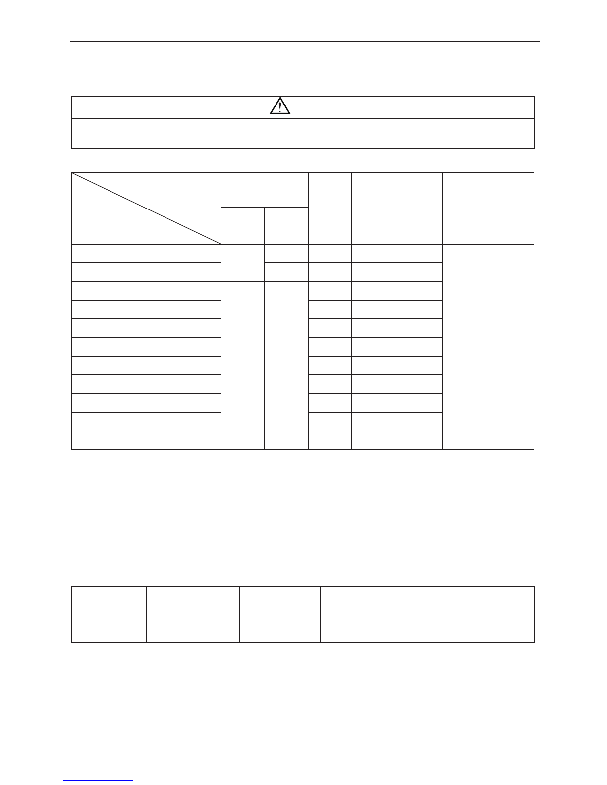
3.3 Connection Pipe Requirement
CAUTION!
The maximum length of the connection pipe is listed in the table below. Do not place the units between
which the distance exceeds the maximum length of the connection pipe.
Table 4
Item
Model
Size of Fitting
Pipe(Inch)
Max.
Pipe
Length
(m)
Max. Height
Difference between
Indoor Unit and
Outdoor Unit (m)
Drainage
pipe(Outer
Diameter × wall
thickness) (mm)
Liquid Gas
V2CI-12 U2RS-12
1/4
3/8 20 15
Φ25×1.5
V2CI-18 U2RS-18
1/2 20 15
V2CI-24 U2RS-24
3/8 5/8
30 15
V2CI-30 U2RS-30
30 15
V2CI-36 U2RS-36
30 15
V2CI-45 U2RS-45
50 30
V2CI-50 U2RS-50
50 30
V2CI-36 U2RT-36
30 15
V2CI-45 U2RT-45
50 30
V2CI-50 U2RT-50
50 30
V2CI-60 U2RT-60
3/8 3/4 50 30
The connection pipe should be insulated with proper water-proof insulating material.
The pipe wall thickness shall be 0.5-1.0mm and the pipe wall shall be able to withstand the
pressure of 6.0 MPa. The longer the connecting pipe, the lower the cooling and heating effect
performs.
3.4 Electrical Requirement
Electric Wire Size and Fuse Capacity.
Table 5
Indoor Units
Power Supply Fuse Capacity Breaker Capacity Min. Power Supply Cord
V/Ph/Hz A A mm
2
12K~60K 220-240V~ 50Hz 3.15 6 1.0
DC Inverter U-match Series Cassette Type Unit
8
Table 6
Model
Power
Supply
Capability of Air
Switch(A)
Minimum Sectional Area of
Power Cable and Earth line
(mm
2
)
U2RS-12
13 1.5
U2RS-18
16 1.5
U2RS-24
20 2.5
U2RS-30
20 2.5
U2RS-36
25 2.5
U2RS-45
25 2.5
U2RS-50
40 6.0
U2RT-36
380-415V 3N~
50Hz
20 2.5
U2RT-45
20 2.5
U2RT-50
25 2.5
U2RT-60
25 2.5
Notes:
① .
The fuse is located on the main board.
② .
Install the disconnect device with a contact gap of at least 3mm in all poles nearby the units
(Both indoor unit and outdoor unit).The appliance must be positioned so that the plug is
accessible.
③ .
The specications of the breaker and power cable listed in the table above are determined
based on the maximum power (maximum amps) of the unit.
④ .
The specications of the power cable listed in the table above are applied to the conduit-
guarded multi-wire copper cable (like, YJV copper cable, consisting of PE insulated wires and
a PVC cable jacket) used at 40°С and resistible to 90°С(see IEC 60364-5-52). If the working
condition changes, they should be modied according to the related national standard.
⑤ .
The specifications of the breaker listed in the table above are applied to the breaker with
the working temperature at 40°С. If the working condition changes, they should be modied
according to the related national standard.
⑥ .
Take 2 pieces of power cord of 0.75mm2 as the communication lines between indoor and
outdoor unit, with their longest lengths of 50m. Please select the appropriate line length as per
the actual installation conditions. The communication lines can not be twisted together. For
the unit (≤30K), it’s recommended to use 8m long communication line.
⑦ .
Take 2 pieces of power cord of 0.75mm2 as the communication lines between the wired
controller and the indoor unit, with their longest lengths of 30m. Please select the appropriate
line length as per the actual installation conditions. The communication lines can not be twisted
together. It’s recommended to use 8m long communication line.
⑧ .
The wire size of the communication line should be no less than 0.75mm2. It’s recommended to
take 0.75mm2 power cords as the communication line.
220-240V
~
50Hz
 Loading...