

INVENTOR V1RFI-30, V1RFO-30, V1RFI-50, V1RFO-50 Service Manual
COOLING HEATING
78/60/12 100/62/12
8300/7030//2500 9400/7800/1600
28500/24000/8500 32000/26500/5500
3600/2191/800 3600/2151/550
3600/2191 3600/2180
16.5/10 16.5/10
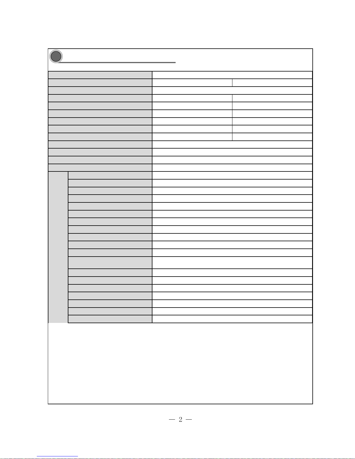
Model of Indoor Unit
Fan Motor Speed (r/min) (S/H/M/L)
Output of Fan Motor (w)
Input Power of Heater (w)
Fan Motor Capacitor (uF)
Fa n Moto r R L A( A)
Fan Type-Piece
Diameter-Length (mm)
Evaporator
Pipe Diameter (mm )
Row-Fin Gap(mm)
Coil length (l) x height (H) x coil width
(L)
Swing Motor Model
Output of Swing Motor (W)
Fus e (A)
Sound Press ure Level dB (A) (H/M/L)
Sound Power Level dB (A) (H/M/L)
Dimension (W/H/D) ( mm)
Dimension of Package (L/W/H)( mm)
Aluminum fin-copper tube
7
3-1.4
4uF
0.68
Cross flow fan – 1
108 X 954
90
V1RFI-30
540/460/420/370
Air F l o w Vol u m e (m
3
/h) (S/H /M/L)
Dehumidifying Volume (l/h)
1000/820/750/650
2
Indoor
unit
/
Model
Functio n
Rated Voltage
Frequency(Hz) (High/Standard/Low)
Total Capacity (W) (High/Standard/Low)
Total Capacity (Btu/h) (High/ Standard/Low)
Power Input (W) (High/ Standard/Low )
Energy Class
Rated Input (W) (High/ Standard)
Rated Current (A) (High/ Standard)
EER / C .O.P (W/W) 3.2 1/3.61
A/A
V1RFI-30/V1RFO-30
220-240V~
762h42h410
Stepping motor
SM060A
ǃ
Stepping motor
MP35CB
60ǃ35
682/2005/475
PCB 3.15A Transformer 0.2A
48/45/43/40
58/55/53/50
540/1790/320
Technical specifications
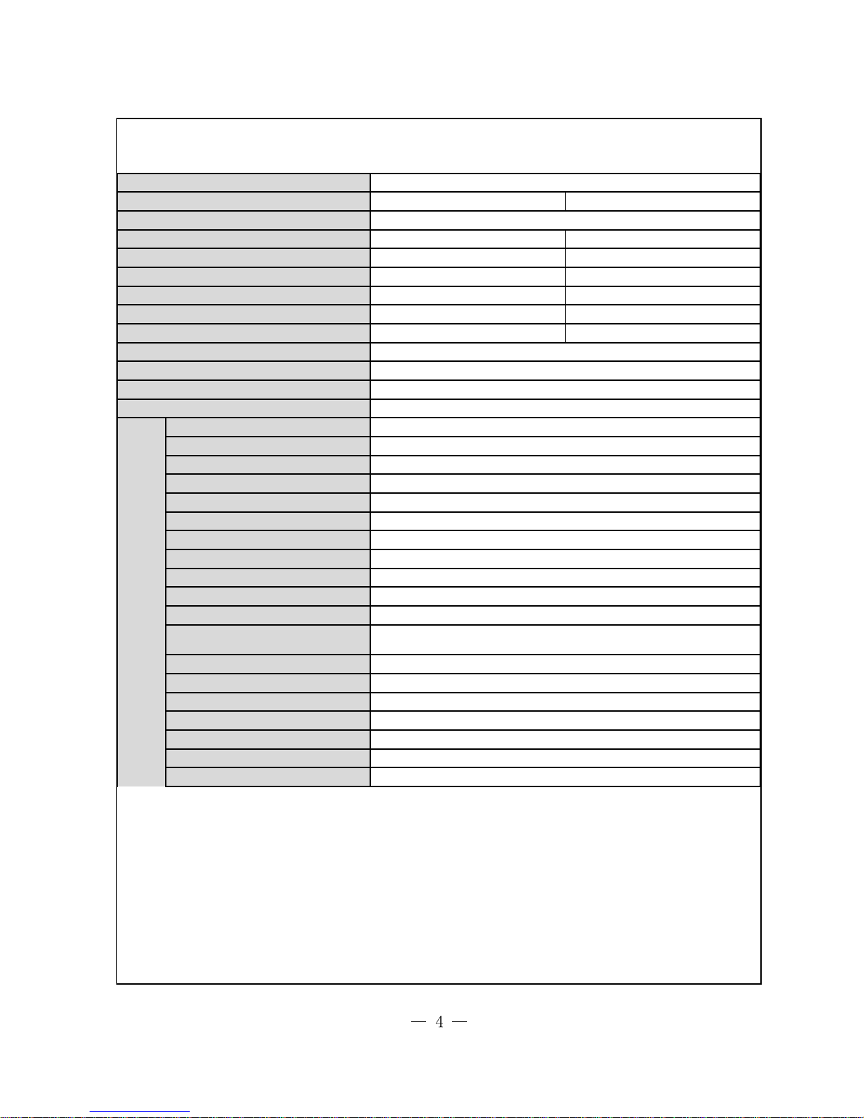
Technical specifications
2
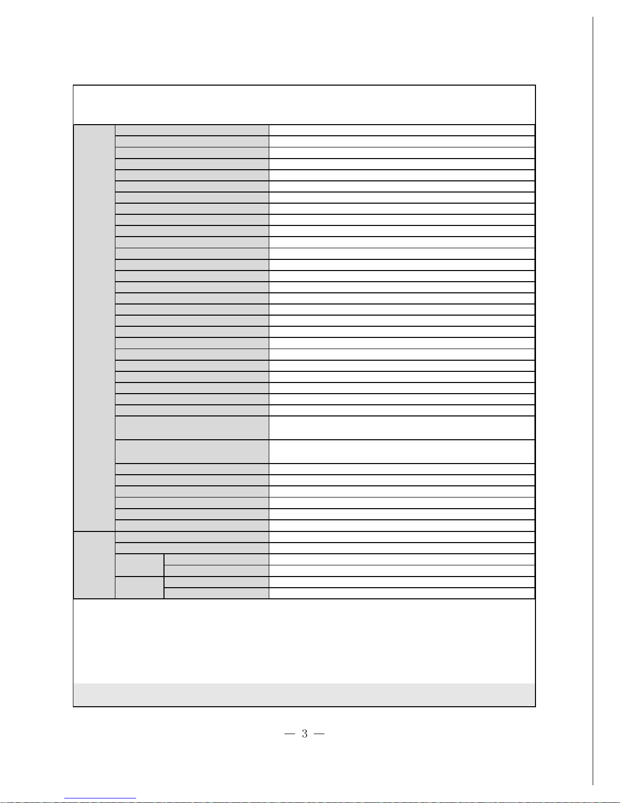
Liquid Pipe (mm)
Gas Pipe (m m )
Height (m)
Length (m)
Fan Motor Speed (rpm) (H/M/L)
Output o f Fan Moto r (W)
Condenser
Pipe Diameter (mm )
Rows-Fin Gap(mm)
Coil length (l) x height (H) x coil width
Net Wei ght /Gros s Weight (kg)
Permiss ible Excessive Operating
Pressure for the Suction Side(MPa)
Sound Press ure Level dB (A) (H/M/L)
Sound Power Level dB (A) (H/M/L)
Dimension (W/H/D) ( mm )
Dimension of Package (L/W/H)( mm)
Outer
Diameter
Refrigerant and Charge (kg)
Outdoo r
unit
Connecti
on Pipe
Gas additional charge(g/m)
Length (m)
Ma x
Distance
Model of Outdoor Unit
Compressor Manufacturer/trademark
Compressor Model
Compressor Type
L.R.A. (A)
Co m pr e ss or R L A( A)
Compressor Power Input(W)
Overload Protector
Throttling Method
Starting Method
Working Temp Range (ć)
Fa n Moto r R L A(A)
Fan Motor Capacitor (uF)
Air Flow Volume of Outdoor Unit
Fan Type-Piece
Moisture Protection
Permiss ible Excessive Operating
Pressure for the Dis charge Side(MPa)
Fan Diameter (mm)
Defrosting Method
Climate Type
Isolation
20
V1RFO-30
SANYO
C-7RZ233H1A
rotary compressor
34
8.2
1760
INTIIL-397 9
Electronic Expansion Valve
Trans d ucer s tarting
-7ćİTİ48
ć
Aluminum fin-copper tube
Φ7
2-1.4
942h748h42
780
90
0.85
7
-
Axial fan –1
Φ552
Auto defrost
T1
I
IP24
3.8
1.2
56
66
980x790x440
1065x840x485
65/71
Φ16
10
R410A/1.950
5
30g/m
Φ
6
The above data is subject to change without notice. Please refer to the nameplate of the unit.
COOLING HEATING
75/53/30 70/58/30
13500/12300/6200 15200/14000/6400
46000/42000/21000 52000/48000/22000
5500/3950/1800 5500/3900/1700
5500/3950 5500/3900
8.9 /6.8 8.9 /7.3
Model of Indoor Unit
Fan Motor Speed (r/min) (S/H/M/L)
Output of Fan Motor (w)
Input Power of Heater (w)
Fan Motor Capacitor (uF)
Fa n Moto r R L A( A)
Fan Type-Piece
Diameter-Length (mm)
Evaporator
Pipe Diameter (mm )
Row-Fin Gap(mm)
Coil length (l) x height (H) x coil width
(L)
Swing Motor Model
Output of Swing Motor (W)
Fus e (A)
Sound Press ure Level dB (A) (H/M/L)
Sound Power Level dB (A) (H/M/L)
Dimension (W/H/D) ( mm)
Dimension of Package (L/W/H)( mm)
Aluminum fin-copper tube
7
3-1.4
6uF
0.68
Cross flow fan – 1
369X180
150
V1RFI-50
550/490/440/390
Air F l o w Vol u m e (m
3
/h) (S/H /M/L)
Dehumidifying Volume (l/h)
1750/1680/1600/1500
4
Indoor
unit
/
Model
Functio n
Rated Voltage
Frequency(Hz) (High/Standard/Low)
Total Capacity (W) (High/Standard/Low)
Total Capacity (Btu/h) (High/ Standard/Low)
Power Input (W) (High/ Standard/Low )
Energy Class
Rated Input (W) (High/ Standard)
Rated Current (A) (High/ Standard)
EER / C.O.P (W/W) 3.21/3.61
A/A
V1RFI-50/V1RFO-50
380-415V~
520X25.4X876
Stepping motor
SM060A
ǃ
Stepping motor
MP35CB
60ǃ35
735/2105/545
PCB 3.15A Transformer 0.2A
50/47/44/42
53/50/47/45
580/1865/400

Liquid Pipe (mm)
Gas Pipe (m m )
Height (m)
Length (m)
Fan Motor Speed (rpm) (H/M/L)
Output o f Fan Moto r (W)
Condenser
Pipe Diameter (mm )
Rows-Fin Gap(mm)
Coil length (l) x height (H) x coil width
Net Wei ght /Gros s Weight (kg)
Permiss ible Excessive Operating
Pressure for the Suction Side(MPa)
Sound Press ure Level dB (A) (H/M/L)
Sound Power Level dB (A) (H/M/L)
Dimension (W/H/D) ( mm )
Dimension of Package (L/W/H)( mm)
Outer
Diameter
Refrigerant and Charge (kg)
Outdoo r
unit
Connecti
on Pipe
Gas additional charge(g/m)
Length (m)
Ma x
Distance
Model of Outdoor Unit
Compressor Manufacturer/trademark
Compressor Model
Compressor Type
L.R.A. (A)
Co m pr e ss or R L A( A)
Compressor Power Input(W)
Overload Protector
Throttling Method
Starting Method
Working Temp Range (ć)
Fa n Moto r R L A(A)
Fan Motor Capacitor (uF)
Air Flow Volume of Outdoor Unit
Fan Type-Piece
Moisture Protection
Permiss ible Excessive Operating
Pressure for the Dis charge Side(MPa)
Fan Diameter (mm)
Defrosting Method
Climate Type
Isolation
20
V1RFO-50
SANYO
C-9RVN273H0R
rotary compressor
37.5
7.69
4380
/
Capillary
Trans d ucer s tarting
-7ćİTİ48
ć
Aluminum fin-copper tube
Φ9.52
2-1.4
750X44X1218
840
68
0.309
6
uF
/
Axial fan –2
φ472X165
Auto defrost
T1
I
IP24
3.8
1.2
58
61
950/1250/412
1110/1280/450
112/123
Φ19
10
R410A/4.0Kg
5
30g/m
Φ12
The above data is subject to change without notice. Please refer to the nameplate of the unit.
亢
䗳
ࡳ
㛑
ᓣ
ᓔ
݇
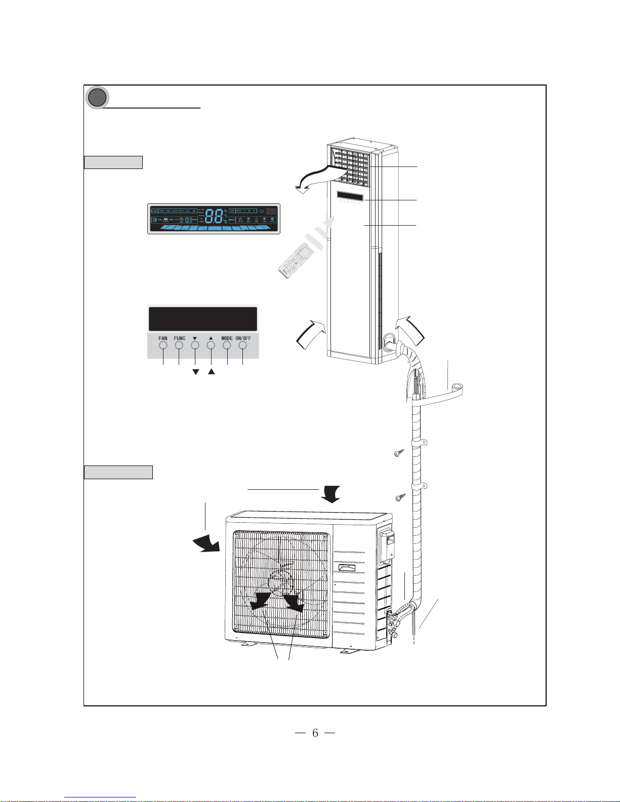
Part name
Part name3
Remote control window
Front panel
Indoor unit
Outdoor unit
Air outlet
FAN
Air in
Air out
Drainage hose
Air in
Air out
Wrapping Tape
ON/OFF
Connecting Pipe
Display Screen
FUN-
TION
MODE
Display screen
and button
Note: This photo is about the models of 24K, the appearance of model of 48K are a little different from this picture.
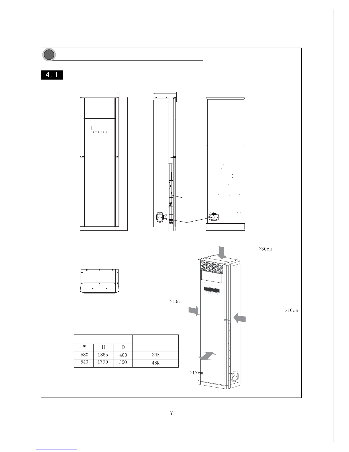
Outline and installation dimensions of indoor unit
4
Outline and installation dimension
Outline and installation dimension
WD
H
Dimension
Applicable models
Unit:mm
Air in grill
Outlet pipe opening
Rear view
Top view
Distance to ceiling
Distance to wall
To barrier
Distance to wall
Note:The distance from
tubing side to the wall
shall not be less than 30cm
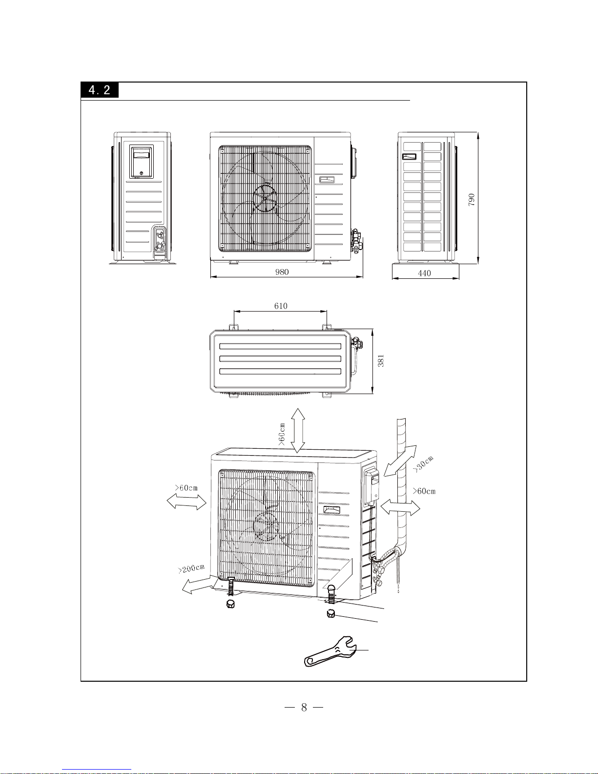
Outline and installation dimensions of outdoor unit
Unit:mm
Bolt
Nut
Wrench
V1RF0-30
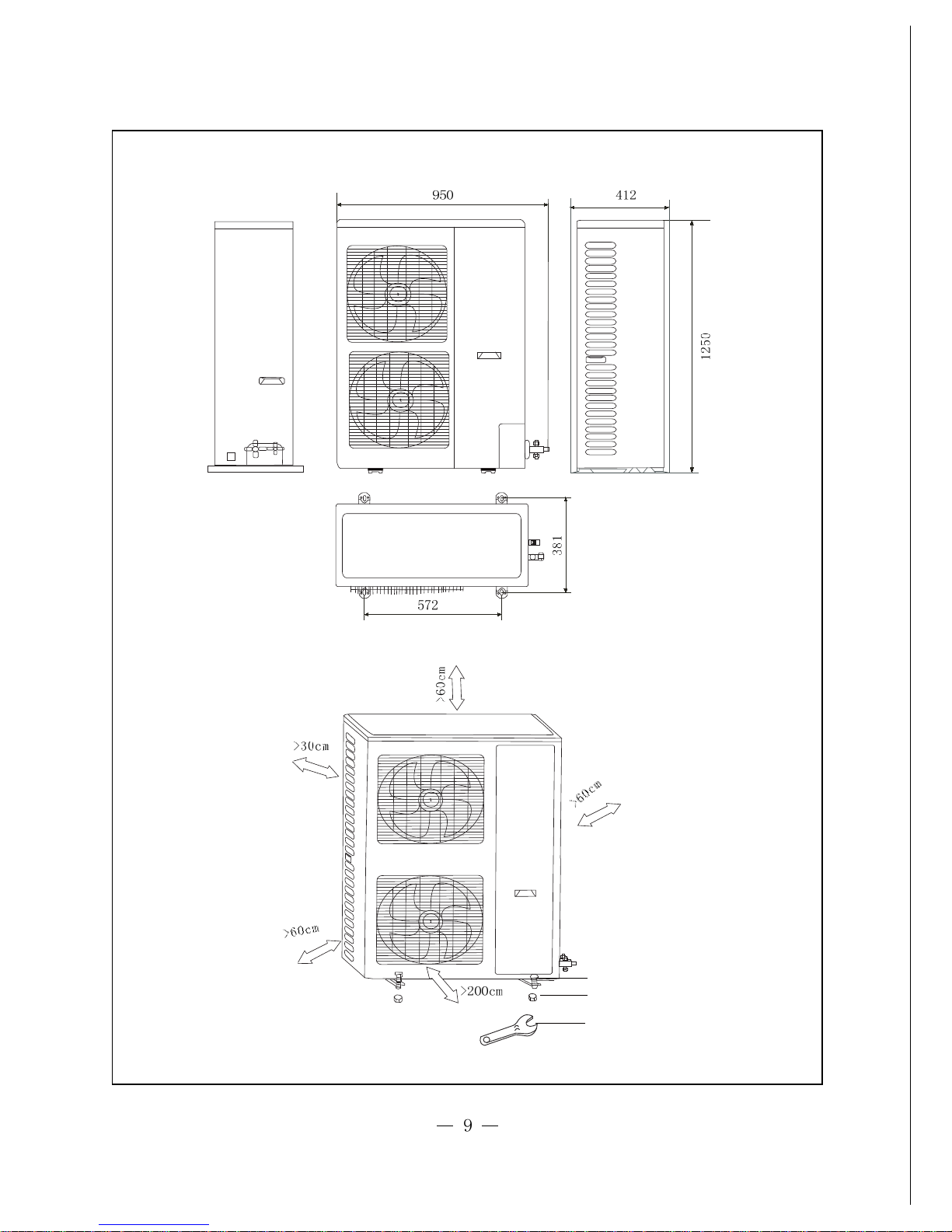
Unit:mm
Bolt
Nut
Wrench
V1RF0-50
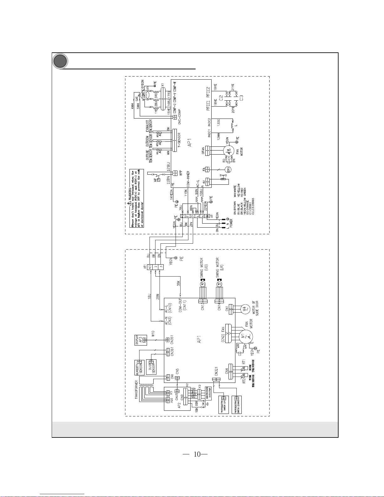
Electrical circuit diagram
Electrical circuit diagram
55
55
5
These circuit diagrams are subject to change without notice, please refer to the one supplied with the unit.
INDOOR UNIT OUTDOOR UNIT
V1RFI-30/V1RF0-30
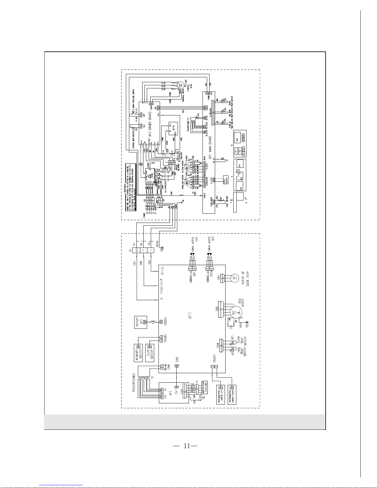
INDOOR UNIT OUTDOOR UNIT
These circuit diagrams are subject to change without notice, please refer to the one supplied with the unit.
V1RFI-50/V1RF0-50
 Loading...